design and virtual prototyping of a forklift transmission...
TRANSCRIPT

DESIGN AND VIRTUAL PROTOTYPING OF A FORKLIFT TRANSMISSION MODULE
Assoc. Prof. Dr. Todorov G.1, M. Sc. Tzv. Ivanov1, M. Sc. K. Kamberov1, bachelor eng. Sv. Stoev1
Technical University – Sofia, Bulgaria 1
Abstract: The process of design using virtual prototyping technology of a forklift transmission module is in the focus of the presented research study. Entire process is demonstrated with emphasis on the virtual prototype application in various stages as conceptual design, engineering analyses and detailed design. Higly loaded forklift transmission module is used as an example of the examined virtual technologies – through the entire study. Paticular illustration of complex structural behaviour simulation under thermal loads is presented, based on a model of brake system, where the existing empiric models are not directly applicable. Additional simulation models are also included (structural force-deflection behaviour), as well as correspondence of the virtual prototype development on each of the product development phases.
Keywords: DESIGN, VIRTUAL PROTOTYPE, TRANSMISSION, FORKLIFT, SIMULATION
1. Introduction A fundamental definition describes the engineering as a creative
application of scientific principles to design or develop structures, machines, apparatus, or manufacturing processes, or works utilizing them singly or in combination; or to construct or operate the same with full cognizance of their design; or to forecast their behavior under specific operating conditions; all as respects an intended function, economics of operation and safety to life and property. Shortly, the engineering can be viewed as a decision-making process. A proper evaluation of the alternatives requires, however, knowledge. New knowledge is created in problem solving processes. A part of the entire product development process is the engineering design. Particularly, it could be defined as a multi-step process including the research, conceptualization, feasibility assessment, establishing design requirements, preliminary design, detailed design, production planning and tool design, and finally production. [2]
All described activities deal with a large volume of information, forming a workflow through different stages. The development of computing, and the appearance of increasingly complex methods, and models to simulate physical processes and phenomena contribute to the development and enforcement of virtual prototyping. The application of virtual prototyping consists primarily in using three-dimensional computer model with a level of functional realism, similar to the physical model. Virtual prototypes application allows optimization simulations to be performed as to improve the structure of the model and thus – its major performance parameters. The aim for a model is to supply an answer to a specific question, very often – of analytical problematics. Analytical models are very important tools for clarifying and solving engineering problems – using simulations. The term simulation is used here in the broad meaning of imitating the behavior of a real system by constructing and experimenting with a computer model of the system. Tools and methods for creating and manipulating computer-based models, and for performing behavior simulations of complex systems are thus becoming increasingly important. [1, 6]
The aim of this study is to overview the product development process workflow, using contemporary methods and approaches – especially at the stages of conceptualization, feasibility assessment, establishing design requirements, preliminary design and detailed design. The complete process is based on using virtual prototype to perform different tasks on it. First stage – development of a conceptual design – involves virtual prototype to prepare the entire conception. Next step is to perform some initial calculations, as to assess the feasibility and define different design parameters. The development of preliminary design is required to be used as a basis for final design verification in the form of a detailed simulation model for analysis of product behavior under work conditions. Searching of possibility to obtain earlier implementation of the analysis reduce cost of preparation of production, shortens the time and directly provides a good cost-
effectiveness. The given example is based on a transmission module for electric forklift truck. The examined assembly is thermally loaded and the discussed approach could be applied directly. [4, 5]
Implementation of numerical techniques requires, as it was mentioned, virtual prototype, and consequence of different steps during simulation model preparation are described bellow. All these product development stages are described in detail bellow.
2. Conception and detailed design Kinematics
The developed transmission module is of type with two electric drives in parallel arangement. It should also include park brake and service brake – both of liguid cooled wet brake type. This type of brake is used because of its relatively small dimensions and the possibility to create a posi-stop brake (spring applied, hydraulics release brake, that provides the durability of an oil-immersed enclosed brake with the positive stopping action achieved by spring applied force).
Generally, the kinematics include a gearset and planetary set. The main target is to obtain high transmission ratio as to decrease the speed of used electric drives. A kinematic diagram of developed design for transmission module is shown on figure 1 bellow.
Fig. 1 Kinematics scheme of developed design
The electric motor is coupled to the input shaft through spline connection. The input shaft I transmits motion to the shaft II through a gearset postions 2 and 6. Shaft II has fixed a sun gear 7 on its end – a part from the planetary mechanism. The planetary gearset consists of sun gear 7, three planet gears 9 and crown 10, which is fixed into the housing of the gearbox. The movement is transmitted to the driven wheel 11 through the planet carrier 10.
A separate subassembly forms the liguid cooled wet brake mechanism, that combines both service brake and park brake. It consists of the spline shaft (gear) 13, fixed on shaft II, which carries the firction discs 5. These discs are coupled with steel discs 4, that are fixed to the housing. Discs 4 are movable and are pressed by piston 12. Piston 12 is operated by the brake device 3.
37
Proposed scheme is developed with the next basic characteristic parameters of the drive module:
total gearbox ratio - 23.8;
maximal transmission torque - 1620 Nm;
maximal travel speed – 16, km/h;
This stage also needs to define the required basic parameters of the brake system – both service and park brakes:
max brake torque: 1710 Nm (based on ISO 6292:1996 - "Powered industrial trucks and tractors - Brake performance and strength of the elements of the brake", type of industrial trucks, minimum braking feature is Cb = 25);
number of discs – 6;
parameters of the brake discs: outer diameter: D = 110 mm, inner diameter: d = 80 mm;
friction material having μoil = 0.1 and max allowable pressure of pmax = 1.5MPa.
Design concept
General view of the concept of the examined model is shown on figure 2 bellow. It consists of two major parts – electric motor and attached gearbox, which is the focus of the current study.
Fig. 2 Design concept – general view
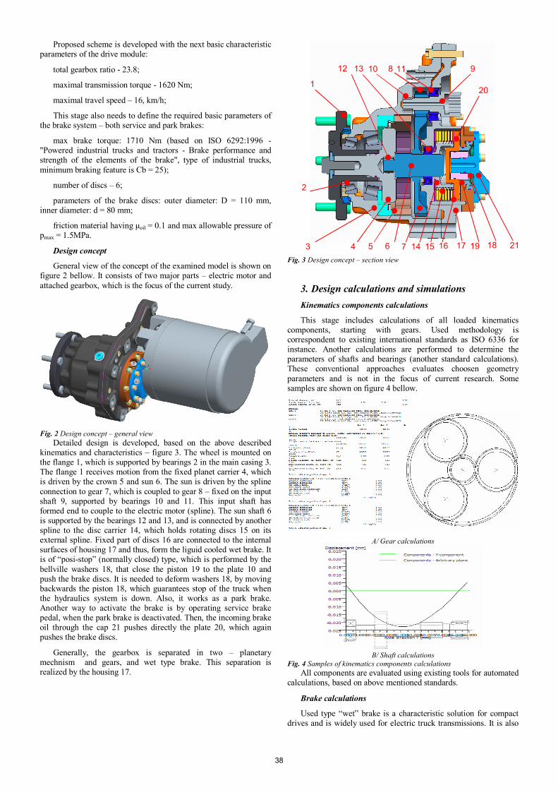
Detailed design is developed, based on the above described kinematics and characteristics – figure 3. The wheel is mounted on the flange 1, which is supported by bearings 2 in the main casing 3. The flange 1 receives motion from the fixed planet carrier 4, which is driven by the crown 5 and sun 6. The sun is driven by the spline connection to gear 7, which is coupled to gear 8 – fixed on the input shaft 9, supported by bearings 10 and 11. This input shaft has formed end to couple to the electric motor (spline). The sun shaft 6 is supported by the bearings 12 and 13, and is connected by another spline to the disc carrier 14, which holds rotating discs 15 on its external spline. Fixed part of discs 16 are connected to the internal surfaces of housing 17 and thus, form the liguid cooled wet brake. It is of “posi-stop” (normally closed) type, which is performed by the bellville washers 18, that close the piston 19 to the plate 10 and push the brake discs. It is needed to deform washers 18, by moving backwards the piston 18, which guarantees stop of the truck when the hydraulics system is down. Also, it works as a park brake. Another way to activate the brake is by operating service brake pedal, when the park brake is deactivated. Then, the incoming brake oil through the cap 21 pushes directly the plate 20, which again pushes the brake discs.
Generally, the gearbox is separated in two – planetary mechnism and gears, and wet type brake. This separation is realized by the housing 17.
Fig. 3 Design concept – section view
3. Design calculations and simulations Kinematics components calculations
This stage includes calculations of all loaded kinematics components, starting with gears. Used methodology is correspondent to existing international standards as ISO 6336 for instance. Another calculations are performed to determine the parameters of shafts and bearings (another standard calculations). These conventional approaches evaluates choosen geometry parameters and is not in the focus of current research. Some samples are shown on figure 4 bellow.
A/ Gear calculations
B/ Shaft calculations
Fig. 4 Samples of kinematics components calculations All components are evaluated using existing tools for automated
calculations, based on above mentioned standards.
Brake calculations
Used type “wet” brake is a characteristic solution for compact drives and is widely used for electric truck transmissions. It is also
1
2
3
1
4 5 6 7
8 9 10 11 12 13
14 15 16 17 18 19
20
21
38

supplied as separate component by various manufacturers as Stromag, Poclain, ZF and Dana. Development of custom solution involves calculation of its major parameters, based on existing methodlogy. Presented design is evaluated using is methodology of Dana – a global leader in the manufacture of gearboxes, torque, brakes and front axles.
Main purpose of this calculation is to determine the amount of heat being given for a typical cycle of the brake. It is determined by the amount of energy delivered to the brake in three cases of its operation – for level or uphill stops, downhill stops and retardation or downgrades:
a. Sum of energies for level or uphill stops during the duty cycle divided by the total duty cycle time:
XB
VVg
WE 1*1***5.0 21
221
b. Sum of energies for all downhill stops during the duty cycle divided by the total cycle time:
XB
HWVVg
WE 1*1****5.0 21
222
c. Sum of energies where brakes are used for retardation on downgrades during the duty cycle divided by total duty cycle time:
XB
KHWE 1*** 1
3
where: V1 and V2 are speeds at the end and start of the stop; W – machine weight; g – gravity acceleration; B – number of brakes on the truck; X – total duty cycle time; H – height of slope; K1 – fraction of grade energy absorbed by brakes.
The calculated total energy, expressed as power, is shown bellow as value:
E = 3598, kg*m/min = 588, W.
This value is used for further determination of needed oil volume and flow rate.
Brake simulations
Another important point is to determine the work temeperature of the discs, based on developed design and calculated dissipated heat in the oil. Generally, the task is quite challenging by means of simulating heat transfer brake to outer housings by oil as fluid flow thermal behaviour is a complex process. This could be overcame involving some simplifications, that will allow to preview this case as of purely structural problematics. [3]
Thermal behavior is simulated using numerical methods (Finite Element Method - FEM). Two separate analyses are required – thermal (to determine temperature distribution field) and steady-state static (to determine stress/strain behaviour under thermal loads).
The very first step of simulations is to prepare a simplified geometry model. It includes casings only, that are separated in zones – according to their contact with the oil volume. These zones are determined based on existing CFD simulations for gearboxes and are in 3 layers. The gearbox is mounted inclinated on the chassis and, thus, the zones are formed as it is shown on figure 5 bellow.
Fig. 5 Simplified geometry model
Besides this sepration, all unimportant small chamfers, rounds and holes are removed, as they will only enlarge the mesh without contributing to model accuracy.
Meshed model is prepared, based on the described simplified geometry model, and is shown on figure 6 bellow. It contains about 107 000 nodes and 67 000 20-nodes elements, which makes it sufficient for the targets of current research.
Fig. 6 Meshed model
Thermal analysis boundary conditions are shown on figure 7 bellow. They include environment temperature of 22degC, and heat flow distribution in 3x3 zones, as it is described in table 1 bellow.
Fig. 7 Boundary conditions
All external surfaces of the casings have proper convection film coefficients defined, based on natural convection laws and formulations.
The shown figure 7 also depicts the boundary conditions for the performed on next stage steady-state static analysis. It involves
III II I
A
B
C
39

temperature distribution field from the thermal analysis, the mass of components and fixation to the chassis.
Table 1: Heat flow distribution by zones. I II III
A 6% 5% B 8% 25% C
5% 12% 40%
Total 100% Used material for the casings is cast steel type GS16Mn5N
DIN 17182. Its material properties are very common to steels and are not specific.
The results from the performed thermal analysis are presented by distribution field of temperatures on figure 8. The range varies from 22degC up to 87degC. A zone with high temperature values is formed on the internal wall, that separates brake department from planetary gears.
Fig. 8 Temperature distribution field
Another results are shown on figure 9 for distribution of equivalent (von Mises) stresses on the casings – due to thermal loads applied on the structure.
Fig. 9 Equivalent (von Mises) distribution field
Stress results shows some local stress values about 93MPa. Common stress values are about 55MPa – again in the heated zone of the internal wall. Generally, the loaded part is the cover rather than the main casing – due to thermal loads of the brake during its duty cycle. These values are allowable for the used cast steel material, and is needed to be combined with acting work loads on a next step. This is not included in the current paper as the main taget is to demonstrate different stages of project development, but not the complete set of performed design procedures and separate steps.
4. Conclusions A demonstration of contemporary approach for product design
development is performed, based on virtual prototyping. The application of virtual prototype enables various actions for major poduct parameters at the stage of its design. Two main groups of approaches are demonstrated – using classical empiric calculations and using numerical simulations for physics problem description and explore of product behaviour at certain work conditions. Numerical simulations are applied to verify the design of complex shaped mechanical components. All main stages are illustrated on the basis of electric forklift transmission development example.
Follow conclusions could be marked, based on the above described performed simulations and tests:
• Design parameters assessment for forklift transmission module is performed, implementing virtual prototyping technology, especially finite elements analysis /FEA technology;
• Performed design evaluation and optimisation at early product development stage using thermal and structural simulations, gives opprtunities for adequate prediction of on-field behaviour and helps designer’s descisions;
• A competitive product have been developed with decreased expenses for its development as iterative design solutions are avoided. This reflects on decreased expenses during product development at all.
Acknowledgements This research study is performed by the support of project
DUNK-01/3 of National Science Fund, Ministery of Education, Youth and Science, Bulgaria.
REFERENCES
[1] Connel, A., (2004). The Rise and Rise of Virtual Prototyping, Time-Compression Technologies, vol.12, Issue 3.
[2] Hazelrigg,G.A., (1997). On Irrationality in Engineering Design, Journal of Mechanical Design, Vol. 119, pp.194-196, Transactions of the ASME.
[3] Lemfeld, F., Frana, K., Unger, J. (2007). Numerical Simulations of Unsteady Oil Flows in the Gear-boxes , Journal of applied science in the thermodynamics and fluid mechanics, Vol. 1, No. 1/2007, ISSN 1802-9388.
[4] Neelamkavil, F. (1987). Computer Simulation and Modelling, John Wiley & Sons.
[5] Todorov, G., Lai, Y., Kamberov, K. (2009). Development of Collaborative Approach for Virtual Prototyping based on 3D kernel and FEM analysis, Wissenschaftlichen Konferenz “Technik und Wirtschaft in der globalen Krise”, 26-27 Nov. 2009, Sofia.
[6] Tseng, M.M., Jiao, J., Su, Ch. (1998). Virtual Prototyping for Customized Product Development, Integrated Manufacturing Systems, vol. 9, no. 6, pp. 334-343.
40