design and verification of mixed-signal asics using matlab and simulink · block diagram and...
TRANSCRIPT
1© 2015 The MathWorks, Inc.
Design and Verification of Mixed-Signal
ASICs Using MATLAB and Simulink
Aniruddha Dayalu
Principal Application Engineer –
Analog/Mixed-Signal Design
2
Agenda
▪ System Level Design of Analog and Mixed-Signal Components
▪ Linking Behavioral to Circuit design and Verifying AMS designs
▪ Post-processing of simulation results
▪ Conclusion
3
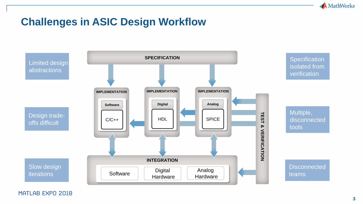
TE
ST
& V
ER
IFIC
AT
ION
IMPLEMENTATION
Analog
SPICE
IMPLEMENTATION
Digital
HDL
Specification
isolated from
verification
Disconnected
teams
Design trade-
offs difficult
Limited design
abstractions
SPECIFICATION
Slow design
iterations
Challenges in ASIC Design Workflow
IMPLEMENTATION
Software
C/C++
INTEGRATION
Digital
Hardware
Analog
HardwareSoftware
Multiple,
disconnected
tools
4
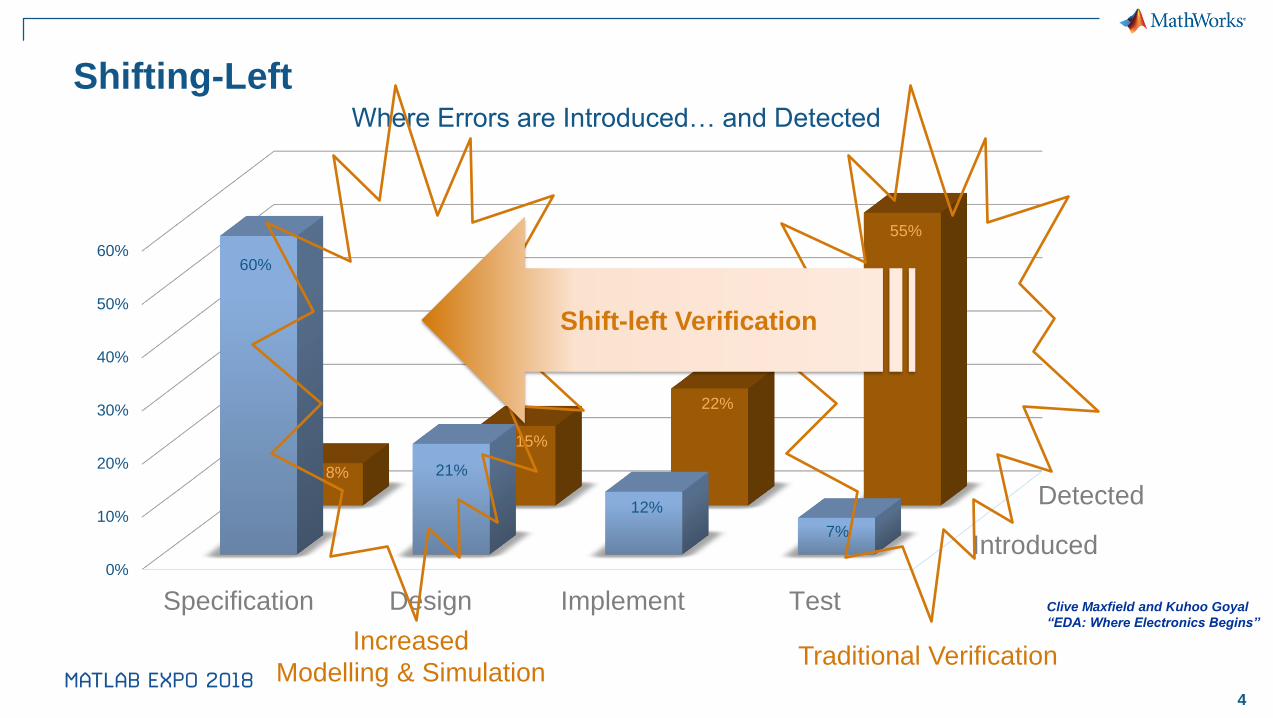
Shifting-Left
Clive Maxfield and Kuhoo Goyal
“EDA: Where Electronics Begins”
Introduced
Detected
0%
10%
20%
30%
40%
50%
60%
Specification Design Implement Test
60%
21%
12%
7%
8%
15%
22%
55%
Where Errors are Introduced… and Detected
Traditional VerificationIncreased
Modelling & Simulation
Shift-left Verification
5
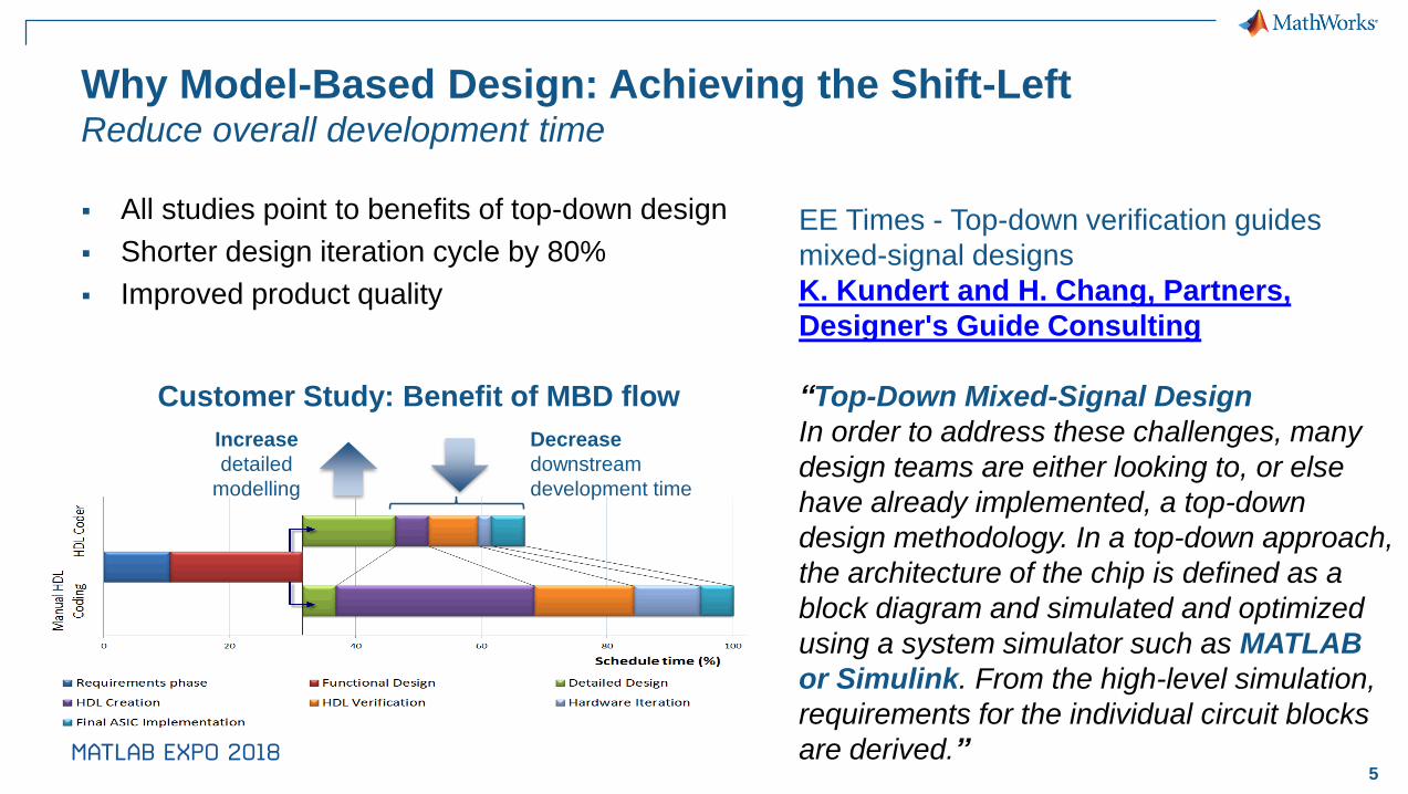
Why Model-Based Design: Achieving the Shift-LeftReduce overall development time
▪ All studies point to benefits of top-down design
▪ Shorter design iteration cycle by 80%
▪ Improved product quality
Increase
detailed
modelling
Decrease
downstream
development time
Customer Study: Benefit of MBD flow
EE Times - Top-down verification guides
mixed-signal designs
K. Kundert and H. Chang, Partners,
Designer's Guide Consulting
“Top-Down Mixed-Signal Design
In order to address these challenges, many
design teams are either looking to, or else
have already implemented, a top-down
design methodology. In a top-down approach,
the architecture of the chip is defined as a
block diagram and simulated and optimized
using a system simulator such as MATLAB
or Simulink. From the high-level simulation,
requirements for the individual circuit blocks
are derived.”

6
Customer Successes - Allegro
Allegro designs ASIC using Simulink:
▪ Interpolation engines
▪ Digital filters
▪ Signal Processing Algorithms
▪ Digital PLL’s
▪ Digital Sigma Delta DAC’s
▪ MATLAB EXPO Link

7
Analog Devices – Builds Simulink Behavioral Modelshttp://www.analog.com/en/design-center/simulation-models/mathworks-behavioral-models.html
8
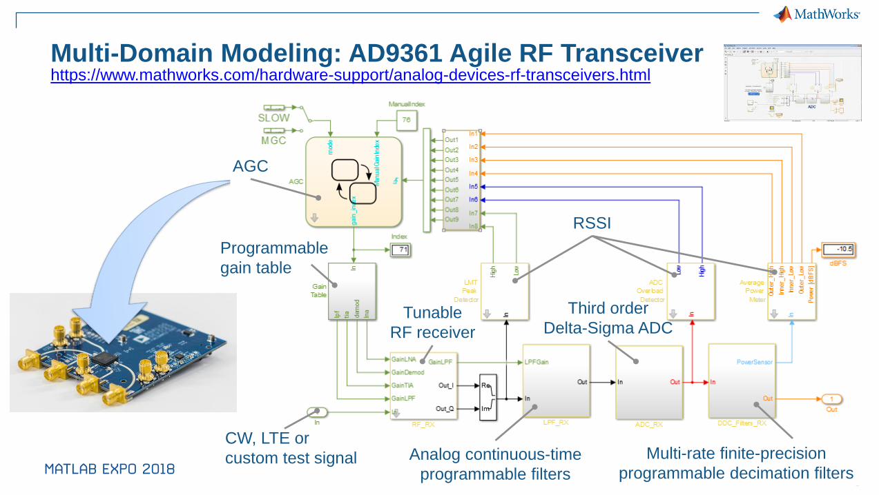
Programmable
gain table
CW, LTE or
custom test signal Multi-rate finite-precision
programmable decimation filtersAnalog continuous-time
programmable filters
Tunable
RF receiver
Multi-Domain Modeling: AD9361 Agile RF Transceiver
Third order
Delta-Sigma ADC
RSSI
AGC
https://www.mathworks.com/hardware-support/analog-devices-rf-transceivers.html
9
Agenda
✓ Current Trends in Semiconductor Design and Verification
▪ Linking Behavioral to Circuit design and Verifying AMS designs
▪ Post-processing of simulation results
▪ Conclusion
10
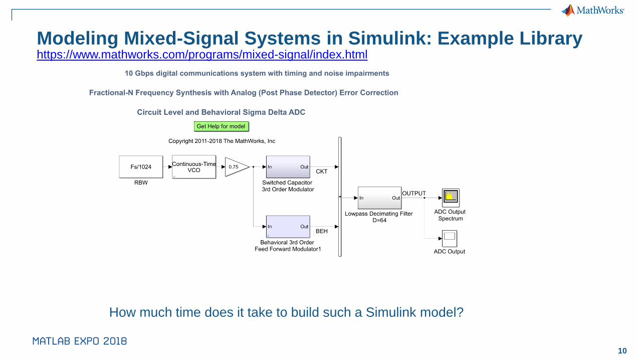
Modeling Mixed-Signal Systems in Simulink: Example Libraryhttps://www.mathworks.com/programs/mixed-signal/index.html
How much time does it take to build such a Simulink model?
11
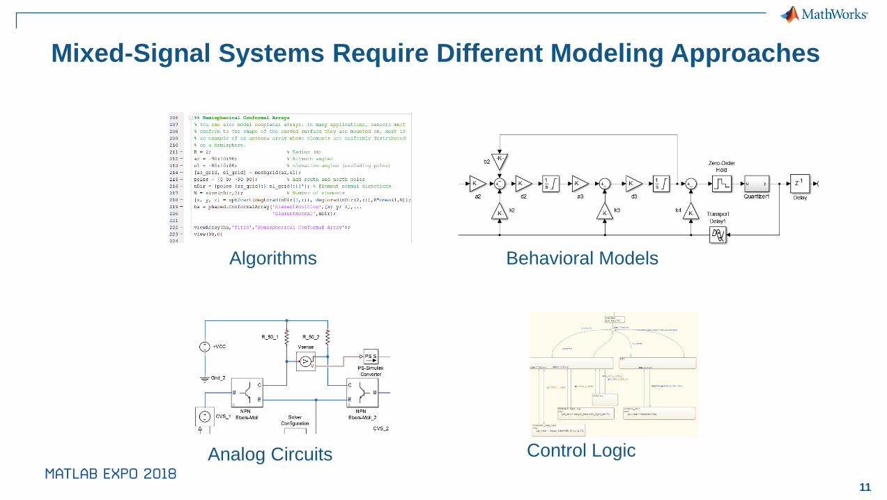
Mixed-Signal Systems Require Different Modeling Approaches
Algorithms Behavioral Models
Control LogicAnalog Circuits
12
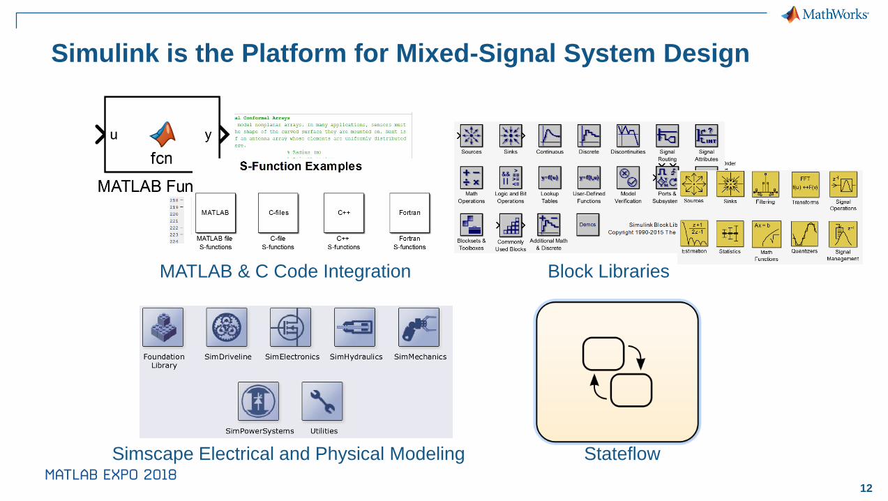
Simulink is the Platform for Mixed-Signal System Design
MATLAB & C Code Integration Block Libraries
StateflowSimscape Electrical and Physical Modeling
13
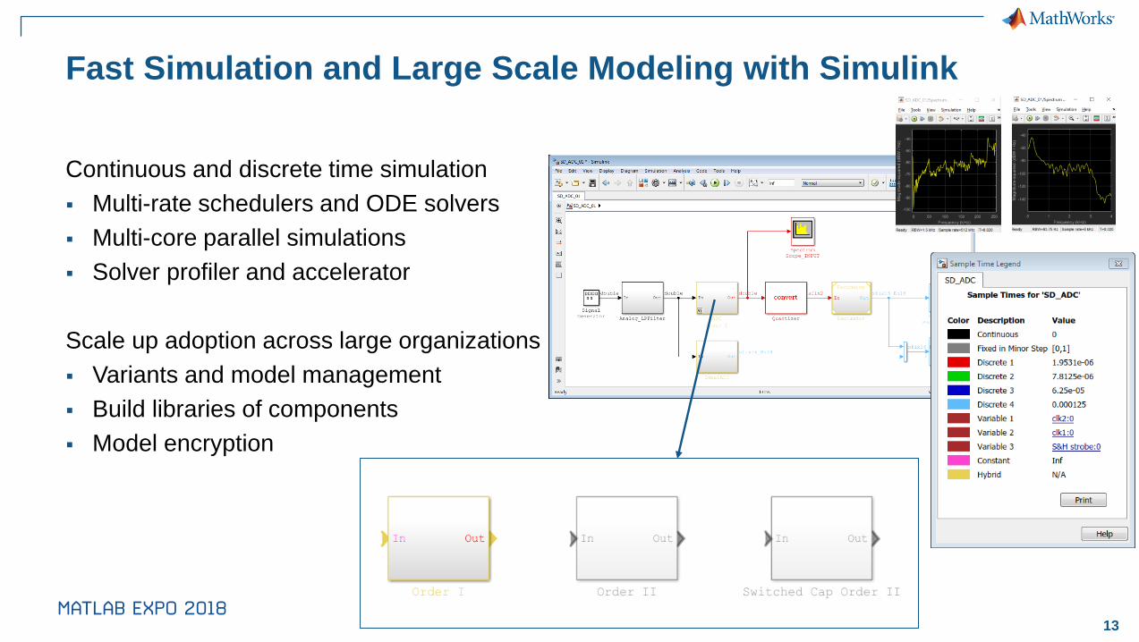
Fast Simulation and Large Scale Modeling with Simulink
Continuous and discrete time simulation
▪ Multi-rate schedulers and ODE solvers
▪ Multi-core parallel simulations
▪ Solver profiler and accelerator
Scale up adoption across large organizations
▪ Variants and model management
▪ Build libraries of components
▪ Model encryption
∑∆ Order I∑∆ Order II
Switched Capacitor ∑∆ Order II

14
Start with Designing and Implementing Digital Filters
▪ Realize model with basic Simulink blocks
▪ Export coefficients to MATLAB
▪ Create multi-rate filters
▪ Generate synthesizable HDL code

15
Agenda
✓ Current Trends in Semiconductor Design and Verification
✓ System Level Design of Analog and Mixed-Signal Components
▪ Post-processing of simulation results
▪ Conclusion
16
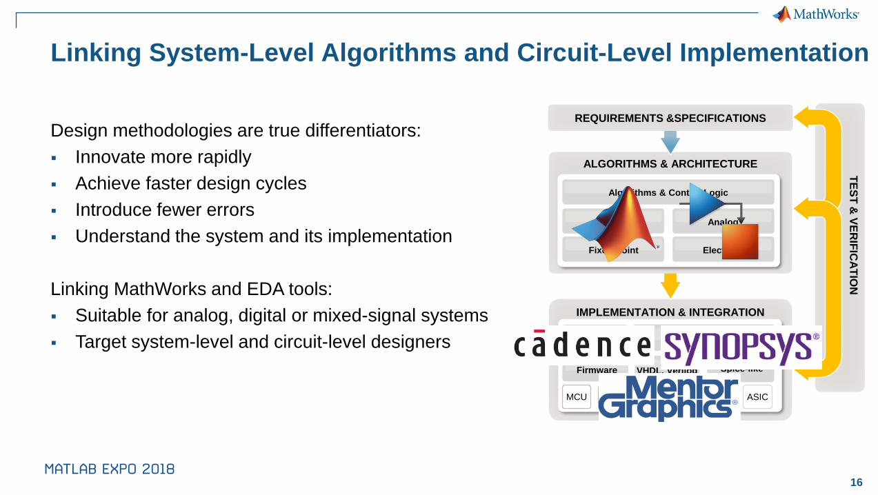
Linking System-Level Algorithms and Circuit-Level Implementation
Design methodologies are true differentiators:
▪ Innovate more rapidly
▪ Achieve faster design cycles
▪ Introduce fewer errors
▪ Understand the system and its implementation
Linking MathWorks and EDA tools:
▪ Suitable for analog, digital or mixed-signal systems
▪ Target system-level and circuit-level designers
IMPLEMENTATION & INTEGRATION
ALGORITHMS & ARCHITECTURE
TE
ST
& V
ER
IFIC
AT
ION
REQUIREMENTS &SPECIFICATIONS
FPGA ASIC PCB ASIC
Spice-like
HardwareSoftware
VHDL, Verilog
Electrical
Algorithms & Control Logic
AnalogDigital
Fixed-Point
MCU DSP
Firmware
17
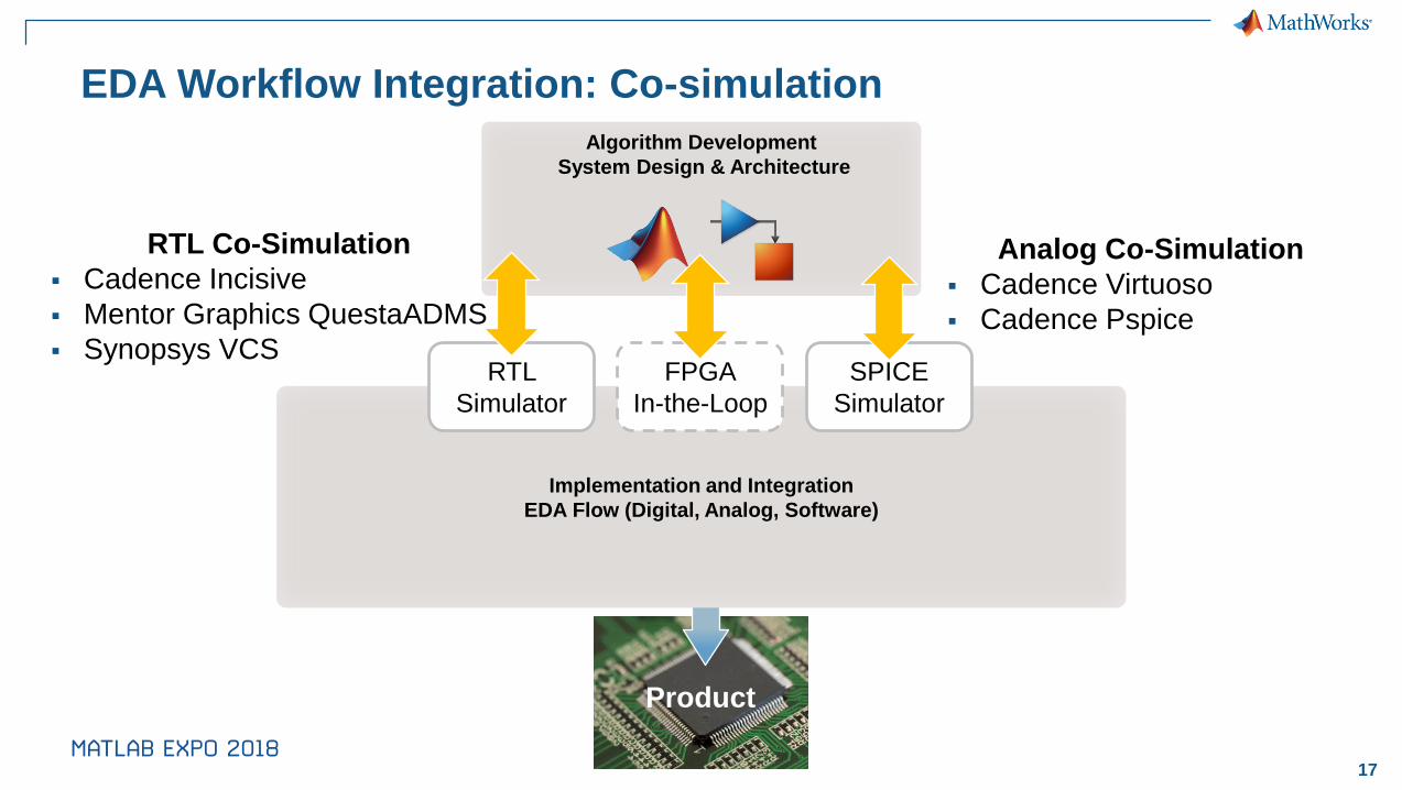
Product
Implementation and Integration
EDA Flow (Digital, Analog, Software)
EDA Workflow Integration: Co-simulation
RTL Co-Simulation
▪ Cadence Incisive
▪ Mentor Graphics QuestaADMS
▪ Synopsys VCS
Algorithm Development
System Design & Architecture
FPGA
In-the-Loop
SPICE
Simulator
RTL
Simulator
Analog Co-Simulation
▪ Cadence Virtuoso
▪ Cadence Pspice
18
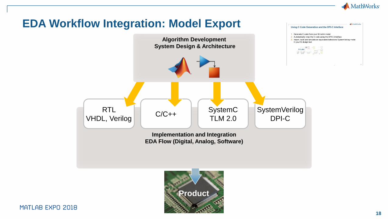
Product
Implementation and Integration
EDA Flow (Digital, Analog, Software)
EDA Workflow Integration: Model Export
RTL
VHDL, VerilogC/C++
SystemVerilog
DPI-C
SystemC
TLM 2.0
Algorithm Development
System Design & Architecture
19
Two Complementary Verification Approaches
Analog / Digital co-simulation
▪ Test your IP within the context of a full system simulation
▪ Use the visualization and analysis capabilities of Simulink and MATLAB
▪ Test each module independently of other modules
▪ Validate the IP behavioral model and speed up system-level simulation
SystemVerilog (DPI-C) code generation
▪ Fast simulation using the native SystemVerilog API
▪ HDL simulator independent
▪ Real number models for analog and digital IPs
▪ Most suitable for testbench generation and IC verification (regression tests)

20
Agenda
✓ Current Trends in Semiconductor Design and Verification
✓ System Level Design of Analog and Mixed-Signal Components
✓ Linking Behavioral to Circuit design and Verifying AMS designs
▪ Conclusion
21
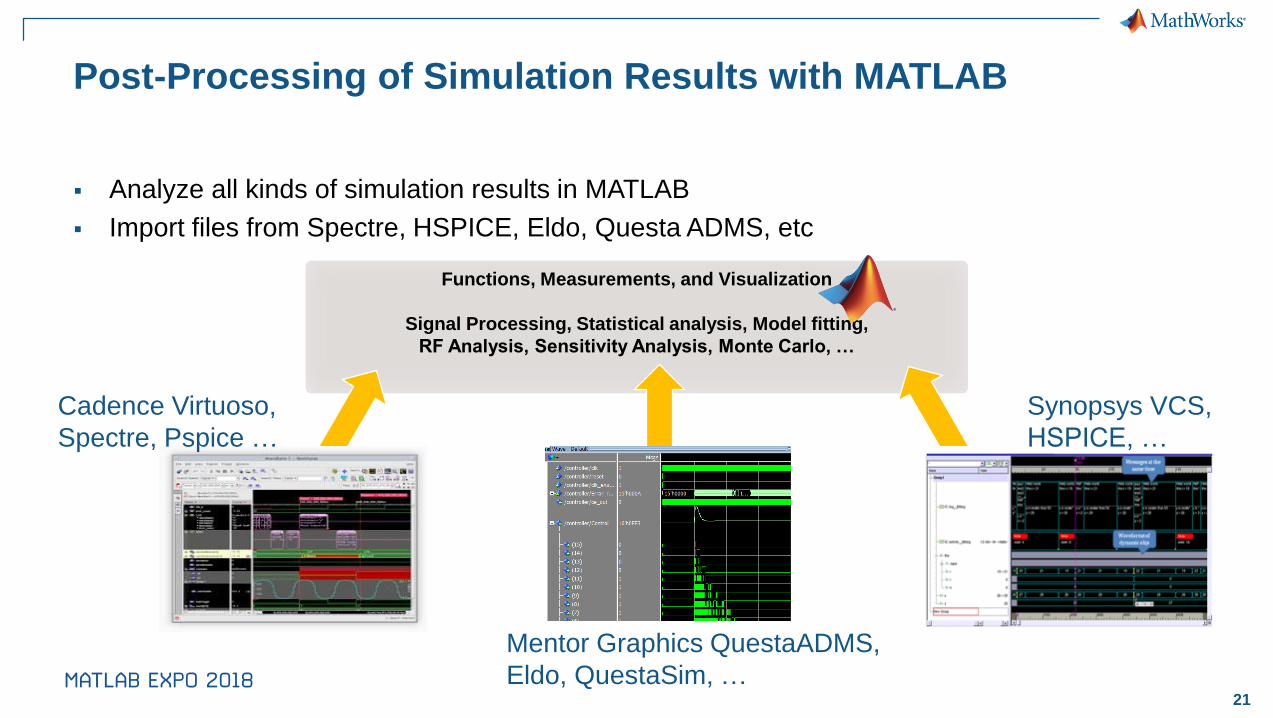
Post-Processing of Simulation Results with MATLAB
▪ Analyze all kinds of simulation results in MATLAB
▪ Import files from Spectre, HSPICE, Eldo, Questa ADMS, etc
Functions, Measurements, and Visualization
Signal Processing, Statistical analysis, Model fitting,
RF Analysis, Sensitivity Analysis, Monte Carlo, …
Cadence Virtuoso,
Spectre, Pspice …
Mentor Graphics QuestaADMS,
Eldo, QuestaSim, …
Synopsys VCS,
HSPICE, …

22
Cadence MathWorks Integration for Advanced Data Analytics
▪ Cadence ADE XL interface to MATLAB in latest MMSIM
– Enables Simulation data to be seamlessly transferred into MATLAB Environment
– Leverage MATLAB advanced data analysis capabilities to post-process and verify
simulation results
– Cadence Newsroom LinkCadence Virtuoso ADE-XL
23
Agenda
✓ Current Trends in Semiconductor Design and Verification
✓ System Level Design of Analog and Mixed-Signal Components
✓ Linking Behavioral to Circuit design and Verifying AMS designs
✓ Post-processing of simulation data
24
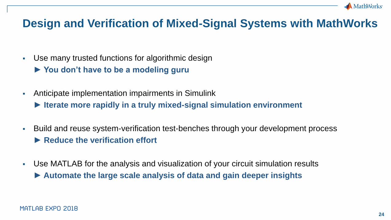
Design and Verification of Mixed-Signal Systems with MathWorks
▪ Use many trusted functions for algorithmic design
► You don’t have to be a modeling guru
▪ Anticipate implementation impairments in Simulink
► Iterate more rapidly in a truly mixed-signal simulation environment
▪ Build and reuse system-verification test-benches through your development process
► Reduce the verification effort
▪ Use MATLAB for the analysis and visualization of your circuit simulation results
► Automate the large scale analysis of data and gain deeper insights
25
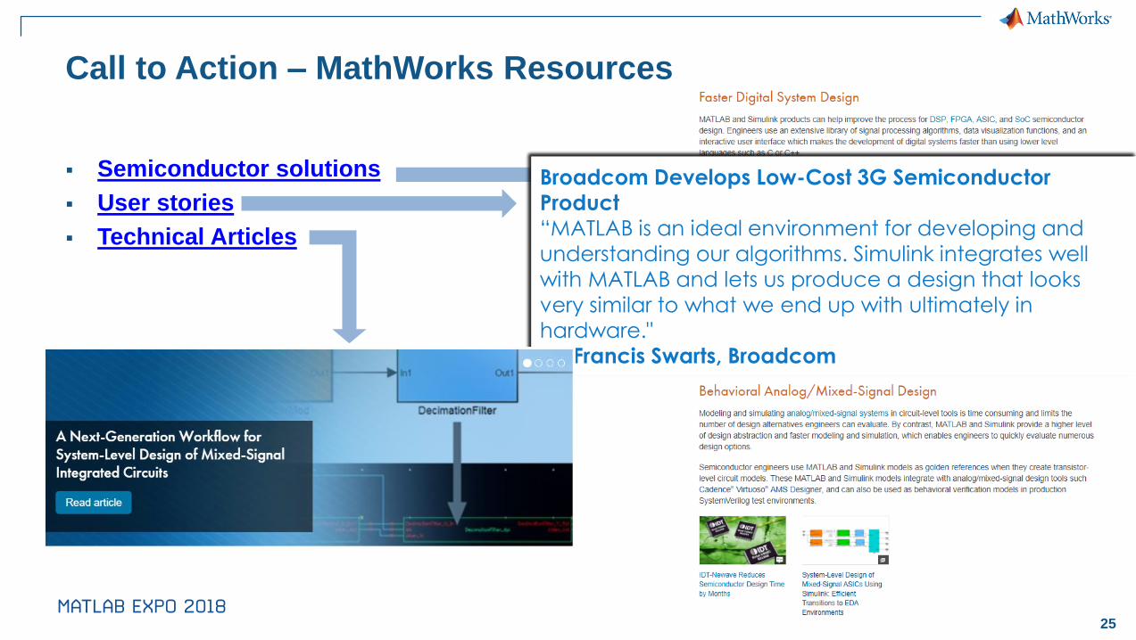
Call to Action – MathWorks Resources
▪ Semiconductor solutions
▪ User stories
▪ Technical Articles
Realtek Semiconductor Cuts Development Time by 50% and Takes the Lead in New-Generation HDA Codecs"MATLAB and Simulink helped us break through every
critical issue and complete the tasks before the projected deadlines. Our new streamlined design
process ensures our leadership position in a highly competitive market."— Shih Yu Ku, Realtek Semiconductor Corporation
Fujitsu Develops and Tests State-of-the-Art 40 GbpsOptical Transponder“By including circuit-level simulation results in our Simulink
models we can simulate millions of cycles with the accuracy needed to account for noise and other
transient effects. Simulink is the only tool fast enough for our jitter-tolerance simulations.”— William Walker, Fujitsu Laboratories of America
Epson Toyocom Designs and Verifies Mixed-Signal Integrated Circuit in Two Months “Circuit-level simulations took three days. With Verilog-A they took 20 minutes—still
too long to enable sufficient exploration of design alternatives. Using MATLAB and Simulink, we reduced
simulation time to just one minute.”
Jun Uehara, Epson Toyocom
Broadcom Develops Low-Cost 3G Semiconductor Product“MATLAB is an ideal environment for developing and
understanding our algorithms. Simulink integrates well with MATLAB and lets us produce a design that looks
very similar to what we end up with ultimately in hardware."— Francis Swarts, Broadcom
26
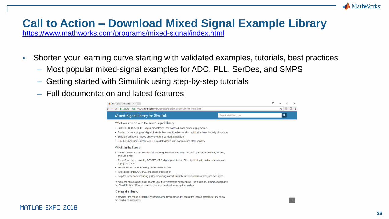
Call to Action – Download Mixed Signal Example Library
▪ Shorten your learning curve starting with validated examples, tutorials, best practices
– Most popular mixed-signal examples for ADC, PLL, SerDes, and SMPS
– Getting started with Simulink using step-by-step tutorials
– Full documentation and latest features
https://www.mathworks.com/programs/mixed-signal/index.html

27
Call to Action – MATLAB Central File Exchange
▪ An open exchange for the MATLAB and Simulink user community
– Get answers, challenge yourself and others, and share your knowledge
– Tap into the knowledge and experience of over 100,000 community members and
MathWorks employees.
https://www.mathworks.com/matlabcentral/fileexchange/
28
• Share your experience with MATLAB & Simulink on Social Media
▪ Use #MATLABEXPO
▪ I use #MATLAB because……………………… Attending #MATLABEXPO▪ Examples
▪ I use #MATLAB because it helps me be a data scientist! Attending #MATLABEXPO
▪ Learning new capabilities in #MATLAB and #Simulink at #MATLABEXPO.
• Share your session feedback: Please fill in your feedback for this session in the feedback form
Speaker Details
Email: [email protected]
LinkedIn:
https://www.linkedin.com/in/aniruddhadayalu
Contact MathWorks India
Products/Training Enquiry Booth
Call: 080-6632-6000
Email: [email protected]