design and structural analysis of an elliptical skylight
TRANSCRIPT
DESIGN AND STRUCTURAL ANALYSIS OF AN ELLIPTICALSKYLIGHT
by
Corey M. Smith
Bachelor of Science in Mathematics and PhysicsBates College
May 1999
SUBMITTED TO THE DEPARTMENT OF CIVIL AND ENVIRONMENTALENGINEERING IN PARTIAL FULFILLMENT OF THE REQUIREMENTS FOR THE
DEGREE OF
MASTER OF ENGINEERINGIN CIVIL AND ENVIRONMENTAL ENGINEERING
at
MASSACHUSETTS INSTITUTE OF TECHNOLOGYJune 2001
© 2001 Corey M. SmithAll Rights Reserved
MASSACHUSETTS INSTITUTEOF TECHNOLOGY
JUN 0 4 2001L0B
LIBRARIES
%iE/R
The author hereby grants MIT permission to reproduce and distribute publicly paper andelectronic copies of this thesis document in whole or in part
Signature of Author-Department of Civil/and Environmental Engineering
May 11, 2001A
Certified by
A1 -I
L1,,1 %,-Jerome J. Connor
Professor of Civil and Environmental EngineeringThesis Supervisor
Accepted by-Oral Buyukozturk
Chairman, Departmental Committee on Graduate Studies

DESIGN AND STRUCTURAL ANALYSIS OF AN ELLIPTICALSKYLIGHT
by
Corey M. Smith
Submitted to the Department of Civil and Environmental Engineering in PartialFulfillment of the Requirements for the Degree of Master of Engineering
in Civil and Environmental Engineering at the Massachusetts Institute of TechnologyJune 2001
Abstract
Over the course of the academic year 2000-2001 a Master of Engineering project wascompleted by a group of six students. The project addressed the problem MIT is facingwith limited space on campus to store books. A new underground library was designed toremedy the problem. The design considered all aspects relating to the design andconstruction of the new library. One of the components of the design was to be a largeelliptical skylight over the top of a portion of the library.
This thesis takes the concept of the elliptical skylight further than time allowed during theproject. First, a more detailed description of the underground library is presented. Then,an overview of the the skylight is discussed. After this, the actual design of the skylight isundertaken. This portion begins with a discussion of the design criteria that needed to beaddressed. Then, a geometric model was created on the structural analysis programSAP2000. To this model, realistic loads were applied, and the resulting element forceswere analzed. Finally a discussion of the buckling of thin shells was included, and thetheory was included in the design as a final check of the dome's stability.
Thesis Supervisor: Jerome J. ConnorTitle: Professor of Civil and Environmental Engineering

ACKNOWLEDGEMENTS
I would like to thank a couple of people for making this thesis, and almost everythingelse this year, possible.
Professor Connor, for his guidance and encouragement
Kate, for supporting me in every way
MASSACHUSETTS INSTITUTE OF TECHNOLOGY 3

Table of Contents
CHAPTER 1 INTRODUCTION 6
CHAPTER 2 OVERVIEW OF THE UNDERGROUND LIBRARY 7
CHAPTER 3 OVERVIEW OF THE ELLIPTICAL SKYLIGHT 10
CHAPTER 4
CHAPTER 5
DESIGN CRITERIA
DEVELOPMENT OF THE SAP 2000 MODEL
5.1 GEOMETRIC DEFINITION
5.2 LOADING
5.3 DEAD LOAD
5.4 WIND LOAD
5.5 SNow LOAD
5.6 OUTPUT
CHAPTER 6 ANALYSIS OF RESULTS
MASSACHUSETTS INSTITUTE OF TECHNOLOGY
14
18
19
23
23
25
27
29
37
DESIGN CRITERIA
4

CHAPTER 7 BUCKLING OF THIN SHELLS
CHAPTER 8 CONCLUSION
APPENDIX 1: ELEMENT NUMBERS AND LENGTHS
APPENDIX 2: REFERENCES
MASSACHUSETTS INSTITUTE OF TECHNOLOGY
39
49
50
63
5

Chapter 1 Introduction
Over the course of the academic year 2000-2001 at MIT, a Master of Engineering project
was completed by a group of six students. The project addressed the problem MIT is
facing with limited space on campus to store books. A new underground library was
designed to remedy the problem. The design considered all aspects relating to the design
and construction of a new library on campus. One of the components of the design was to
be a large elliptical skylight over the top of a portion of the library. The intent of the
skylight was to bring light from above down to the first six floors of the library. It was a
key feature in the design, since it was intended to make the space hospitable.
This thesis takes the concept of the elliptical skylight further than time allowed on the
project. The design proposed herein is the end result of the consideration of many
framing possibilities. The result is a scheme, which makes sense both aesthetically and
structurally. In the following chapters the background of the project will be discussed in
more detail, and a detailed design will be undertaken.
MASSACHUSETTS INSTITUTE OF TECHNOLOGY 6

Chapter 2 Overview of the Underground Library
The success of any research-oriented educational institution is dependent, in part, on the
quality and size of its library system. Not only must the collections be pertinent and
complete, they must also exist in a useable state. The virtually endless amount of
information contained in the collection is useless if not readily accessible to the students,
researchers, and faculty who depend upon it for successful advancements in their field.
Figure 1 Location of Proposed Underground Library
The Underground Library Project addressed the current library space dilemma at the
Massachusetts Institute of Technology. The solution presented consisted of constructing a
new centralized library where all books currently stored off site could be relocated to,
while also providing more student usage space and ample expansion for future collection
growth. In addition, the new library would provide more flexibility in current libraries by
relieving the over crowdedness they are now experiencing.
MASSACHUSETTS INSTITUTE OF TECHNOLOGY 7

Figure 2 Alias Rendering of Underground Library with Building 54 in Background
The design project did not just look at a detailed structural design of a new on-campus
library, but examined all the issues relating to it. For example, the important library
issues were identified from the beginning through conferences with library staff and
campus administrators. Once the problem was clearly defined, the solution was tailored
to fit the needs of the MIT library system and student body. Considerations such as
aesthetics, access, layout, constructability, serviceability, and cost were all examined and
integrated into the design.
MASSACHUSETTS INSTITUTE OF TECHNOLOGY 8

-I
The resulting design called for a large cylindrical structure placed underground in
McDermott Court on the MIT campus. This location can be seen above in Figure 1. This
was decided to be the optimal location for such a structure, since it is in the center of
campus, near to most of the academic buildings and other existing libraries, and
McDermott court is extremely unlikely to every contain an above-ground structure since
it is one of the sacred green spaces on campus.
The necessary size for a new library was also carefully considered. In order to take half
the books from all on campus libraries, all of the books from off campus libraries, and
allow room for expansion, the needed size was determined to be approximately 250,000
square feet. The design called for nine floors each of about 30,000 square feet, plus a
tenth floor for utilities. The quality of floors was to increase as you went up toward the
surface, with the first floor housing the majority of staff workspace, including the
circulation desk. The first six floors were to be served natural light by means of a large
skylight over a central shaft extending down into the center of the library. The remaining
floors were designated primarily for dense book storage, and potentially compact
shelving. This space was not intended for study or workspace since it was not to have any
natural light.
As can be seen from the above discussion, the skylight is a key component to a successful
design. The concepts contributing to the skylight will be discussed in detail in the next
chapter.
MASSACHUSETTS INSTITUTE OF TECHNOLOGY 9

Chapter 3 Overview of the Elliptical Skylight
Figure 3 Alias Rendering of Elliptical Skylight
The architectural elliptical skylight to cover the library's central shaft serves the dual
purpose of maximizing light entry into the library, while providing an architectural
landmark on the MIT campus. The basic structural shape has two major components. On
the south side of the dome, the structure forms essentially a convex shell in compression,
while on the north side, the structure makes a concave shell in tension. The convex side
of the dome faces due south, in order to capture the maximum amount of sunlight. The
concave side is designed to partially reflect sunlight down into the library, which would
otherwise escape.
MASSACHUSETTS INSTITUTE OF TECHNOLOGY 10
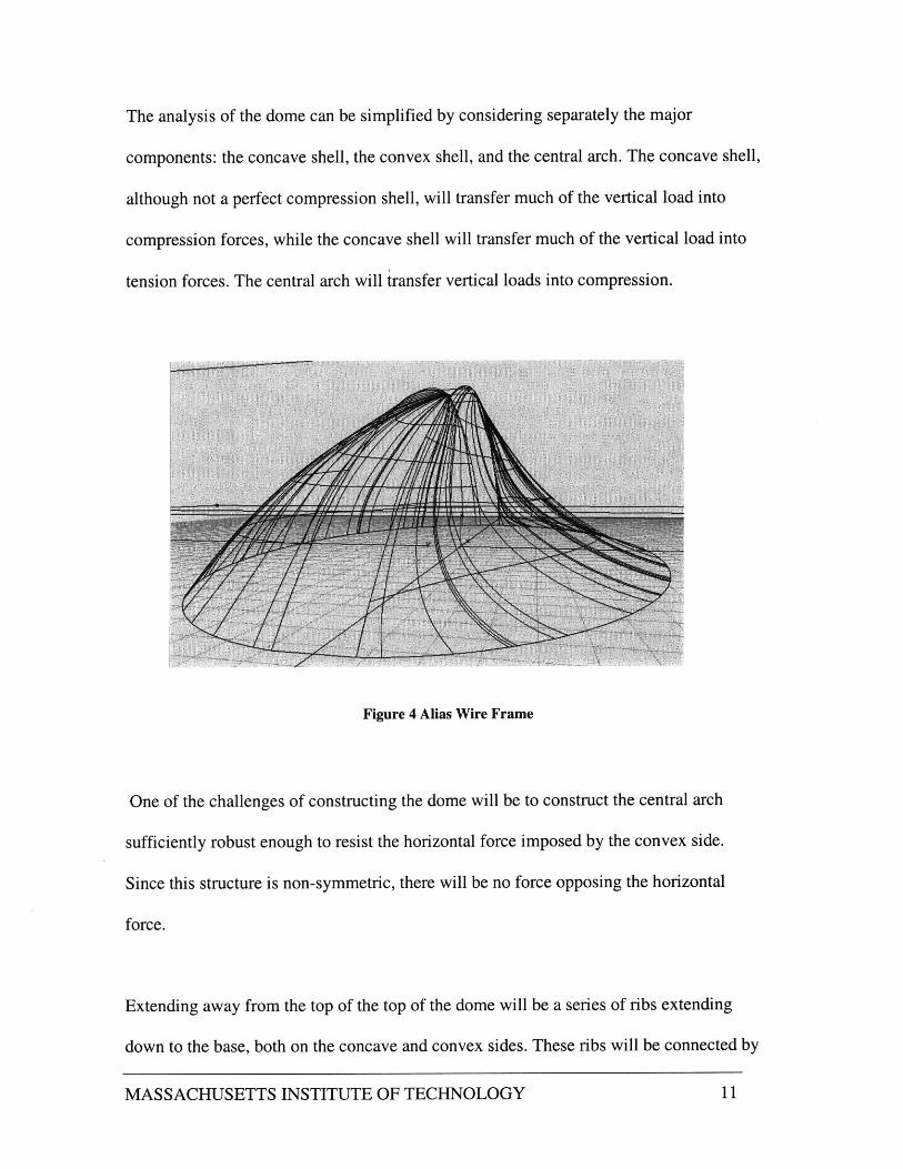
The analysis of the dome can be simplified by considering separately the major
components: the concave shell, the convex shell, and the central arch. The concave shell,
although not a perfect compression shell, will transfer much of the vertical load into
compression forces, while the concave shell will transfer much of the vertical load into
tension forces. The central arch will transfer vertical loads into compression.
Figure 4 Alias Wire Frame
One of the challenges of constructing the dome will be to construct the central arch
sufficiently robust enough to resist the horizontal force imposed by the convex side.
Since this structure is non-symmetric, there will be no force opposing the horizontal
force.
Extending away from the top of the top of the dome will be a series of ribs extending
down to the base, both on the concave and convex sides. These ribs will be connected by
MASSACHUSETTS INSTITUTE OF TECHNOLOGY 11

bracing elements, which will form triangular panels, into which the glass sections
described below will fit.
The glass faces of the dome are to be constructed from 12 mm float glass. This is the
thickness most often specified for high performance architectural applications, due to its
durability and relative lightweight. The individual glass pieces must be shaped and sized
so that they can fit within a 7-foot by 18-foot rectangle; this is the material application
limit currently accepted for this thickness of float glass. Structural sealant rather than
bolting will be used to affix the glass to the frame, as bolting can weaken the panes. A
specially treated type of float glass called "white glass" is usually used in architectural
applications (such as the Louvre pyramid). During production, most of the iron oxides
are removed form the glass, leaving it effectively colorless and non-reflective. However,
the prevalence of the steel frame in the design, as well as its asymmetry across the long
axis, requires a different approach. Cobalt oxide will be added to the glass during
processing, producing a blue-gray tint that will blend well with the steel frame. After
cooling, an anti-glare coating will be added. This is a transparent coating with a
thickness of one-fourth the wavelength of glass. The reflection of the treated glass will
be reduced from 11 percent to less than 2 percent (often less than one percent). The net
effect is of essentially non-reflective glass which blends, in color, with the steel frame.
MASSACHUSETTS INSTITUTE OF TECHNOLOGY 12

Figure 5 Example of Steel Frame and Triangular Glass Panels
Hollow rectangular steel sections will be used to construct the frame of the dome. All
connections will be fully welded to ensure that the frame is sufficiently rigid. Because of
the material restrictions discussed above, the individual glass sections will be triangles
about 7 feet on a side.
The overall size of the dome was determined by the size of the central shaft of the library.
Precise specifications for the design are provided in the following chapter.
MASSACHUSETTS INSTITUTE OF TECHNOLOGY 13

Chapter 4 Design Criteria
As the elliptical skylight is an integral part of the aesthetics and functioning of the
underground library, it was defined in many ways prior to its formal structural design. In
this way the design defined the structure. The design is not intended to be the most
efficient from a structural standpoint, but that deficit was decided to be worth it in light of
benefits gained in other areas.
The first major criterion was that the skylight must fit over the library's large central
shaft shown below. The central shaft of the library was designed to bring a large quantity
of light down to the first six floors. It was very important to provide adequate natural
light to the employees and students using the space in order to prevent a claustrophobic
feeling. Furthermore, the shaft was designed to be elliptical so that some sense of
orientation was provided. Being that the library was otherwise round it was felt that some
kind of directional cue was important. These conditions defined that the skylight has an
elliptical footprint of size 92 x 52 feet.
Elliptical Dome
McDermott Court
ShallowDeep
EgressEgress
Figure 6 Schematic of Library Central Shaft with Skylight
MASSACHUSETTS INSTITUTE OF TECHNOLOGY 14

Being that the primary goal of the skylight was to bring the maximum amount of light
into the library, it was very important to minimize the amount of framing steel, thereby
maximizing the total area of glass. This criterion was challenging to meet since the
chosen shape of the dome was to be in some ways structurally inefficient. Also, the
chosen framing pattern had to be visually harmonious since it would be highly visible
from inside the library as well as from the grounds outside.
The actual shape of the dome was chosen because it was decided that it would maximize
light entry into the library. This shape consisted of a convex quasi-spherical south facing
side, and a complex concave side facing north. For the following description, refer to
Figure 4. The concave side is more precisely shaped like a saddle since it has positive
curvature in one direction (longitudinal) and negative curvature in the other direction
(latitudinal). An arch that extends from east to west connects the two sides. The shape
was designed in this way to direct light down into the central shaft. Light that entered
from a low angle from the south and would otherwise escape to the north would instead
be reflected down into the shaft by the concave side.
Figure 7 Light Entry into Library
MASSACHUSETTS INSTITUTE OF TECHNOLOGY 15
From a structural point of view the shape is inefficient because the concave side does not
oppose the horizontal forces imposed on the central arch by the convex side. Rather, the
concave side in effect "hangs" from the central arch and provides no forces in the
horizontal direction. For this reason, the central arch is under a great deal of out of plane
bending stress that it must transmit to the base in the form of bending moments. On the
other hand many aspects of the design are efficient. Namely, the internal stresses on the
convex side are mainly compressive, while those on the concave side are mainly tension
stresses. Also the central arch is transmitting the vertical forces applied to it largely
through compression.
The last requirement for design is imposed by limitations on glass. First of all, each glass
piece will be planar, and therefore must be supported by a group of planar frame sections.
Secondly there is a limitation on the size of the glass pieces, namely that each must fit
within a rectangle of size approximately 7 x 18 feet. This restriction on size did not
restrict the overall design, since small sections were already necessary to approximate an
overall curved looking surface. To simplify the planar requirement, it was decided that
each section would be triangular, and would sit on three straight hollow steel sections.
Since any three straight-line segments define a plane, this guarantees that each piece of
glass will sit on a flat frame.
Framing the dome into many triangular sections ensures that it will act like a truss under
in-plane membrane forces. In other words, each triangle of the surface will deform in
plane only through compression and tension, which is the strongest possible arrangement.
MASSACHUSETTS INSTITUTE OF TECHNOLOGY 16
On the other hand, being that the design is essentially a thin shell, it must be
acknowledged that out-of-plane rigidities are relatively low, and buckling could be a
problem if it is not properly designed for.
Through careful design and analysis, the criteria and complications listed above will be
thoroughly handled.
MASSACHUSETTS INSTITUTE OF TECHNOLOGY 17
Chapter 5 Development of the SAP 2000 Model
In order to simplify the design process and to assist with the modeling, the structural
analysis program SAP2000 was used. Common advice regarding computer tools in
engineering states that if you put garbage in to the computer, only garbage will come out.
For this reason, it was very important to make sure that the dome was modeled with
geometric accuracy, and that realistic scaled forces were applied in the proper manner.
SAP2000 was used primarily to find internal frame forces, and support reactions. Being
that we are dealing with over 420 unique frame sections, performing calculations by hand
would provide approximate results at best and would be extremely tedious. As is the case
with much of engineering, quality results are only obtained after many design iterations,
and the same would hold true for the complete design of the dome. This thesis will not
find an optimal solution, but rather will complete a first iteration of design and arrive at
one reasonable solution.
At first, intuition was used to pick frame and glass sections so that an initial guess at the
forces and weights could be made. SAP2000 took as inputs these initial sections and
generated axial forces, torsion, moments, and shears, in each of the frame sections. The
glass sections were applied to the model, but were done so only to provide dead load, and
not to provide rigidity or bracing. The stresses generated were analyzed both in a local
and global sense in order to check for local material failure as well as global buckling.
These procedures will be discussed in more detail in the later chapters.
MASSACHUSETTS INSTITUTE OF TECHNOLOGY 18
5.1 Geometric Definition
The dome was defined geometrically in large part through the use of the equation of an
ellipse, and careful accounting done on Excel. In this way, the exact coordinates of each
point were derived, and than carefully imported into SAP2000. After this, the nodes were
connected with straight frame sections in a logical way. On SAP2000 the convex side
was first divided into sixteen circumferential segments each of equal angles. However,
since we were dealing with an ellipse, all segments were of different actual lengths, and
some adjustment was made. After careful adjustment, the convex side consisted of
fourteen segments radiating down and out from the top of the dome to the boundary
ellipse.
Each radial segment is itself an ellipse with one radius being the height of the dome, and
the other radius being the distance from the center of the base out to the point at which
the segment was to meet the boundary. These two radii were used as parameters for the
ellipse equation, and in this way each were custom defined mathematically. Eventually
each radial ellipse needed to be connected to its two neighbors circumferentially, so each
needed to have nodes with equal vertical spacing. For this reason, the vertical position of
each node was predefined and used as the independent variable in each custom ellipse
equation. Therefore the ellipse equations defined the horizontal position of each node.
MASSACHUSETTS INSTITUTE OF TECHNOLOGY 19

The concave side was a bit tricky to define at first, but after some careful thought a
reasonable solution was obtained. In particular the hang-up was thought to be the
interface, namely the central arch. How could a convex surface and a concave surface
meet smoothly at one interface? To solve the problem it was decided that unlike the
convex side, the concave ribs would not radiate outward from the top, but instead would
be parallel to each other and extend away from different points on the central arch.
Figure 8 Plan View of Nodes Showing Radial Layout and Parallel Layout
Each rib was still defined mathematically through the use of the equation of an upside-
down ellipse. Interestingly, since the central arch is the same shape as the boundary
ellipse, the two radii for each rib were the same. In other words, each ellipse on the
concave side is actually a circle segment. Similarly to the derivation of the nodes on the
convex side, the nodes on the concave side each had the same vertical position as their
two circumferential neighbors.
MASSACHUSETTS INSTITUTE OF TECHNOLOGY 20
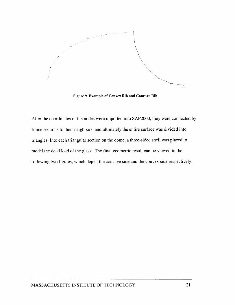
Figure 9 Example of Convex Rib and Concave Rib
After the coordinates of the nodes were imported into SAP2000, they were connected by
frame sections to their neighbors, and ultimately the entire surface was divided into
triangles. Into each triangular section on the dome, a three-sided shell was placed to
model the dead load of the glass. The final geometric result can be viewed in the
following two figures, which depict the concave side and the convex side respectively.
MASSACHUSETTS INSTITUTE OF TECHNOLOGY 21

Figure 10 Concave Side and Convex Side Showing Frames and Shells
MASSACHUSETTS INSTITUTE OF TECHNOLOGY 22

5.2 Loading
After the dome was defined geometrically on SAP2000, loads were applied to it
according to provisions set forth in the ASCE Standard "Minimum Design Loads for
Buildings and Other Structures." There were three major loads the structure would feel:
dead load, wind load, and snow load. Since no objects would be intentionally placed on
top of the dome, nor would any people reside on top of the dome, the live load for the
dome was taken to be zero. The load combination and factors to be applied to the dome
was taken to be combination number 4 from section 2.4.2 of the ASCE Standard, which
is as follows:
1.2D + 1.3W + 0.5L + 0.5(L, or S or R) where,D is the dead loadW is the wind loadL is the live loadLr is the roof live loadS is the snow loadR is the rain load
In our case, since S was assumed to be greater than L, or R, snow load was applied within
the parentheses. The derivations for dead load, D, wind load, W, and snow load S are
found in the following sections.
5.3 Dead Load
The dead load on SAP2000 was automatically applied in the negative global-z direction
upon assignment of real properties to frame elements and shells elements. As is explained
above, finding the precise dead load for a structure is in general an iterative process, as
MASSACHUSETTS INSTITUTE OF TECHNOLOGY 23

member sizes are often refined many times before the optimal configuration is reached.
To come to an initial guess for the size of the frame elements, similar dome projects were
researched, including the roof for the British Museum, which was recently designed by
Buro Happold in London. It appeared that in many cases, hollow steel sections were used
and were on the order of 3" x 6", for outside dimensions.
After the approximate initial size was determined, it was necessary to determine what
types of steel sections are commercially available. To do this, the AISC Manual of Steel
Construction was consulted. This reference lists many common types of steel sections as
well as many properties of the sections including weight, moments of inertia, cross-
sectional area, and maximum moment resistance to be used for design. The following
initial section was picked:
6 x 3 inch Rectangular Structural TubingThickness: 3/8 in.Fy: 46ksiCross-Sectional Area: 5.83in2
A template was used on SAP2000, which allowed the dimensions for hollow steel
sections to be specified. A snapshot of this template is shown here:
MASSACHUSETTS INSTITUTE OF TECHNOLOGY 24

S ection Name |HOLL 3
d~h (G) 10.5
(dri ~) 10.0313
Figure 11 Hollow Steel Section
The remainder of the dead load comes from the glass panels on the surface of the dome.
From literature on the properties of glass and the availability of certain types of glass, it
was found that, as discussed previously, that 12mm thick glass was strong enough to span
the distances between the chosen arrangement of frame elements. Since the intention is
for the glass panels to provide no contribution to the structural stiffness of the system, the
panels were added only to provide dead load to the structure. In reality, the glass panels
would provide bracing by way of diaphram action to the frame elements, but for
simplicity in this design that contribution was neglected, and frame elements were sized
such that they could take 100% of the stresses. Furthermore, in SAP2000, shell elements
are available in either steel or concrete, but since glass is 7% heavier than steel, steel
shells that were 7% thicker were used. The shell elements were added to each triangle on
the surface of the dome.
5.4 Wind Load
As is evident from "Minimum Design Loads for Buildings and Other Structures," wind
loads are difficult to accurately model for oddly shaped structures, such as domes. For
MASSACHUSETTS INSTITUTE OF TECHNOLOGY 25

I
this reason, some overestimating simplifications were made during design in order to
produce results without becoming bogged down in aerodynamics.
The wind pressure, qz, is in general calculated from the following formula:
q, = 0.00256 K, (IV)2, whereq, is the wind pressure at height z above the groundI is the importance factor and varies from 0.95 to 1.05Kz is the exposure coefficient, and is a function of z and exposure categoryV is the basic wind speed, which is 81mph in Boston. (ASCE, Chapter 6)
q, was calculated using z = 26ft (the maximum height of the dome), and each of the four
possible exposure categories: A,B,C,D. Exposure category ranges from A, buildings in
city centers with an abundance of wind shielding from other buildings, to D, highly
exposed buildings, such as those surrounded by water expanses. Obviously the maximum
wind pressure was found using exposure category D. As is well known on the MIT
campus, that McDermott Court, the proposed location for the dome, is in an excessively
windy area, where the surrounding buildings create a narrow passage through which the
air rushes as speeds much higher than normal. For this reason, and because of the
uniqueness of the proposed shape, exposure category D was used, and it was felt that this
would ensure an adequate safety factor. The resulting value for qz is as follows:
q, = 22.4 psf at 26 feet above the ground
To further simplify the design process, a uniform load of 22.4 psf was applied to the
south side of the entire structure, and this load was not varied over the height of the
structure. Since wind loading decreases lower to the ground, this was again adding safety
MASSACHUSETTS INSTITUTE OF TECHNOLOGY 26

to the design. The load was applied to the south side of the structure since that is the
prevailing wind direction, and the direction from which the structure is weakest. In
SAP2000, the wind load was applied to every shell element on the convex side of the
dome, with a factor of safety of 1.3, as decided above. The resulting load is shown in the
following figure:
Figure 12 Wind Load on Dome
5.5 Snow Load
The snow load was determined in a similar manner to the wind load: using the procedures
set forth in "Minimum Design Loads for Buildings and Other Structures." According to
MASSACHUSETTS INSTITUTE OF TECHNOLOGY 27

this manual, for the contiguous United States, snow load, pf can be found using the
following formula:
pf = 0.7 CeCt I pg, wherepy is the snow load in psfCe is an exposure factor which ranges from 0.8 to 1.2C, is a thermal factor which takes into consideration interior heat (1.0 - 1.2)I is an importance factor (0.8 - 1.0)
pg is the ground snow load (depends on location - Boston: 35psf)
Ce was taken to be 1.0, since the dome is in a moderately windy, but moderately sheltered
type location. Ct was taken to be 1.0 since the dome covers a heated space, and the
interior heat can be relied upon to reduce some of the potential snow load. Lastly I was
taken to be 1.2 since the library can be considered to be an "essential facility" and also to
increase the level of safety. Therefore, the snow load was found to be the following:
pf = 29.4 psf
On the SAP2000 model this load was applied with a factor of 0.5 (as designated in the
load combination chosen above) to the somewhat flat areas of the dome in the negative z
direction. The following figure shows the snow-loaded areas:
MASSACHUSETTS INSTITUTE OF TECHNOLOGY 28

Figure 13 Snow Load on Dome
5.6 Output
After applying the loads described above, the SAP2000 yielded the forces in each
member. As predicted, the majority of the forces felt by most members were axial forces
although in some cases substantial bending moments were felt. Certain critical areas were
identified in the output as having the highest axial forces and bending moments. So as to
simplify the design process, the member forces were analyzed in these areas, and since
they were critical, the remaining areas were decided to be sufficiently strong if they used
the same members. The critical areas for forces were seen to be the centers of the bases of
both the concave and convex sides, as well as much of the central arch. The following
MASSACHUSETTS INSTITUTE OF TECHNOLOGY 29

series of diagrams show the axial forces and bending moments for these three critical
areas:
Figure 14 Axial Forces on Convex Side
As can be seen from the figure above, the convex side of the structure experiences both
positive and negative axial forces under the effects of dead load, wind, and snow. The
highest axial force is found in element 3 and is 9.27 kips. This element is being stretched.
Element 5 is in compression and feels a force of -5.55 kips.
MASSACHUSETTS INSTITUTE OF TECHNOLOGY 30
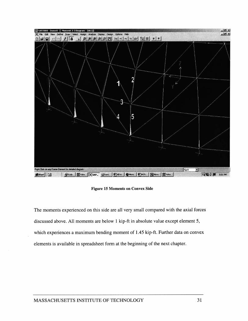
Figure 15 Moments on Convex Side
The moments experienced on this side are all very small compared with the axial forces
discussed above. All moments are below 1 kip-ft in absolute value except element 5,
which experiences a maximum bending moment of 1.45 kip-ft. Further data on convex
elements is available in spreadsheet form at the beginning of the next chapter.
MASSACHUSETTS INSTITUTE OF TECHNOLOGY 31

Figure 16 Axial Force on Concave Side
The values of axial force on the concave side range from 1.38 kips in element 8 to 5.51
kips in element 10. All elements on this side are in tension, as is expected. For this
reason, buckling is not a threat, and therefore the concave side will not be included in
buckling calculations later in this report.
MASSACHUSETTS INSTITUTE OF TECHNOLOGY 32

Figure 17 Moments on Concave Side
The moments on the concave side are all very small except in element 10. Element 10
experiences a maximum negative bending moment of -4.01 kip-ft. Further data on the
concave side is included in the spreadsheet in the following chapter.
MASSACHUSETTS INSTITUTE OF TECHNOLOGY 33

Figure 18 Axial Forces Near Base of Central Arch
As was predicted, the central arch experiences relatively high axial forces on the concave
side. In particular, element 11 is in compression, and feels a force of -22.48 kips.
Another issue is the axial force differential across the arch: the difference in axial force
from element 15 to element 17 is approximately 7 kips. This is the way the moment
imposed from the convex side has manifested itself. Also of note are the high axial
MASSACHUSETTS INSTITUTE OF TECHNOLOGY 34
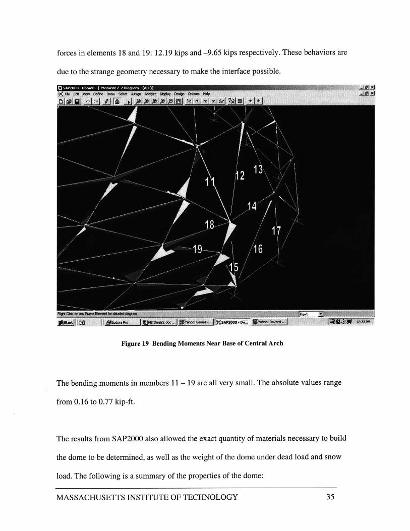
forces in elements 18 and 19: 12.19 kips and -9.65 kips respectively. These behaviors are
due to the strange geometry necessary to make the interface possible.
Figure 19 Bending Moments Near Base of Central Arch
The bending moments in members 11 - 19 are all very small. The absolute values range
from 0.16 to 0.77 kip-ft.
The results from SAP2000 also allowed the exact quantity of materials necessary to build
the dome to be determined, as well as the weight of the dome under dead load and snow
load. The following is a summary of the properties of the dome:
MASSACHUSETTS INSTITUTE OF TECHNOLOGY 35

Number of Steel Sections 422Total Length 3559 ftDensity 19.8 lbs/ftTotal Steel Weight 71 kips
Number of Glass Panels 271Total Area 7090 sq.f.Density 2.1 lbs/sq.fiTotal Glass Weight 15 kips
Total Dead Load 06 kips
Reaction Due to Snow Load(factored) 65 kipsI I _ 15 k _ps
Total Reaction 115 1 kips
Figure 20 Summary of Dome Properties
MASSACHUSETTS INSTITUTE OF TECHNOLOGY 36
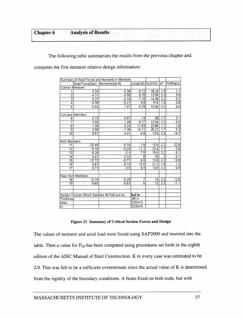
Chapter 6 Analysis of Results
The following table summarizes the results from the previous chapter and
computes the first iteration relative design information:
Summary of Axial Forces and Moments in Members|Axial Force(kips) Moments(kip-ft) Length(ft) KL(K=2) m* Peff(kips)
Convex Members1 0.33 -0.39 9.12 18.24 1.9 1.12 -4.31 -0.56 6.78 13.56 2.3 5.63 9.27 -0.18 7.18 14.36 2.2 9.74 -0.39 -0.21 9.8 19.6 1.9 0.85 -5.55 1.47 6.78 13.56 2.3 8.9
Concave Members6 2.15 0.57 14 28 1.7 3.17 3.56 1.28 6.77 13.54 2.3 6.58 1.38 0.24 11.93 23.86 1.7 1.89 2.98 -1.36 14.11 28.22 1.7 5.3
10 5.51 -4.01 6.8 13.6 2.3 14.7
Arch Members11 -22.48 -0.16 7.8 15.6 2.2 22.812 -0.18 -0.24 11.2 22.4 1.7 0.613 -5.26 -0.4 7.8 15.6 2.2 6.114 5.41 0.32 8 16 2 6.115 -12.72 -0.77 6.9 13.8 2.3 14.516 0.81 -0.19 10.6 21.2 1.8 1.217 -5.73 -0.5 6.9 13.8 2.3 6.9
Near Arch Members18 12.19 -0.29 7 14 2.2 12.819 -9.65 -0.63 6 12 2.3 11.1
Section Chosen Which Satisfies All Peff and KL: 6x3 inThickness: 3/8 inAre a: 5.83 inA2
x: 23.8 inA4
Figure 21 Summary of Critical Section Forces and Design
The values of moment and axial load were found using SAP2000 and inserted into the
table. Then a value for Peff has been computed using procedures set forth in the eighth
edition of the AISC Manual of Steel Construction. K in every case was estimated to be
2.0. This was felt to be a sufficient overestimate since the actual value of K is determined
from the rigidity of the boundary conditions. A beam fixed on both ends, but with
MASSACHUSETTS INSTITUTE OF TECHNOLOGY 37

rotation allowed has a K value of 1.0. The value of m* is then read off a table. m is a
conversion factor which multiplies the design moment, and gives an effective axial load.
The total effective axial load, Peff, is then:
Peff= Po + m* M
Then for every section being analyzed, Peff, and KL were compared with the value
allowed for a 6x3 inch hollow rectangular section, 3/8 inch thick. In every case, the 6x3
member was sufficient to resist the effective axial load.
MASSACHUSETTS INSTITUTE OF TECHNOLOGY 38

Chapter 7 Buckling of Thin Shells
A shell structure is defined as a structure whose primary mode of resistance is through in
plane forces including compression, tension, and shear. These types of structures are the
three-dimensional analog to the arch. The arch, as is commonly known, is an extremely
efficient structure since it transfers the majority of forces to the supports through
compression. Unless an arch is perfectly designed for the loading conditions, it will
experience some bending moments and shear. However, relative to compression, these
are generally insignificant. Similarly a shell will transmit the majority of the loading
through compression.
Figure 22 Large Framed Dome
MASSACHUSETTS INSTITUTE OF TECHNOLOGY 39

One of the dangers of designing a shell or arch is that if it is not properly analyzed it may
buckle, causing a system failure. It would seem that since the yield strength of steel is so
high, very little steel is necessary to take the compression forces. However, since arches
and domes are generally unbraced and span large distances, the amount of steel necessary
to prevent buckling may be the limiting factor in design. To better understand the issue
here, consider the design of a basic column. As an input parameter in choosing a column
size, the engineer must consider the effective length. This is because, as the effective
length increases, so does the threat of buckling. In other words, a long slender column
under compressive loads will fail because of buckling long before it fails by material
crushing.
Unlike designing the individual frame elements for a structure, which requires an
engineer to look at the structure under a magnifying glass, designing for buckling
requires the engineer to step back and look at the big picture. In other words, the
individual pieces must be forgotten and the structure as one unit must be considered. To
illustrate general buckling failure, consider the following diagram:
MASSACHUSETTS INSTITUTE OF TECHNOLOGY 40

U nlLuc k m-d Shel-
Figure 23 Buckling Failure
The convex side of the dome being considered in this paper is an example of a latticed or
reticulated shell, which is defined as being the form resulting from approximating a solid
shell surface by a framework or relatively short linear structural shapes. Furthermore, to
simplify the analysis, the convex side is being approximated as spherical, with a radius of
curvature of 46 feet. Since this is the upper bound for radii, and critical buckling stress
decreases with increasing radius, choosing 46 feet is designing for worst-case conditions.
The following formula relates several factors to the minimum buckling stress:
MASSACHUSETTS INSTITUTE OF TECHNOLOGY 41

2 3
crrR = -0.54A -0.145 9. A +3.0ilEtm tm T t
S2 where+ A A t) t
+ 1.09 -0.03 9.9 +3.08 +0.359LJ
O cr is the critical buckling stress
R is the radius of curvature17 is the plasticity reduction factorE is the modulus of elasticity of steeltm is the effective membrane thickness
tb is the effective bending thickness
A is the maximum imperfection and deflection (in practical shells 0.18 is used)
Note that some shells may have two different effective thicknesses depending on the
direction in which you are concerned. The above equation assumes that tml = tm2 and tbl=
tb2.
Determining tml and tm2 for shells framed in a rectilinear manner such as the one depicted
below is a simple matter.
TOP VIEW~dz A1,111
]j 1 T-
PLAN VIEW
-OPENA2V 2
c11DE VIE:-W
Figure 24 Reticulated Dome Framing Scheme
MASSACHUSETTS INSTITUTE OF TECHNOLOGY 42

To find the values for tml, i.e., tm in the horizontal direction, one need only divide the area
of each steel frame element extending horizontally by the spacing between the elements.
Applying this reasoning we get the following:
A1
""diAl
tm2 = A222
Alternatively to the membrane thickness, the bending thickness, thi and tb2 are essentially
measures of the bending rigidity of the shell. For this reason, the moments of inertia in
the respective directions are needed. Again, in the rectilinear case, as shown above, this
calculation is simple:
123tbl = Kd11
tb2 = K2b2d2
The shell being analyzed here is slightly more complicated. Consider the following
typical convex surface section.
MASSACHUSETTS INSTITUTE OF TECHNOLOGY 43

Figure 25 Typical Surface Section
As you can see, there is a fairly regular pattern of steel in the horizontal (longitudinal)
direction and in the vertical (latitudinal) direction. However, there is also a crossbar
dividing each rectangle into two triangles. Components of the area and moment of inertia
of this crossbar must be included in the tm and tb calculations, as they do increase the
membrane and bending thicknesses respectively. Another complication at hand is the
fact that there are essentially six such sections of various sizes. For design simplicity, the
frame will not be varied in size over the surface of the convex dome. Therefore, the
buckling analysis will consider the bottom most section of the six, since it has the largest
element spacing, and thereby the lowest values of tm and tb. In this way, as we have done
before, we are designing for the worst case.
MASSACHUSETTS INSTITUTE OF TECHNOLOGY 44

First consider the membrane thickness tm, the thickness in the vertical direction. In each
section the stretching is resisted by one vertical member and one crossbar. Assume the
angle between the two is theta, as is shown in Figure 25. If the vertical member stretches
by a distance E, the crossbar will stretch by a distance Ecos(O). Therefore if the area of
steel in the vertical member is A, then the effective steel in the crossbar is Acos(O). The
total effective area of steel in the vertical direction is:
Al = A(] + cos(O))
If the spacing between such vertical member-crossbar pairs is di, then the effective
membrane thickness in the vertical direction is:
A (1+ cos(6))ml tM1 - di
Similarly, if the spacing between horizontal pairs is d2 (but 0 remains the same) , then the
effective area of steel in the horizontal direction and the effective membrane thickness in
the horizontal direction are respectively:
A2 = A(1 + sin(O))
t - A(1 + sin(6))m2 ~ d2
MASSACHUSETTS INSTITUTE OF TECHNOLOGY 45

The effective moments of inertia for horizontal and vertical bending can be derived in the
same way. If I is the moment of inertia for the steel members, then I1 and I2 are the
following:
I] = I(1 + cos(O))
I2 = I(1 + sin(6))
Thus, the effective bending thicknesses are the following:
tbl = 121(1 + cos(O)di
121 (1+sin(O)1/ 3
tb2 -d
Notice in Figure 25 that the angle 0 is approximately 45 degrees. The following figure
demonstrates the application of the above theory to our dome.
MASSACHUSETTS INSTITUTE OF TECHNOLOGY 46

Figure 26 Buckling Calculations
0 cr is calculated in the above Excel spreadsheet. In the first calculation, q was taken to be
1 since it was assumed that a was well below crcr. Furthermore, A was taken to be 0.18 as
suggested by Buchert. This results in an extremely high result. The second calculation
was intended to be a significant underestimate of (cT. A was taken to be 10 inches, which
was a good deal higher than the A given in any example given by Buchert. Furthermore,
rl was reduced to 0.5, a value well below that which would be expected. Even with the
MASSACHUSETTS INSTITUTE OF TECHNOLOGY
Buckling Calculation
I = 23.8 in^4 tm= 0.118481 ind= 84 in tb= 1.797132 inA= 5.83 in^2theta= 0.785398163 tb/tm 15.16806delta = 1 deltaAm= 8.440148E= 29000000 psieta= 1R =552 in
sigcr*R / (eta*E*tm) = 16.02626sigcr= 99756.46 psi
Underestimate1= 23.8 inA4 tm= 0.118481 ind = 84 In tb= 1.797132 inA = 6.83 inA2theta = 0.785398163 tb/tm 15.16806delta = 10 deltaAm 84.40148E = 29000000 psieta= 0.5R 552 in
sigcr*R /(eta*E*tm) 4.166967sigcr= 12968.77 psi
Actual Frame Force= 6000 poundsActual Frame Pressure = 1029.16 psi
Factor of Safety= 12.60133
47

overestimate, we find that the safety factor for buckling is over 12, implying that
buckling is really not a serious threat in our case.
It can be concluded from the analysis in this chapter that given the frame sections we
have chosen, and the radius of curvature of our dome, that buckling could not possibly
occur on the convex side.
MASSACHUSETTS INSTITUTE OF TECHNOLOGY 48

Chapter 8 Conclusion
The elliptical skylight designed to cover a portion of the proposed Underground Library
was an essential part of the overall design. Without a reliable, functioning skylight the
library would become essentially inhospitable, and therefore all the effort put into other
areas would have been done in vain.
The preceding chapters, perhaps were not excessively detailed or optimization oriented,
but did serve to prove the fact that the proposed elliptical skylight would be a reasonable
structure to build. Much time was spent prior to writing, considering and contemplating
the complex shape of the dome and deciding on a basic approach for how to build it.
Since the shape was decided upon before the framework, it was a substantial portion of
this project to determine a framing pattern that would be both functional and aesthetically
pleasing.
As stated before, the result was arrived at using mathematical formulas, careful
accounting, and intuition. It turned out to be a very harmonious structural layout. At this
point the challenge became trying to analyze the structure for stability. Because of the
extremely complex nature of the shape, this at first seemed to be a daunting task.
However, after some careful thought, a few reasonable assumptions were made which
simplified the whole process. In the end the chosen framing scheme was found to be
structurally acceptable.
MASSACHUSETTS INSTITUTE OF TECHNOLOGY 49

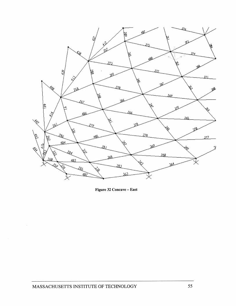
Appendix 1 : Element Numbers and Lengths
Element numbers can be identified in the following series of figures:
014
Figure 27 Convex - East
MASSACHUSETTS INSTITUTE OF TECHNOLOGY 50

455
Figure 28 Convex - West
MASSACHUSETTS INSTITUTE OF TECHNOLOGY 51

4J I
A.
Figure 29 Arch - West
MASSACHUSETTS INSTITUTE OF TECHNOLOGY 52

cli
14
438
440
Mi W
44;)
444
Figure 30 Arch - East
MASSACHUSETTS INSTITUTE OF TECHNOLOGY 53

1/ 427
Lr)
2C
Figure 31 Arch - Top
MASSACHUSETTS INSTITUTE OF TECHNOLOGY
125
rj
-,9-
434
rvn
54
191
Aeb 276277
2 0
3
Figure 32 Concave - East
MASSACHUSETTS INSTITUTE OF TECHNOLOGY 55

Figure 33 Concave - Center
MASSACHUSETTS INSTITUTE OF TECHNOLOGY 56

Figure 34 Concave - West
MASSACHUSETTS INSTITUTE OF TECHNOLOGY 57

Frame # Length(ft)2 9.0163 9.2114 8.6465 7.6016 8.6157 7.4478 6.9069 8.712
10 8.89411 8.3512 7.34113 8.32314 7.18615 6.67616 7.80117 7.98116 7.48819 6.568320 7.45621 6.44822 5.98623 6.37424 6.51725 6.11126 5.37827 6.0928 5.26529 4.88530 4.49931 4.61332 4.317
Frame # Length(ft)33 3.80734 4.30735 3.72236 3.45345 10.04946 8.85647 7.66948 6.89749 10.4350 10.02551 9.29852 8.34953 7.43954 6.86857 8.47758 7.8259 7.21860 6.83961 8.33562 8.14463 7.81964 7.38865 7.04766 6.81869 7.21970 7.03371 6.94472 6.92173 6.89174 6.84775 6.811
Frame # Length(ft)76 6.79179 6.79680 6.78981 6.78482 6.78983 11.94384 11.37985 10.486 9.06887 7.77688 6.91189 6.88290 6.80291 5.50592 8.44193 7.45394 8.34695 678796 9.14297 9.54798 9.12199 8.293
100 7.522102 8.466103 7.484104 7.113106 7.722108 9.808109 9.558110 7.857111 7.97
MASSACHUSETTS INSTITUTE OF TECHNOLOGY 58

Frame #1121131141151161171181191201221231241251261271281291301311321331341351361371381391 40141142143
Length(ft)9.6959.2469.114
10.65310.537
8.7248.3088.988
11.00610.388
9.83110.5
10.8510.63910.993
9.0169.2118.6467.6018.6157.4476.9068.7128.8948.35
7.3418.3237.1866.6767.8017.981
MASSACHUSETTS INSTITUTE OF TECHNOLOGY
Frame# Length(ft)144 7.488145 6.583146 7.456147 6.448148 5.986149 6.374150 6.517151 6.111152 5.378153 6.09154 5.265155 4.8865156 4.499157 4.613158 4.317159 3.807160 4.307161 3.722162 3.453172 10.049173 8.856174 7.669175 6.897176 10.43177 10.025178 9.298179 8.349180 7.439181 6.868184 8.477185 7.82
Frame# Length(ft)186 7.218187 6.839188 8.335189 8.144190 7.819191 7.388192 7.047193 6.818196 7.219197 7.033198 6.944199 6.921200 6.891201 6.847202 6.811203 6.791204 6.781205 6.796206 6.77207 6.803208 5.44209 3.259210 11.943211 11.379212 10.4213 9.068214 7.776215 6.911216 6.882217 6.802218 8.441
59

Frame #219220221222223224225227228229231233234235236237238239240241242243244245247248249250251252253
MASSACHUSETTS INSTITUTE OF TECHNOLOGY
L ength(ft)7.4538.3469.1429.5479.1218.2937.5228.4667.4847.1137.7229.8089.55687.8657
7.979.6959.2469.114
10.65310.537
8.7248.3068.988
11.00610.388
9.83110.5
10.8510.63910.993
5.88
Frame #254255256257258259260261262263264265266267268269270271272273274275276277278279280281283284285
Length(ft)6.7885.88
3.2599.5847.3446.9113.8364.8283.3563.908
14.11313.90412.542
9.71314.00513.605
11.9713.92513.28611.15413.82213.05113.74714.21513.12410.58613.69911.56112.499
9.1210.696
Frame # Length(ft)286 6.994287 11.567288 13.294289 13.294290 13.747291 13.822292 13.051293 13.925294 13.286295 11.154296 9.584297 5.44298 7.344299 5.505300 11.567301 14.005302 13.605303 11.97304 14.113305 13.904306 12.542307 9.713308 14.215309 3.634310 3.461311 13.124312 5.102313 4.872314 4.81315 10.586316 6.008
60

Frame #317318319320321322323324325326327328329330331332333334335336337338339340341342343344345346347
MASSACHUSETTS INSTITUTE OF TECHNOLOGY
L ength(ft)5.8545.73
5.72113.6996.5446.4316.3816.3166.333
11.5616.7216.6926.6996.6496.689
12.4993.6343.4614.8285.1024.872
4.813.3566.0085.854
5.735.7216.9116.5446.4316.381
Frame #348349350351352353354355356357358359360361362363364365366367368369370371372373374375376377378
Length(ft)6.3166.333
86.7216.6926.6996.6496.6896.994
9.127.7769.068
10.411.37910.696
9.06810.4
11.37911.94311.943
8.55310.16911.30211.93511.93511.30210.1698.5536.7123.8369.963
Frame # Length(ft)379 11.236380 11.927381 11.927382 11.236383 9.963384 8.083385 5.668386 9.78387 11.175388 11.921389 11.921390 11.175391 9.78392 7.658393 11.916394 11.916395 11.125396 9.629397 11.912398 11.089399 9.629400 11.125401 3.908402 7.776403 6.712404 5.668405 8.083406 7.658407 11.089408 11.912409 11.943
61

Frame# Length(ft)410 11.943411 11.379412 10.4413 9.068414 7.776415 6.911416 11.379417 10.4418 9.068419 7.776420 6.911421 8422 11.157423 6424 10.572425 6426 14.376427 8428 13.91429 8430 13.121431 6432 12.093433 14.375434 8435 13.91436 8437 13.121438 8439 12.093440 8
Frame# Length(ft)441 11.157442 8443 10.572444 8451 7.079452 7.079455 3.58462 4.146464 4.186466 4.602474 10.478475 7.971476 7.834477 4.602478 4.186479 4.146480 10.478481 7.971482 7.834
Figure 35 Frame Numbers and Lengths
MASSACHUSETTS INSTITUTE OF TECHNOLOGY 62

Appendix 2: References
Buchert, Kenneth P. Buckling of Shell and Shell-Like Structures: For Engineers,Architects, Fabricators, Builders, and Designers. K.P. Buchert & Associates, Columbia,Missouri, 1973.
Button, David and Pye, Brian. Glass in Buildings.Pilkington Glass, Ltd., 1993.
Makowski, Z.S.. Analysis, Design, and Construction of Braced Domes.Granada Publishing, Ltd, London. 1984.
Schittich, Staib, Balkow, Schuler, and Sobek. Glass Construction Manual. Birkhauser -Publishers For Architecture, Basel, Switzerland. 1999.
AISC: Manual of Steel Construction: Eighth Edition. American Institute of SteelConstructors, Inc. Chicago, IL, 1980.
ASCE Standard: Minimum Design Loads for Buildings and Other Structures. AmericanSociety of Civil Engineers, New York, NY, 1990.
SAP2000 NonLinear Version 6.13: Structural Analysis Program. Copyright 1984-1998Computers and Structures, Inc. Berkeley, CA
Subterranean Library at MIT: A Solution for the 2 1st Century. MIT Department of Civiland Environmental Engineering, Master of Engineering Program,Geotechnology Group,2001.
www.burohappold.com
MASSACHUSETTS INSTITUTE OF TECHNOLOGY 63

MASSACHUSETTS INSTITUTE OF TECHNOLOGY 64