design and simulation-based optimization of cooling...
TRANSCRIPT

2
Design and Simulation-Based Optimization of Cooling Channels for Plastic Injection Mold
Hong-Seok Park and Xuan-Phuong Dang University of Ulsan
South Korea
1. Introduction
Injection molding has been the most popular method for making plastic products due to high efficiency and manufacturability. The injection molding process includes three significant stages: filling and packing stage, cooling stage, and ejection stage. Among these stages, cooling stage is very important one because it mainly affects the productivity and molding quality. Normally, 70%~80% of the molding cycle is taken up by cooling stage. An appropriate cooling channels design can considerably reduce the cooling time and increase the productivity of the injection molding process. On the other hand, an efficient cooling system which achieves a uniform temperature distribution can minimize the undesired defects that influence the quality of molded part such as hot spots, sink marks, differential shrinkage, thermal residual stress, and warpage (Chen et al., 2000; Wang & Young, 2005).
Traditionally, mold cooling design is still mainly based on practical knowledge and designers’ experience. This method is simple and may be efficient in practice; however, this approach becomes less feasible when the molded part becomes more complex and a high cooling efficiency is required. This method does not always ensure the optimum design or appropriate parameters value. Therefore, many researchers have proposed some optimization methods to tackle this problem. Choosing which optimization method was used mainly depends on the experience and subjective choice of each author. Therefore, finding appropriate optimization techniques for optimizing cooling channels for injection molding are necessary.
This book chapter aims to show the design optimization method for designing cooling
channels for plastic injection molds. Both conventional straight-drilled cooling channels and
novel conformal cooling channels are focused. The complication of the heat transfer process
in the mold makes the analysis to be difficult when using the analytical method only.
Therefore, using numerical simulation tools or combination of analytical and numerical
simulation approach is one of the intelligent choices applied to modern mold cooling
design.
The contents of this book chapter are organized as follows. Cooling channels layout and the
foundation of heat transfer process happening in the plastic injection mold are presented
systematically. Physical and mathematical modelings of the cooling channels are also
introduced. This section supports the reader the basic governing equations related to the
www.intechopen.com
New Technologies – Trends, Innovations and Research
20
cooling process and how to build an appropriate simulation model. Subsequently, the
simulation-based optimizations of cooling channels are presented. In this section, the state-
of-art of cooling channels design optimization is reviewed, and then the systematic
procedure of design optimization and optimization methods based on simulation are
proposed. Two optimization approaches applied to cooling channels design optimization
are suggested: metamodel-based optimization and direct simulation-based optimization.
The characteristics, advantages, disadvantages, and the scope of application of each method
will be analyzed. Finally, two case studies are demonstrated to show the feasibility of the
proposed optimization methods.
2. Cooling channels layouts
2.1 Mold cooling system overview
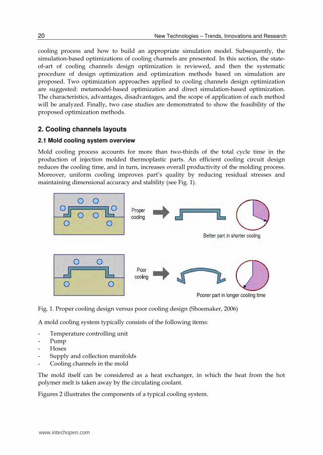
Mold cooling process accounts for more than two-thirds of the total cycle time in the
production of injection molded thermoplastic parts. An efficient cooling circuit design
reduces the cooling time, and in turn, increases overall productivity of the molding process.
Moreover, uniform cooling improves part’s quality by reducing residual stresses and
maintaining dimensional accuracy and stability (see Fig. 1).
Fig. 1. Proper cooling design versus poor cooling design (Shoemaker, 2006)
A mold cooling system typically consists of the following items:
- Temperature controlling unit - Pump - Hoses - Supply and collection manifolds - Cooling channels in the mold
The mold itself can be considered as a heat exchanger, in which the heat from the hot polymer melt is taken away by the circulating coolant.
Figures 2 illustrates the components of a typical cooling system.
Poorer part in longer cooling time
www.intechopen.com

Design and Simulation-Based Optimization of Cooling Channels for Plastic Injection Mold
21
Fig. 2. A typical cooling system in injection molding
2.2 Conventional straight-drilled cooling channels
The common types of straight-drilled cooling channels are parallel and series.
2.2.1 Parallel cooling channels
Parallel cooling channels are drilled straight channels that the coolant flows from a supply manifold to a collection manifold as shown in Fig. 3c. Due to the flow characteristics of the parallel cooling channels, the flow rate along various cooling channels may be different, depending on the flow resistance of each individual cooling channel. This varying of the flow rate, in turn, causes the heat transfer efficiency of the cooling channels to vary from one to another. As a result, cooling of the mold may not be uniform with a parallel cooling-channel configuration.
2.2.2 Serial cooling channels
Cooling channels that are connected in a single loop from the coolant inlet to its outlet are
called serial cooling channels (see Fig. 3b). This type of cooling channel network is the most
commonly used in practice. By design, if the cooling channels are uniform in size, the
coolant can maintain its turbulent flow rate through its entire length. Turbulent flow enables
the heat to be transferred more effectively. For large molds, more than one serial cooling
channel may be required to assure a uniform coolant temperature and thus uniform mold
cooling.
Temperature control
Supply manifold
Collection manifold
Pump
Normal cooling channels Baffles
www.intechopen.com

New Technologies – Trends, Innovations and Research
22
Fig. 3. Conventional straight cooling channels
2.3 Conformal cooling channels
To obtain a uniform cooling, the cooling channels should conform to the surface of the mold
cavity that is called conformal cooling channels. The implementation of this new kind of
cooling channels for the plastic parts with curved surfaces or free-form surfaces is based on
the development of solid free-form fabrication (SFF) technology. On the other hand,
conformal cooing channels can also be made by U-shape milled groove using CNC milling
machine (Sun et al., 2004).
Fig. 4. A layout of conformal cooling channels
The conformal cooling channels are different from straight-drilled conventional cooling
channels. In conventional cooling channels, the free-form surface of mold cavity is
surrounded by straight cooling lines machined by drilling method. It is clear that the
distance from the cooling lines and mold cavity surface varies and results in uneven cooling
in molded part. On the contrary, for the conformal cooling channels, the cooling paths
match the mold cavity surface well by keeping a nearly constant distance between cooling
paths and mold cavity surface (see Fig. 4). It was reported that this kind of cooling channels
gives better even temperature distribution in the molded part than the conventional one.
(b) Straight series cooling channels
(c) Straight parallel cooling channels (a) Straight-drilled cooling channels
www.intechopen.com

Design and Simulation-Based Optimization of Cooling Channels for Plastic Injection Mold
23
Figure 5 shows an example of molds with conformal cooling channels made by direct metal laser sintering method. It was said that this cooling channels not only ensure the high quality of the product but also increase the productivity by 20 %.
Fig. 5. Molds with conformal cooling channels made by laser sintering (Mayer, 2009)
3. Physical and mathematical modeling of cooling channels
In the physical sense, cooling process in injection molding is a complex heat transfer problem. To simplify the mathematical model, some of the assumptions are applied (Park & Kwon, 1998; Lin, 2002). The objective of mold cooling analysis is to find the temperature distribution in the molded part and mold cavity surface during cooling stage. When the molding process reaches the steady-state after several cycles, the average temperature of the mold is constant even though the true temperature fluctuates periodically during the molding process because of the cyclic interaction between the hot plastic and the cold mold. For the convenience and efficiency in computation, cycle-averaged temperature approach is used for mold region and transition analysis is applied to the molded part (Park & Kwon, 1998; Lin, 2002; Rännar, 2008).
The general heat conduction involving transition heat transfer problem is governed by the partial differential equation. The cycle-averaged temperature distribution can be represented by the steady-state Laplace heat conduction equation. The coupling of cycle-averaged and one-dimensional transient approach was applied since it is computationally efficient and sufficiently accurate for mold design purpose (Qiao, 2006; Kennedy, 2008). Heat transfer in the mold is treated as cycle-averaged steady state, and 3D FEM simulation was used for analyzing the temperature distribution. The cycle-averaged approach is applied because after a certain transient period from the beginning of the molding operation, the steady-state cyclic heat transfer within the mold is achieved. The fluctuating component of the mold temperature is small compared to the cycle-averaged component so that cycle-averaged temperature approach is computationally more efficient than periodic transition analysis (Zhou & Li, 2005). Heat transfer in polymer (molding) is considered as transient process. The temperature distribution in the molding is modeled by following equation:
2
2
T T
t zα
∂ ∂=
∂ ∂ (1)
The partial difference equation (1) can be solved conveniently by finite difference method. Due to the nature of thermal contact resistance between polymer and mold, a convective boundary condition (Kazmer, 2007) was applied instead of isothermal boundary condition.
www.intechopen.com
New Technologies – Trends, Innovations and Research
24
This boundary condition expresses the nature of the heat transfer in mold-polymer interface better than isothermal boundary condition.
c ps m p
Th T T k
z
∂ − = − ∂ (2)
where Tps and Tm are molded part surface temperature and mold temperature, respectively; kp is the thermal conductivity of polymer.
The inversion of the heat transfer coefficient hc is called thermal contact resistance (TCR). It is reported that the TCR between the polymer and the mold is not negligible. TCR is the function of a gap, roughness of contact surface, time, and process parameters. The values of TCR are very different (Yu et al., 1990; C-MOLD, 1997; Delaunay et al., 2000; Sridhar & Narh, 2000; Le Goff et al., 2005; Dawson et al., 2008; Hioe et al., 2008; Smith et al., 2008), and they are often obtained by experiment.
The heat flux across the mold-polymer interface is expressed as follows.
p
Tq k
n
∂= −
∂ (3)
where n is the normal vector of the surface.
The cycle-averaged heat flux is calculated by the equation:
0
1ct
c
q qdtt
= (4)
The required cooling time tc is calculated as follows (Menges et al., 2001; Rao & Schumacher, 2004).
2 4
ln i mc
e m
T Tst
T Tπα π
−=
− (5)
where m
p
k
cα
ρ= is the thermal diffusivity of polymer
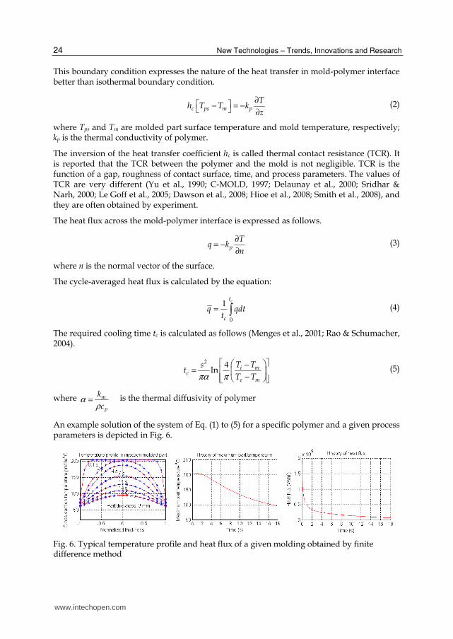
An example solution of the system of Eq. (1) to (5) for a specific polymer and a given process parameters is depicted in Fig. 6.
Fig. 6. Typical temperature profile and heat flux of a given molding obtained by finite difference method
www.intechopen.com

Design and Simulation-Based Optimization of Cooling Channels for Plastic Injection Mold
25
When the heat balance is established, the heat flux supplied to the mold and the heat flux removed from the mold must be in equilibrium. Figure 7 shows the sketch of configuration of cooling system and heat flows in an injection mold. The heat balance is expressed by equation.
0Q Q Qm c e+ + = (6)
where mQ , cQ and eQ are the heat flux from the melt, the heat flux exchange with coolant
and environment respectively.
Fig. 7. Physical modeling of the heat flow and the sketch of cooling system
The heat from the molten polymer is taken away by the coolant moving through the cooling channels and by the environment around the mold’s exterior surfaces. The heat exchanges with the coolant is taken place by force convection, and the heat exchanges with environment is transported by convection and radiation at side faces of the mold and heat conduction into machine platens. In application, the mold exterior faces can be treated as adiabatic because the heat lost through these faces is less than 5% (Park & Kwon, 1998; Zhou & Li, 2005). Therefore, the heat exchange can be considered as solely the heat exchange between the hot polymer and the coolant. The equation of energy balance is simplified by neglecting the heat loss to the surrounding environment.
0mQ Qc+ = (7)
Heat flux from the molten plastic into the coolant can be calculated as (Rao et al., 2002)
3102
[ ( ) ]M E
sQ c T T i xm p m ρ−= − + (8)
Heat flux from the mold that changes with coolant in the time tc amounts to (Park & Kwon, 1998):
( )1
13 1 1
10310
W CQ t T Tc c k Sed stαπ
−−
− = −
− (9)
In fact, the total time that the heat flux transfers to coolant should be cycle time including
filling time tf, cooling time tc and mold opening time t0. By comparing the analysis results
www.intechopen.com

New Technologies – Trends, Innovations and Research
26
obtained by the analytical method using the formula (9) and the analysis result obtained by commercial flow simulation software, the formula (9) under-estimates the heat flux value. On the contrary, if, tc in (9) is replaced by the sum of tf, tc and to, the formula (9) over-estimates the
heat flux from the mold exchanges with coolant. The reason is that the mold temperature at the beginning of filling stage and mold opening stage is lower than others within a molding cycle. The under-estimation or over-estimation is considerable when the filing time and mold opening time is not a small portion compared to the cooling time, especially for the large part
with small thickness (Park & Dang, 2010). For this reason, the formula (9) is adjusted approximately based on the investigation of the mold wall temperature of rectangular flat parts by using both practical analytical model and numerical simulation.
( )1
11 13
2 3
1 110
310f c W Ct toQ t T Tc k Sed stαπ
−− − + +
= −−
(10)
The influence of the cooling channels position on the heat conduction can be taken into
account by applying shape factor Se (Holman, 2002)
2
2 2sinh( / )ln
Se x y x
d
ππ
π
= (11)
Heat transfer coefficient of water is calculated by (Rao & Schumacher, 2004):
0 831 395 ..Red
α = (12)
where the Reynolds number
dR ue ν
= (13)
The cooling time of a molded part in the form of plate is calculated as (Menges et al., 2001;
Rao & Schumacher, 2004):
2
2
4ln M W
E W
s T Ttc
a T Tπ π
−
=−
(14)
From the formula (14), it can be seen that the cooling time only depends on the thermal
properties of a plastic, part thickness, and process conditions. It does not directly depend on
cooling channels configuration. However, cooling channels’ configuration influences the
mold wall temperature WT , so it indirectly influences the cooling time.
By combining equations from (7) to (14), one can derive the following equation:
2 2 21 1 4 1 120 8 22 2 30 03139
sinh( )[ ( ) ]ln ln
..
M EM W
W C E W
ysxc T T i xp m T Tsx t tofT T k d T TR ast e
πρ
π π ππ π
− + −
+ = + + − −
(15)
www.intechopen.com
Design and Simulation-Based Optimization of Cooling Channels for Plastic Injection Mold
27
Mathematically, with preset TM, TE, WT , predefined tf and to, and others thermal properties
of material, equation (15) presents the relation between cooling time tc and the variables
related to cooling channels configuration including pitch x, depth y and diameter d. In
reality, the mold wall temperature WT is established by the cooling channels configuration
and predefined parameters TM, TE, tf, to, and thermal properties of material in equation (15).
The value of WT , in turn, results in the cooling time calculated by the formula (14).
4. Simulation-based optimization of cooling channels
4.1 Cooling system design and optimization: The state-of-the-art
For many years, the importance of cooling stage in injection molding has drawn a great
attention from researchers and mold designers. They have been struggling for the
improvement of the cooling system in the plastic injection mold. This field of study can be
divided into two groups:
• Optimizing conventional cooling channels (straight-drilled cooling lines).
• Finding new architecture for injection mold cooling channels (conformal cooling channels).
The first group focuses on how to optimize the configuration of the cooling system in terms of shape, size, and location of cooling lines (Tang et al., 1997; Park & Kwon, 1998; Lin, 2002; Rao et al., 2002; Lam et al., 2004; Qiao, 2005; Li et al., 2009; Zhou et al., 2009; Hassan et al., 2010). These studies used some of methods from semi-analytical method to finite difference, boundary element method (BEM), and finite element method (FEM). Rao N. (Rao et al., 2002) proposed the optimization of cooling systems in injection mold by using an applicable analytical model based on 2D heat transfer equations. Most studies mainly focus on the numerical methods. Park and Kwon (Park & Kwon, 1998) proposed the optimization method for cooling system design in injection molding process by applying design sensitive method. The heat transfer was treated as 2D problem. Boundary element method is preferred to solve the heat transfer problem in mold cooling design (Qiao, 2005; Zhou et al., 2009). BEM is effective for calculating heat transfer in the mold because: (a) the discretization associated with BEM does not extend to the interior region of the mold that there is no need for mesh generation when the cooling channels are rearranged, (b) BEM method reduces the input data due to the reduction of total nodes so that the computation cost is reduced in comparison to finite element method. Although the BEM can extend to 3D application as the new feature of most of commercial injection molding software, these works are mainly based on 2D case studies that are not always practical. Moreover, most of case studies are simple.
For 3D analysis in heat transfer in injection mold, 3D simulation based on professional or commercial software is the common approach. Nowadays, commercial simulation software
can help the designer to calculate the temperature distribution and cooling time. Nevertheless, it is only the simulation tools, and these tools themselves are often confined in a single simulation. The optimization task needs a scientific strategy and methodology to obtain a believable result. Lam Y. C. et al. (Lam et al., 2004) proposed an evolutionary
approach for cooling system optimization in plastic injection molding. In their study, the direct integration between GA algorithm in optimization and CAE software (Moldflow, a software package that uses BEM for mold cooling analysis) is employed. This is the best
www.intechopen.com

New Technologies – Trends, Innovations and Research
28
choice, nowadays, for cooling optimization for the injection mold. However, there are some limitations about the simulation time or computing cost because GA requires a lot of function evaluation before reaching convergence. If the molded part is complex or it has
great number of element, the computing cost is extremely high. The optimization strategy also has some limits, and it is mentioned and discussed later.
The second group investigates the way to build the cooling layout namely conformal cooling channels that conform to the mold cavity surface and examines the effectiveness of
this cooling system. Solid free-from fabrication (SFF) or rapid prototype (RP) techniques have been applied to build this complex cooling system. It was reported that cooling quality is better than that of conventional cooling channels (Sachs et al., 2000; Xu et al., 2001; Ferreira & Mateus, 2003; Dimla et al., 2005; Au & Yu, 2007; Gloinn et al., 2007; Rännar et al.,
2007; Park & Pham, 2009; Safullah et al., 2009). Prototyping technologies with metal powder that can make the mold with conformal cooling channels include selective laser sintering (SLS), 3D printing (3DP), electron beam melting, and laser engineered net shaping.
Classifying optimization technique by searching direction, there are two different algorithms: gradient-based and non-gradient-based optimization techniques. The advantages and disadvantages of these algorithms are straightforward in the literature. Gradient-based methods face difficulty when number of variables increase, and they get risk
of local extremum. On the contrary, GA algorithms tend to reach global optimum, but the huge number of function evaluations or the number of simulations is required. If the simulation cost of each simulation is high, GA tool is extremely expensive.
When the molded part or the cooling channels is complex, the analytical cooling design formulas based on 1D or 2D analysis become inaccurate. The strength of general CAE tool such as ANSYS and COSMOS, or professional CAE tools for injection molding simulation such as Moldflow, Moldex3D, and Timon-3D have been exploited successfully in many recent
publications. ANSYS and COSMOS are based on FEM method for heat transfer analysis. Moldflow uses the BEM method for the 3D mold cooling problem due to the need to mesh only the outer surface of the mold. Moldex3D applies finite volume method. This CAE tool
uses a variety of element shapes for analysis, and it is possible to create fine wedge element mesh near the mold surface and coarse tetrahedral mesh in the center to reduce the number of elements and improve the heat transfer calculation near the mold wall (Kennedy, 2008).
As previously mentioned, using commercial CAE software for cooling simulation is the main tendency of recent practical studies when the molded parts or cooling channels are complex. Sun I. F. et al. (Sun et al., 2002) proposed U-shape conformal milled groove cooling channels for injection molds. Simulation was done to compare the cooling effect of this kind of channels with straight cooling channels by using COSMOS, an analysis software based on FEM method. Of course, conformal cooling channels offer a better cooling effect than those of straight cooling channels. Similarly, some of other studies investigated the cooling effect of conformal cooling channels made by rapid prototyping method (Dimla et al., 2005; Au & Yu, 2007; Gloinn et al., 2007; Rännar et al., 2007; Safullah et al., 2009). CAE simulation or experiments show that conformal cooling channels are better than conventional straight cooling channels in terms of heat transfer. The mold temperature distributes more even than that of straight cooling channels. However, most of these studies have not mentioned about the optimization problem of conformal cooling channels.
www.intechopen.com
Design and Simulation-Based Optimization of Cooling Channels for Plastic Injection Mold
29
In fact, mold cooling design not only aim at the uniform cooling but also minimize cooling time to a target mold wall temperature. How far it is from cooling channels to the mold cavity surface and what the best coolant temperature is for complex cooling channels still the considerable problems that have not been resolved thoroughly. It still lacks of study of how well this conformal cooling system performs and how to optimize its configuration in order to obtain the minimum cooling time, even cooling and reasonable mold making cost. In addition, cooling design is often based on designer’s experience and intuition. When molding geometry becomes more complex, experience-based and trial-and-error approaches would be time-consuming and less feasible (Tang et al., 1997; Lin, 2002; Lam et al., 2004; Qiao, 2006).
4.2 Simulation-based optimization approaches
Over the past decade, we have seen a tremendous growth in the use of CAE in mold design and injection molding process analysis. By using CAE software for numerical simulation of the injection molding process, it is possible to predict the quality of molded part and to detect the potential problems at the early design stage. Since a computer simulation is faster and cheaper than building prototype molds or performing real test on injection molding machines, it reduces manufacturing cost and the time-to-market. Design optimization always requires a loop of design-evaluate-redesign. Therefore, the ability to quickly and easily assess the different configuration of the mold and process parameters accelerates the search of variety of process conditions and mold configuration to determine the optimum design. More over, selecting appropriate optimization methodology also reduces the simulation time as well as increases the fidelity of the optimization process.
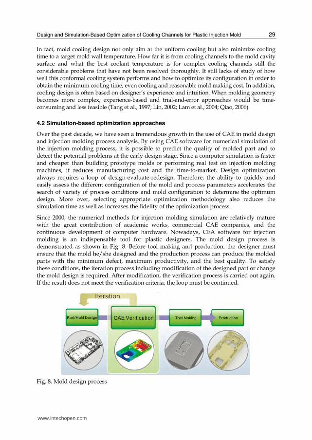
Since 2000, the numerical methods for injection molding simulation are relatively mature with the great contribution of academic works, commercial CAE companies, and the continuous development of computer hardware. Nowadays, CEA software for injection molding is an indispensable tool for plastic designers. The mold design process is demonstrated as shown in Fig. 8. Before tool making and production, the designer must ensure that the mold he/she designed and the production process can produce the molded parts with the minimum defect, maximum productivity, and the best quality. To satisfy these conditions, the iteration process including modification of the designed part or change the mold design is required. After modification, the verification process is carried out again. If the result does not meet the verification criteria, the loop must be continued.
Fig. 8. Mold design process
www.intechopen.com

New Technologies – Trends, Innovations and Research
30
4.3 Optimization methods and systematic procedure for optimization
4.3.1 Direct numerical optimization methods
The terminology “direct numerical optimization methods” means that it is unnecessary to use indirect metamodel (refers to Section 4.3.2). In this case, gradient-based using finite difference method for calculating the derivative or other non-gradient-based algorithms such as GA, simulated annealing, heuristic search is applied directly. The optimization loop is terminated when the convergence is reached (optimum solution is found), or the termination criteria are active. Because the computing cost of CAE simulation is usually expensive, one of the termination criteria is often the pre-defined maximum number of simulations. The systematic procedure of direct simulation-based optimization in injection molding is depicted in Fig. 9.
Fig. 9. Systematic procedure of direct simulation-based optimization in injection molding
Determining objective(s), design variables, design space
Choosing an arbitrary initial design
Running simulation
Evaluating objective(s) functions, constraint(s) and modifying design variables according to a chosen
optimization technique
Convergence or reach the termination criteria?
Obtaining an optimal solution
Fine-tune or refine search (if necessary)
Finish
Start
Yes
No
www.intechopen.com

Design and Simulation-Based Optimization of Cooling Channels for Plastic Injection Mold
31
The number of iterations depends on the initial point and optimization technique, and it may give different optimum design points. Usually, the number of iterations for searching the optimum design point in gradient-based optimization is large. The more the number of design variables, the more the number of iterations. Also, local optimum is some time obtained rather than global optimum. There is no guarantee that the optimal solution or a solution closed to the optimum is found. In case of using non-gradient-based optimization techniques, for example GA, if the number of generations or the number of function evaluations is low, they prone to reach the neighbor of optimum point rather the optimum point. Therefore, the computational cost of direct simulation-based optimization method is extremely high because the each simulation in injection molding may last hours if the number of element is great.
The advantage of direct simulation-based optimization is that the verification at optimum point is unnecessary. It is different from metamodel-based optimization method that will be presented in Section 4.3.2
The framework of CAE simulation and computer-based optimizer integration using direct numerical optimization techniques is proposed as shown in Fig. 10. There are two components in this framework including optimizer controller component and CAE component. The CAE component is responsible for analysis or simulation. Optimizer controller is responsible for reading the output from CAE component, evaluating objective and constraint functions, and modifying inputs (design variables) according to the algorithm of the selected optimization technique. All the processes in the framework are performed automatically by the instruction commands coded by a programming language.
Fig. 10. Framework of CAE simulation and computer-based optimizer integration using direct numerical optimization techniques
CAE injection molding modeler and simulation
Results file: - Mold/part temperature - Mold temperature deviation - Required cooling time - Warpage (deflection) - Residual stress - …..
Input data stored in an input file
Read results file (evaluating function)
Modify design variables according to optimization
techniques (GA or gradient-based techniques)
Scripting language
Optimizer (controller) CAE simulation
Query and extract the necessary output
Scripting language
www.intechopen.com

New Technologies – Trends, Innovations and Research
32
4.3.2 Simulation-based optimization using metamodeling techniques
Metamodeling technique or approximation-based optimization technique is a method that objective functions are frequently approximated to explicit functions in the form of low
order polynomials with an acceptable accuracy. This technique has some benefits such as being easy to connect to simulation program, to render a view of entire design space as well as computational efficiency (Papalambros, 2002; Park, 2007; Wang & Shan, 2007; Park &
Dang, 2010). The systematic procedure of metamodel-based optimization technique applied to injection molding is depicted in Fig. 11. The metamodel types can be RSM, radial basis
Fig. 11. Systematic procedure of metamodel-based optimization in injection molding
Determining objective(s), design variables, design space
Choosing metamodel type
DOE or space sampling
Generating modeling & Running CAE injection molding simulations
Fitting metamodel: RSM, RBF, or ANN
Is the model adequate?
Performing optimization
Evaluating optimum point
Is the accuracy satisfactory?
Finish
Seq
uen
tial
im
pro
vem
ent
or
chan
ge
the
met
amo
del
ty
pe
Start
Yes
No
Yes
No
www.intechopen.com

Design and Simulation-Based Optimization of Cooling Channels for Plastic Injection Mold
33
function, Kriging model, or ANN. The common DOE or space sampling techniques include full factorial, D-optimal design, central composite design, orthogonal array, Latin hypercube, and optimal Latin hypercube. After running a predefined number of simulations (except adaptive metamodel technique) according to the DOE strategy, the approximation process is carried out. The metamodel is then built. The optimization process is performed using mathematical approximation or metamodel. Because the objective and constraint functions are in the form of explicit equation, the computing cost for finding the optimum solution can be ignored compared to the total simulation cost. The theories of metamodel-based optimizations are out of the scope of this book chapter.
Different from direct simulation-based optimization method, the evaluating step needs to be done in order to verify the fidelity of the metamodel at the “optimum” point because it always exist an error between the metamodel and real response. In other words, there is an error between the predicted and actual values at the optimum point because metamodels are approximate models. If the error between the responses obtained by prediction and CAE simulation is acceptable or if it satisfies the designer, the optimization process is finished successfully. Otherwise, the sequential improvement step should be carried out.
Framework of CAE simulation and computer-based optimizer integration based on metamodeling techniques is proposed as shown in Fig. 12. There are two components in this
Fig. 12. Framework of CAE simulation and computer-based optimizer integration based on metamodeling techniques
Outputs (responses): Mold temperature,
cooling time, stress, shrinkage, warpage…
Outputdata storage
Selecting the values of design variables based on DOE
techniques
Meta- model
Integration controller& Metamodeling
processor
CAE injection molding modeling & simulation
Fixed design parameters
and constraints
CAE component Integration controller
Input file
www.intechopen.com
New Technologies – Trends, Innovations and Research
34
framework including integration controller component and CAE component. The CAE component is responsible for reading the inputs data, performing analysis or simulation, and writing outputs to a text file. Integration controller is responsible for DOE (determining the combinations of design parameters) and controlling the synchronization of the integration process. The controller must wait until a simulation finishes and ensure all the outputs data are stored safely before calling the next simulation or iteration. The loop in the framework is terminated when all the number of simulations determined by DOE technique has been done. Metamodel is then built and verified. Subsequently, the optimization process is carried out based on the metamodel.
4.4 Software implementation
Some software that satisfies the functional requirements shown in the framework can be used to implement the integration and optimization processes. These software should have the ability of automation. It means that all the tasks are programmed and performed
automatically without the interaction of the engineering designers while the program is executed. Any CAE software that supports programming and I/O command can be used to implement the proposed framework. In reality, there are not many injection molding software. Moldflow is one of a popular CAE tool for injection molding simulation that offers
the API tool for automating most of the modeling, analyzing, and simulation task.
Selection of implementing software for the framework of integration system depends on the available tools and individual choices of the engineering designers. They can use any
standard programming language such as Visual Basic, Visual C or MATLAB for implementing the connection between the proposed integration controller and CAE component, controlling the integration loop, generating the metamodel and solving the optimization problem. iSight software is also a powerful tool that helps the designer to
integrate the optimizer and injection molding simulation software. It is clear that there are some options for choosing appropriate software from the previously introduced ones that can be used to build the implemented software. In this work, the collection of Matlab and
Moldflow, or the couple of iSight and Moldflow was implemented to make the integration frameworks. The important thing is that an API program must be coded using Visual Basic Scripting language. This API program calls most of the functions of Moldflow to perform the modeling and simulation task.
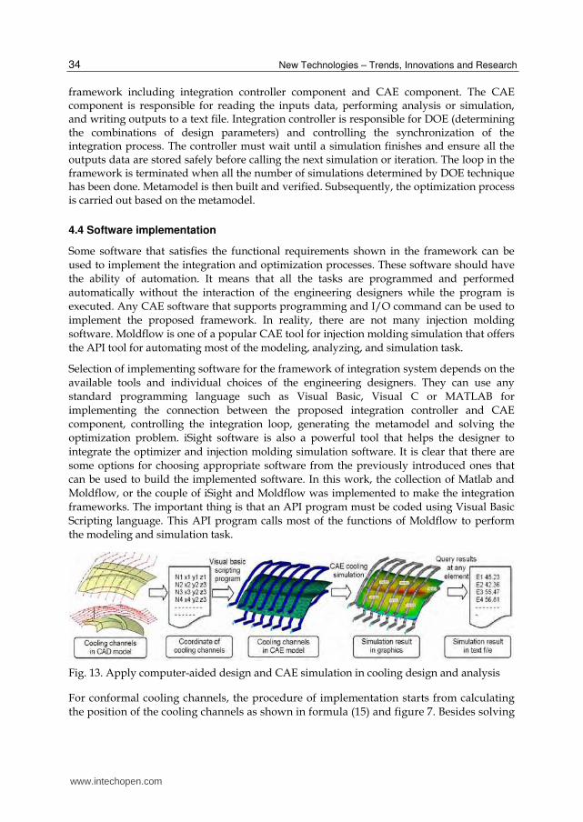
Fig. 13. Apply computer-aided design and CAE simulation in cooling design and analysis
For conformal cooling channels, the procedure of implementation starts from calculating the position of the cooling channels as shown in formula (15) and figure 7. Besides solving
www.intechopen.com

Design and Simulation-Based Optimization of Cooling Channels for Plastic Injection Mold
35
explicit equation for finding the good initial cooling channels configuration, CAD modeling and CAE simulation and analysis are the important tools to support design process, fine-tune and verify the result. The systematic procedure of applying computer-
aided design and CAE simulation for cooling channels design optimization can be presented as follows (see Fig. 13). First of all, based on the results obtained from the analytical analysis step, approximate cooling channels are modeled by projecting cooling channels layout from a plane to the offset surfaces of the molded part. Subsequently, the
coordinate of cooling channels are generated and stored in a text file. Next, the conformal cooling channels are imported to CAE environment and meshed automatically by an Application Programming Interface (API) via Visual Basis Scripting (VBS) language. After that, cooling simulation is performed to obtain the exact results of average mold
temperature and temperature distribution of the molded part. Finally, the temperature of all elements or considered elements are queried and stored in a text file to support data for optimization process. The third step to the last step are looped until the optimal
conditions are satisfied. This process can be controlled automatically by an optimizer programmed by Matlab and VBS language.
5. Case studies
5.1 Case study 1: Optimization of conventional straight cooling channels
Based on the two proposed algorithms and the two frameworks presented in Section 4, there
are two ways for implementing the optimization method for designing optimum straight
cooling channels. As previously mentioned, there is no theoretical method to prove that a
specific optimization technique is better than the others in all circumstance. The existence of
many optimization methods is the evidence for this conclusion. The way for implementing
the optimization method for designing optimum cooling system is illustrated by considering
a typical design example as shown in Figure 14. The molded part is a box made by PP
material with dimension 400×250×150 mm and 2.5 mm thickness.
Fig. 14. A plastic box used as a typical example for cooling design optimization
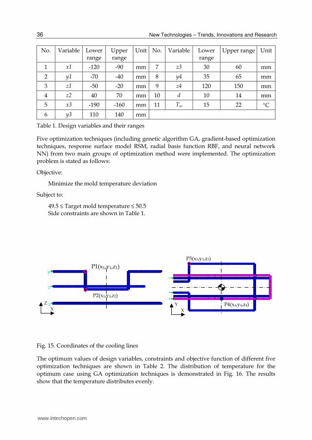
The cooling channels configuration is shown in Fig. 14. The positions of cooling lines are
determined by the coordinates of points P1 to P4 due to the symmetric characteristic of the
cooling channels (see Fig. 15). Mold material is P20 steel. All the material properties of PP
plastic and P20 steel are obtained from the material database of Moldflow software. Because
of the symmetry, there are 11 design variables as shown in Table 1.
www.intechopen.com
New Technologies – Trends, Innovations and Research
36
No. Variable Lower range
Upper range
Unit No. Variable Lower range
Upper range Unit
1 x1 -120 -90 mm 7 z3 30 60 mm
2 y1 -70 -40 mm 8 y4 35 65 mm
3 z1 -50 -20 mm 9 z4 120 150 mm
4 z2 40 70 mm 10 d 10 14 mm
5 x3 -190 -160 mm 11 Tw 15 22 °C
6 y3 110 140 mm
Table 1. Design variables and their ranges
Five optimization techniques (including genetic algorithm GA, gradient-based optimization
techniques, response surface model RSM, radial basis function RBF, and neural network
NN) from two main groups of optimization method were implemented. The optimization
problem is stated as follows:
Objective:
Minimize the mold temperature deviation
Subject to:
49.5 ≤ Target mold temperature ≤ 50.5 Side constraints are shown in Table 1.
Fig. 15. Coordinates of the cooling lines
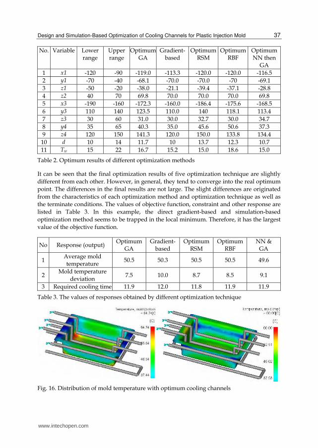
The optimum values of design variables, constraints and objective function of different five
optimization techniques are shown in Table 2. The distribution of temperature for the
optimum case using GA optimization techniques is demonstrated in Fig. 16. The results
show that the temperature distributes evenly.
X
YX
Z
P1(x1,y1,z1)
P2(x2,y2,z2)
P3(x3,y3,z3)
P4(x4,y4,z4)
www.intechopen.com
Design and Simulation-Based Optimization of Cooling Channels for Plastic Injection Mold
37
No. Variable Lower range
Upper range
Optimum GA
Gradient-based
Optimum RSM
Optimum RBF
Optimum NN then
GA
1 x1 -120 -90 -119.0 -113.3 -120.0 -120.0 -116.5
2 y1 -70 -40 -68.1 -70.0 -70.0 -70 -69.1
3 z1 -50 -20 -38.0 -21.1 -39.4 -37.1 -28.8
4 z2 40 70 69.8 70.0 70.0 70.0 69.8
5 x3 -190 -160 -172.3 -160.0 -186.4 -175.6 -168.5
6 y3 110 140 123.5 110.0 140 118.1 113.4
7 z3 30 60 31.0 30.0 32.7 30.0 34.7
8 y4 35 65 40.3 35.0 45.6 50.6 37.3
9 z4 120 150 141.3 120.0 150.0 133.8 134.4
10 d 10 14 11.7 10 13.7 12.3 10.7
11 Tw 15 22 16.7 15.2 15.0 18.6 15.0
Table 2. Optimum results of different optimization methods
It can be seen that the final optimization results of five optimization technique are slightly
different from each other. However, in general, they tend to converge into the real optimum
point. The differences in the final results are not large. The slight differences are originated
from the characteristics of each optimization method and optimization technique as well as
the terminate conditions. The values of objective function, constraint and other response are
listed in Table 3. In this example, the direct gradient-based and simulation-based
optimization method seems to be trapped in the local minimum. Therefore, it has the largest
value of the objective function.
No Response (output) Optimum
GA Gradient-
based Optimum
RSM Optimum
RBF NN &
GA
1 Average mold temperature
50.5 50.3 50.5 50.5 49.6
2 Mold temperature
deviation 7.5 10.0 8.7 8.5 9.1
3 Required cooling time 11.9 12.0 11.8 11.9 11.9
Table 3. The values of responses obtained by different optimization technique
Fig. 16. Distribution of mold temperature with optimum cooling channels
www.intechopen.com
New Technologies – Trends, Innovations and Research
38
5.2 Case study 2: Optimization of conformal cooling channels
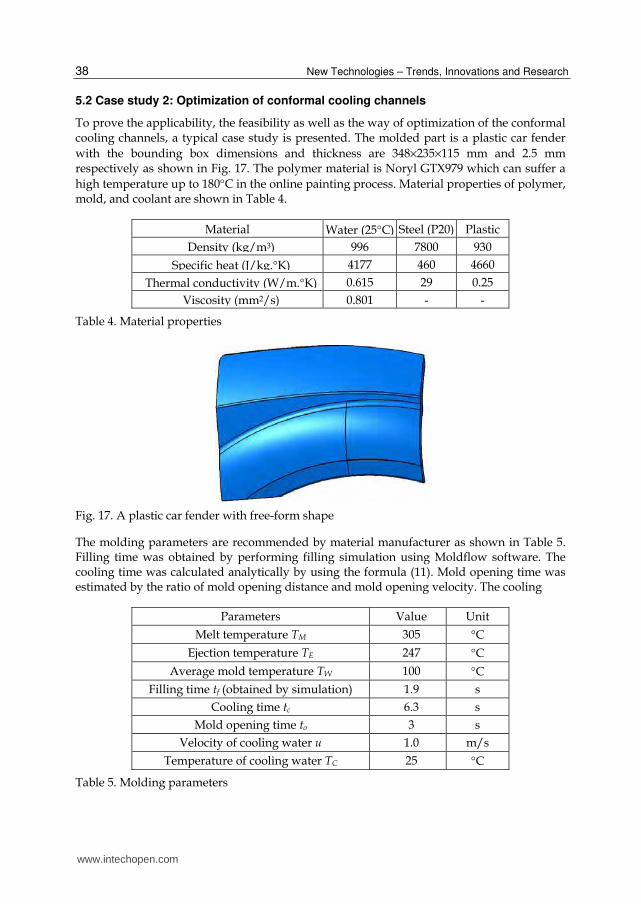
To prove the applicability, the feasibility as well as the way of optimization of the conformal cooling channels, a typical case study is presented. The molded part is a plastic car fender
with the bounding box dimensions and thickness are 348×235×115 mm and 2.5 mm respectively as shown in Fig. 17. The polymer material is Noryl GTX979 which can suffer a
high temperature up to 180°C in the online painting process. Material properties of polymer, mold, and coolant are shown in Table 4.
Material Water (25°C) Steel (P20) Plastic
Density (kg/m3) 996 7800 930
Specific heat (J/kg.°K) 4177 460 4660
Thermal conductivity (W/m.°K) 0.615 29 0.25
Viscosity (mm2/s) 0.801 - -
Table 4. Material properties
Fig. 17. A plastic car fender with free-form shape
The molding parameters are recommended by material manufacturer as shown in Table 5. Filling time was obtained by performing filling simulation using Moldflow software. The cooling time was calculated analytically by using the formula (11). Mold opening time was estimated by the ratio of mold opening distance and mold opening velocity. The cooling
Parameters Value Unit
Melt temperature TM 305 °C
Ejection temperature TE 247 °C
Average mold temperature TW 100 °C
Filling time tf (obtained by simulation) 1.9 s
Cooling time tc 6.3 s
Mold opening time to 3 s
Velocity of cooling water u 1.0 m/s
Temperature of cooling water TC 25 °C
Table 5. Molding parameters
www.intechopen.com

Design and Simulation-Based Optimization of Cooling Channels for Plastic Injection Mold
39
channels are machined by milling machine. According to the required length of milling tool
to machine the cooling groove, the cooling channel diameter was selected as 12 mm. The
range of pitch x was selected from 4d to 5d due to a high level of ejection temperature and
requirement of reducing the number of cooling paths. By applying the solver tools, the
results of analytical method are shown in Table 6.
Parameters Value Unit
Cooling channel diameter d 12 mm
Cooling channels pitch x 57.7 mm
Cooling channels depth y 45.2 mm
Velocity of cooling water u 1.0 m/s
Reynolds number Re 11952
Total flow rate of coolant 40.7 l/min
Heat transfer coefficient α 4667 W/m2.°K
Table 6. The results of optimization obtained from analytical method
The results obtained by analytical method (equation 15) were used to deploy the conformal
cooling channels as an initial design. Subsequently, Moldflow software was used to perform
the cooling analysis. The simulation results for the first run showed that the average mold
cavity surface temperature was 98.6°C. This value nearly approaches the target mold
temperature ( WT = 100°C). To approach the target mold temperature, the pitch x of cooling
channels was fixed and the depth y of both core side and cavity side were adjusted. Linear
interpolation method was used as a strategy to reduce the number of iteration of simulation.
Fig. 18. Average temperature distribution of the part
The final results were obtained rapidly after performing three more simulations. The
average mold temperature is 100.4°C. The maximum temperature at the middle layer of the
part is 221.2°C at the end of cooling time, so it can allow ejecting the molded part safely without distortion. The temperature on the part distributes quite uniform even though the free-form shape of the part is complex (see Fig. 18). The simulation result shows that the time to freeze the part to ejection temperature is 6.1 second. This result agrees well with the
cooling time calculated by formula (11) (6.3 second). This means that the cooling design
www.intechopen.com

New Technologies – Trends, Innovations and Research
40
results satisfy the optimality conditions. The optimum values of the distances from the cooling channels to the part surface are 46.0 mm and 46.9 mm for the core side and cavity side of the mold, respectively.
We compared the cooling effect of an un-optimized design and the optimized design and found that the range between maximum and minimum temperature in case optimized conformal cooling channel is always smaller than those of the un-optimized one (see Fig. 19 as an example). In addition, the comparison of the warpage between the best straight cooling channel and the conformal one was also carried out. The simulation result shows that conformal cooling channel reduces 15.7% warpage for this case study (see Fig. 20). The effect of conformal cooling channel varies according to the complexness of the molded part. In general, conformal cooling channels always offer a better uniform cooling and a lower warpage than straight cooling channels. These are the advantages of conformal cooling channels.
Fig. 19. Comparison of temperature profile between un-optimized and optimized conformal cooling channels
Fig. 20. Comparison of warpage between conventional straight cooling channel and conformal cooling channel
- Minimum temperature: 66.5°C
- Maximum temperature: 138.2°C
- Average temperature: 106.9°C - Standard deviation: 14.47
(a) An un-optimized design:
- Minimum temperature: 70.5°C
- Maximum temperature: 132.8°C
- Average temperature: 107.0°C - Standard deviation: 13.81
(b) Optimized design:
www.intechopen.com

Design and Simulation-Based Optimization of Cooling Channels for Plastic Injection Mold
41
6. Conclusion
In summary, the foundation of heat transfer process happening in the plastic injection mold
was systematically present in this book chapter. Physical and mathematical modelings of the cooling channels are introduced. It supports the reader the basic governing equations related to the cooling process and how to build an appropriate simulation model. Subsequently, the simulation-based optimizations of cooling channels are presented. The
state-of-the-art of cooling channels design optimization was also reviewed. Then, the systematic procedure of design optimization and optimization methods based on simulation were proposed. Two optimization approaches applied to cooling channels design
optimization were suggested: metamodel-based optimization and direct simulation-based optimization. The characteristics, advantages, disadvantages, and scope of application of each method were analyzed. Two case studies on conventional straight-drilled and conformal cooling channels are demonstrated to show the feasibility of the proposed
optimization methods.
Cooling design optimization of injection molding for a complex free-form molded part requires a complicated analysis steps, optimization strategy, and appropriate computer aided tools. This book chapter presents a systematic method for optimizing the cooling channels in order to obtain the target mold temperature and reduce the cooling time and the non-uniformity of temperature distribution of the molded part. To increase the computational effectiveness, both analytical method and simulation-based method were used successively.
When the fidelity of the optimization result is considered, the support of CAE tools, API programming language, and the combination optimization techniques are important to increase the preciseness of the analysis results and to reduce the simulation cost. The
proposed methods have been tested in various practical cases in which the plastic car fender and plastic box are the typical case studies. The results obtained from the case studies point out that the proposed methods of cooling channels optimization can be used successfully with less time-consuming and less effort of designers to improve the part quality and the
productivity of plastic production.
7. Acknowledgment
This work was supported by Research Fund of the University of Ulsan, Korea (2011)
8. References
Au, K. & Yu, K. (2007). A scaffolding architecture for conformal cooling design in rapid plastic injection moulding. The International Journal of Advanced Manufacturing Technology 34(5), pp. 496-515.
C-MOLD (1997). User's manual. New York, AC Technology. Chen, X.; Lam, Y. C. & Li, D. Q. (2000). Analysis of thermal residual stress in plastic injection
molding. Journal of Materials Processing Technology 101(1-3), pp. 275-280. Dawson, A.; Rides, M.; Allen, C. R. G. & Urquhart, J. M. (2008). Polymer-mould interface
heat transfer coefficient measurements for polymer processing. Polymer Testing 27(5), pp. 555-565.
www.intechopen.com

New Technologies – Trends, Innovations and Research
42
Delaunay, D.; Bot, P. L.; Fulchiron, R.; Luye, J. F. & Regnier, G. (2000). Nature of contact between polymer and mold in injection molding. Part I: Influence of a non-perfect thermal contact. Polymer Engineering & Science 40(7), pp. 1682-1691.
Dimla, D. E.; Camilotto, M. & Miani, F. (2005). Design and optimisation of conformal cooling channels in injection moulding tools. Journal of Materials Processing Technology 164-165, pp. 1294-1300.
Ferreira, J. C. & Mateus, A. (2003). Studies of rapid soft tooling with conformal cooling channels for plastic injection moulding. Journal of Materials Processing Technology 142(2), pp. 508-516.
Gloinn, T. O.; Hayes, C.; Hanniffy, P. & Vaugh, K. (2007). FEA simulation of conformal cooling within injection moulds. International Journal of Manufacturing Research 2007 2(2), pp. 162-170.
Gloinn, T. O.; Hayes, C.; Hanniffy, P. & Vaugh, K. (2007). FEA simulation of conformal cooling within injection moulds. International Journal of Manufacturing Research 2007 2(2), pp. 162 - 170
Hassan, H.; Regnier, N.; Le Bot, C. & Defaye, G. (2010). 3D study of cooling system effect on the heat transfer during polymer injection molding. International Journal of Thermal Sciences 49(1), pp. 161-169.
Hioe, Y.; Chang, K.-C.; Zuyev, K.; Bhagavatula, N. & Castro, J. M. (2008). A simplified approach to predict part temperature and minimum ldquosaferdquo cycle time. Polymer Engineering & Science 48(9), pp. 1737-1746.
Holman, J. P. (2002). Heat transfer, McGraw-Book Company. Kazmer, D. O. (2007). Injection mold design engineering. Munich, Carl Hanser Verlag. Kennedy, P. K. (2008). Practical and scientific Aspects of injection molding simulation.
Materials Technology, Eindhoven University of Technology. Doctoral. Lam, Y. C.; Zhai, L. Y.; Tai, K. & Fok, S. C. (2004). An evolutionary approach for cooling
system optimization in plastic injection moulding. International Journal of Production Research 42(10), pp. 2047 - 2061.
Le Goff, R.; Poutot, G.; Delaunay, D.; Fulchiron, R. & Koscher, E. (2005). Study and modeling of heat transfer during the solidification of semi-crystalline polymers. International Journal of Heat and Mass Transfer 48(25-26), pp. 5417-5430.
Li, X.-P.; Zhao, G.-Q.; Guan, Y.-J. & Ma, M.-X. (2009). Optimal design of heating channels for rapid heating cycle injection mold based on response surface and genetic algorithm. Materials & Design 30(10), pp. 4317-4323.
Lin, J. C. (2002). Optimum cooling system design of a free-form injection mold using an abductive network. Journal of Materials Processing Technology 120(1-3), pp. 226-236.
Mayer, S. (2009). Optimised mould temperature control procedure using DMLS. Whitepaper, EOS GmbH Electro Optical Systems, Robert-Stirling-Ring 1, D-82152 Krailling/Munich, www.eos.info.
Menges, G.; Michaeli, W. & Mohren, P. (2001). How to make injection molds. Munich, Hanser Publishers.
Papalambros, P. Y. (2002). The optimization paradigm in engineering design: promises and challenges. Computer-Aided Design 34, pp. 939-951.
Park, G.-J. (2007). Analytic methods for design practice. London, Springer. Park, H. & Pham, N. (2009). Design of conformal cooling channels for an automotive part.
International Journal of Automotive Technology 10(1), pp. 87-93.
www.intechopen.com

Design and Simulation-Based Optimization of Cooling Channels for Plastic Injection Mold
43
Park, H. S. & Dang, X.-P. (2010). Structural optimization based on CAD-CAE integration and metamodeling techniques. Computer-Aided Design 42 (10), pp. 889-902.
Park, H. S. & Dang, X. P. (2010). Optimization of conformal cooling channels with array of baffles for plastic injection mold. International Journal of Precision Engineering and Manufacturing 11(6), pp. 1-12.
Park, S. J. & Kwon, T. H. (1998). Optimal cooling system design for the injection molding process. Polymer Engineering & Science 38(9), pp. 1450-1462.
Qiao, H. (2005). Transient mold cooling analysis using BEM with the time-dependent fundamental solution. International Communications in Heat and Mass Transfer 32(3-4), pp. 315-322.
Qiao, H. (2006). A systematic computer-aided approach to cooling system optimal design in plastic injection molding. International Journal of Mechanical Sciences 48(4), pp. 430-439.
Rännar, L.-E. (2008). On Optimization of Injection Molding Cooling. Department of Engineering Design and Materials. Trondheim, Norwegian University of Science and Technology. Ph.D.
Rännar, L. E.; Glad, A. & Gustafson, C. G. (2007). Efficient cooling with tool inserts manufactured by electron beam melting. Rapid Prototyping Journal 13(3), pp. 128-135.
Rao, N. S. & Schumacher, G. (2004). Design formulas for plastics engineers. Munich, Hanser Verlag.
Rao, N. S.; Schumacher, G.; Schott, N. R. & O'brien, K. T. (2002). Optimization of Cooling Systems in Injection Molds by an Easily Applicable Analytical Model. Journal of Reinforced Plastics and Composites 21(5), pp. 451-459.
Sachs, E.; Wylonis, E.; Allen, S.; Cima, M. & Guo, H. (2000). Production of injection molding tooling with conformal cooling channels using the three dimensional printing process. Polymer Engineering & Science 40(5), pp. 1232-1247.
Safullah, A. B. M.; Masood, S. H. & Sbarski, I. (2009). Cycle time optimization and part quality improvement using novel cooling channels in plastic injection moulding, Society of Plastics Engineers.
Shoemaker, J. (2006). Moldflow design guide: a resource for plastic engineers. Munchen, Hanser Verlage.
Smith, A. G.; Wrobel, L. C.; McCalla, B. A.; Allan, P. S. & Hornsby, P. R. (2008). A computational model for the cooling phase of injection moulding. Journal of Materials Processing Technology 195(1-3), pp. 305-313.
Sridhar, L. & Narh, K. A. (2000). Finite size gap effects on the modeling of thermal contact conductance at polymer-mold wall interface in injection molding. Journal of Applied Polymer Science 75(14), pp. 1776-1782.
Sun, Y.; Lee, K. & Nee, A. (2002). The application of U-shape milled grooves for cooling of injection moulds. Proceedings of the Institution of Mechanical Engineers, Part B: Journal of Engineering Manufacture 216(12), pp. 1561-1573.
Sun, Y. F.; Lee, K. S. & Nee, A. Y. C. (2004). Design and FEM analysis of the milled groove insert method for cooling of plastic injection moulds. The International Journal of Advanced Manufacturing Technology 24(9), pp. 715-726.
Tang, L. Q.; Chassapis, C. & Manoochehri, S. (1997). Optimal cooling system design for multi-cavity injection molding. Finite Elements in Analysis and Design 26(3), pp. 229-251.
Wang, G. G. & Shan, S. (2007). Review of Metamodeling Techniques in Support of Engineering Design Optimization. Journal of Mechanical Design 129(4), pp. 370-380.
www.intechopen.com

New Technologies – Trends, Innovations and Research
44
Wang, T.-H. & Young, W.-B. (2005). Study on residual stresses of thin-walled injection molding. European Polymer Journal 41(10), pp. 2511-2517.
Xu, X.; Sachs, E. & Allen, S. (2001). The design of conformal cooling channels in injection molding tooling. Polymer Engineering & Science 41(7), pp. 1265-1279.
Yu, C. J.; Sunderland, J. E. & Poli, C. (1990). Thermal contact resistance in injection molding. Polymer Engineering & Science 30(24), pp. 1599-1606.
Zhou, H. & Li, D. (2005). Mold cooling simulation of the pressing process in TV panel production. Simulation Modelling Practice and Theory 13(3), pp. 273-285.
Zhou, H.; Zhang, Y.; Wen, J. & Li, D. (2009). An acceleration method for the BEM-based cooling simulation of injection molding. Engineering Analysis with Boundary Elements 33(8-9), pp. 1022-1030.
www.intechopen.com
New Technologies - Trends, Innovations and ResearchEdited by Prof. Constantin Volosencu
ISBN 978-953-51-0480-3Hard cover, 396 pagesPublisher InTechPublished online 30, March, 2012Published in print edition March, 2012
InTech EuropeUniversity Campus STeP Ri Slavka Krautzeka 83/A 51000 Rijeka, Croatia Phone: +385 (51) 770 447 Fax: +385 (51) 686 166www.intechopen.com
InTech ChinaUnit 405, Office Block, Hotel Equatorial Shanghai No.65, Yan An Road (West), Shanghai, 200040, China
Phone: +86-21-62489820 Fax: +86-21-62489821
The book "New Technologies - Trends, Innovations and Research" presents contributions made byresearchers from the entire world and from some modern fields of technology, serving as a valuable tool forscientists, researchers, graduate students and professionals. Some practical applications in particular areasare presented, offering the capability to solve problems resulted from economic needs and to perform specificfunctions. The book will make possible for scientists and engineers to get familiar with the ideas fromresearchers from some modern fields of activity. It will provide interesting examples of practical applications ofknowledge, assist in the designing process, as well as bring changes to their research areas. A collection oftechniques, that combine scientific resources, is provided to make necessary products with the desired qualitycriteria. Strong mathematical and scientific concepts were used in the applications. They meet therequirements of utility, usability and safety. Technological applications presented in the book have appropriatefunctions and they may be exploited with competitive advantages. The book has 17 chapters, covering thefollowing subjects: manufacturing technologies, nanotechnologies, robotics, telecommunications, physics,dental medical technologies, smart homes, speech technologies, agriculture technologies and management.
How to referenceIn order to correctly reference this scholarly work, feel free to copy and paste the following:
Hong-Seok Park and Xuan-Phuong Dang (2012). Design and Simulation-Based Optimization of CoolingChannels for Plastic Injection Mold, New Technologies - Trends, Innovations and Research, Prof. ConstantinVolosencu (Ed.), ISBN: 978-953-51-0480-3, InTech, Available from: http://www.intechopen.com/books/new-technologies-trends-innovations-and-research/design-and-simulation-based-optimization-of-cooling-channels-for-plastic-injection-mold