design and prototyping of a three degrees of...
TRANSCRIPT

DESIGN AND PROTOTYPING OF A THREE
DEGREES OF FREEDOM ROBOTIC WRIST
MECHANISM FOR A ROBOTIC SURGERY
SYSTEM
by
TAOMING LIU
Submitted in partial fulfillment of the requirements
for the degree of Master of Science
Thesis Advisor: Dr. M. Cenk Cavusoglu
Department of Mechanical and Aerospace Engineering
CASE WESTERN RESERVE UNIVERSITY
January, 2011

CASE WESTERN RESERVE UNIVERSITY
SCHOOL OF GRADUATE STUDIES
We hereby approve the thesis/dissertation of
______________________________________________________
candidate for the ________________________________degree *.
(signed)_______________________________________________ (chair of the committee)
________________________________________________
________________________________________________
________________________________________________
________________________________________________
________________________________________________
(date) _______________________
*We also certify that written approval has been obtained for any proprietary material contained therein.
Taoming Liu
Master of Science
M. Cenk Cavusoglu
Wyatt Newman
Kiju Lee
August 27, 2010

Contents
List of Tables iv
List of Figures vii
Acknowledgements viii
List of Abbreviations ix
Abstract x
1 Introduction 1
1.1 Minimally Invasive Surgery . . . . . . . . . . . . . . . . . . . . . . . . 1
1.2 Minimally Invasive Robotic Surgery . . . . . . . . . . . . . . . . . . . 2
1.3 Motivation . . . . . . . . . . . . . . . . . . . . . . . . . . . . . . . . . 3
1.4 Thesis Outline . . . . . . . . . . . . . . . . . . . . . . . . . . . . . . . 4
1.5 Contributions . . . . . . . . . . . . . . . . . . . . . . . . . . . . . . . 5
2 Background 6
2.1 Current Development of Robotic Surgical Systems for MIRS . . . . . 6
3 System Requirements and Design Principles 12
3.1 Performance Specifications . . . . . . . . . . . . . . . . . . . . . . . . 12
3.2 Selection of Articulation Mechanism . . . . . . . . . . . . . . . . . . . 14
i

3.3 Selection of Power Transmission . . . . . . . . . . . . . . . . . . . . . 16
3.4 Principle of Operation of the Cable Drive Mechanism . . . . . . . . . 18
4 Prototype Design 21
4.1 Kinematics . . . . . . . . . . . . . . . . . . . . . . . . . . . . . . . . 21
4.1.1 Forward Kinematics . . . . . . . . . . . . . . . . . . . . . . . 21
4.1.2 Inverse Kinematics . . . . . . . . . . . . . . . . . . . . . . . . 23
4.2 Description of Prototype’s Mechanical Hardware Components . . . . 25
4.2.1 Universal Joint . . . . . . . . . . . . . . . . . . . . . . . . . . 25
4.2.1.1 Structure of Universal Joint . . . . . . . . . . . . . . 26
4.2.1.2 Workspace of Universal Joint . . . . . . . . . . . . . 27
4.2.1.3 Material of Universal Joint . . . . . . . . . . . . . . 27
4.2.1.4 Current Prototype of Universal Joint . . . . . . . . . 29
4.2.2 Actuation unit . . . . . . . . . . . . . . . . . . . . . . . . . . 29
4.2.2.1 Selections of Motors and Tendon . . . . . . . . . . . 30
4.2.2.2 Current Prototype of Actuation Unit . . . . . . . . . 37
4.2.3 Gripper . . . . . . . . . . . . . . . . . . . . . . . . . . . . . . 39
4.2.3.1 Mechanical Structure of Gripper . . . . . . . . . . . 39
4.2.3.2 Gripper Actuation . . . . . . . . . . . . . . . . . . . 40
4.2.3.3 Current Prototype of Gripper . . . . . . . . . . . . . 43
4.2.4 Detachment . . . . . . . . . . . . . . . . . . . . . . . . . . . . 44
4.3 Description of Prototype’s Electrical Hardware Components . . . . . 45
4.4 Control Design . . . . . . . . . . . . . . . . . . . . . . . . . . . . . . 45
4.4.1 Wrist Motion Control . . . . . . . . . . . . . . . . . . . . . . . 45
4.4.2 Gripper Control . . . . . . . . . . . . . . . . . . . . . . . . . . 47
5 Test Results of the Prototype 49
5.1 Test Results of Wrist . . . . . . . . . . . . . . . . . . . . . . . . . . . 49
ii

5.1.1 Range of Motion . . . . . . . . . . . . . . . . . . . . . . . . . 49
5.1.2 Speed of Motion . . . . . . . . . . . . . . . . . . . . . . . . . 50
5.1.3 Test Wrist Rotation . . . . . . . . . . . . . . . . . . . . . . . 50
5.1.4 Test Force and Torque . . . . . . . . . . . . . . . . . . . . . . 51
5.1.5 Discussion . . . . . . . . . . . . . . . . . . . . . . . . . . . . . 54
5.2 Test Results of Gripper . . . . . . . . . . . . . . . . . . . . . . . . . . 55
5.2.1 Gripping Force . . . . . . . . . . . . . . . . . . . . . . . . . . 55
5.2.2 Gripper Cycle-time . . . . . . . . . . . . . . . . . . . . . . . . 59
6 Conclusion 60
6.1 Summary . . . . . . . . . . . . . . . . . . . . . . . . . . . . . . . . . 60
6.2 Future Work and Improvements . . . . . . . . . . . . . . . . . . . . . 61
A Electrical Hardware Components 62
A.1 Amplifiers . . . . . . . . . . . . . . . . . . . . . . . . . . . . . . . . . 62
A.1.1 Amplifier 0 for Roll Motor . . . . . . . . . . . . . . . . . . . . 63
A.1.2 Amplifier 1 and 2 for Universal Joint . . . . . . . . . . . . . . 64
A.1.3 Amplifier 3 for Linear Actuator . . . . . . . . . . . . . . . . . 68
A.2 Data Acquisition System . . . . . . . . . . . . . . . . . . . . . . . . . 70
A.3 PCB Boards for Encoder Signals Output . . . . . . . . . . . . . . . . 72
Bibliography 80
iii

List of Tables
3.1 Performance specifications of prototype . . . . . . . . . . . . . . . . . 14
5.1 Specification of force/torque sensor . . . . . . . . . . . . . . . . . . . 52
5.2 TR7202 needle holder’s performances . . . . . . . . . . . . . . . . . . 57
5.3 Specifications of tubing . . . . . . . . . . . . . . . . . . . . . . . . . . 58
5.4 Performance of gripping force at two positions with different conditions 59
A.1 Pinout of Amplifier . . . . . . . . . . . . . . . . . . . . . . . . . . . . 63
A.2 Relationship between voltage and current of amplifier 0 . . . . . . . . 64
A.3 Relationship between voltage and current of amplifier 1 . . . . . . . . 65
A.4 Relationship between voltage and current of amplifier 2 . . . . . . . . 66
A.5 Relationship between voltage and current of amplifier 3 . . . . . . . . 68
A.6 Pinout of PCB board for two motors . . . . . . . . . . . . . . . . . . 74
A.7 Pinout of PCB board for one motors . . . . . . . . . . . . . . . . . . 74
A.8 Pinout of Analog output . . . . . . . . . . . . . . . . . . . . . . . . . 76
A.9 Pinout of Digital output . . . . . . . . . . . . . . . . . . . . . . . . . 76
A.10 Pinout of NI 6602 board . . . . . . . . . . . . . . . . . . . . . . . . . 77
A.11 Pinout of 25-pin connector . . . . . . . . . . . . . . . . . . . . . . . . 78
A.12 Pinout of 20-pin connector . . . . . . . . . . . . . . . . . . . . . . . . 79
iv

List of Figures
2.1 A slave manipulator from UCB and UCSF [1]. . . . . . . . . . . . . . 7
2.2 Second generation robotic telesurgical workstation from UCB and UCSF
[1]. . . . . . . . . . . . . . . . . . . . . . . . . . . . . . . . . . . . . . 7
2.3 Summit TR7202 Laparoscopic In Line Needle Holder 5mm x 35cm . . 8
2.4 da Vinci Surgical System[2] . . . . . . . . . . . . . . . . . . . . . . . . 9
2.5 Zeus Robotic Surgical System[2]. . . . . . . . . . . . . . . . . . . . . 11
3.1 Schematic of suturing action . . . . . . . . . . . . . . . . . . . . . . . 13
3.2 Schematic of generating pitch motion . . . . . . . . . . . . . . . . . . 18
3.3 Schematic of generating yaw motion . . . . . . . . . . . . . . . . . . . 19
4.1 Zero configuration of the manipulator. . . . . . . . . . . . . . . . . . 21
4.2 Universal Joint (Stanley-Proto J5470A). . . . . . . . . . . . . . . . . 26
4.3 Structure of Universal Joint . . . . . . . . . . . . . . . . . . . . . . . 27
4.4 Workspace of universal joint . . . . . . . . . . . . . . . . . . . . . . . 28
4.5 Prototype of universal joint . . . . . . . . . . . . . . . . . . . . . . . 29
4.6 Diagram of the calculation of joint force specification from needle in-
sertion force requirements . . . . . . . . . . . . . . . . . . . . . . . . 30
4.7 Experiment of measuring torque and force . . . . . . . . . . . . . . . 31
4.8 Torque Relationship Between Motor and Wrist (Yaw Motion) . . . . 32
4.9 Torque Relationship Between Motor and Wrist (Pitch Motion) . . . . 33
v

4.10 Schematic of actuation unit . . . . . . . . . . . . . . . . . . . . . . . 34
4.11 Schematic of wrist, sensor and gripper . . . . . . . . . . . . . . . . . 35
4.12 Simple model of roll motion in order to calculate moment of inertia
and load torque . . . . . . . . . . . . . . . . . . . . . . . . . . . . . . 36
4.13 Actuation unit prototype . . . . . . . . . . . . . . . . . . . . . . . . . 38
4.14 Tip of Summit TR7202 Needle Holder . . . . . . . . . . . . . . . . . 40
4.15 Schematic of gripper . . . . . . . . . . . . . . . . . . . . . . . . . . . 41
4.16 Schematic of gripper actuation . . . . . . . . . . . . . . . . . . . . . . 41
4.17 Schematic of closing gripper . . . . . . . . . . . . . . . . . . . . . . . 42
4.18 Schematic of opening gripper . . . . . . . . . . . . . . . . . . . . . . 42
4.19 Prototype of gripper . . . . . . . . . . . . . . . . . . . . . . . . . . . 43
4.20 Schematic of detachment parts . . . . . . . . . . . . . . . . . . . . . . 44
4.21 Flow chart of position control of Maxon motors . . . . . . . . . . . . 46
4.22 Flow chart of PID control of Maxon motors . . . . . . . . . . . . . . 47
4.23 Flow chart of position control of linear actuator . . . . . . . . . . . . 48
4.24 Flow chart of PD control of linear actuator . . . . . . . . . . . . . . . 48
5.1 Schematic of 3 DOF motions . . . . . . . . . . . . . . . . . . . . . . . 50
5.2 2D trajectory of wrist rotation . . . . . . . . . . . . . . . . . . . . . . 51
5.3 3D trajectory of wrist rotation . . . . . . . . . . . . . . . . . . . . . . 52
5.4 Experiment result of relationship between motor current and wrist
torque (yaw motion) . . . . . . . . . . . . . . . . . . . . . . . . . . . 53
5.5 Experiment result of relationship between motor current and wrist
torque (pitch motion) . . . . . . . . . . . . . . . . . . . . . . . . . . . 54
5.6 Experiment setup of measuring gripping force of gripper . . . . . . . 56
5.7 Schematics of needle’s positions in gripper . . . . . . . . . . . . . . . 57
vi

A.1 Schematics of relationship of voltage and current of amplifier 0 fit in
Matlab . . . . . . . . . . . . . . . . . . . . . . . . . . . . . . . . . . 64
A.2 Schematics of relationship of voltage and current of amplifier 1 fit in
Matlab . . . . . . . . . . . . . . . . . . . . . . . . . . . . . . . . . . 66
A.3 Schematics of relationship of voltage and current of amplifier 2 fit in
Matlab . . . . . . . . . . . . . . . . . . . . . . . . . . . . . . . . . . 67
A.4 Schematics of relationship of voltage and current of amplifier 3 fit in
Matlab . . . . . . . . . . . . . . . . . . . . . . . . . . . . . . . . . . 69
A.5 NI 6602 Connector Pinout . . . . . . . . . . . . . . . . . . . . . . . . 71
A.6 DDA08/12 Connector Pinout . . . . . . . . . . . . . . . . . . . . . . 72
A.7 Encoder Pinout . . . . . . . . . . . . . . . . . . . . . . . . . . . . . . 73
A.8 PCB board for two motors . . . . . . . . . . . . . . . . . . . . . . . . 73
A.9 PCB board for one motor . . . . . . . . . . . . . . . . . . . . . . . . 75
A.10 Amplifier circuit board . . . . . . . . . . . . . . . . . . . . . . . . . . 75
A.11 Amplifier disable circuit . . . . . . . . . . . . . . . . . . . . . . . . . 80
vii

Acknowledgements
First of all, I thank my advisor Dr. M. Cenk Cavusoglu for letting me involved in this
research and appreciate his continuous support and confidence in me. He is a patient
and responsible mentor, who not only taught me to solve detailed technical problems,
but also gave me enlightening suggestions and optimistic spirit while dealing with
failure and disappointments. Furthermore, his encouragement and positive feedback
kept me persistently motivated on my research. I am heartily grateful for his help
during the past year, which enabled me to complete this thesis step by step.
A special thank goes to my academic advisor, Dr. Kiju Lee. She was willing to
listen to me and give me academic guidance. I am also thankful to another member
of my committee, Dr. Wyatt Newman. He contributed his valuable time on this
committee and offered constructive criticism for this thesis.
I appreciate my lab-mates for their friendly help in my research every day. Their
perspectives extended my view of research and their humor enriched our boring re-
search life. Especially, I am grateful to Dr. Ozkan Bebek for his insightful ideas and
his exhaustive instructions on design and fabrication. Also many thanks to those who
gave me the possibility to complete this thesis.
Last but not least, I am indebted to my parents and my younger brother for their
excellent care and permanent support throughout my life. I also thank my girlfriend
Xinmu for listening my complaints and frustrations, for offering her spiritual support,
and for believing in me.
viii

List of Abbreviations
MIS Minimally Invasive Surgery
MIRS Minimally Invasive Robotic Surgery
DOF Degree(s) of freedom
PD Position-plus-Derivative
PID Proportional-Integral-Derivative
UCB University of California, Berkeley
UCSF University of California, San Francisco
DC Direct Current
DLR German Aerospace Center
FDA Food and Drug Administration
F/T Force/Torque
EDM Electron Discharge Machining
SMA Shape Memory Alloy
PC Personal Computer
PCB Printed Circuit Board
I/O Input/Output
ix

Design and Prototyping of a Three Degrees of Freedom Robotic Wrist
Mechanism for a Robotic Surgery System
Abstract
by
TAOMING LIU
In minimally invasive surgery, the dexterity of surgical tools is drastically con-
strained due to a small entry point on the body. Robot-assisted surgical tool systems
can be used to overcome this drawback. In this thesis, a 3 degrees-of-freedom (DOF)
robotic arm with 6-axis force feedback for minimally invasive surgery is presented.
This prototype contains a 2 DOF spherical wrist, which can pitch ±90◦ and yaw ±35◦,
and a gripper with 6 mm diameter and 32 mm length. This end-effector is actuated
using DC motors by means of a cable drive mechanism. A 6-axis force/torque sensor
allows accurate measurement of end-effector forces.
x

Chapter 1
Introduction
1.1 Minimally Invasive Surgery
Minimally invasive surgery (MIS), also known as endoscopic surgery, is a surgical
technique where procedures are performed with only a small incision or no incision
at all. Since the first endoscopic gallbladder removal surgery performed in France by
Erich Muhe in 1985, and the first endoscopic cholecystectomy performed in the United
States by J.Barry Mckernan and Saye at Marietta, Georgia in 1988, MIS has dramat-
ically affected and developed various surgical subspecialties [3]. Currently, 96% of
one million cholecystectomies carried out in U.S. annually are laparoscopic cholecys-
tectomies, which is also the most popular and successfully performed laparoscopic
procedure. Endoscopic surgical techniques have since been broadly introduced into
gastrointestinal surgery, gynecologic surgery, urologic surgery, subdermal implants,
arthroscopic surgery and thoracoscopic surgery.
Compared with open surgery, MIS is less invasive for the same medical purpose.
For example, four incisions of 0.5-1.0 cm are necessary in laparoscopic cholecystec-
tomy, while traditional treatment would require at least a 20 cm incision. As a result,
MIS benefits the patients in terms of reduction on loss of blood in surgery, trauma
to healthy tissue and post-operative pain. It also reduces wound infection risks, and
1

thus shortens hospital stays and rehabilitation time, which play a substantial role in
the cost.
In MIS, a surgeon inserts long and slender instruments through small incisions to
reach the intracorporal operation field. A lighted camera, as the eye of the surgeon at
the end of one of the instruments, transmits the view of the operation field back to a
2D high-definition monitor. A great many of 5-10 mm diameter surgical tools, such as
graspers, scissors, and needle holders, are mounted on the distal end of instruments.
However, MIS suffers from some intrinsic drawbacks. Since only a two dimensional
view of the operation field is available, surgeons are unable to be aware of precise
distances the surgical tools should move. The configuration of the tools and the
viewing equipment result in a degraded hand-eye coordination. This is a challenge
for surgeons and requires additional hands-on training besides their basic surgical
training. Because of the limited view of the camera, it takes a longer time for a
surgeon to master the comprehensive surgical situation. Due to the restriction of the
incision point, the dexterity of the instrument is heavily restricted, as 2 DOF is missing
inside the patient in contrast to open surgery. Another limitation for surgeons is that
they lose the ability of tactile perception, which can facilitate perception of the organ
or tissue they are manipulating. The surgeon also deals with the reduced sensation
that how much force is exerted on the tips of instruments. As a consequence of the
technical complexity of the MIS approach, it takes comparatively longer operating
times.
1.2 Minimally Invasive Robotic Surgery
In minimally invasive robotic surgery (MIRS), the surgery is performed by the surgeon
using teleoperated robotic tools instead of using manual instruments. In this scheme,
robots do not replace the surgeon, but instead provide the surgeon with improved
abilities to perform the intricate, precise surgical manipulations.
2

MIRS aims to overcome the drawbacks of conventional MIS by a teleoperated
approach. During MIRS, surgeon could comfortably sit at a console beside the patient
and control robotic arms by a joystick-like controller. One robotic arm holds a 3D
camera transferring the view of operating field back to monitor, while other arms hold
specially designed and miniaturized surgical tools, and precisely imitate the surgeon’s
hand movements in real world. Staring at a vivid 3D image from the camera in the
patient body, the surgeon with a pair of 3D glasses can take a direct view to the
operation field as in open surgery.
The main advantage of MIRS is its capability to provide surgeon with additional
DOF to control surgical tools at the distal end of instruments and a 3D view of the
surgical site as in open surgery. The purpose of MIRS is to recover or even surpass
the dexterity and precision of open surgery. In addition, being able to comfortably
sit rather than stand, the physical fatigue of the surgeon can be reduced. Besides,
surgeon’s intrinsic hand tremors in conventional MIS can be filtered out by the control
algorithm and hand movements can be scaled down to perform precise manipulations
at smaller strokes. In addition, surgical systems can alert the surgeon the magnitude
of the thrust force on the distal surgical tool and gripping force by integrated sensors.
However, current MIRS also has its disadvantages in terms of initial acquisition
and maintenance costs, lack of haptic and force feedback, as well as long operating
time and set-up time. Nevertheless, MIRS is acknowledged as a promising surgical
technology. Numerous scientists are willing to contribute to improving the perfor-
mance and abilities of robotic surgery systems.
1.3 Motivation
In conventional MIS, the surgeon inserts the surgical tool through a 5-15 mm incision
point to get into the skin. As the entry point on body acts like a fulcrum point,
the surgical tool is constrained to 4 DOF maximally, causing significantly decreased
3

dexterity when surgeon manipulates surgical tool. In order surgeon to manipulate
the surgical tool dexterously as in the open surgery, a novel and dexterous surgical
system with at least 6 DOF would be necessary. Main purpose of this thesis is to
develop a dexterous surgical instrument with additional 2 DOF.
Another objective of this thesis is to offer surgeon force sensation through the
accurate force and torque measurements from the instrument tip. In MIS, due to
long instruments with fixed fulcrum points and increased friction, it is hard for the
surgeons to get a clear sense of how much force and moment they are exerting.
Therefore, we plan to incorporate force/torque sensors in the instrument to collect
precise data of interaction forces.
1.4 Thesis Outline
Chapter 2 introduces an overview of the state-of-the-art of robotic surgical systems
for MIRS, including prototypes built in research institutes and commercial products.
It also presents various motion modes of surgical instruments. Chapter 3 describes
the design principle of our prototype and set up performance specifications in terms
of previous literature and needs of surgeon performing MIRS. A variety of articula-
tion mechanisms and power transmissions are discussed and the principles of cable
drive mechanism we selected are also introduced in this chapter. In Chapter 4, the
kinematics of our prototype is presented. The description of mechanical hardware
components and electrical hardware of the prototype and control design are described.
Chapter 5 presents the test results of the prototype including range of motion, speed
of motion, forces and torque measurement, gripping force measurement and gripper
cycle-time. Finally, in Chapter 6, the conclusion is given and future work and further
improvements are proposed.
4

1.5 Contributions
In this thesis, a precise, dexterous, and lightweight prototype of 3 DOF robotic wrist
mechanism with force and torque feedback is designed, built and tested. Position
control of the instrument with a simple PID control algorithm is presented. With
the prototype introduced in this thesis, dexterity of the laparoscopic instrument is
increased and the force awareness for the surgeon is realized.
5

Chapter 2
Background
2.1 Current Development of Robotic Surgical Sys-
tems for MIRS
The first robot used in a surgical application was Puma 560, which was used to
perform neurosurgical biopsies by Kwoh et al. in 1985 [4]. Since then, numerous
surgical robots developed at a fast-growing pace. Robotic surgical systems for MIRS
are one of the promising technologies in surgery today. A variety of prototypes are
developed in research institutes and a couple of commercial products obtained FDA
authorization. These surgical robots are utilized in hospitals all over the world.
Cavusoglu et al. [1] from the Robotics and Intelligent Machines Laboratory of
the University of California, Berkeley (UCB) and the department of Surgery of the
University of California San Francisco (UCSF) have developed a master-slave robotic
telesurgical workstation for laparoscopy. The second generation robotic telesurgical
workstation, including slave manipulator and bimanual system and master worksta-
tion are shown in Figures 2.1 and 2.2. The slave manipulator includes two stages, the
gross positioning stage and millirobot stage. The gross positioning stage, which is re-
sponsible for grasping the millirobot and providing 4 DOF for millirobot’s positioning,
6

Figure 2.1: A slave manipulator from UCB and UCSF [1].
Figure 2.2: Second generation robotic telesurgical workstation from UCB and UCSF[1].
7

is located outside the human body. The millirobot with a 2 DOF wrist and a gripper
replicates the conventional MIS instrument shown in Figure 2.3. The first stage using
parallel manipulator is driven by electrical motors and the second stage is driven by
hydraulic actuator. Moreover, the wrist mounted on the millirobot is actuated by
tendons jointed by 3 DC motors at the end of tool arm outside the body. The mas-
ter workstation is designed based on a pair of 6 DOF haptic interfaces, PHANToM
(SensAble Technologies, Inc.), each controlling one of the slave manipulators.
Figure 2.3: Summit TR7202 Laparoscopic In Line Needle Holder 5mm x 35cm .
Hagn et al. [5] at the Institute of Robotics and Mechatronics of German Aerospace
Center (DLR) in Germany have developed the DLR Mirosurge system, a versatile
robotic system to be used in endoscopic surgery. This system also adopts a master-
slave telemanipulation design. For slave manipulator, three robotic arms are mounted
on the operating table, each one holding a DLR MICA instrument at the tip of the
arm. Each of these robotic arms resembles a serial kinematics of the human arm with
7 DOF. The DLR MICA instruments working as end effectors are each composed of
a functional end, shaft and motor unit, and provides 2 additional DOF to the distal
of the instrument. The instruments are responsible for mounting different specially
designed and miniature surgical tools.
For the master surgical workstation, they adopt the haptic interfaces as most
scientists did and display 3D vision on a monitor reflecting the operation site inside
the body. Furthermore, they also mount the reflecting markers on the surgical tool,
8

which can be tracked by an optical measurement system and map the trajectory of
the tip of the surgical tool as the control points.
Several other laboratories also have developed or are developing robotic system
for MIRS. Schurr et al. [6] at Eberhard Karls University in Germany have developed
a master-slave manipulator system named ARTEMIS for laparoscopic surgery, which
consists of two robotic arms holding two steerable laparoscopic instruments and a
console equipped with two master arms operated by the surgeon controlling the two
slave arms. Simaan et al. [7] at the Advanced Robotics and Mechanism Applications
Research Laboratory of Columbia University are developing a telerobotic system for
MIS of the throat and upper airways. They used the da Vinci master interface as
their master workstation and designed a dual-arm robotic slave manipulator with a
novel flexible snake-like end-effector. They believe that this snake-like end-effector
can provide the surgeon with more dexterity inside of the throat. Berkelman et al. [8]
at the University of Hawaii-Manoa also have developed a compact, less intrusive, tele-
operated robotic minimally invasive surgery system. One significant difference is that
this surgical module can be placed on the body, which will reduce the requirements
of the operating room.
Currently, the da Vinci robotic surgical system (Intuitive Surgical Inc., Sunnyvale,
Figure 2.4: da Vinci Surgical System[2] .
9

CA) is the most widely used robotic surgery system in market. By 2009, this system
has been approved by the FDA for laparoscopic, non-cardiac thoracoscopic, prostate-
ctomy, cardiotomy, cardiac revascularization, urologic surgical, gynecologic surgical,
pediatric surgical, and transoral otolaryngology surgical procedures [?]. By Decem-
ber 31st, 2009, 1395 da Vinci systems have been installed, 1028 in United States, 9
in Canada, 248 in Europe, 67 in Asia, 11 in Australia, 19 in Middle East, 13 in Latin
America [2]. As it can be seen in Figure 2.4, the da Vinci system consists of a master
console where the surgeon sits comfortably, and a moveable manipulator, where there
are three instrument arms and one camera arm mounted. Additionally, one of the
instrument arms is for rapid deployment. With high definition cameras at the end of
the camera arm and image processing equipment, the vision system of da Vinci can
provide surgeon with the true-to-life 3D images of the operative field. The surgeon’s
fingers grasp the master controls below the display, with hands and wrists naturally
positioned relative to his or her eyes. What’s more, the system seamlessly translates
the surgeon’s hand, wrist and finger movements into precise, real-time movements of
surgical instruments inside the patient. For EndoWrist instrument, it is cable driven
and designed with 7 DOF that mimic the dexterity of the human hand and wrist.
The Zeus system [2] (Computer Motion Inc., Santa Barbara, CA, merged with
Intuitive Surgical Inc., in 2003) has the similar capabilities as the da Vinci system.
Zeus robotic surgical system is shown in Figure 2.5. It has been approved by the FDA
as well. It is composed of a master console and 3 table-mounted robotic arms. Two
robotic arms mimic the surgeon’s arms and hold the surgical tool and the third arm
is a voice-controlled robotic endoscope named AESOP system. The surgeon also can
be seated comfortably in the master console, look at the view of operating field on
the monitor and manipulate the instrument handles to control the slave manipulator.
The endoscopic instrument mounted on the slave manipulator provides 5 DOF to
extend the dexterity inside the patient for the surgeon.
10

Figure 2.5: Zeus Robotic Surgical System[2].
11

Chapter 3
System Requirements and Design
Principles
3.1 Performance Specifications
The target application of the proposed robotic surgical instrument is minimally in-
vasive cardiothoracic surgery. Specifically, the proposed instrument will be used as a
part of a robotic telesurgical system for performing totally endoscopic coronary artery
bypass graft surgery at the beating heart. As such, the primary objective of the de-
sign is to have an instrument with a 3 DOF wrist, an 8 mm diameter instrument
shaft to be able to fit in between the ribs, an actuated needle holder as the end-
effector, and an embedded 6 DOF force/torque sensor to measure the end-effector’s
forces and torques. Suturing is the target surgical task for the system. The schematic
representation of suturing is shown in Figure 3.1.
Needles used in MIS are typically curved needles, so that these needles can pinch
the tissue easily, rotate circularly inside the tissue and exit. First, the surgeon holds
the needle with the needle holder and places the needle on top of the wound, or-
thogonal to the wound surface, and the tip of the needle points toward either side
of the wound. Next, the surgeon thrusts the tip of the needle into the tissue surface
12

Figure 3.1: Schematic of suturing action .
normally and subsequently, the surgeon rotates the needle circularly along the axis
of the arm. After that, the tip of the needle comes out of the tissue on the other
side of the wound. Ideally, the path of the needle to complete the action of suture is
a perfect circle. However, due to the deformation of the tissue by the thrust of the
needle, the entry direction of the needle into the tissue may not be exactly normal.
The direction of the wound surface may rotate and the needle should rotate to follow
the orientation of the wound surface. During the suture, the large part of the motion
needed is the roll motion along the instrument shaft. Additionally, yaw and pitch
motions are required for the initial positioning of the needle to get the optimal entry
point into the tissue.
Therefore, the instrument should be designed to have at least 3 DOF to orient
the end-effector, and an analog actuated gripping action. Performance specifications
of the instrument are summarized in Table 3.1. Based on literatures of Cavusoglu et
al [9][1], Kode et al [10] and Okamura et al [11], these values are estimated for the
13

Table 3.1: Performance specifications of prototypeParameter Value
Shaft diameter 8 mmGripping force for holding the needle [10]
8 N(Clamping force perpendicular to the surfaces of jaws)Force at the tip of needle to perform the thrust [11] 3 NTorque for orienting the needle 100 NmmRange of motion (roll motion) [9] ±360o
Range of motion (pitch motion) [9] ±45o
Range of motion (yaw motion) [9] ±45o
Angle of gripper jaw opening 45o
Speed of roll motion [1] 540o/s minSpeed of pitch and yaw motion [1] 360o/s min
suturing task, force and movement requirements for driving a needle through tissue
and tying a knot. The 8 mm diameter shaft is chosen in order to fir the distances
between ribs. A roughly measurement of thrust force at the tip of curved needle
was tested on a phantom tissue [12], a square sample of silicone rubber (RTV 6186,
Momentive) with behavior similar to soft tissues. The rough thrusting force is 2.85 N.
Compared with force model for needle insertion into soft tissue developed by Okamura
etal. [11], the result is similar. So the force at the tip of needle to perform the thrust
is set 3 N. Torque, range of motion and speed of motion requirements are estimated
from experiments of performing suturing in an open surgical setting [9][1].
3.2 Selection of Articulation Mechanism
The broad objective of this thesis is to design a robotic wrist mechanism for the slave
manipulator of MIRS. The significance of the surgical instrument is the dexterity
enhancement on the distal end, which requires actuation and power transmission at
a millimeter scale mechanism. There are a number of earlier studies in the literature
which aimed to restore the dexterity of MIRS tools by introducing additional DOF
to the tool tip located inside the body.
Piers et al. [13] from Katholieke Universiteit Lweuven in Belgium have developed
14

a miniature robotic manipulator based on a 3 DOF Stewart platform for a self-
propelling endoscope. Driven by the hydraulic pistons or by electromagnetic motors,
a Stewart platform can perform combination of angular and linear motions. Reboulet
et al. [14] have developed a 4 DOF Stewart platform-like parallel manipulator driven
by 4 actuators located between a fixed plate and a mobile platform. The mobile
platform was jointed on the central pivot by means of a spherical joint. Merlet [15]
in France also have developed a micro parallel robot tip with 3 DOF (one translation
and two orientations) based on the Stewart platform.
Ikuta et al. [16] of Nagoya University have developed a miniaturized prototype
of active forceps with 9 DOF for MIS. This manipulator consists of a decoupled ring
joint allowing 2 DOF motion, a compensation mechanism for wire elongation, and a
detachable gripper mechanism. Simaan et al. [7, 17] at Columbia University have
developed a newly constructed telerobotic system for MIS of the throat with dual-arm
telesurgical slave having 20 joint-space DOF. The distal dexterity unit is composed
of two flexible snake-like segments, each of which consists of a base disk, several
spacer disks, an end disk, and four flexible super-elastic beams called backbones.
The central backbone is called the primary backbone and the three other backbones
circumferentially located around the central backbone are called secondary backbones.
The distal dexterity unit can rotate in any direction by changing the lengths of two
out of the three secondary backbones. Madhani et al. [18] have developed a 7 DOF
teleoperator slave with a dextrous 4 DOF wrist for MIS. It is a roll-pitch-pitch-yaw
wrist driven by cable. Seibold et al. [19] have developed an instrument prototype
with 6-axis force sensor for MIS. The cable drive actuated distal unit is composed of
a 2 DOF cardanic joint, a 6 DOF force/torque sensor and a gripper. Between the
cardanic joint and the gripper, a 6 DOF force/torque sensor is mounted on and it can
measure the manipulation forces.
Parallel mechanisms can provide the necessary 3 DOF motion, two orientation
15

motions and one translation motion. Parallel mechanisms typically use four beams
moving in a round block, one in the center of the block and three distributed circularly
around the disk, and adopt ball-screw mechanisms to transmit the linear motion to
actuate the three beams. Due to the complex structure, the parallel wrist would be
hard to miniaturize to reach the desired 8 mm diameter. The snake-like designs yield
dexterous instruments. Such mechanisms are composed of several same segments to
extend the dexterity with multiple DOF, and therefore they need to be long enough
to have sufficient workspace and dexterity. As a result, snake-like designs are more
suitable to be used in deep and narrow areas, such as throat, ear, and esophagus,
and therefore not suitable for thoracoscopic surgery. We prefer adopting a universal
joint as our 2 DOF articulated mechanism. Unlike parallel mechanisms, structure of
the universal joint without beams and ball-screw mechanisms is simpler and lighter.
Unlike snake-like design, the universal joint can be made shorter and more compact.
A 2 DOF of universal joint is dexterous enough for thoracoscopic surgery.
3.3 Selection of Power Transmission
Since the proposed instrument will be used to perform MIS, there are strict constraints
on the instrument size, which was discussed in Section 3.1. As the planned instrument
is going to have an 8 mm instrument shaft, the actuators need to be located outside
the body, and the mechanical power for actuating the universal joint needs to be
transmitted through the shaft to the wrist, which will located inside the body. The
power transmission design from actuator to universal joint plays an important role.
There are several transmissions types presented in the literature.
Linkage transmission uses links and gears for power transmission. Rininsland [20]
from Karlsruhe Research Center in Germany has built a telemanipulator for car-
diac surgery named ARTEMIS with the distal end of the instrument designed as a
multi-link structure. Minor et al. [21] at Michigan State University have designed
16

a dexterous manipulator for MIRS with a compact multi-link structure comprised
of gears and gear-links to perform bi-directional 180 degree articulation and rota-
tion. Yamashita et al. [22] from University of Tokyo in Japan have developed a 2
DOF bending forceps manipulator for intrauterine fetus surgery with linkage drive
mechanism.
Yokoi et al. [23] developed a 7 DOF manipulator actuated by a tendon drive
system. The motor torque from the motor located on the base frame was transmitted
to each joint through a tendon-pulley system. Madhani et al. [18] adopted the tendon
drive mechanism to actuate a roll-pitch-pitch-yaw wrist.
In this thesis, pneumatic transmission was also considered as the power transmis-
sion choice for the wrist actuation. It is hard to transmit power from the compressor
to the actuator at the wrist through 8 mm shaft. Hydraulic actuation was also consid-
ered. However, this actuation scheme has undesirable potential failure possibilities,
such as leakage of hydraulic fluid from the hose and the actuators. Hence, hydraulic
and pneumatic transmissions are not suitable for our proposed instrument. Due to
the instrument size constraint, linkage transmission is not suitable. One reason is
that long linkage mechanism inside instrument shaft would increase the weight of the
instrument. Another reason is that if the linkage mechanism uses gears, the backlash
cannot be avoided, which leads to poor precision and high friction. Cable drive mech-
anism is more desirable as it leads to almost free backlash and low friction. Absence
of links and gears also simplify the universal joint mechanism and reduces the total
weight of distal end-effector. Another advantage of the cable drive mechanism is that
the actuator could be placed on top of the instrument, where there is less space con-
straint, instead of near the universal joint. However, if cable is long, it might cause
undesirable elastic stretch.
17

3.4 Principle of Operation of the Cable Drive Mech-
anism
In the design of the instrument, the cable drive mechanism proposed by Seibold et
al. [19] has been adopted. This cable drive mechanism uses two motors and a single
cable loop to actuate a 2 DOF universal joint wrist, which leads to a lightweight and
compact instrument design. In this section, the principle of operation of the drive
mechanism is described.
The pitch motion is generated by rotating the two motors in the same direction.
The schematic of pitch motion is illustrated in Figure 3.2. In this illustration Motor 1
and 2 rotate counter-clockwise. Then both Pulleys 1 and 2 rotate counter-clockwise.
Since Pulleys 1 and 2 are fixed to the lower link of the universal joint, the lower link
rotates counter-clockwise. Similarly, Motors 1 and 2 both rotate clockwise, the link
rotates clockwise as well.
Figure 3.2: Schematic of generating pitch motion .
The relationship between the pitch angle and the rotation angles of the motors 1
18
and 2 is given as follows,
θ1 =1
2· (α− β) · r
R(3.1)
where, θ1 represents the angle of the wrist’s pitch rotation, α represents the angle
of the Motor 1 , β represents the angle of the Motor 2, R represents the radius of the
pulley in the wrist, and r represents the radius of the adapter of the motor.
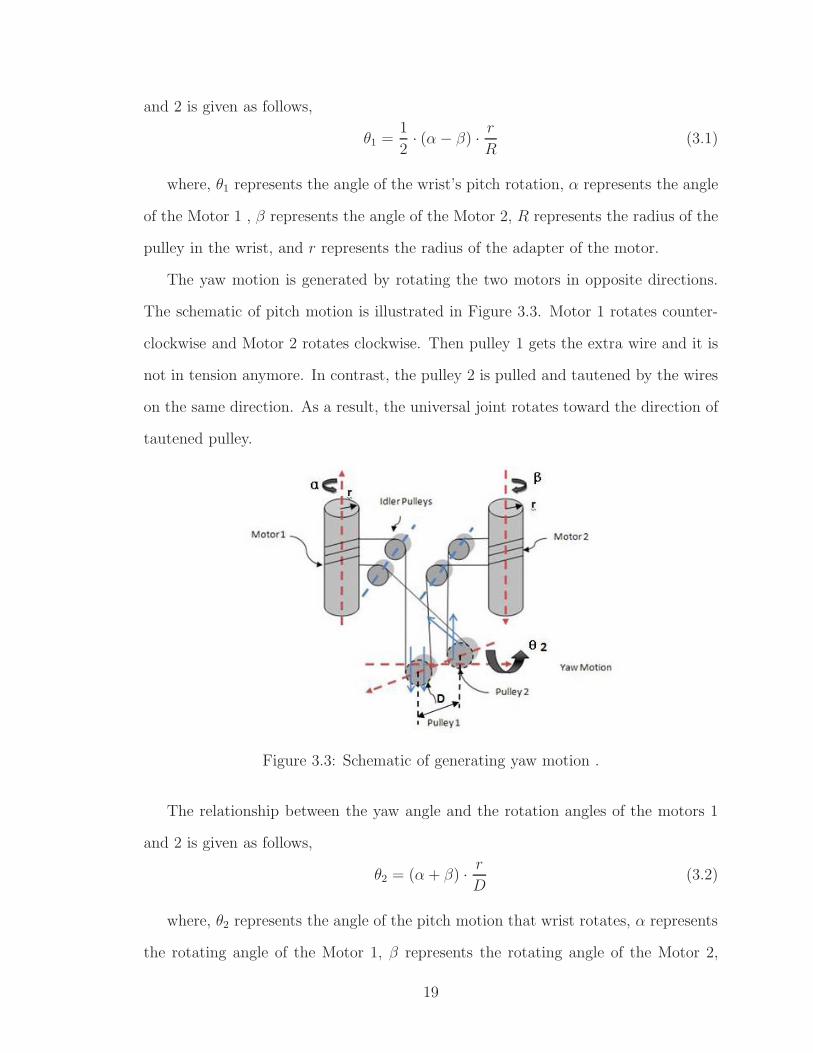
The yaw motion is generated by rotating the two motors in opposite directions.
The schematic of pitch motion is illustrated in Figure 3.3. Motor 1 rotates counter-
clockwise and Motor 2 rotates clockwise. Then pulley 1 gets the extra wire and it is
not in tension anymore. In contrast, the pulley 2 is pulled and tautened by the wires
on the same direction. As a result, the universal joint rotates toward the direction of
tautened pulley.
Figure 3.3: Schematic of generating yaw motion .
The relationship between the yaw angle and the rotation angles of the motors 1
and 2 is given as follows,
θ2 = (α+ β) · r
D(3.2)
where, θ2 represents the angle of the pitch motion that wrist rotates, α represents
the rotating angle of the Motor 1, β represents the rotating angle of the Motor 2,
19

D represents the distance between the two pulleys in the wrist, and r represents the
radius of the adapter of the motor.
20

Chapter 4
Prototype Design
4.1 Kinematics
In this section, the kinematic analysis of the prototype is described. Forward and
inverse kinematics are presented in the following subsections.
4.1.1 Forward Kinematics
The zero configuration and the naming convention is shown in Figure 4.1.
Figure 4.1: Zero configuration of the manipulator.
The kinematic configuration of the manipulator is characterized by the following
21

vectors and points:
ω0 =
[0 0 1
]T(4.1)
ω1 =
[1 0 0
]T(4.2)
ω2 =
[0 1 0
]T(4.3)
q0 =
[0 0 0
]T(4.4)
q1 = q2 =
[0 0 L1
]T(4.5)
ξi =
⎡⎢⎣ −ωi × qi
ωi
⎤⎥⎦ , i = 0, 1, 2 (4.6)
eωiθi = I + ωi sin θi + ωi2(1− cos θi), i = 0, 1, 2 (4.7)
eξiθi =
⎡⎢⎣ eωiθi (I − eωiθi)(ωi × υi) + ωiω
Ti υiθi
0 1
⎤⎥⎦ , i = 0, 1, 2 (4.8)
where υi = −ωi × qi.
The transformation between tool and spatial frames at θ = 0 is given by
gst(0) =
⎡⎢⎢⎢⎢⎢⎢⎢⎣
√22
0√22
√22· (L3)
0 1 0 0
−√22
0√22
(L1 + L2 +√22· (L3))
0 0 0 1
⎤⎥⎥⎥⎥⎥⎥⎥⎦
(4.9)
It can easily be derived that the forward kinematics map of the manipulator is
given by
gst(θ) =
⎡⎢⎣ R(θ) p(θ)
0 1
⎤⎥⎦ (4.10)
22

R(θ) = (4.11)⎡⎢⎢⎢⎢⎣
√22(c0(c2 − s2)− s0s1(s2 + c2)) −s0c1
√22(c0(c2 + s2)− s0s1(s2 − c2))
√22(s0(c2 − s2) + c0s1(s2 + c2)) c0c1
√22(s0(c2 + s2)− c0s1(s2 − c2))
−√22c1(s2 + c2) s1 −
√22c1(s2 − c2)
⎤⎥⎥⎥⎥⎦
p(θ) =
⎡⎢⎢⎢⎢⎣
L2(c0s2 + s0s1c2) +√22L3(c0(s2 + c2)− s0s1(s2 − c2))
L2(s0s2 − c0s1c2) +√22L3(s0(s2 + c2) + c0s1(s2 − c2))
L1 + L2c1c2 +√22L3c1(c2 − s2)
⎤⎥⎥⎥⎥⎦ (4.12)
Here, c0 and s0 are abbreviations for cos θ0 and sin θ0, respectively, and similarly
for the other terms.
The mapping from the angles of motors to the angles of wrist is derived from
equations (3.1) and (3.2) in Chapter 3, as follows:
θ1 = (α + β) · r
D(4.13)
θ2 =1
2· (α− β) · r
R. (4.14)
Finally, the rotating angle of roll motor equals the angle of roll motion. The
equation is given by
θ0 = γ. (4.15)
4.1.2 Inverse Kinematics
In order to solve inverse kinematics problem, we need find the set of (θ0, θ1, θ2)
triples that drives the end-effector to a desired position, in terms of gd, the desired
configuration of the tool frame shown in Figure 4.1. In Section 4.1.1, we have obtained
equations (4.1), (4.2), (4.3), (4.4), (4.5) and (4.9).
23

The equation we wish to solve is given by
gst(θ) = eξ0θ0eξ1θ1eξ2θ2gst(0) = gd. (4.16)
Postmultiplying this equation by g−1st (0) isolates the exponential maps:
eξ0θ0eξ1θ1eξ2θ2 = gdg−1st (0) =: g1. (4.17)
Multiply both sides of (4.17) with point p1 ∈ R3, p1 = [0, 1, L1]
T and p1 =
[0, 1, L1, 1]T , which is at the axis of ξ2, but not at the axis of ξ1 . Since eξ2θ2p1 = p1,
this yields
eξ0θ0eξ1θ1eξ2θ2p1 = eξ0θ0eξ1θ1p1 = g1p1. (4.18)
Substract from both sides of (4.18) a point p0 ∈ R3, p0 = [0, 0, 0]T and p0 =
[0, 0, 0, 1]T , which is the origin of the spatial frame. Since eξ0θ0p0 = p0, this yields
eξ0θ0(eξ1θ1p1 − p0) = g1p1 − p0. (4.19)
Taking the magnitude of both sides of (4.19) gives
‖eξ1θ1p1 − p0)‖ = ‖g1p1 − p0|. (4.20)
Equation (4.20) satisfies Subproblem 3 given in [24], with p = p1, q = p0, and
δ = ‖g1p1−p0‖. The result of θ1 is obtained by solving the Subproblem 3. The result
has either zero, one, or two solutions.
Since θ1 is known, 4.18 becomes
eξ0θ0(eξ1θ1p1) = eξ0θ0p2 = g1p1. (4.21)
24

Applying Subproblem 1 given in [24], with p = p2 and q = g1p1, we can obtain the
value for θ0. Equation 4.21 has one solution.
Since we know the values of θ0 and θ1, the equation (4.17) becomes
eξ2θ2 = e−ξ1θ1e−ξ0θ0g1 =: g2. (4.22)
Multiply both sides of equation (4.22) to the point p0 ∈ R3, p0 = [0, 0, 0, 1]T , which
is not at the axis of ξ2. This gives
eξ2θ2p0 = g2p0. (4.23)
Equation 4.23 is in the form of Subproblem 1 [24], with p = p0 and q = g2p0, we
can obtain the value for θ2. Equation (4.23) has one solution.
At the end, there are a maximum of two possible solutions.
Based on (4.13) and (4.14), the mapping from wrist angles to motor angles is:
α = θ1R
r+ θ2
D
2r(4.24)
β = θ2D
2r− θ1
R
r(4.25)
where, α represents the angle of Motor 1, β represents the angle of Motor 2, θ1
represents the angle of yaw motion, and θ2 represents the angle of pitch motion.
4.2 Description of Prototype’s Mechanical Hard-
ware Components
4.2.1 Universal Joint
In the proposed design, the additional 2 DOF on the distal end of the tool is provided
by adding a 2 DOF universal joint. In this section, the structure of the universal joint
25

and the parts included is presented to illustrate the principle and workspace of the
universal joint.
4.2.1.1 Structure of Universal Joint
A universal joint, also called Cardan joint, is a widely used component transmitting
rotary motion. It consists of two links attached to their respective shafts and con-
nected by means of a spider. The shape of the spider and the link were designed to
meet the design requirements, as shown in Figure 4.2.
Figure 4.2: Universal Joint (Stanley-Proto J5470A).
The schematic of universal joint is shown in Figure 4.3. It is comprised of two links,
upper link and lower link, two pulleys, a shaft and a pin. The links are connected by
a cross-like piece, which is formed by a shaft and a pin. The pin goes through the
pair of pulleys and the shaft. The pin is press fitted to the pulleys and the lower link,
so the pulleys do not rotate relative to the lower link. Additionally, the fit between
the pin and shaft is sliding fit, so that the lower link can rotate along the axis of pin.
Two sleeve bearings are assembled into the shaft and the upper link, so that the shaft
can rotate relative to the upper link.
The shapes of the links are optimized to allow free motion at any direction. They
were machined by electron discharge machining (EDM). The outer diameters of the
links are 8 mm, satisfying the dimension requirement. There is no clearance between
the shaft and the pulleys to prevent unexpected motions.
26

Figure 4.3: Structure of Universal Joint .
4.2.1.2 Workspace of Universal Joint
The workspace of the universal joint is given in Figure 4.4. The range of the pitch
motion is from -90o to 90o . Due to the intrinsic limitation of universal joint, the
range of the yaw motion is from -35o to 35o . In Figure 4.4, the distance from the tip
of the gripper to the axis of the pin in the wrist is 5.5 mm.
4.2.1.3 Material of Universal Joint
In surgery, the universal joint has to enter human body through the skin barrier.
So the materials of universal joint should be taken a full consideration to be bio-
compatible with the human internal environment. Moreover, the tendon will exert
considerable forces on the pulleys and indirectly on the shaft and the pin. So the ma-
terials should be hard enough to suffer the tension from the tendon and also protect
themselves from deformation. In addition, it is better to select the common materials
in design for simplicity.
In the proposed design, the links, the pulleys and the shaft are made out of type
27

−6
−4
−2
0
2
4
6 −10−8
−6−4
−20
24
68
10
−10
−9
−8
−7
−6
−5
−4
−3
−2
−1
0z
[mm
]
x [mm]y [mm]
position
Figure 4.4: Workspace of universal joint
316 stainless steel, which are commonly used in surgical instruments. However, for
the sleeve bearings, stainless steel is not a good choice. Because the sleeve bearing is
located between the joint shaft and the link, both of which are made out of stainless
steels. In order to decrease the friction between them, the coefficient of friction
between the material of the sleeve bearings and type 316 stainless steels should be
smaller than the one between type 316 stainless steel and type 316 stainless steel.
Therefore, PEEK CA30 LSG (QUADRANT, Reading, PA 19612-4235) was a good
choice for the sleeve bearings. The coefficient of friction between stainless steel and
PEEK is smaller than the one between stainless steel and stainless steel. Although
it is a polymer, it has excellent mechanical and chemical resistance properties that
are retained to high temperatures. Also, PEEK CA30 LSG is one of the few plastics
compatible with ultra-high vacuum applications. More importantly, it is widely used
28

in surgical instruments, like endoscopic equipments and minimal invasive products.
4.2.1.4 Current Prototype of Universal Joint
Figure 4.5: Prototype of universal joint
The real prototype of universal joint is shown in Figure 4.5. The sleeve bearings
in black are made of PEEK CA30 LSG. The upper link is connected with the shaft
and the lower link is mounted to the force/torque sensor.
4.2.2 Actuation unit
The actuation unit provides the prototype with the driving forces. Three motors are
mounted in the actuation unit, one for roll motion and other two for wrist motions.
As it was explained in Chapter 3, the power from the actuation is transmitted to the
29

joints by tendons.
4.2.2.1 Selections of Motors and Tendon
A. Selection of motors for the wrist motion
This subsection is about selection of motors for the wrist motion, a combination
of yaw and pitch motions. The motors are used to drive the gripper to insert needle
into the organ tissue during surgery. Okamura et al. [11] has developed a force
model for needle insertion into soft tissue, which showed that the forces were more
than 1.5 N and less than 2.5 N during the needle insertion and removal. The design
specification for needle insertion was chosen as 5 N. As shown in Figure 4.6, the
distance between the center of the wrist and the line along which the insertion force
act, equals (7.874+3+14.5+4+12)×sin(45)=29.25 mm. So the torque that need to be
generated at the wrist to achieve the necessary needle insertion force can be calculated
as 5 N×29.25 mm=146.258 Nmm.
Figure 4.6: Diagram of the calculation of joint force specification from needle insertionforce requirements
The torque and force on the wrist was experimentally measured, using an ATI
30

Figure 4.7: Experiment of measuring torque and force
Nano 17 F/T Sensor mounted on the attachment on the wrist. The Figure 4.7 il-
lustrates the experimental setup. As it can be seen from the figure, the gripper is
fastened tightly on a metal piece, and a plastic piece is placed next to the sensor to
prevent wrist motion, so that stationary forces can be measured.
In this experiment, two Maxon RE 25 precious metal brushes motors were used
to actuate the wrist joints. The nominal torque for the motors is 29.1 Nmm at 12.0
volts. Same torque values were applied to both motors which would rotate in opposite
directions, resulting yaw motion, and the torques were incrementally increased at 1
Nmm steps starting from 0 to 50 Nmm. Then torque values measured by the sensor
were recorded. The collected data and linear fit to the data (R=1.1272) are shown in
Figure 4.8. The line equation is y = 0.4382x−1.5377, where x represents the torques
from motors and y represents the torques measured at wrist by sensor. We mentioned
above that the torque required for the needle insertion was 146.258 Nmm. Using the
line equation, y = 0.4382x−1.5377, the result of x is 337.28 Nmm. Because the wrist
31

design employs 2 motors and the load should be shared by the two motors. So the
required torque per motor should be 337.28÷ 2 = 168.64 Nmm.
0 0.2 0.4 0.6 0.8 1 1.2 1.4 1.6 1.8 2−5
0
5
10
15
20
Motor Current (A)
Tor
que
at W
rist (
N−
mm
)Relationship Between Motor Current & Wrist Torque (Yaw Motion)
DataFit
Figure 4.8: Torque Relationship Between Motor and Wrist (Yaw Motion)
The experiment was then repeated by applying motor torques in the same direc-
tion, yielding the pitch motion. The collected data and linear fit to the data ,which
is y = 5.6795x− 172.1049 (R=13.6750) are shown in Figure 4.9. Required needle in-
sertion torque is 146.258 Nmm. From the line equation, we can calculate the result of
x given y=146.258 Nmm, which is 63.67258 Nmm. Again, since the torque is shared
by two motors, the required torque on each motor is 63.67258÷ 2=31.83629 Nmm.
Based on the measurements and calculations, a combination of Maxon motor
(Part Number 256105) and gearhead (Part Number 218417) was chosen for the wrist
32

1.3 1.4 1.5 1.6 1.7 1.8 1.9 2−10
0
10
20
30
40
50
60
70
80
90
Motor Current (A)
Tor
que
at W
rist (
N−
mm
)
Relationship Between Motor Current & Wrist Torque (Pitch Motion)
DataFit
Figure 4.9: Torque Relationship Between Motor and Wrist (Pitch Motion)
actuation. The nominal speed of motor is 6500 rpm and the stall torque is 3.24 Nmm.
The reduction ratio of gearhead is 64:1. Therefore, the torque the motor can provide
3.24·64=207.36 Nmm, which is sufficient for this prototype to complete the suturing
action. The speed of the motor after the gearhead reduction is 6500 rpm÷64=101
rpm=606 degree/second, which will reach the speed specifications of the yaw and the
pitch motions given in Table 3.1.
B. Selection of motor for roll motion
The selection of the motor depends on how much load it is required to rotate the
instrument and the speed of rotation required reaching the expected bandwidth. The
design schematics of the mechanism are shown in Figures 4.10 and 4.11. The weight
of instrument is estimated to be around 500 g according to selected materials and
volume of parts. Because centers of mass of many parts, including plates, adapter for
33

Figure 4.10: Schematic of actuation unit
roll motor, detachment parts, shaft and upper link are almost on the same axis along
which the roll motor rotates, the instrument could be estimated as a solid cylinder
34

Figure 4.11: Schematic of wrist, sensor and gripper
of radius 20 mm and mass 500 g. The simple model of roll motion is illustrated in
Figure 4.12. The equation of moment of inertia is given as follows:
J =1
8WD2 (4.26)
where J represents moment of inertia (kg·cm2), W represents mass (kg), and D
represents outer diameter (cm). Based on (4.26), the moment of inertia of instrument
along roll motor’s rotation axis is 22 ·0.5÷2=1 kg· cm2. The instrument is desired to
35

Figure 4.12: Simple model of roll motion in order to calculate moment of inertia andload torque
achieve the speed of roll motion at 540o/s, then the rotation speed equals 2·2·60 = 120
rpm =720o/s. As mentioned in subsubsection 4.2.2.1 A, Maxon motor (Part Number
256105) and gearhead (Part Number 218417) can reach 110 rpm at nominal speed.
For convenience, it is desirable to use the same motor selected for the roll motion.
As such, it is necessary to verify that this motor satisfies the specifications of the roll
motion. The maximal diameter of actuation unit is 40 mm. The equation of load
torque of instrument is given as follows:
T = J · ω =J
9.55× 10⁴· Nt(N ·mm) (4.27)
where, T represents the torque, ω represents the angular acceleration (rad/s2), N
represents rotating speed (min−1), J represents moment of inertia of instrument (kg·cm2), and t represents the time (s) that motor needs to accelerate the load inertia of J
up to a speed N . Compared with the inertia of the load, the motor and the gearhead
36

inertia, 0.007 kg· cm2, is ignored. t is assumed to be 0.05 s. So that the load torque
is given by T=0.01256 Nm =12.56 Nmm. As presented above, the combination of
motor selected for wrist motions can provide 207.36 Nmm torque. It is clear that this
motor and gearhead pair is suitable for roll motion as well.
C. Selection of tendon
As discussed in Chapter 3, a tendon drive mechanism was chosen for power trans-
mission. In this subsection, the choice of a qualified cable to meet design requirements
is discussed. First of all, the size of the cable is considered to be a critical factor. In
this design, due to the miniature nature of the prototype, the size of the cable should
also be in the range of 0.015 to 0.025 inches in diameter. The second important factor
is the strength of the cable. The motors can produce 80 N forces exerted on the cable.
Therefore, the strength of the cable should be at least 25 lbs. Another factor is bend
radius of the cable. All cable manufactures specify the minimum bend radius of every
cable. Because the cable will be rolled around the pulley, the minimum bend radius
of the selected cable should meet the diameters of the pulley.
There are a multitude of different materials used to manufacture cables. Stainless
steel is the most common material used for miniature cables. Another metal cable
is tungsten wire utilized in light bulb filaments. Tungsten cables are not as widely
available when compared to stainless steel cables, and they are not biocompatible.
Many synthetic fiber cables are also available, like Spectra fiber, Vectran fiber, and a
high-density polyethylene used for fishing line. In this design, type 302 stainless steel
cable (Part Number 3458T86, McMASTER-CARR, Aurora, Cleveland. 44202-8087),
with 7×3 strand core construction, 0.018 in diameter, 40 lbs breaking strength and
13/32 inches bend radius was chosen.
4.2.2.2 Current Prototype of Actuation Unit
The Figure 4.13 gives the front view of the actuation unit. The roll motor is located
on the top and center of actuation unit. Two other motors for wrist motions are
37

Figure 4.13: Actuation unit prototype
placed on the sides of the roll motor. The diameter of actuation unit is 40 mm. Two
slender and long adapters with outer threads are respectively mounted on the shafts
of the motors. As it can be seen from the figure, the pulleys are mounted on the
pulley supports and the cable is on the pulleys and the adapters. The cable goes
around the threads on the adapters and goes through the shaft to the wrist and come
back to go by the pulleys to form a closed loop. Two motors use this closed cable
loop to transmit the power to the wrist. There are two PCB circuit boards mounted
38

on the actuation unit to connect the cables of the motors.
4.2.3 Gripper
Throughout the course of a surgery, a number of different surgical tools may be used
depending on tasks being performed. In this thesis, we just concentrate on the needle
holder as our surgical tool. Kode [10] in our lab designed a gripper using an integrated
hybrid shape memory alloy and DC micromotor actuation scheme. In his design, the
DC micromotor was mounted to the gripper and SMA wires were used to strengthen
the gripping force. The length of the gripper was 40 mm. Its gripping force was 8 N
and the gripper cycle time was 1.8 second. In this prototype, the goal was to develop
a simpler and cheaper gripper actuation mechanism, for benchtop testing of the test
of the robotic system. As such, the gripper actuation mechanism may not necessarily
work in vivo in a clinical setting, with the understanding that a variant of the design
of Kode [10] will be adopted in the final system. The design, nevertheless, need to
achieve sufficient gripping forces for needle grasping. For convenience of fabrication,
the tip from a laparoscopic in line needle holder (Summit TR7202 Needle Holder
5mmX35cm, Summit Surgical Technologies, Aurora, Co 80014) shown in Figure 2.3
and Figure 4.14 was cut and integrated as the end-effector. This needle holder has
a 5 mm diameter with straight jaw and a Tungsten Carbide tip for holding needle
tightly. To shorten the length of gripper and decrease the weight, the actuator was
moved out of the gripper to ground and connected by a cable transmission.
4.2.3.1 Mechanical Structure of Gripper
The mechanical structure of the gripper is illustrated in Figure 4.15. The inside
dimension of the tip in the figure may be not exactly precise. They are estimated
according to outer dimensions. The cross-section of the gripper shown in Figure 4.16
just illustrates the work principle of gripper and should not be measured for accurate
calculations.
39

As it can be seen in the cross-section figure of the gripper, the upper jaw is con-
nected with a shaft and link mechanism to the actuation. A housing covers the end of
the gripper and is attached to gripper with two 0-80 set screws. A 115 lbs thrust linear
actuator (Part Number HDA2.00-.50, Servocity), located on the ground is used to ac-
tuate the gripper. Force transmission from actuator to gripper is supplied by flexible
transmission, which includes a 0.018 in diameter, 7×3 stainless steel cable (Part num-
ber 3458T86, McMASTER-CARR, Aurora, OH) running through Abrasion-Resistant
White ETFE tubing (Part number 5583K41, McMASTER-CARR, Aurora, OH). The
cable is tied to the end of the gripper shaft and goes through a tiny hole on the center
of the housing’s bottom and also fastened to the end of the shaft of a linear actuator.
This tubing is not biocompatible and will need to be replaced by a biocompatible ma-
terial, if the mechanism needs to be used in vivo. In the housing, a soft compression
spring (Part Number 9435K22, McMASTER-CARR, Aurora, OH) is placed between
the bottom of the housing and a nut mounted on the shaft of gripper. This spring
is intended for opening the gripper. Two holders shown in figure 4.16 will clamp the
gripper to the instrument by screwing together. These two holders are mounted on
the bottom of F/T sensor.
4.2.3.2 Gripper Actuation
The gripper has only 1 DOF and just two simple stages for gripper actuation, closing
and opening. In the current design, an off-the-shelf linear actuator is used to actuate
Figure 4.14: Tip of Summit TR7202 Needle Holder
40

Figure 4.15: Schematic of gripper
Figure 4.16: Schematic of gripper actuation
the gripper. As this actuator is located at the robot base, size is not a major concern.
The operation principle of the gripper is as follows:
The closing action of the needle holder jaw is shown in Figure 4.17. In the figure,
the shaft of the linear actuator moves backward and pulls the wire rope, leading to
the leftward movements of the shaft and the link of the tip. Consequently the upper
jaw will rotate clockwise until it touches the lower jaw tightly. At the same time, the
nut on the shaft of the tip will compress the spring backward as well. Although the
stroke of the gripper is only 1 mm, due to the flexibility of the cable and the tubing,
41
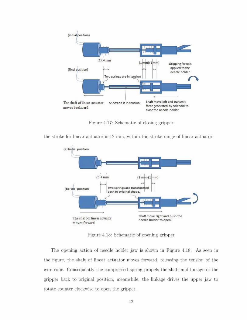
Figure 4.17: Schematic of closing gripper
the stroke for linear actuator is 12 mm, within the stroke range of linear actuator.
Figure 4.18: Schematic of opening gripper
The opening action of needle holder jaw is shown in Figure 4.18. As seen in
the figure, the shaft of linear actuator moves forward, releasing the tension of the
wire rope. Consequently the compressed spring propels the shaft and linkage of the
gripper back to original position, meanwhile, the linkage drives the upper jaw to
rotate counter clockwise to open the gripper.
42

4.2.3.3 Current Prototype of Gripper
The prototype of gripper is shown in Figure 4.19. The diameter of the gripper is 6.10
mm, the length is 32.30 mm and the weight is 7.3 g. The gripper is clamped by the
holders mounted on the F/T sensor. The gripper mechanism can be easily replaced
by unfastening the clamps. The gripper makes a 45o angle with the shaft and the
force/torque sensor for ease of operation, by reducing the wrist to gripper distance.
Figure 4.19: Prototype of gripper
43

4.2.4 Detachment
Figure 4.20: Left : Schematic of detachment part 1, Right : Schematic of detachmentpart 2
The sterilization of the instrument is at high importance. In the operation rooms,
every surgical tool is required to be sterilized. The proposed design is intended to
be reusable after sterilization. In general, surgical instruments entering the human
body must be sterilized to a high sterility assurance level. Usually they are steril-
ized in autoclave under high pressure steam at 121oC or higher. The motors in the
actuation unit are not suitable for sterilization by high temperature and pressure.
Because the maximum permissible winding temperature for Maxon RE 10 motors
is +85oC. Therefore, the instrument has been designed such that the actuation unit
does not actually need to be sterilized in autoclave as this unit does not need enter
the human body. This is achieved by designing a detachment mechanism to detach
the components that would be subjected to sterilization in autoclave from actuation
44

unit. The two parts after separation are shown in Figure 4.20. The detachment is
achieved by just unscrewing five screws. The actuation unit could be wrapped by
sterilized plastic bag during surgery and, if necessary, sterilized by other sterilization
method after surgery, such as gas plasma.
4.3 Description of Prototype’s Electrical Hardware
Components
In order to drive the prototype, three Maxon RE 10 motors (Part Number 256105)
with built-in encoders are used. Three Maxon LSC 30/2 4-Q-DC servoamplifiers are
used to drive these motors. Additionally, with the aim of outputting desired current
from amplifier to motor, a Measurement Computing PCI-DDA08/12 board, with 8-
channel, 12 bit analog output and 48 bits digital I/O is chosen to control signals
to the amplifiers. The digital signals on the PCI-DDA08/12 are used to control
emergency software switches. A National Instruments PCI-6602 counter board is
used to count position signals from encoders to measure accurate rotating angles of
motors. Furthermore, one PCB board to connect PC boards with amplifiers and
another board to connect encoders with amplifiers were designed. These components
are discussed in Appendix A.
4.4 Control Design
The next step of the prototype design is the design of the motion controllers. The
following subsections present the wrist and gripper controller designs.
4.4.1 Wrist Motion Control
In this prototype, the wrist motions are controlled using a joint level proportional-
integral-derivative (PID) control scheme, a method widely used in control systems.
45

The flow chart of the position control of the wrist motors is illustrated in Figure 4.21.
Figure 4.21: Flow chart of position control of Maxon motors
As discussed in section 4.3, the input-output relationship of the motor-amplifier
are in the form:
U = aI + b (4.28)
where a and b are experiment determined coefficients, U represents analog voltage
input, and I represents analog current output.
For DC motor, there is a linear relationship between torque τ and current I
characterized by a torque constant K:
τ = KI. (4.29)
Consequently, we can obtain
U = a · τ/K + b (4.30)
by substituting equation (4.29) into equation (4.28).
Equation of error, e = (r − m) , where e represents error, r represents reference
position, and m represents actual position measured from encoder, is shown in Figure
4.22. By using PID control, we intend to minimize the error to a minimum values by
selecting the proportional, the integral and derivative values, Kp, Ki, Kd respectively
and appropriately. From the Figure 4.22, equation of torque
46

Figure 4.22: Flow chart of PID control of Maxon motors
τ = Kpe(t) +Ki
∫e(τ)dτ +Kd
de(t)
dt(4.31)
can be derived based on principle of PID control. Finally, we get the equation of
voltage for amplifier by substituting equation (4.31) into equation (4.30)
U = a(Kpe(t) +Ki
∫e(τ)dτ +Kd
de(t)dt
K) + b, (4.32)
where, e = (r −m).
The PID controller was implemented using LabView software (National Instru-
ment,Austin, TX 78759-3504).
4.4.2 Gripper Control
The gripper actuation is controlled using a PD controller. The flow chart of PD
position control of linear actuator is shown in Figure 4.23 and is similar to Figure
4.21. NI DAQPad-6015 obtains the position of the linear actuator in real-time using
the integrated potentiometer. By PD control, the error between the reference position
and actual position of linear actuator is converted to a voltage value. Then the NI
DAQPad-6015 outputs this voltage to Maxon LSC 30/2 Amplifier, which drives the
linear actuator.
47
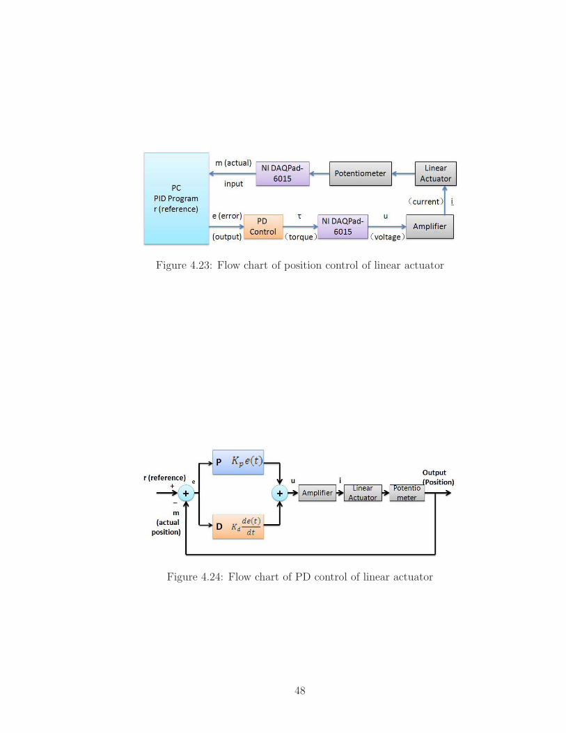
Figure 4.23: Flow chart of position control of linear actuator
Figure 4.24: Flow chart of PD control of linear actuator
48

Chapter 5
Test Results of the Prototype
In this chapter, the results of the tests performed to evaluate the constructed proto-
type is presented.
5.1 Test Results of Wrist
5.1.1 Range of Motion
The first test performed was to evaluate the range of motion of the individual joints of
the wrist. Using the position controller with 200 Hz sampling rate, the same reference
angular positions were input to both wrist motors and incrementally increased at
1o steps, resulting pitch motion. The results showed that the wrist can pitch about
axis 1 by ±90◦. Then, reference angular positions in opposite directions were applied,
leading to yaw motion, and also incrementally increased at 1o steps. The results
showed that the wrist can yaw about axis 2 by ±35◦. The roll axis was also similarly
tested, which showed that the instrument can roll about axis 0 by ±360◦, as shown
in Figure 5.1.
49

Figure 5.1: Schematic of 3 DOF motions
5.1.2 Speed of Motion
The second test performed was to evaluate the speed of motion of the wrist joint.
Using the PD controller described in Section 4.4, the prototype’s roll motion was
actuated to rotate to any desired position. The test showed that rolling from −360◦
to 360◦ took 1 s. In other words, the speed of roll motion was 720◦/sec. The speeds of
the other wrist joints were tested using a similar procedure. The results showed that,
the wrist pitched from 0 to 45◦ in approximately 0.5 s and yawed from 0 to 30◦ in
approximately 0.5 s. Hence, the maximum angular velocities were identified as 90◦/s
and 60◦/s for the pitch and yaw axes.
5.1.3 Test Wrist Rotation
The third test performed was to evaluate the performance of wrist rotation. Rotating
a circle around the central point of wrist was chosen as the target wrist motion.
Polaris Vicra optical sensor (NDI, Northern Digital Inc, Waterloo, Ontario, Canada)
50

was used to track the trajectory of wrist’s central point. Using the position controller
with 154 Hz sampling rate, the reference angular positions were input to both wrist
motors. The 2d trajectory of wrist rotation is shown in Figure 5.2 and 3d trajectory
is shown in Figure 5.3.
Based on forward kinematics of instrument and the mapping from motor angles
to wrist angles presented in Section 4.1.1, using the reference angular positions, the
desired trajectory is the red circle shown in Figure 5.2. The blue trajectory is drawn
based on actual angular data from encoders. The black trajectory in dash line is
recorded by optical sensor.
−15 −10 −5 0 5 10 15
−10
−5
0
5
10
15
x [mm]
y [m
m]
Optical DataEncoder DataEncoder Reference
Figure 5.2: 2D trajectory of wrist rotation
5.1.4 Test Force and Torque
The next test performed was to measure the force capabilities of the wrist joints. An
ATI 6 axis force/torque sensor (Type SI-25-0.25) was used to measure the forces and
51

−10
0
10−10
−50
510
15
−2
0
2
4
6
y [mm]x [mm]
z [m
m]
Optical DataEncoder DataEncoder Reference
Figure 5.3: 3D trajectory of wrist rotation
torques of the instrument. The specifications of this sensor is shown in Table 5.1.
Table 5.1: Specification of force/torque sensorSensing Ranges Resolution
Fx, Fy Fz Tx, Ty Tz Fx, Fy Fz Tx, Ty Tz25N 35N 250Nmm 250Nmm 1/160N 1/160N 1/32Nmm 1/32Nmm
The experiment setup was the same with the one shown in Figure 4.7. The
instrument was fixed to a metal piece with a screw and the sensor was mounted on
the wrist attachment. A plastic piece was fixed next to the sensor to prevent wrist
motion, so that blocking forces can be measured. For wrist to be in static equilibrium,
the sum of the torques about any point must be zero. The equation of the sum of
the torques at the center of wrist joints is given as:
∑τ = τw + τs = 0, (5.1)
where τw represents the wrist joint torques and τs represents the torques measured
52
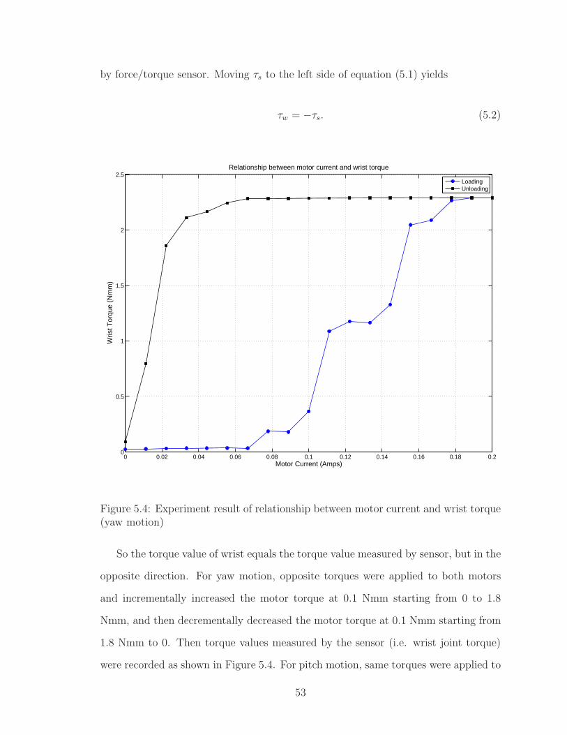
by force/torque sensor. Moving τs to the left side of equation (5.1) yields
τw = −τs. (5.2)
0 0.02 0.04 0.06 0.08 0.1 0.12 0.14 0.16 0.18 0.20
0.5
1
1.5
2
2.5
Motor Current (Amps)
Wris
t Tor
que
(Nm
m)
Relationship between motor current and wrist torque
LoadingUnloading
Figure 5.4: Experiment result of relationship between motor current and wrist torque(yaw motion)
So the torque value of wrist equals the torque value measured by sensor, but in the
opposite direction. For yaw motion, opposite torques were applied to both motors
and incrementally increased the motor torque at 0.1 Nmm starting from 0 to 1.8
Nmm, and then decrementally decreased the motor torque at 0.1 Nmm starting from
1.8 Nmm to 0. Then torque values measured by the sensor (i.e. wrist joint torque)
were recorded as shown in Figure 5.4. For pitch motion, same torques were applied to
53

both motors and the motor torques were incrementally increased at 0.1 Nmm steps
starting from 0 to 1.8 Nmm, and then decrementally decreased the motor torque at
0.1 Nmm starting from 1.8 Nmm to 0. Then the torque values measured by the sensor
(i.e. wrist joint torque) were recorded as shown in Figure 5.5.
0 0.02 0.04 0.06 0.08 0.1 0.12 0.14 0.16 0.18 0.20
0.5
1
1.5
2
2.5
Motor Current (Amps)
Wris
t Tor
que
(Nm
m)
Relationship between motor current and wrist torque (Pitch Motion)
LoadingUnloading
Figure 5.5: Experiment result of relationship between motor current and wrist torque(pitch motion)
5.1.5 Discussion
As it can be seen in Figure 5.2, the blue trajectory based on actual angular positions
from encoders is not smooth. One possible reason is that due to the limitation of the
operating system used in implementation of the control algorithms, the sampling rates
54

of the control program could not be improved, which limited the control performance.
In the future, if the control program can be implemented using a real-time operating
system, such as XPC, the instrument would perform better. Additionally, there is a
gap between trajectory of wrist rotation and desired trajectory, the black trajectory
and red one shown in Figure 5.2. This problem could be caused by the rubbing of
the cable inside shaft, which increased the friction. Another possible reason is tendon
slipping, which was observed on the wrist’s pulleys while the wrist was rotating. The
reason of this problem is that the friction between the cable and the pulleys are too
small. In order to increase the friction to reduce slipping, the cable was wrapped
around the pulleys one more loop, which increased the contact surface between the
cable and pulley. Another way to reduce slipping would be to increase the tension
on the cable to increase the friction. However, the increased friction would increase
the load on the actuators and potentially reduce the performance of instrument. So
the balance between the friction and performance should be determined based on a
series of experiments.
The result of wrist torque shown in Figure 5.5 and 5.4 showed that the actuation
power from motors is lost drastically during tendon transmission through the 8 mm
diameter instrument shaft. One possible reason of this is the rubbing of the cable
inside shaft. If more forces at the needle tip are desired, cable guide plates can be
used to prevent rubbing.
5.2 Test Results of Gripper
5.2.1 Gripping Force
The aim of this experiment is to test the gripping force of the gripper, which is defined
as the force to clamp needle exerted by gripper’s jaws, perpendicular to the surface of
jaws. A 0-90 N force gauge (AccuForce, Mansfield and Green Division of AMETEK)
is used to measure gripping force. The experiment setup is shown in Figure 5.6. Force
55

Figure 5.6: Experiment setup of measuring gripping force of gripper
gauge is mounted on a 1.75” single axis translation stage (Edmund Optics), which
can move linearly. The gripper is tightly fixed with a screw in a support piece. A wire
is connected between the tip of force gauge and the upper jaw of gripper. There are
two ways to measure gripping force. One way is that when the gripper is closed by
the pulling of actuator, the gauge is moved backward with translation stage until the
upper jaw opens. Another way is to keep the gauge still, then actuate the actuator
to try to close the jaw.
In this test, two positions were chosen to place the needle. To simplify naming
convention of these positions, they were called as position 1 and position 2, as shown
in Figure 5.7. The length of jaw was defined as L. The fourth line from left to right
in the figure represents 0 position and the first line represents a position away from 0
position at a distance of L. So position 1 was located on a position from 0 a distance
of 0.75L and position 2 was placed on a position from 0 a distance of 0.5L.
At the first, the gripping force of the TR7202 needle holder, which is used in MIS,
was tested. The needle was placed on position 1, as shown in Figure 5.7. There
were four clamping positions on this needle holder. The results of the gripping forces
56

Figure 5.7: Schematics of needle’s positions in gripper
Table 5.2: TR7202 needle holder’s performancesLevel Gripping force1 26.8 N2 45.8 N3 64.0 N4 80.0 N
versus clamping positions were given in Table 5.2. Then a performance test for
suturing actions using this needle holder and a curved needle placed on position 1
was conducted using a phantom tissue [12], a square sample of silicone rubber (RTV
6186, Momentive) with behavior similar to soft tissues. This test was performed by
the needle holder with 26.8 N gripping force. The experiment result showed that
exerted 26.8 N gripping force on the curved needle, the needle insertion into this
phantom tissue could be completed successfully.
A linear actuator (Part number HDA2.00-.50, Servocity) was used to actuate the
gripper. The maximum thrust force of actuator is 511.5N (115 lbs.) at 12 Volts.
Force transmission between the gripper and the linear actuator was supplied by a
flexible transmission, which is composed of a stainless steel wire and a plastic tubing.
Because of the size of the gripper, there are limited choices for stainless steel wire
selection. The diameter of the wire cannot be larger than 0.020”. This restriction
limited the choices for the tubing. Initial tests with the available tubing failed due
to large forces provided by the actuator. The ends of the tubing (Part Number
57

Table 5.3: Specifications of tubingTubing Type Inside Diameter Outside Diameter Hardness
Silicone rubber 0.0625” 0.292” 60A (Shore A)High-pressure nylon 0.073” 0.125” 108 (Rockwell R)Nylon vacuum 0.078” 0.125” 112 (Rockwell R)White ETFE 0.020” 0.0625” 63D-72D (Shore D)
5583K42, McMASTER-CARR, Aurora, OH) mentioned in subsection 4.2.3.1 were
damaged due to its thin wall thickness. Since tubing with larger wall thickness were
not available, a larger tubing was used to reinforce the small diameter tubing by
inserting the small tubing into the larger one. Three kinds of outer tubing were
chosen for testing with the inner tubing. These are high-purity white silicone rubber
tubing (Part number 51735K21, McMASTER-CARR, Aurora, OH), high-pressure
white Nylon 11 tubing (Part number 9685T103, McMASTER-CARR, Aurora, OH)
and Nylon Vacuum tubing (Part number 5173K914, McMASTER-CARR, Aurora,
OH). The specifications of these tubing are listed in Table 5.3.
Experiments showed that this solution can solve the problem and gripper can
open smoothly. Although all three of the tested tubing attained the goal of smooth
gripper operation, the performances were different. The two hard tubing suffered
some minor deformation. Due to softness of material and braid-reinforced structure,
silicone rubber tubing can absorb the deformation by transforming itself. But this
tubing was heaviest and biggest among them. Therefore, White ETFE Tubing as
inner tubing and High-pressure Nylon tubing as outer tubing were chosen for flexible
transmission because this outer tubing not only can facilitate smooth opening, but it
is also lightweight and smaller in diameter.
One important effect observed was the reduction of the gripping force, when the
flexible transmission with double tubing is used. In order to identify the source of the
gripping force reduction, gripping force under flexible transmission mentioned above,
direct non-flexible transmission but with gripper cap and springs, and finally, direct
58
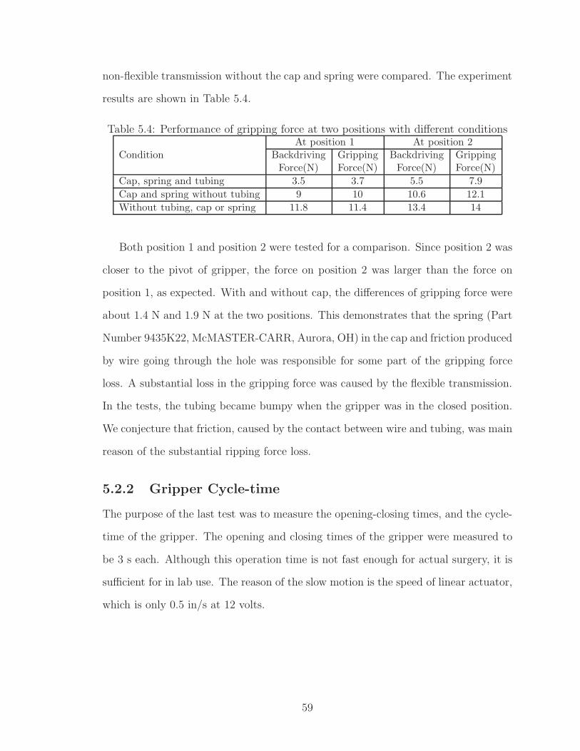
non-flexible transmission without the cap and spring were compared. The experiment
results are shown in Table 5.4.
Table 5.4: Performance of gripping force at two positions with different conditions
ConditionAt position 1 At position 2
Backdriving Gripping Backdriving GrippingForce(N) Force(N) Force(N) Force(N)
Cap, spring and tubing 3.5 3.7 5.5 7.9
Cap and spring without tubing 9 10 10.6 12.1
Without tubing, cap or spring 11.8 11.4 13.4 14
Both position 1 and position 2 were tested for a comparison. Since position 2 was
closer to the pivot of gripper, the force on position 2 was larger than the force on
position 1, as expected. With and without cap, the differences of gripping force were
about 1.4 N and 1.9 N at the two positions. This demonstrates that the spring (Part
Number 9435K22, McMASTER-CARR, Aurora, OH) in the cap and friction produced
by wire going through the hole was responsible for some part of the gripping force
loss. A substantial loss in the gripping force was caused by the flexible transmission.
In the tests, the tubing became bumpy when the gripper was in the closed position.
We conjecture that friction, caused by the contact between wire and tubing, was main
reason of the substantial ripping force loss.
5.2.2 Gripper Cycle-time
The purpose of the last test was to measure the opening-closing times, and the cycle-
time of the gripper. The opening and closing times of the gripper were measured to
be 3 s each. Although this operation time is not fast enough for actual surgery, it is
sufficient for in lab use. The reason of the slow motion is the speed of linear actuator,
which is only 0.5 in/s at 12 volts.
59

Chapter 6
Conclusion
6.1 Summary
This thesis presents a three DOF robotic wrist mechanism with force feedback for
a robotic surgery system. This prototype solves the problem of limited dexterity of
traditional surgical tools in MIS caused by small incision acting as a fulcrum. The
prototype improves dexterity by integrating a 2 DOF wrist on the instrument tip.
Another problem of the current surgical tools in MIS is that they cannot provide force
feedback from the instrument/tissue interaction. Integrated with a 6 axis force/torque
sensor, the designed instrument can provide accurate force and torque measurements
on the instrument tip during instrument/tissue interaction. The shaft has an 8 mm
diameter shaft. The 3 DOF instrument can roll ±360o, pitch ±90o, and yaw ±35o,
hence the workspace of the end-effector is a semisphere. The gripper can provide
5.5 N gripping force. The diameter of the gripper is approximately 6.10 mm, its
length is 32.3 mm and it weights 7.3 g. The angle of gripper jaw opening is 45o. The
end-effector can be easily replaced by different surgical tools depending on task being
performed.
60

6.2 Future Work and Improvements
The dexterity of the universal joint could still be improved. As mentioned earlier,
yaw motion can only extend to ±35o due to physical limitations of the universal joint,
which restricts dexterity of the wrist motion. One option to improve the range of the
wrist motion is to assemble two universal joints together, so that pitch motion of the
wrist can be reached approximately ±180o and yaw motion can be extended to ±70o.
This solution drastically extends the workspace of the wrist and noticeably increases
its dexterity.
The current gripper still needs to be improved to be used in in vivo studies.
Gripping force could be increased by incorporating a mechanical gain mechanism,
such as lever at the end of gripper. Additionally, once the gripping force is increased
to reach the requirements, replacing the linear actuator with a faster actuator can
decrease the cycle-time of the gripper to lower than 1 s. If a custom gripper could be
designed, it can decrease the overall length of the end-effector and can increase the
amount of gripping force.
The present research was only focused on the design of a 3 DOF instrument with
a 2 DOF dexterous wrist mechanism. Future research concentration will be placed on
the design of a base manipulator, on which the designed instrument will be mounted.
This base manipulator will have 3 active DOF and 2 passive DOF, providing sufficient
dexterity to the end-effector and accommodate entry point constraints to complete
different surgical task. Once the whole robotic surgery system is set up, the suturing
action would be tested on phantom tissues and then in in vivo tissues.
61

Appendix A
Electrical Hardware Components
A.1 Amplifiers
The LSC 30/2 is a linear 4-Q-Servoamplifier. The supply voltage is 12-30 VDC
and the maximum output current is 2 A. Current control was chosen as the operating
mode of the amplifiers and input set value range from -10 V to 10 V. Input and output
pinouts of the amplifier is shown in Table A.1. There are totally four servoamplifiers,
including amplifier 0 for roll motor, amplifier 1 and 2 for universal joint, and amplifier
3 for linear actuator.
For every amplifier, it is valuable to model the linear relationship of input voltage
and output current. A National Instruments PCI-6221 board was used to characterize
the input-output of the amplifier. Input voltage of the amplifier were set to discrete
values of 0V, 0.5V, 1V,1.5V,2V, 3V, 4V, 5V and -0.5V, -1V, -1.5V, -2V, -3V, -4V,
-5V. A Maxon RE-10 DC motor (�118383)with GP-10A Gear Head (�218415) was
selected as a load. In addition, the motor’s shaft was kept stationary while it was
working. While the currents corresponding to the voltages from “+motor” and “-
motor” outputs on the amplifier were measured and recorded.
62

Table A.1: Pinout of AmplifierPin Number output
1 +Motor2 -Motor3 +Vcc4 Gnd5 +Vaux6 -Vaux7 -Set8 +Set9 SigGnd10 Dis IN11 Dis +V12 Ready13 -T/ChA14 +T/ChB15 Gnd16 +Venc
A.1.1 Amplifier 0 for Roll Motor
The data of current and voltage are shown in Table A.2. And the data are fit in
Matlab, as shown in Figure A.1. As it can be seen , the relationship is given by
y0 = 4.5545x0 + 0.0021, (A.1)
where, y0 represents analog input to amplifier 0 and x0 represents current output
from amplifier 0.
63

Table A.2: Relationship between voltage and current of amplifier 0Voltage (V) Current (mA)
0 00.5 1101 2191.5 3292 4393 6584 8775 1096
-0.5 -109-1 -219-1.5 -329-2 -439-3 -659-4 -880-5 -1100
−1500 −1000 −500 0 500 1000 1500−6
−4
−2
0
2
4
6
Current (mA)
Vol
tage
(V
)
Relationship of current & voltage of amplifier 0
Figure A.1: Schematics of relationship of voltage and current of amplifier 0 fit inMatlab
A.1.2 Amplifier 1 and 2 for Universal Joint
The data of current and voltage of amplifier 1 and amplifier 2 are shown in Table A.3
and Table A.4 respectively. And the data are fit in Matlab, as shown in Figure A.2
64

Table A.3: Relationship between voltage and current of amplifier 1Voltage (V) Current (mA)
0 2.20.5 111.71 220.71.5 329.92 4403 6584 8765 1095
-0.5 -105.6-1 -215.4-1.5 -325.3-2 -435-3 -654-4 -874-5 -1094
and A.3. As it can be seen , the relationships are given by
if x1 ≥ 0, y1 = 4.5764x1 − 0.0107, (A.2)
if x1 < 0, y1 = 4.5582x1 − 0.0162, (A.3)
if x2 ≥ 0, y2 = 4.8512x1 − 0.0267, (A.4)
if x2 < 0, y2 = 5.1101x2 + 0.1342, (A.5)
where, y1 represents analog input to amplifier 1 and x1 represents current output from
amplifier 1, and y2 represents analog input to amplifier 2 and x2 represents current
output from amplifier 2.
65

Table A.4: Relationship between voltage and current of amplifier 2Voltage (V) Current (mA)
0 -6.240.5 102.81 215.01.5 321.92 4343 6504 7985 1036
-0.5 -115-1 -226-1.5 -337-2 -447-3 -640-4 -762-5 -1004.7
−1500 −1000 −500 0 500 1000 1500−6
−4
−2
0
2
4
6
Current (mA)
Vol
tage
(V
)
Relationship of current & voltage of amplifier 1
Figure A.2: Schematics of relationship of voltage and current of amplifier 1 fit inMatlab
66

−1500 −1000 −500 0 500 1000 1500−5
−4
−3
−2
−1
0
1
2
3
4
5
Current (mA)
Vol
tage
(V
)
Relationship of current & voltage of amplifier 2
Figure A.3: Schematics of relationship of voltage and current of amplifier 2 fit inMatlab
67

Table A.5: Relationship between voltage and current of amplifier 3Voltage (V) Current (mA)
0 -14.260.5 94.01 202.41.5 310.72 4203 6364 8535 1070
-0.5 -122-1 -231-1.5 -340-2 -448-3 -666-4 -884-5 -1101
A.1.3 Amplifier 3 for Linear Actuator
The data of current and voltage are shown in Table A.5. And the data are fit in
Matlab, as shown in Figure A.4. As it can be seen , the relationship is given by
if x3 ≥ 0, y3 = 4.6114x3 + 0.0661, (A.6)
if x3 < 0, y3 = 4.5981x3 + 0.0627, (A.7)
where, y3 represents analog input to amplifier 3 and x3 represents current output
from amplifier 3.
68
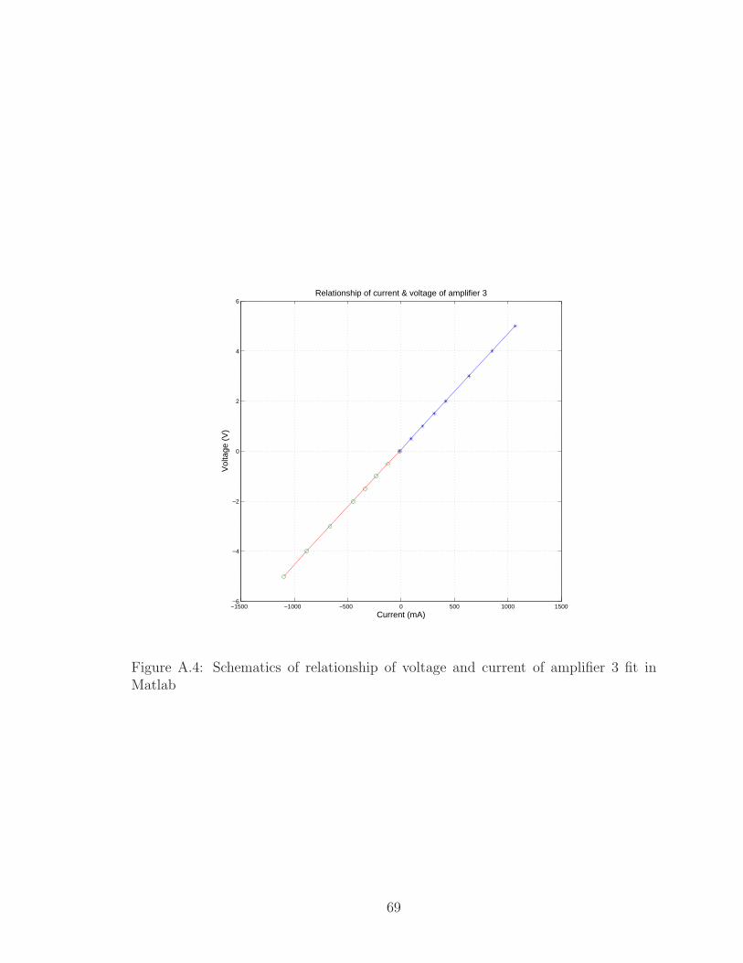
−1500 −1000 −500 0 500 1000 1500−6
−4
−2
0
2
4
6
Current (mA)
Vol
tage
(V
)
Relationship of current & voltage of amplifier 3
Figure A.4: Schematics of relationship of voltage and current of amplifier 3 fit inMatlab
69

A.2 Data Acquisition System
For joint position measurements from motor encoders, a National Instruments PCI-
6602 boards is used. PCI 6602 is an 8-channel, 32-bit counter/timer board. Connector
pinout is shown in figure A.5. Pin 2 “PFI 39/CTR 0 SOURCE” is connected to Chan-
nel 0A from encoder for roll motion and Pin 40 “PFI 37/CTR 0 AUX” is connected
to Channel 0B from encoder for roll motion. Pin 7 “PFI 35/CTR 1 SOURCE” is
connected to Channel 1A from encoder 1 for wrist motion and Pin 6 “PFI 33/CTR
1 AUX” is connected to Channel 1B from encoder 1 for wrist motion. Pin 34 “PFI
31/P0.31/CTR 2 SOURCE” is connected to Channel 2A from encoder 2 for wrist
motion and Pin 66 “PFI 29/P0.29/CTR 2 AUX” is connected to Channel 2B from
encoder 2 for wrist motion.
For analog outputs to the motors, a Measuring Computing DDA08/12 board is
used. DDA08/12 is an 8-channel, 12-bit analog output board with 48 digital I/O
lines. It has a 100-pin output. One purpose of this board is to control set values
input to amplifiers by PC. Another purpose is to use digital signals as emergency
software switches. The connector pinout is shown in Figure A.6. Pin 1 and pin 2 are
for “+set” and “-set” of amplifier 1. Pin 3 and pin 4 are for “+set” and “-set” of
amplifier 2. Pin 5 and pin 6 are for “+set” and “-set” of amplifier 3. Pin 55 is digital
output for roll motion motor. Pin 51 is digital output for motor 1 for wrist motion
and pin 52 for motor 2 for wrist motion.
70

NI 6602 Pinout
1 35
2 36
3 37
4 38
5 39
6 40
7 41
8 42
9 43
10 44
11 45
12 46
13 47
14 48
15 49
16 50
17 51
18 52
19 53
20 54
21 55
22 56
23 57
24 58
25 59
26 60
27 61
28 62
29 63
30 64
31 65
32 66
33 67
34 68
+5 V
PFI 39/CTR 0 SOURCE
PFI 38/CTR 0 GATE
RESERVED
PFI 36/CTR 0 OUT
PFI 33/CTR 1 AUX
PFI 35/CTR 1 SOURCE
PFI 34/CTR 1 GATE
PFI 32/CTR 1 OUT
PFI 0/P0.0
D GND
PFI 3/P0.3
PFI 4/P0.4
D GND
PFI 7/P0.7
CTR 7 OUT/PFI 8/P0.8
PFI 9/P0.9/CTR 7 AUX
D GND
R GND
D GND
PFI 14/P0.14/CTR 6 GATE
PFI 15/P0.15/CTR 6 SOURCE
CTR 5 OUT/PFI 16/P0.16
D GND
PFI 19/P0.19/CTR 5 SOURCE
CTR 4 OUT/PFI 20/P0.20
D GND
PFI 23/P0.23/CTR 4 SOURCE
PFI 24/P0.24/CTR 3 OUT
D GND
PFI 27/P0.27/CTR 3 SOURCE
PFI 28/P0.28/CTR 2 OUT
D GND
PFI 31/P0.31/CTR 2 SOURCE
R GND
RESERVED
RESERVED
PFI 37/CTR 0 AUX
D GND
D GND
R GND
D GND
D GND
PFI 1/P0.1
PFI 2/P0.2
D GND
PFI 5/P0.5
PFI 6/P0.6
D GND
D GND
PFI 10/P0.10/CTR 7 GATE
PFI 11/P0.11/CTR 7 SOURCE
CTR 6 OUT/PFI 12/P0.12
PFI 13/P0.13/CTR 6 AUX
D GND
R GND
PFI 17/P0.17/CTR 5 AUX
PFI 18/P0.18/CTR 5 GATE
D GND
PFI 21/P0.21/CTR 4 AUX
PFI 22/P0.22/CTR 4 GATE
D GND
PFI 25/P0.25/CTR 3 AUX
PFI 26/P0.26/CTR 3 GATE
D GND
PFI 29/P0.29/CTR 2 AUX
PFI 30/P0.30/CTR 2 GATE
D GND
Figure A.5: NI 6602 Connector Pinout
71

Vout 0 12
Vout 1 34
Vout 2 56
Vout 3 78
Vout 4 910
Vout 5 1112
Vout 6 1314
Vout 7 15Ana log G round 16
1718192021222324252627282930313233343536373839404142434445464748
NC 49D igita l G round 50
Ana log G round
Ana log G round
Ana log G round
Ana log G round
Ana log G round
Ana log G round
Ana log G round
NCNCNCNCNCNCNCNCNCNCNCNCNCNCNCNCNCNCNCNCNCNCNCNCNCNCNCNCNCNCNCNC
51 P2-A752 P2-A653 P2-A554 P A455 P A356 P A257 P A158 P A059 P B760 P B661 P B562 P B463 P B364 P B265 P B166 P B067 P C768 P C669 P C570 P C471 P C372 P C273 P C174 P C075 P1 A776 P A677 P A578 P A479 P A380 P A281 P A182 P A083 P B784 P B685 P B586 P B487 P B388 P B289 P B190 P B091 P C792 P C693 P C594 P C495 P C396 P C297 P C198 P C099 +5V100 D ig ital G round
2-2-2-2-2-2-2-2-2-2-2-2-2-2-2-2-2-2-2-2-2-
-1-1-1-1-1-1-1-1-1-1-1-1-1-1-1-1-1-1-1-1-1-1-1-
PC I-DD A08/12 Connector D iagram
Figure A.6: DDA08/12 Connector Pinout
A.3 PCB Boards for Encoder Signals Output
Two custom PCB boards have been designed to combine the signals from three en-
coders and output them to National Instruments PCI 6602 board. For every encoder,
there are 10 pin outputs, shown in Figure A.7. SN75175 IC is recommended as a line
receiver in Maxon catalog for better signal stability. It is a monolithic quadruple dif-
72

ferential line receiver with 3-state outputs. After function of line receiver, Channel A
and Channel A are combined to be one channel. The same thing happens on Channel
B and Channel B. The Vcc and GND from two motors are combined together.
Figure A.7: Encoder Pinout
The first board is designed to combine the two motors for wrist motion. The
schematics of this PCB board is shown in Figure A.8. In the figure, the bold green
line is for GND. After the combination of two encoder signals and processing of SN
75175, there are only 10 pins output left, presented in Table A.6.
Figure A.8: PCB board for two motors
The second board is designed to combine the encoder signals from the motor for
roll motion and the output of the first board. The design principle is the same as the
first board. The schematic is shown in Figure A.8. There are only 16 pins output
left, represented in Table A.7.
73

Table A.6: Pinout of PCB board for two motorsPin Number output
1 +Vcc2 Motor 1+3 Motor 1-4 Motor 2+5 Motor 2-6 Gnd7 Channel 1A8 Channel 1B9 Channel 2A10 Channel 2B
Table A.7: Pinout of PCB board for one motorsPin Number output
1 +Vcc2 Motor0+3 Motor0-4 Motor1+5 Motor1-6 Motor2+7 Motor2-8 Gnd9 Channel 0A10 Channel 0B11 Channel 1A12 Channel 1B13 Channel 2A14 Channel 2B15 N.C.16 N.C.
74

Figure A.9: PCB board for one motor
Figure A.10: Amplifier circuit board
This amplifier circuit board is designed for six motors with six encoders. Three
motors are for base stage of this prototype that will be developed in future research.
Other three motor are used for this prototype. The schematic of this board is shown
75

Table A.8: Pinout of Analog outputSignal Pin Number Encoder Context Control
AO0 1 Analog Output Motor 0AO1 3 Analog Output Motor 1AO2 5 Analog Output Motor 2AO3 7 Analog OutputAO4 9 Analog OutputAO5 11 Analog OutputAO6 13 Analog OutputAO7 15 Analog OutputGND 2,4,6,8,10,12,14,16 Analog Ground GND
Table A.9: Pinout of Digital outputSignal Pin Number Motion Encoder Control 16-Pin Connector ON/OFF
DI 75 Digital Input 15DO0 55 Digital Output Motor 0 1 Switch 1DO1 53 Digital Output 3DO2 51 Digital Output Motor 2 5 Switch 2DO3 52 Digital Output Motor 1 7 Switch 3DO4 54 Digital Output 9DO5 56 Digital Output 11
in Figure A.10. Two 50-pin connectors are mounted for DDA08/12 board. The Table
A.8 represents the pinout of the analog output and the Table A.9 illustrates the pinout
of digital output. A 68-pin connector for PCI-6602 board and the pinout is shown
in Table A.10. A DB25 connector is used to input encoders’ channel signals and the
pinout is shown in Table A.11. A 20-pin connector is for amplifier power supply and
the pinout is shown in Table A.12. Additionally, one 16-pin connector is intended to
output analog signal as set values of amplifier. And another 16-pin located below the
analog output connector is utilized to connect ‘ON/OFF’ swithces.
For the safety of the system, a disable circuits for amplifiers is designed, as shown
in Figure A.11. According to Maxon LSC 30/2 Amplifier’s operating instructions, a
disable circuit with NPN transistor is recommended. If the voltage of “Dis IN” termi-
nal on amplifier is higher than “+Vcc” -1V, the power stage becomes high impedant
and the motor shaft freewheels and slows down. In the design, the disable circuit is
76

Table A.10: Pinout of NI 6602 boardConnector Pin Signal Encoder Context DB25 Cable Pin Counter Contex
1 + 5V + 5V 42 PFI 39 Channel 0A 13 PFI 385 PFI 366 PFI 33 Channel 1B 157 PFI 35 Channel 1A 28 PFI 349 PFI 3210 PFI 011 D GND D GND 1712 PFI 313 PFI 414 D GND15 PFI 717 PFI 9 Channel 7B 2221 PFI 14 3 Counter 6 Gate22 PFI 15 Channel 6A 925 PFI 19 Channel 5A 828 PFI 23 Channel 4A 729 PFI 2431 PFI 27 Channel 3A 632 PFI 2834 PFI 31 Channel 2A 340 PFI 37 Channel 0B 1444 PFI 145 PFI 247 PFI 548 PFI 651 PFI 10 6 Counter 7 Gate52 PFI 11 Channel 7A 1054 PFI 13 Channel 6B 2157 PFI 17 Channel 5B 2058 PFI 18 2 Counter 5 Gate60 PFI 21 Channel 4B 1961 PFI 22 0 Counter 4 Gate63 PFI 25 Channel 3B 1864 PFI 2666 PFI 29 Channel 2B 1667 PFI 3068 D GND
77

Table A.11: Pinout of 25-pin connectorPin Number Signal
1 Channel 0A2 Channel 1A3 Channel 2A4 +5V56 Channel 3A7 Channel 4A8 Channel 5A9 Channel 6A10 Channel 7A11121314 Channel 0B15 Channel 1B16 Channel 2B17 GND18 Channel 3B19 Channel 4B20 Channel 5B21 Channel 6B22 Channel 7B232425
78

Table A.12: Pinout of 20-pin connectorPin Number Signal
1 + 12V2 GND3 Dis IN4 + 12V5 GND6 Dis IN7 + 12V8 GND9 Dis IN10 + 12V11 GND12 Dis IN13 + 12V14 GND15 Dis IN16 + 12V17 GND18 Dis IN19 + 12V20 GND
79

Figure A.11: Amplifier disable circuit
composed of a combination of three switches, including ‘ON/OFF’ mechanical switch,
an emergency software switch corresponding to individual amplifier and an emergency
mechanical switch relating to all amplifiers. 7408 IC And Gate outputs the result of
combination of switch signals to NPN transistor. The signal from And Gate would
be high level and the NPN transistor would open, enabling the amplifier, only when
the ‘ON/OFF’ switches, the emergency mechanical switch are closed, and the digital
signal is at high level. Otherwise, if any of the switches is open, the amplifier would
be disable.
80

Bibliography
[1] M. C. Cavusoglu, W. Williams, F. Tendick, and S. S. Sastry, “Robotics fortelesurgery: Second generation berkeley/ucsf laparoscopic telesurgical worksta-tion and looking towards the future applications,” Industrial Robot, Special Issueon Medical Robotics, vol. 30, no. 1, pp. 22–29, January 2003.
[2] http://www.intuitivesurgical.com/index.aspx.
[3] S. M. Gordon, “New surgical techniques and surgical site infections,” EmergInfect Dis, vol. 7, no. 2, pp. 217–219, March-April 2001.
[4] A. R. Lanfranco, A. E. Castellanos, J. P. Desai, and W. C. Meyers, “Roboticsurgery: A current perspective,” Annals of Surgery, vol. 239, no. 1, pp. 14–21,January 2004.
[5] U. Hagn, R. Konietschke, A. Tobergte, M. Nickl, S. Jorg, B. Kbler, G. Passig,M. Groger, F. Frohlich, U. Seibold, L. Le-Tien, A. Albu-Schaffer, A. Nothhelfer,F. Hacker, M. Grebenstein, and G. Hirzinger, “DLR mirosurge: a versatile sys-tem for research in endoscopic telesurgery,” Int J CARS, vol. 5, no. 2, pp. 183–193, March 2010.
[6] M. O. Schurr, G. Buess, B. Neisius, and U. Voges, “Robotics and telemanipula-tion technologies for endoscopic surgery,” Surgical Endoscopy, vol. 14, no. 4, pp.375–381, April 2000.
[7] N. Simaan, K. Xu, W. Wei, A. Kapoor, P. Kazanzides, R. Taylor, and P. Flint,“Design and integration of a telerobotic system for minimally invasive surgery ofthe throat,” The International Journal of Robotics Research, vol. 28, no. 9, pp.1134–1153, September 2009.
[8] P. Berkelman and J. Ma, “A Compact, Modular, Teleoperated Robotic Min-imally Invasive Surgery System,” in Proceedings of IEEE/RAS-EMBS Inter-national Conference on Biomedical Robotics and Biomechatronics, Pisa Italy,Feburary 2006.
[9] I. V. M. Cenk Cavusoglu and F. Tendick, “Workspace Analysis of Robotic Manip-ulators for a Teleoperated Suturing Task,” in Proceedings of the 2001 IEEE/RSJInternational Conference on Intelligent Robots and Systems, Maui, Hawaii, Oc-tober 2001.
81

[10] V. R. C. Kode and M. C. Cavusoglu, “Design and characterization of a novelhybrid actuator using shape memory alloy and dc micromotor for minimally inva-sive surgery applications,” IEEE/ASME Transactions on mechatronics, vol. 12,no. 4, pp. 455–464, August 2007.
[11] A. M. Okamura, C. Simone, and M. D. OLeary, “Force modeling for needleinsertion into soft tissue,” IEEE transactions on biomedical engineering, vol. 51,no. 10, pp. 1707–1716, October 2004.
[12] M. P. Ottensmeyer, “Minimally invasive instrument for in vivo measurementof solid organ mechanical impedance,” Ph.D Thesis, Massachusetts Institute ofTechnology, 2001.
[13] J. Peirs, D. Reynaerts, and H. V. Brussel, “Design of miniature parallel ma-nipulators for integration in a self-propelling endoscope,” Elsevier, vol. 85, pp.409–417, August 2000.
[14] C. Reboulet and S. Durand-Leguay, “Optimal design of redundant parallel forendoscopic surgery mechanism,” in Proceedings of the 1999 IEEE/RSJ Interna-tional Conference on Intelligent Robots and Systems, 1999.
[15] J.-P. Merlet, “Micro parallel robot MIPS for medical applications,” in Proceed-ings of IEEE Int. Conf. on Emerging Technologies and Factory Automation,Antibes, 2001.
[16] K. Ikuta, S. Daifu, T. Hasegawa, and H. Higashikawa, Hyper-finger for RemoteMinimally Invasive Surgery in Deep Area, ser. Lecture Notes in Computer Sci-ence. Springer Berlin / Heidelberg, 2002, vol. 2488, pp. 173–181.
[17] N. Simaan, “Snake-Like Units Using Flexible Backbones and Actuation Redun-dancy for Enhanced Miniaturization,” in Proceedings of the 2005 IEEE Interna-tional Conference on Robotics and Automation, Barcelona, Spain, 2005.
[18] A. J. Madhanir, G. Niemeyer, and J. K. S. Jr., “The Black Falcon: A Teleoper-ated Surgical Instrument for Minimally Invasive Surgery,” in Proceedings of the1998 IEEE/RSJ Intl. Conference on Intelligent Robots and Systems, Victoria,B.C., Canada, 1998.
[19] U. Seibold, B. Kubler, , and G. Hirzinger, “Prototype of Instrument for Mini-mally Invasive Surgery with 6-Axis Force Sensing Capability,” in Proceedings ofthe 2005 IEEE International Conference on Robotics and Automation,Barcelona,Spain, 2005.
[20] H. Rininsland, “Artemis. a telemanipulator for cardiac surgery,” Eur J Cardio-thorac Surg, vol. 16, pp. S106–S111, November 1999.
[21] M. Minor and R. Mukherjee, “A Dexterous Manipulator for Minimally InvasiveSurgery,” in Proceedings of the 1999 IEEE International Conference on Roboticsand Automation, Detroit, Michigan, 1999.
82

[22] H. Yamashitaa, K. Matsumiyaa, K. Masamunea, H. Liaob, T. Chibac, and T. Do-hia, “Two-dofs bending forceps manipulator of 3.5-mm diameter for intrauterinefetus surgery: Feasibility evaluation,” International Journal of Computer As-sisted Radiology and Surgery, vol. 1, pp. 218–220, June 2006.
[23] K. Yokoi, K. Komoriya, and K. Tanie, “Development of a coupled tendon drivemanipulator with seven degrees-of-freedom,” Control and Information Sciences,vol. 187, pp. 339–346, 1993.
[24] R. M. Murray, Z. Li, and S. S. Sastry, A Mathematical Introduction to RoboticManipulation, 1st ed. 6000 Broken Sound Parkway NW, Suite 300, Boca Raton,FL 33487-2742: CRC Press, 1994.
83