design and prototyping of a new balancing mechanism for
TRANSCRIPT

HAL Id: hal-00451887https://hal.archives-ouvertes.fr/hal-00451887
Submitted on 24 Jun 2019
HAL is a multi-disciplinary open accessarchive for the deposit and dissemination of sci-entific research documents, whether they are pub-lished or not. The documents may come fromteaching and research institutions in France orabroad, or from public or private research centers.
L’archive ouverte pluridisciplinaire HAL, estdestinée au dépôt et à la diffusion de documentsscientifiques de niveau recherche, publiés ou non,émanant des établissements d’enseignement et derecherche français ou étrangers, des laboratoirespublics ou privés.
Design and Prototyping of a New Balancing Mechanismfor Spatial Parallel Manipulators
Cédric Baradat, Vigen Arakelian, Sébastien Briot, Sylvain Guegan
To cite this version:Cédric Baradat, Vigen Arakelian, Sébastien Briot, Sylvain Guegan. Design and Prototyping of a NewBalancing Mechanism for Spatial Parallel Manipulators. ASME, Journal of Mechanical Design, 2008,130 (7). �hal-00451887�
MD-07-1050 1 Corresponding author: Arakelian
Design and Prototyping of a New Balancing Mechanism for
Spatial Parallel Manipulators
C. Baradat *†
, V. Arakelian †, S. Briot
†, S. Guegan
†
* Company: «Intelligent Surgical Instruments and Systems» (ISIS)
20, rue du Tour de l’Eau
F-38400 Saint Martin d’Hères, France
† Departement de Genie Mecanique et Automatique, LGCGM EA3913
Institut National des Sciences Appliquees (INSA)
20, Av. des Buttes de Coësmes, CS 14315,
F-35043 Rennes Cedex, France
Abstract – This paper proposes a new solution to the problem of torque minimization of spatial
parallel manipulators. The suggested approach involves connecting a secondary mechanical system to
the initial structure, which generates a vertical force applied to the manipulator platform. Two versions
of the added force are considered: constant and variable. The conditions for optimization are
formulated by the minimization of the root-mean-square values of the input torques. The positioning
errors of the unbalanced and balanced parallel manipulators are provided. It is shown that the elastic
deformations of the manipulator structure which are due to the payload, change the altitude and the
inclination of the platform. A significant reduction of these errors is achieved by using the balancing
mechanism. The efficiency of the suggested solution is illustrated by numerical simulations and
experimental verifications. The prototype of the suggested balancing mechanism for the Delta robot is
also presented.
Index terms – balancing, torque compensation, parallel mechanisms, Delta robot

MD-07-1050 2 Corresponding author: Arakelian
1. Introduction
A mechanism of parallel architecture is statically balanced if its potential energy is
constant for all possible configurations1. This means that the mechanism is statically stable for
any configuration, i.e. zero actuator torques due to the static loads are required. For static
balancing of robot mechanisms, different approaches and solutions have been developed and
documented [3-41]. The balancing schemes for robotic systems can be systematized by means
of balancing (table 1): counterweight (group A), spring (group B), pneumatic or hydraulic
cylinder, electromagnetic device, etc. (group C). Each group can be presented by the
following subgroups:
A1. Balancing by counterweights mounted on the links of the initial system [3-6]. Such
balancing is very simple to realize. However, it leads to the important increase of the
moving masses of the manipulator, and as a result, its inertia.
A2. Balancing by counterweights mounted on the auxiliary linkage connected with the
initial system [7-10]. Articulated dyads or pantograph mechanism are used as an
auxiliary linkage.
B1. Balancing by springs jointed directly with manipulator links [11-14]
B2. Balancing by using a cable and pulley arrangement [15-18]. Such an approach allows
zero free length springs to be used, which is more favorable for realization of complete
balancing.
Balancing by using an auxiliary mechanism can be presented in the following manner:
B3.1. Balancing by using an auxiliary linkage [19-29].
B3.2. Balancing by using a cam mechanism [30-33].
B3.3. Balancing by using gear train [34-37].
1 It should be noted that, in the balancing of high-speed mechanisms, the term «static balancing» refers to
shaking force cancellation or minimization [1, 2]. With regard to the «static balancing» in robotics, this term

MD-07-1050 3 Corresponding author: Arakelian
Table 1. Balancing schemes for robotic systems A
1
A2
B1
B2
B3
.1
differs from the first definition, because in this case, the aim of the balancing is the minimization or cancellation
of input torques of mechanical system by means of gravitational force balancing.
[3] [4] [5] [6]
[7] [8] [9] [10]
[11] [12] [13] [14]
[15] [16] [17] [18]
[19] [20] [21] [22]

MD-07-1050 4 Corresponding author: Arakelian
B
3.1
B3
.2
B3
.3
C
[38] [39] [40] [41]
[34] [35] [36] [37]
[30] [31] [32] [33]
[26] [27] [28] [29]
[23] [23] [24] [25]
MD-07-1050 5 Corresponding author: Arakelian
C. Balancing by using pneumatic or hydraulic cylinders, which are connected with
manipulator links [38] or directly with the moving platform [39]. There is a balancing
approach based on counterweights, which are fluid reservoirs. Continuous balancing is
achieved by the pumping of the fluid from the first reservoir-counterweight to the
second [40]. Electromagnetic effects were also used for balancing [41].
The literature review showed that many balancing methods are applicable for planar
parallel manipulators. However the balancing of spatial parallel architectures is a complicated
problem because it can be achieved either by unavoidable increase of the total mass of
moving links or by a considerably complicated design of the initial parallel mechanism. Let
us consider this problem for the Delta robot.
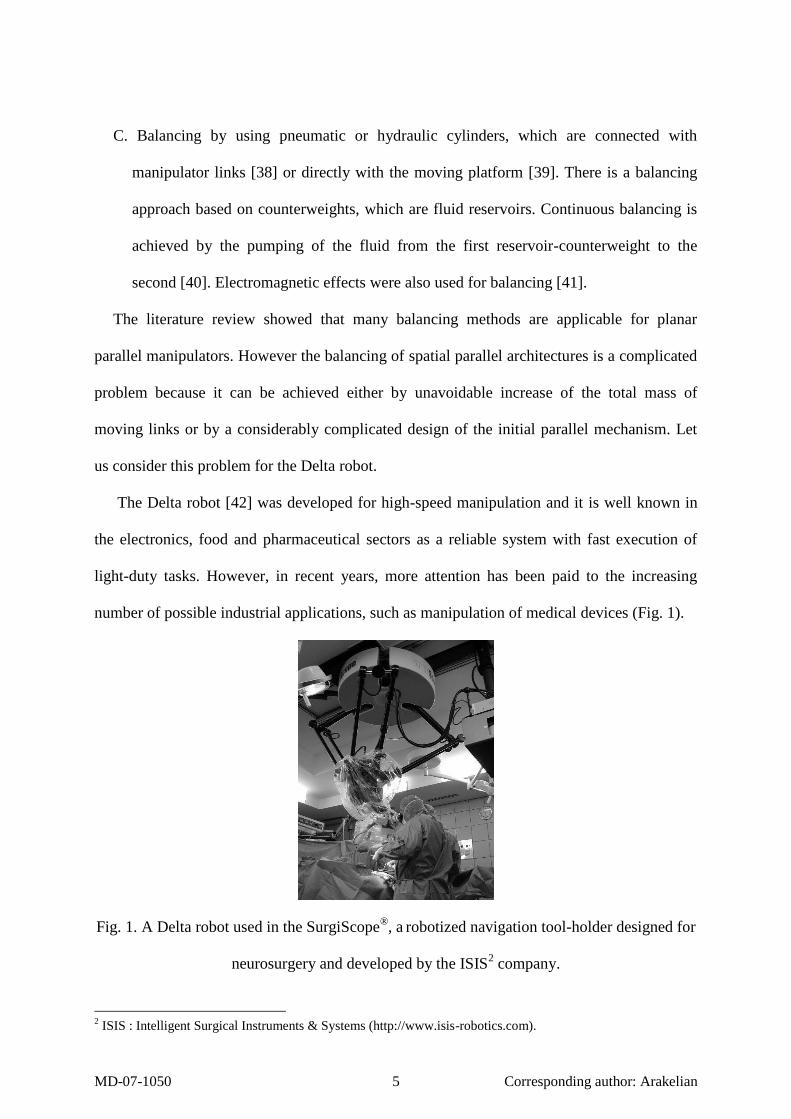
The Delta robot [42] was developed for high-speed manipulation and it is well known in
the electronics, food and pharmaceutical sectors as a reliable system with fast execution of
light-duty tasks. However, in recent years, more attention has been paid to the increasing
number of possible industrial applications, such as manipulation of medical devices (Fig. 1).
Fig. 1. A Delta robot used in the SurgiScope®, a
robotized navigation tool-holder designed for
neurosurgery and developed by the ISIS2 company.
2 ISIS : Intelligent Surgical Instruments & Systems (http://www.isis-robotics.com).

MD-07-1050 6 Corresponding author: Arakelian
Fig. 2. Principle of balancing.
In this case, the displacement speed of the platform is not essential because there is no
need for productivity acceleration. However, as a result of the increased mass of the platform
(about 70kg), the input torques became important. Thus it became evident that the platform’s
mass must be balanced. In this case, the traditional approaches with counterweights and
springs mounted on the moving links are not applicable. The Delta robot has a complex
structure and after such balancing it becomes either very heavy or a complicated assembly
with several complementary articulated dyads. That is why another means for the solution of
this problem is proposed. It consists in the addition of a secondary mechanism between the
manipulator base and moving platform. This mechanism can create a supplementary vertical
force F on the platform to balance the gravitational forces of the robot (Fig. 2).
In this context, a new balancing mechanism for the minimization of the input torque of the
spatial parallel manipulators with high weight-carrying capacity is developed.
2. Description of the balancing mechanism
The suggested balancing system includes (Fig. 3) a pantograph mechanism mounted on
the rotating stand connected with the base.

MD-07-1050 7 Corresponding author: Arakelian
Fig. 3. Simplified scheme of the balancing mechanism.
The input points A and B of the pantograph are located in the horizontal and vertical guides
of the rotating stand. So the suggested system has three degrees of freedom: a rotation of the
stand about the vertical axis and two translations along the guides. This allows the suggested
system to be passive in relation to the Delta robot when the point C is connected with the
platform.
Point B is also connected with an actuator which produces a vertical force. This vertical
force FB is used for the balancing of the gravitational forces of the spatial parallel robot. It is
obvious that the determination of the balancing force FB = k F takes into account the
magnification factor of the pantograph (k = AC/AB = a/b).
Thus the position of point C is represented by vector P = [x, y, z]T and the passive motions
of the pantograph are represented by q = [r, , Z]T. The kinematic relations between P and q
are the following: x = (1–k) r cos, y = (1–k) r sin and z = k Z. Differentiating these equations
with respect to time, one obtains:
PJq 1 (1)
where
Tzyx P (2)
TZθr q (3)

MD-07-1050 8 Corresponding author: Arakelian
k
θrkθk
θrkθk
00
0cos)1(sin)1(
0sin)1(cos)1(
J (4)
It is obvious that the added balancing system cannot follow all trajectories of the parallel
robot. For example, if the given trajectory of the parallel robot is composed from two
mutually perpendicular straight lines, which are intersected at the point of 0 yx , the
balancing mechanism cannot execute a continuous motion. In this case, it is necessary to
orientate the plane of the pantograph mechanism relative to the Z axis. Thus, it is evident that
the balancing mechanism must be equipped with a complementary rotating actuator for its
orientation in the case of singular trajectories. This complementary actuator may be in
operation only for special cases.
Fig. 4. Delta robot with the balancing mechanism.
Fig. 4 shows the balancing mechanism, which is implemented in the structure of the Delta
robot. Multiloop pantograph linkage with several link lengths allows the reduction of the
overall size of the balancing mechanism. The size of the pantograph links must be chosen in
such a manner that they should not collide with the legs of the Delta robot.

MD-07-1050 9 Corresponding author: Arakelian
However, it is necessary to note that the suggested balancing mechanism is applicable to
many spatial parallel robots from 3 to 6 degrees of freedom.
Fig. 5 shows an example of such an application for the Gough-Stewart platform with the
implemented balancing system.
Fig. 5. Stewart platform with implemented balancing system.
In the proposed design of the Gough-Stewart platform the payload is balanced by the
suggested mechanism. So the platform becomes a weightless link and it can be displaced and
oriented by low-power linear actuators.
In the following section we consider the balancing of the Delta robot by means of the
proposed mechanism and we discuss the minimization of the input torques by a constant or a
variable force.
3. Minimization of the torque by a constant force applied to the robot platform
Let us examine two cases: minimization of the torques due to the static loads, i.e. weights
of the moving links, and dynamic forces, i.e. inertia forces.
MD-07-1050 10 Corresponding author: Arakelian
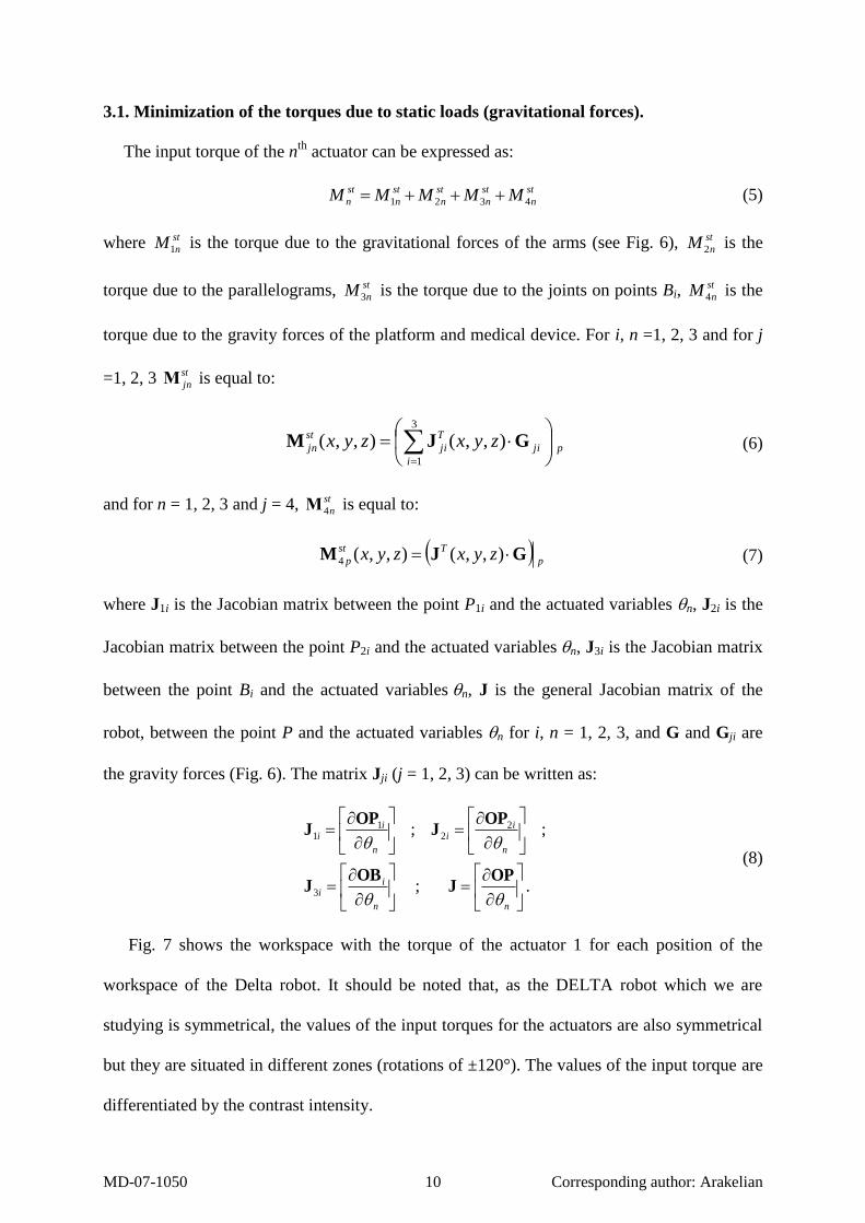
3.1. Minimization of the torques due to static loads (gravitational forces).
The input torque of the nth
actuator can be expressed as:
st
n
st
n
st
n
st
n
st
n MMMMM 4321 (5)
where st
nM1 is the torque due to the gravitational forces of the arms (see Fig. 6), st
nM 2 is the
torque due to the parallelograms, st
nM3 is the torque due to the joints on points Bi, st
nM 4 is the
torque due to the gravity forces of the platform and medical device. For i, n =1, 2, 3 and for j
=1, 2, 3 st
jnΜ is equal to:
p
i
ji
T
ji
st
jn zyxzyx
3
1
),,(),,( GJM (6)
and for n = 1, 2, 3 and j = 4, st
n4Μ is equal to:
p
Tst
p zyxzyx GJM ),,(),,(4 (7)
where J1i is the Jacobian matrix between the point P1i and the actuated variables n, J2i is the
Jacobian matrix between the point P2i and the actuated variablesn, J3i is the Jacobian matrix
between the point Bi and the actuated variablesn, J is the general Jacobian matrix of the
robot, between the point P and the actuated variables n for i, n = 1, 2, 3, and G and Gji are
the gravity forces (Fig. 6). The matrix Jji (j = 1, 2, 3) can be written as:
. ;
;;
3
22
11
nn
ii
n
ii
n
ii
OPJ
OBJ
OPJ
OPJ
(8)
Fig. 7 shows the workspace with the torque of the actuator 1 for each position of the
workspace of the Delta robot. It should be noted that, as the DELTA robot which we are
studying is symmetrical, the values of the input torques for the actuators are also symmetrical
but they are situated in different zones (rotations of ±120°). The values of the input torque are
differentiated by the contrast intensity.

MD-07-1050 11 Corresponding author: Arakelian
Fig. 6. Gravitational forces for the leg i.
The three input torques can be presented by the following expression:
FM
M
M
M
M
MT
st
st
st
st
bal
st
bal
st
bal
0
0
3
2
1
3
2
1
J (9)
where st
ibalM is the optimized torque of actuator i (i = 1, 2, 3).
The condition for the minimization of the root-mean-square (RMS) value of the torques
can be expressed as:
F
N
p i
pppippp
st
i
N
FzyxJzyxM
min
),,(),,(1
3
1
2
)3(
(10)
where st
iM is the initial torque of the actuator i, N is the number of calculated positions of the
robot, J(3i) is the ith
column of the third line of the matrix J, i = 1, 2, 3 is the number of the
actuator and xp, yp, zp are the coordinates of the pth
calculated position of the workspace.
For the minimization of the RMS value of the torques, it is necessary to minimize the sum:
N
k i
pppippp
st
i FzyxJzyxM1
3
1
2
)3( ),,(),,( (11)

MD-07-1050 12 Corresponding author: Arakelian
For this purpose, we shall achieve the condition: 0
F, from which we determine the
force:
N
k i
pppi
N
k i
pppipppi
zyxJ
zyxMzyxJ
F
1
3
1
2
)3(
1
3
1
)3(
),,(
),,(),,(
(12)
Numerical example. For the Delta robot of the SurgiScope®, the parameters are the following
(see Fig. 6):
- lAiBi=0,75 m;
- lBiCi = 0,95 m;
- m1i = 2,3 kg (mass of ith
arm with center P1i);
- m2i = 5,2 kg (mass of ith
parallelogram with center P2i);
- m3i = 3,1 kg (mass of the joint at point Bi);
- m = 79 kg (mass of the platform, joints and medical device, with center in the point P);
- lAiP1i = lAiBi/2 = 0,375 m;
- lBiP2i = lBiCi/2 = 0,475 m.
Thus the value of the added force for the given parameters is F = 931 N.
Fig. 7 shows the variations of the input torques for unbalanced and balanced Delta robot.
Thus, the reduction of the RMS value of the input torque is 99.5 %. The reduction of the
maximum value of the torque is 92%.
The purpose of this study is to develop a reliable mechanism for gravitational force
balancing of spatial parallel manipulators. Moreover, it is also tempting to consider the
minimization of the torques due to the dynamic loads, i.e. inertia forces.

MD-07-1050 13 Corresponding author: Arakelian
Fig. 7. Input torque 1 for unbalanced (left) and balanced (right) Delta robot.
3.2. Minimization of the torques due to the dynamic loads (inertia and gravitational
forces).
The input torque of the ith
actuator can be expressed as [43]:
3,2,1,3,
iA
LL
dt
dM iii
ii
dyn
i
. (13)
With the added force F, Eq. (13) can be written as:
FABMM iii
dyn
i
dyn
ibal 3,3 (14)
where [Bij] is the inverse matrix of matrix A [43] composed by the first three columns only.
We would like to point out that, in the case of the dynamic study, the input torques depend
on the velocity and acceleration of the platform displacement and it is impossible to realize an
optimization for the whole workspace of the robot (as it was for the static load minimization).
Thus we must define a trajectory in which the input torques will be minimized. The selected
trajectory is presented in Fig. 8. The kinematic characteristics of the examined motion are
given by the maximum values of the acceleration and velocity and presented in table 2
(factors «a» and «v»).
The condition for the minimization of the RMS value of the torques can be expressed as:

MD-07-1050 14 Corresponding author: Arakelian
F
N
p i
iii
dyn
i NFABM min1
3
1
2
3,3
(15)
where dyn
iM is the initial torque of the actuator i, N is the number of calculated positions of
the robot, i = 1, 2, 3 is the number of the actuator.
For the minimization of the RMS value of the torques, it is necessary to minimize the
sum:
F
N
p i
iii
dyn
i FABM min1
3
1
2
3,3
(16)
For this purpose, we shall achieve the condition: 0
F, from which we determine the
force:
N
p i
iii
N
p i
dyn
iiii
AB
MAB
F
1
3
1
2
3,3
1
3
1
3,3
(17)
For the examined trajectory with a = 1,05 m/s² and v = 0,79 m/s, we determine the external
force: F = 934 N.
Fig. 8. The output parameters for the selected trajectory.

MD-07-1050 15 Corresponding author: Arakelian
Table 2. Input torques for unbalanced and balanced robots
Maximum values of
the acceleration and
velocity
Maximum value of the input torque 1 (N.m)
Balancing force
(N)
Gain
unbalanced balanced
a =0.1m/s²
v = 0.26 m/s
645 57 956 91 %
a =1.05m/s²
v = 0.79 m/s
652 110 897 83 %
a =4.13 m/s²
v =1.57 m/s
677 326 779 49 %
Fig. 9 shows the variations of the input torque 1 for the unbalanced and balanced Delta
robots (for a = 1.05 m/s², v = 0.79 m/s, when the reduction of the input torques is 83%).
Fig. 9. Input torque 1 for unbalanced and balanced Delta robot.
4. Minimization of the input torques by a variable force applied to the platform of the
robot
This section also contains two cases: minimization of the input torques due to the static and
dynamic forces.

MD-07-1050 16 Corresponding author: Arakelian
4.1. Minimization of the torques due to the static loads (gravitational forces).
The relationship between the actuator input torques and the resultant force can be written
as:
stTres MJF (18)
where Tstststst MMM 321M .
This variable force has three components along the X, Y and Z axes. For minimization of
the input torques we use the component of Fres
along the Z axis, which is similar to the added
force F.
It should be noted that the difference in the minimized torques between the two examined
cases (with constant and variable forces) is very small (about 1%). Thus, for the minimization
of the static loads it is better to use constant force. The constant force is easier to create than
the variable force.
4.2. Minimization of the torques due to the dynamic loads (inertia and gravitational
forces).
The expressions for the input torques are similar to those in the previous case:
FABMM iii
dyn
i
dyn
ibal 3,3 (19)
The condition for the minimization of the torques at the pth
calculated position is
formulated as:
,,...,1 ,min3
1
2
3,3 NpFABMpF
i
iii
dyn
ip
(20)
where dyn
iM is the initial torque of the actuator i, N is the number of calculated positions of
the simulation, i = 1, 2, 3 is the number of the actuator.
From condition 0
p
p
F, we determine the external force for each position of the
trajectory:
MD-07-1050 17 Corresponding author: Arakelian
Np
AB
MAB
F
i
iii
i
dyn
iiii
p ,...,1 ,3
1
2
3,3
3
1
3,3
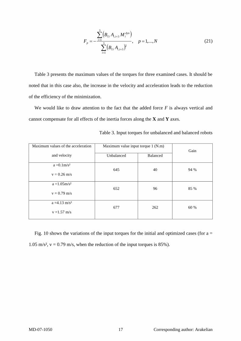
(21)
Table 3 presents the maximum values of the torques for three examined cases. It should be
noted that in this case also, the increase in the velocity and acceleration leads to the reduction
of the efficiency of the minimization.
We would like to draw attention to the fact that the added force F is always vertical and
cannot compensate for all effects of the inertia forces along the X and Y axes.
Table 3. Input torques for unbalanced and balanced robots
Maximum values of the acceleration
and velocity
Maximum value input torque 1 (N.m)
Gain
Unbalanced Balanced
a =0.1m/s²
v = 0.26 m/s
645 40 94 %
a =1.05m/s²
v = 0.79 m/s
652 96 85 %
a =4.13 m/s²
v =1.57 m/s
677 262 60 %
Fig. 10 shows the variations of the input torques for the initial and optimized cases (for a =
1.05 m/s², v = 0.79 m/s, when the reduction of the input torques is 85%).

MD-07-1050 18 Corresponding author: Arakelian
Fig. 10. Input torque 1 for unbalanced and balanced Delta robot.
It should be noted that these simulations showed that the minimization of the input torques
achieved by using a variable force is not very efficient. The difference between two examined
cases with constant and variable forces is very small. Taking into account the difficulty
involved in the practical realization of the variable force, we can conclude that for the
suggested balancing mechanism it is enough to use the constant force.
5. Increase in the positioning accuracy of spatial parallel manipulators balanced by the
suggested mechanism
It should be noted that most research papers devoted to the study of parallel manipulators
deal with the mechanical structures with rigid links. So in this case, the position of the
platform is considered to be perfectly parallel to the base and its coordinates are determined
from the nominal values of the link lengths. But in reality, the errors due to the elastic
deformations of the mechanical structure of the manipulator change the position and
orientation of the platform. Our observation showed that the increase in the platform mass
leads to increases in these errors. In this section, it will be shown that the suggested balancing
mechanism has a positive influence on the improvement of the positioning accuracy of the
parallel robot.

MD-07-1050 19 Corresponding author: Arakelian
Static rigidity of the Delta robot is defined as the 66 symmetrical matrix K that maps
generalized infinitesimal displacements Tzyxzyx ΔX of the platform
to generalized external loads Tzyxzyx MMMFFFF .
Thus, we have
XKF . (22)
Table 4. Link parameters
Link
Cross-section
area (m²)
Quadratic
moment
about y (m4)
Quadratic
moment
about z (m4)
Elastic
modulus (E)
(GPa)
Poisson
coefficient
(υ)
Links AiBi 310124.1
710913.7 710913.7 70 0.346
Parallelogram
links
410773.1 81013.2
81013.2 70 0.346
With the link parameters given in table 4 and the payload equal to 70 kg, the positioning
errors caused by the elastic deformation of the robot structure is represented in Fig. 11 (dark
gray). When the balancing force NF 931bal is applied on the platform, the relationship
(23) can be rewritten as:
balbal ΔXKFF (23)
where Fbal = [0, 0, Fbal, 0, 0, 0]T.
Fig. 11 shows the positioning errors caused by the elastic deformation of the robot
structure with balancing mechanism (light gray).
MD-07-1050 20 Corresponding author: Arakelian
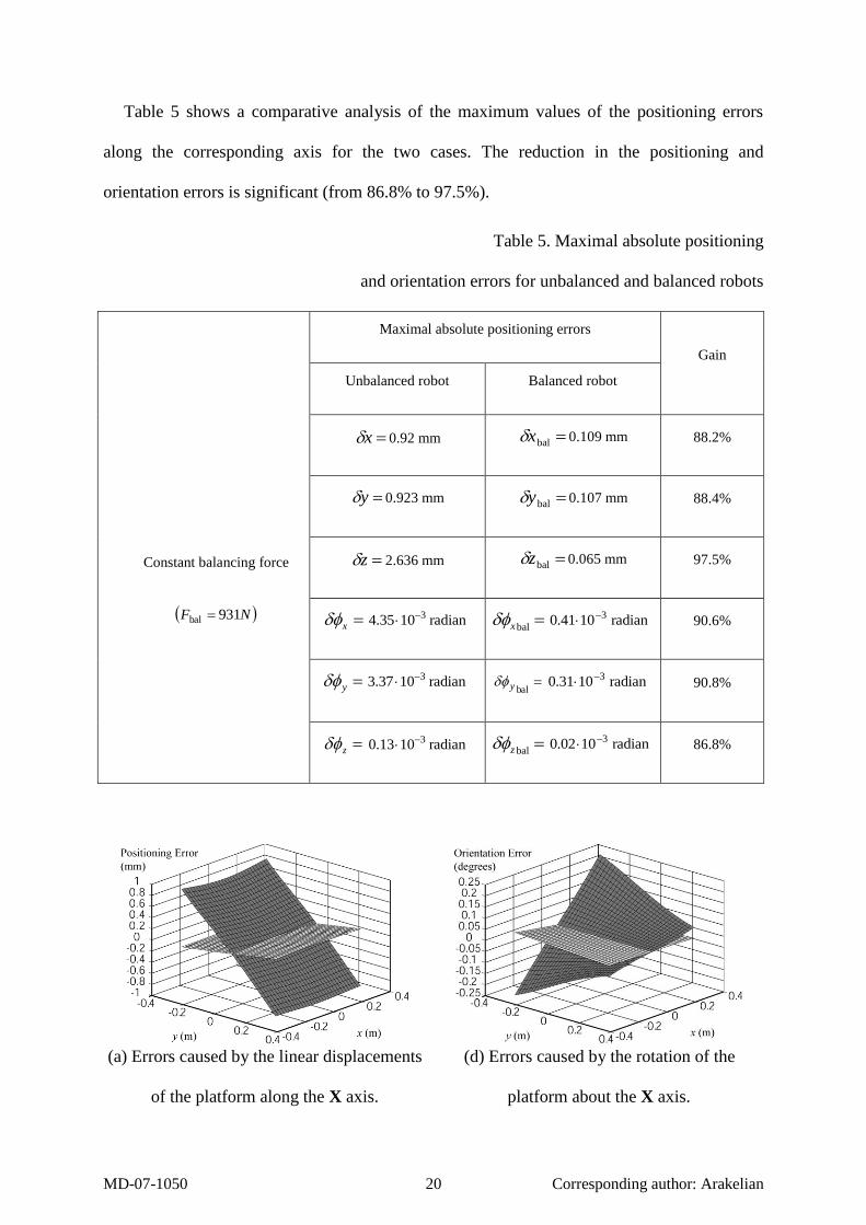
Table 5 shows a comparative analysis of the maximum values of the positioning errors
along the corresponding axis for the two cases. The reduction in the positioning and
orientation errors is significant (from 86.8% to 97.5%).
Table 5. Maximal absolute positioning
and orientation errors for unbalanced and balanced robots
Maximal absolute positioning errors
Gain
Constant balancing force
NF 931bal
Unbalanced robot Balanced robot
x 0.92 mm balx 0.109 mm 88.2%
y 0.923 mm baly 0.107 mm 88.4%
z 2.636 mm balz 0.065 mm 97.5%
x radian 1035.4 3 balx radian 1041.0 3 90.6%
y radian 1037.3 3 baly radian 1031.0 3 90.8%
z radian 1013.0 3 balz radian 1002.0 3 86.8%
(a) Errors caused by the linear displacements
of the platform along the X axis.
(d) Errors caused by the rotation of the
platform about the X axis.

MD-07-1050 21 Corresponding author: Arakelian
(b) Errors caused by the linear displacements
of the platform along the Y axis
(e) Errors caused by the rotation of the
platform about the Y axis.
(c) Errors caused by the linear displacements
of the platform along the Z axis
(f) Errors caused by the rotation of the
platform about the Z axis.
Fig. 11. Errors caused by the linear displacements and the rotation of the platform due to the
elasticity of links for unbalanced (dark gray) and balanced (light gray) Delta robot calculated
for the altitude z = -1 m.
6. Prototype and experimental validation
6.1. Prototype
A prototype has been designed and built for validation of the obtained results. It was
implemented in the structure of the Delta robot of the SurgiScope® provided by the I.S.I.S
Company. To design the prototype, the first stage is to find the optimal lengths of the
multiloop pantograph linkage taking into account that it should not collide with the legs of the

MD-07-1050 22 Corresponding author: Arakelian
Delta robot. Then the appropriate stiffness characteristics of the multiloop pantograph linkage
were found by evolution of the shapes and design concept of links, as well as by successive
optimization based on the finite element analysis.
Fig. 12. CAD model and prototype of the balancing mechanism implemented
in the structure of the Delta robot.
After assembling the prototype, its static balance was verified by placing it vertically and
noting that the mechanism is in equilibrium in any of its configurations. In such a manner, the
Mutiloop
pantograph
linkage
Base of the
Delta robot
Moving platform
Rotating
stand

MD-07-1050 23 Corresponding author: Arakelian
balancing force for developed multiloop pantograph linkage was found through
experimentation N 52APH / PANTOGRB F . The base of the balancing mechanism was then
suspended from the fixed structure of the Delta robot and its end was connected to the moving
platform (Fig. 12). In order to create a balancing force, a counterweight was used. It is
obvious that for industrial applications it is better to use pneumatic cylinders or electric
actuators with constant moment. However, the validation of the obtained results can also be
achieved by a counterweight, which develops the same force as a pneumatic cylinder or
electric actuator.
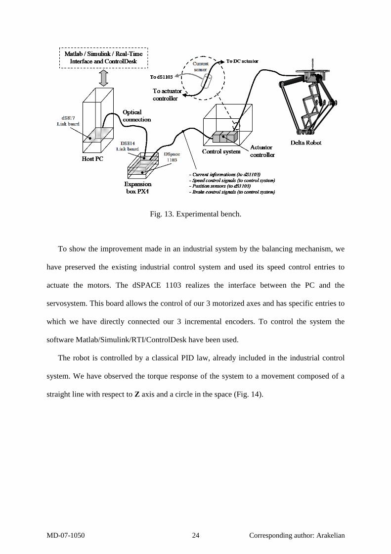
6.2. Experimental bench
The experimental bench (Fig. 13) is composed of the Delta robot with its control system, a
computer to interact with the user and a dSPACE 1103 board. The sampling period is 1 ms
(corresponding sampling frequency fe).
The Delta Robot is composed of three Parvex RX320E DC servo motors with the
following main characteristics:
- rated speed: 3000 tr/min and maximum speed: 3900 tr/min ;
- rated torque (in slow rotation) : 1.08 Nm ;
- rated current: 7.8 A and instantaneous maximum current: 20 A ;
- 100000 encoder pulses per revolution (resolution: 0.0036 degree).
MD-07-1050 24 Corresponding author: Arakelian
Fig. 13. Experimental bench.
To show the improvement made in an industrial system by the balancing mechanism, we
have preserved the existing industrial control system and used its speed control entries to
actuate the motors. The dSPACE 1103 realizes the interface between the PC and the
servosystem. This board allows the control of our 3 motorized axes and has specific entries to
which we have directly connected our 3 incremental encoders. To control the system the
software Matlab/Simulink/RTI/ControlDesk have been used.
The robot is controlled by a classical PID law, already included in the industrial control
system. We have observed the torque response of the system to a movement composed of a
straight line with respect to Z axis and a circle in the space (Fig. 14).

MD-07-1050 25 Corresponding author: Arakelian
Fig. 14. Selected trajectory for experimental validation of torque minimization.
6.3. Experimental results and comparative analysis
The input torques measured for each actuator in different cases are denoted by A, B, C and
D:
A. unloaded robot;
B. loaded robot (robot with the load of 690 N);
C. load balanced robot (balancing by mechanism with force of 690 N);
D. load and mechanical system balanced robot (balancing by mechanism with force of
880 N).
We would like to draw attention to cases C and D. In case C, we have only compensated
the load added on the robot platform, to obtain the same result as thus obtained when the
robot is unloaded. In case D, we have taken into account the mass of the Delta Robot links,
which gives the best result.
The measured input torques have been taken for two different speeds of the movement
(maximal cartesian acceleration and maximal cartesian speed):
Experiment 1 (E1): 15% of the maximum capacity of the robot to neglect most of the
dynamic effects (we consider it as the static mode of operation).
Experiment 2 (E2): 100% of the maximum capacity of the robot to observe the
improvement for dynamic mode of operation.

MD-07-1050 26 Corresponding author: Arakelian
(1a) Input torque 1 (case E1) (1b) Input torque 1 (case E2)
(2a) Input torque 2 (case E1) (2b) Input torque 2 (case E2)
(3a) Input torque 3 (case E1) (3b) Input torque 3 (case E2)
Fig. 15. Experimental measures of input torques for three actuators of the Delta robot.
The obtained measurements confirm perfectly the theoretical results (Fig. 15):
- When balancing is carried out by taking into account only the load on the platform, the
results are similar to those obtained for the unloaded robot (cases A and C).

MD-07-1050 27 Corresponding author: Arakelian
- When balancing is carried out by taking into account the load on the platform and loads
of robot links, we obtain the lowest values for the input torques (cases D).
Tables 6 and 7 show the reduction of the input torques for experiments 1 (E1) and 2 (E2).
Table 6. Input torques (E1: static mode of operation)
A B C D
Improvement gain 3 (%)
C D
Maximum
values of the
measured
torques (Nm)
Actuator 1 306 882 324 199 63 77
Actuator 2 217 653 208 145 68 77
Actuator 3 211 449 221 180 50 59
Table 7. Input torques (E2: dynamic mode of operation)
A B C D
Improvement gain 3 (%)
C D
Maximum
values of the
measured
torques (Nm)
Actuator 1 456 880 502 423 43 52
Actuator 2 291 608 342 264 44 56
Actuator 3 313 400 320 328 20 18
We can observe that improvement for actuators 1 and 2 in the quasi static movement is
77% and for actuator 3 is 59%. For the dynamic mode of operation the improvement for
actuator 1 is 52%, for actuator 2 is 56% and for actuator 3 is 18%.
3 This gain represents in percent the reduction of the torques compared to (-) case B.

MD-07-1050 28 Corresponding author: Arakelian
Gains for actuator 3 are quite different from the two others, because this one was less
solicited by the given trajectory than the two others, i.e. for the given trajectory the load of the
platform on actuator 3 was smaller (see Table 7, case B). So, it is natural that for this actuator
we do not observe consequent improvement of its torque by the balancing mechanism.
The experimental validation of the suggested balancing approach showed that satisfactory
results are achieved and the developed system is fully operational.
Table 8. Trajectory for experimental validation of the positioning accuracy improvement.
Points x (mm) y (mm) z (mm)
1 400.0 0.0 -900.0
2 325.5 41.7 -949.9
3 249.9 84.4 -1000.2
4 175.6 127.5 -1050.0
5 100.3 169.9 -1100.1
6 25.5 212.4 -1149.8
7 -49.9 255.4 -1199.7
8 -124.8 298.3 -1249.6
9 -200.8 340.7 -1299.8
The next step of the experimental validation is the estimation of the positioning errors for
balanced and unbalanced robots. For this purpose a trajectory given by the following 9 points
was chosen (table 8).
These points are uniformly distributed about a straight line of 800 mm length. To obtain
this line physically, a sphere is used, which was moved along a rail (Fig. 16). The position of
each point is measured by three dial gauges, which determine the center of the sphere. The

MD-07-1050 29 Corresponding author: Arakelian
purpose of these measurements is to obtain the positioning errors for unbalanced and balanced
Delta robots.
Fig. 16. Measuring of the positioning errors for given straight line trajectory.
The obtained results are shown in Fig. 17. The abscissa axis corresponds to the unloaded
case. Then the Delta robot was loaded and the relative errors were measured (graph
“unbalanced robot”). Finally the robot was balanced by the suggested mechanism and relative
errors are shown for the “balanced robot”. The average rate of the improvement in the relative
positioning accuracy with respect to Z axis is 93.5%, which corresponds to the value obtained
by the numerical simulations.
Fig. 17. Relative positioning errors with respect to z axis
for unbalanced and balanced robots.

MD-07-1050 30 Corresponding author: Arakelian
With regard to the measurement of other positioning and orientation errors, caused by the
displacement of the platform, we observed that the frame of the robot is insufficiently rigid in
a cross-section direction. Taking into account the important mass of the counterweight, it is
strongly deformed and leads to significant distortions of the measured parameters.
7. Conclusion
In this paper, a new approach for balancing of spatial parallel manipulators has been
presented. It involves connecting a secondary mechanical system to the initial robot, which
generates a vertical force applied to the platform of the manipulator. The suggested balancing
mechanism is designed on the base of the multiloop pantograph linkage introduced between
the robot base and the platform. The minimization of the input torques was carried out by
constant and variable forces for static and dynamic modes of operation. It was shown that a
significant reduction in input torques can be achieved by the suggested balancing mechanism:
the reduction of the root-mean-square value of the input torque due to the gravitational forces
is 99.5% and the maximum value is 92%. The positioning errors of the unbalanced and
balanced parallel manipulators are provided. It was shown that the elastic deformations of the
manipulator structure due to the payload, change the altitude and the inclination of the
platform. A significant reduction in these errors is achieved by using the balancing
mechanism (from 86.8% to 97.5%). The theoretical results obtained by numerical simulations
were confirmed by experimental study carried out by means of the developed prototype
mounted on the Delta robot.
It should be noted that the suggested balancing mechanism not only improves the
positioning accuracy of the parallel robot, but also sharply reduces stress in its links and
efforts in the joints. This system can also be used for operational safety of robotized medical
MD-07-1050 31 Corresponding author: Arakelian
devices because it can maintain the fixed position of the platform if the parallel robot
actuators should accidentally stop.
The suggested balancing approach was demonstrated for the Delta robot but the designed
mechanism can be applied to many spatial parallel robots with 3 to 6 degrees of freedom. This
type of mechanism is expected to lead to designs that can carry a larger payload and/or reduce
energy consumption.
Finally, it should be noted that the proposed balancing mechanism has been patented [44]
and additional information is available upon request.
Acknowledgments
The authors would like to thank the «Intelligent Surgical Instruments and Systems»
Company for its financial support and Professor Jean Le Flecher for the advice during
development of the prototype.
References
[1] Lowen G. G., Tepper F. R., Berkof R. S., 1983, “Balancing of Linkages – Update”.
Mechanism and Machine Theory, Vol. 18 (3), pp.213-230.
[2] Arakelian, V. and Smith, M.R., 2005, “Shaking force and shaking moment balancing of
mechanisms: an historical review with new examples,” J. Mech. Design Trans. ASME,
Vol. 127, March, pp. 334-339 (see also ERRATUM, Vol. 127, September 2005, pp.
1034-1035) (2005).
[3] Agrawal, S.K. and Fattah, A., 2004, “Reactionless space and ground robots: novel
designs and concept studies,” Mechanism and Machine Theory, Vol. 39, pp. 25-40.
[4] Wang, J. and Gosselin, C.M., 1999, “Static balancing of spatial three-degree-of-freedom
parallel mechanisms,” Mechanism and Machine Theory, Vol. 34, pp. 437-452.

MD-07-1050 32 Corresponding author: Arakelian
[5] Newman, W.S. and Hogan, N., 1986, “The optimal control of balanced manipulators,”
Proc. winter annual meeting of the ASME, Anaheim, California.
[6] Laliberté, T., Gosselin, C.M. and Jean, M., 1999, “Static balancing of 3-DOF planar
parallel mechanisms,” IEEE/ASME Transactions on Mechatronics, Vol. 4, No. 4,
December, pp. 363-377.
[7] Fujikoshi, K., 1976, “Balancing apparatus for jointed robot,” Patent JP51-122254,
October 26.
[8] Arakelian, V., 1989, “Manipulator”, Patent SU 1465298, March 15.
[9] Wang, J. and Gosselin, C.M., 2000, “Static balancing of spatial four-degree-of-freedom
parallel mechanisms,” Mechanism and Machine Theory, Vol. 35, pp. 563-592.
[10] Russo, A., Sinatra, R. and Xi, F., 2005, “Static balancing of parallel robots,”
Mechanism and Machine Theory, Vol. 40, pp. 191-202.
[11] Lakota, N.A. and Petrov, L.N., 1985, “Manipulators for assembly tasks.” In the book
“Automation of assembly tasks”, Moscow, pp.137-153.
[12] Ebert-Uphoff, I., Gosselin, C.M. and Laliberté, T., 2000, “Static balancing of spatial
parallel mechanisms – Revisited.” J. Mech. Design Trans. ASME, Vol. 122, pp. 43-51.
[13] Herder, J.L., 2001, “Energy-free systems. Theory, conception and design of statically
balanced mechanisms”, Ph.D. thesis, Delf University of Technology.
[14] Streit, D.A. and Shin, E., 1993, “Equilibrators for planar linkages,” J. Mech. Design
Trans. ASME, Vol. 115, pp. 604-611.
[15] Vrijlandt, N. and Herder, J.L., 2002, “Seating unit for supporting a body or part of a
body”, Patent NL1018178, December 3.
[16] Vladov, I.L., Danilevskij, V.N. and Rassadkin, V.D., 1981, “Module of linear motion of
industrial robot”, Patent SU 848350, July 23.
MD-07-1050 33 Corresponding author: Arakelian
[17] Ebert-Uphoff, I. and Johnson, K., 2002, “Practical considerations for the static
balancing of mechanisms of parallel architecture”, Journal of Multi-body Dynamics,
Vol. 216, Part K, pp.73-85.
[18] Tuda, G. and Mizuguchi, O., 1983, “Arm with gravity-balancing function”, Patent
US4383455, May 17.
[19] Herder, J.L., 2002, “Some considerations regarding statically balanced parallel
mechanisms,” Proc. WORKSHOP on Fundamental Issues and Future Research
Directions for Parallel Mechanisms and Manipulators”, Quebec City, Quebec, Canada,
October 3-4.
[20] Leblond, M. and Gosselin, C.M., 1998, “Static balancing of spatial and planar parallel
manipulators with prismatic actuators”, Proc. DETC’98, Atlanta, Georgia , USA , pp.1-
12.
[21] Popov, M. and Tyurin, V., 1988, “Balanced manipulator”, Patent SU 1379105, March 7.
[22] Agrawal, A. and Agrawal, S.K., 2005, “Design of gravity balancing leg orthosis using
non-zero free length springs,” Mechanism and Machine Theory, Vol. 40, pp. 693-709.
[23] Simionescu, I. and Ciupitu, L., 2000, “The static balancing of the industrial arms. Part I:
Discrete balancing”, Mechanism and Machine Theory, Vol. 35, pp. 1287-1298.
[24] Segla, S, Kalker-Kalkman, C.M. and Schwab, A.L., 1998, “Statical balancing of a robot
mechanism with the aid of a genetic algorithm,” Mechanism and Machine Theory, Vol.
33, No. 2, pp. 163-174.
[25] Minotti, P. and Pracht, P., 1988, “Ressort et mécanismes : une solution aux problèmes
d’équilibrage”, Mechanism and Machine Theory, Vol. 23, pp. 157-168.
[26] Dzhavakhyan, R.P. and Dzhavakhyan, N.P., 1989, “Balanced manipulator”, Patent
SU1521579, November 15.
[27] Hervé, J., 1985, “Device for counter-balancing the forces due to gravity in a robot arm”,
Patent FR2565153, June 12.

MD-07-1050 34 Corresponding author: Arakelian
[28] Bartlett, D.S., Freed, D.I. and Poynter, W.H., 1988, “Robot with spring pivot balancing
mechanism”, Patent US4753128, June 28.
[29] Popov, M.V., Tyurin, V.N. and Druyanov, B.A., 1984, “Counterbalanced manipulator”
Patent SU1065186, January 7.
[30] Simionescu, I. and Ciupitu, L., 2000, “The static balancing of the industrial arms. Part I:
Continuos balancing”, Mechanism and Machine Theory, Vol. 35, pp. 1299-1311.
[31] Lakota, N.A. and Petrov, L.N., 1985, “Manipulators for assembly tasks.” In the book
“Automation of assembly tasks”, Moscow, pp.137-153.
[32] Kondrin, A.T., Petrov, L.N. and Polishchuk, N.F., 1990, “Pivoted arm balancing
mechanism” Patent SU1596154, September 30.
[33] Petrov, L.N. and Polishchuk, N.F., 1979, “Vertical displacement device”, Patent
SU643323, January 25.
[34] Popov, M.V. and Tyurin, V.N., 1983, “Balanced manipulator”, Patent SU1000271,
February 28.
[35] Gvozdev, Y.F., 1992, “Manipulator”, Patent SU1777993, October 30.
[36] Gvozdev, Y.F., 1990, “Manipulator”, Patent SU1537512, January 23.
[37] Gvozdev, Y.F., 1987, “Manipulator”, Patent SU1308463, May 7.
[38] Belyanin, P.N., 1988, “Balanced manipulators,” Mashinostroynie, Moscow, 263p.
[39] Wildenberg, F., 2002, “Compensating System for a Hexapod”, Patent US6474915,
November 5.
[40] Dzhavakhyan, R.P. and Dzhavakhyan, N.P., 1987, “Balanced manipulator”, Patent
SU1357218, December 7.
[41] Segawa, Y., Yamamoto, M. and Shimada, A., 2000, “Parallel Link Mechanism”, Patent
JP2000120824, April 28.
[42] Clavel, R., 1990, “Device for movement and displacing of an element in space,” Patent
US4976582, December 11.

MD-07-1050 35 Corresponding author: Arakelian
[43] Miller, K. and Clavel, R., 1992, “The Lagrange-based model of Delta-4 robot
dynamics,” Robotersysteme, Vol. 8, pp.49-54.
[44] Baradat, C., Arakelian, V. and Maurine, P., 2006, “Parallel robot including of load-
compensation system,” Patent FR2880575, July 14.

MD-07-1050 36 Corresponding author: Arakelian
List of figures
Fig. 1. A Delta robot used in the SurgiScope®, a
robotized navigation tool-holder designed for
neurosurgery and developed by the ISIS company.
Fig. 2. Principle of balancing.
Fig. 3. Simplified scheme of the balancing mechanism.
Fig. 4. Delta robot with the balancing mechanism.
Fig. 5. Stewart platform with implemented balancing system.
Fig. 6. Gravitational forces for the leg i.
Fig. 7. Input torque 1 for unbalanced (left) and balanced (right) Delta robot.
Fig. 8. The output parameters for the selected trajectory.
Fig. 9. Input torque 1 for unbalanced and balanced Delta robot.
Fig. 10. Input torque 1 for unbalanced and balanced Delta robot.
Fig. 11. Errors caused by the linear displacements and the rotation of the platform due to the
elasticity of links for unbalanced (dark gray) and balanced (light gray) Delta robot calculated
for the altitude z = -1 m.
Fig. 12. CAD model and prototype of the balancing mechanism implemented in the structure
of the Delta robot.
Fig. 13. Experimental bench.
Fig. 14. Selected trajectory for experimental validation of torque minimization.
Fig. 15. Experimental measures of input torques for three actuators of the Delta robot.
Fig. 16. Measuring of the positioning errors for given straight line trajectory.
Fig. 17. Relative positioning errors with respect to z axis for unbalanced and balanced robots.

MD-07-1050 37 Corresponding author: Arakelian
List of tables
Table 1. Balancing schemes for robotic systems
Table 2. Input torques for unbalanced and balanced robots
Table 3. Input torques for unbalanced and balanced robots
Table 4. Link parameters
Table 5. Maximal absolute positioning and orientation errors for unbalanced and balanced
robots
Table 6. Input torques (E1: static mode of operation)
Table 7. Input torques (E2: dynamic mode of operation)
Table 8. Trajectory for experimental validation of the positioning accuracy improvement.