design and prototype of a personal ascending device based
TRANSCRIPT

Design and Prototype of a Personal Ascending Device Based onthe Principle of a Capstan Winch
byDaniel P. Gillund
Submitted to the Department of Mechanical Engineering inPartial Fulfillment of the Requirements for the Degree of
Bachelor of Science in Mechanical Engineeringat the
Massachusetts Institute of Technology
June 2014
Copyright 2014 Daniel P. Gillund. All rights reserved.
The author hereby grants to M.I.T. permission to reproduceand to distribute publicly paper and electronic copies of this
thesis document in whole or in part in any medium nowknown or hereafter created
Signature of Author:
MASSACHUSETTS INSTITUTEOF TECNRLOGY
JUL 3 02014
1I J A RI E S
Signature redactedDepartment of Mechanical Engineering
May 9, 2014
Certified by: Signature redactedSanjay E. Sarma
Professor of Mechanical Engineering
Signature redacted Thesis Supervisor
Accepted by:
Anette HosoiProfessor of Mechanical Engineering
Undergraduate Officer

Design and Prototype of a Personal Ascending Device Based on the Principle of aCapstan Winch
byDaniel P. Gillund
Submitted to the Department of Mechanical Engineering on May 9,2014 in PartialFulfillment of the Requirements for the Degree of Bachelor of Science in Mechanical
Engineering
Abstract
The consumer market currently offers no options for a low-cost, personalascending device. The purpose of this project is to propose a powered ascender, actuatedby common power tool components and operating on the principle of a capstan winch, asa candidate to fill that void. The first objective was to design and construct a workingprototype. The second was to explore the feasibility of manufacturing a low costconsumer version of the product. Safety, functionality, and cost drove the design process.
The ascender was designed and built around the motor and gearbox from aDewalt 36v hammerdrill. Individual components were machined in undergraduatemachine shops on the MIT campus and in the MIT Hobby Shop.
Testing of the ascender was carried out using standard gym equipment andweights. The completed unit can lift 100 kg at 0.4 meters per second with an overallefficiency of 8.5%. This result was 57% lower than the predicted speed of 0.7 meters persecond with an expected 14.7% efficiency. Analysis revealed a design flaw which canaccount for most of the discrepancy in the predicted and observed performance andwhich can easily be remedied.
Powered ascenders within the same speed and load range are sold for severalthousand dollars, demonstrating the feasibility of a low cost powered ascender as a viableproduct.
Thesis Supervisor: Sanjay E. SarmaTitle: Professor of Mechanical Engineering
3

Acknowledgements
I would like to thank all the shop guys at the LMP machine shop, the Papallardoundergraduate machine shop, and the Hobby Shop; especially Jerry from LMP and Jimfrom Papallardo for their advice and help in fabricating the prototype.
Prof. Sanjay Sarma for sponsoring my thesis project and Stephen Ho for his help andadvice.
My roommate, Joseph, for lending a hand whenever I asked and for reminding me onnumerous occasions to work on my thesis.
My fiancde, Nicolette, for assisting me in running tests and for recording video of thesame.
Dylan and Josh for answering various questions and offering their assistance multipletimes.
Numerous friends who so graciously and selflessly volunteered to test my device onvarious buildings around campus (all of which I dutifully declined).
4

Table of Contents
i. Table of Figures................................................................................................... 6
1. Introduction:.............................................................................................................. 71.1 Impetus for Project..........................................................................................................71.2 Why a Capstan Winch?........................................71.3 Pre-alpha Prototype..................................................................................................... 8
2. Relevant Products: ........................................................................ 82.1 Electric Powered Ascenders.........................................................................................82.2 Gas Powered Capstan W inch Ascenders .................................................................... 92.3 High-Torque Cordless Power Tools ............................................................................ 9
3. Governing Principles...........................................93.1 Capstans .......................................................................................................................... 93.2 DC M otors.....................................................................................................................113.3 Planetary Gears ......................................................................................................... 12
4. Design Process: .............................................. 134.1 Functional Requirements .......................................................................................... 134.2 Safety Considerations ............................................................................................... 144.3 Time and Resource Considerations.......................................................................... 144.4 M otor and Gearbox.................................................................................................. 154.5 Structure.......................................................................................................................174.6 Battery and Switching.............................................................................................. 204.7 Harnessing.....................................................................................................................23
5. Building the Prototype:.............................................235.1 M anufacturing M ethods........................................................................................... 255.2 Difficulties during Build ........................................................................................... 26
6. Mathematical Models of the Ascender............... ................. 276.1 Generating a Load-Speed Curve.............................................................................. 276.2 Capstan M odel ......................................................................................................... 29
7. Testing and Results .................................................................................................. 297.1 Testing the Ascender.....................................................................................................29
7.3 Results ................................................................................................................ 317.4 Problems and Suggested Solutions........................................................ 327.5 Discussion..................................................................................................................... 35
8. Conclusion ... ......................................... 38.1 Feasibility......................................................................................................................368.2 Design Changes for M ass Production....................................................................... 368.3 Future W ork .............................................................................................................. 39
9. Works Cited.................................................40
5

Table of Figures & Tables
Figure 1: C apstan......................................................................................................... 10
Figure 2. Torque Speed Curve of a DC Motor........................................................ 11
Figure 3. Planetary Gears ......................................................................................... 13
Table 1. Project Expenses.......................................................................................... 15
Figure 4. Dewalt Motor .............................................................................................. 16
Figure 5. Dewalt Gearbox .......................................................................................... 16
Figure 6. Torque-Speed Curve of 36v Dewalt Motor .............................................. 16
Figure 7. Gearbox and Motor Rings ......................................................................... 17
Figure 8. Structural Beams ....................................................................................... 18
Figure 9. Drive Shaft and Outer Bearing Holder ..................................................... 18
Figure 10. Capstan Pulley ......................................................................................... 19
Figure 11. Pulley Cover ............................................................................................... 20
Figure 12. Rope Wound around Capstan Pulley ..................................................... 20
Figure 13. Ascender with Electronics....................................................................... 22
Figure 14. Ascender Circuit Diagram...................................................................... 22
Figure 15. Ascender Harness ..................................................................................... 23
Figures 16. Complete Ascender - Exploded View ............................ 24
Table 2. Manufacturing Methods by Component................................................... 25
Figures 17. Completed Ascending Unit with Cover On .......................................... 26
Figure 18. Completed Ascending Unit with Cover Off ........................................... 27
Figure 19. Modeled Load-Speed Curve .................................................................... 28
Figure 20. Testing Setup............................................................................................ 30
Table 3. Measured and Predicted Ascent Speeds ........................... 31
Figure 21. Ascender Load-Speed Curve ................................. 32
Figure 22. Current Pulley Cover and Proposed Pulley Cover Interact with Rope.. 34
Figure 23. Current Configuration of Capstan Pulley and Planetary Gears ......... 36
Figure 24. Improved Configuration of Capstan Pulley and Planetary Gears ..... 37
6

1. Introduction:
Personal ascenders were once found only on Batman's utility belt. However, in the
last decade several companies have begun producing and selling ascending devices.
Some of these ascenders are targeted at large corporate or military clients. Others are
targeted towards foresters or hunters. All of them are priced at $2,500 or more. This price
range is outside the reach of small companies, amateur groups, and individuals who could
use such a device for business, research, or recreation.
1.1 Impetus for Project
Although ascending devices are currently sold for thousands of dollars, cordless
power tools with similar power requirements are sold for five hundred dollars or less. By
emulating the cost efficient design and manufacturing strategies used by power tool
companies, it may be possible to produce and sell a personal ascender at a fraction of the
price currently offered for ascenders.
1.2 Why a Capstan Winch?
Capstan winches have been used on sailing vessels for hundreds of years. They are
simple, low cost, and reliable. Capstan winches first appeared in their modem,
electronically driven form in the nautical industries in the early 1950s. Since then they
have been adopted for a variety of other uses such as logging and towing.
Capstans hold several advantages over other forms of winches, many stemming from
the fact that the cable is not stored on the pulley as it is spooled:
* Unlimited lengths can be pulled through the winch
e The winch can be started at any point along a line, provided there is sufficient
slack in the line
* Capstans do not speed up or lose pulling force from the cable building up
upon itself; the speed and pulling force are constant
* Capstans can use thicker lines, including rope, which is more versatile than
steel cable
7
* Slack can be taken up and reverse motion easily controlled with the capstan
pulley complete stationary relative to the winch (unpowered)
However there are two disadvantages of the capstan winch for this application that
must be overcome with proper engineering and thoughtful design:
* Powered decent is not easily accomplished
* Tension must be maintained at all times in the downward line.
1.3 Pre-alpha Prototype
In the fall of 2012, I built a prototype of a compact personal ascender as an
independent experiment. Only the roughest calculations were carried out before
construction and the device was made with extremely low-cost components. Using an
eight-dollar motor with an overall length of less than 8 inches, this pre-alpha prototype
was able to lift a 100 kg load several inches off the ground. Although the motor burned
out when line bunched up on the pulley, the concept of a cheap, powerful, electric
ascender was shown to be viable. Further reflection on the result of this experiment and
its implications led me to consider designing and building a much more serious prototype
as my senior thesis.
2. Relevant Products:
This project encompasses the intersection of three existing product groups: electric
powered ascenders, gas powered capstan winch ascenders, and high-torque cordless
power tools.
2.1 Electric Powered Ascenders
Portable, electronic powered ascenders such as the Atlas ascenders, the ACC Power
Ascender by ActSafe, and the PowerQuick Ascender are targeted primarily at military,
government, and corporate clients. These products are bulky, prohibitively expensive,
and are difficult to purchase for individuals or small groups. These ascenders use
8

complicated, proprietary winch designs rather than simple capstan pulleys to provide
traction when ascending a rope. According to the specifications posted on their respective
websites, the ActSafe ACC II can ascend at 0.37 m/s, the PowerQuick PQ500-1 at 0.22
m/s, and the Atlas APA-3 at 1.52 m/s.
2.2 Gas Powered Capstan Winch Ascenders
Gas powered capstan ascending units such as the SP-CW by Simpson Winch Inc. and
the Wraptor Gas-Powered Ascender by Ropetek are targeted primarily to foresters and
hunters. They have slow speeds, low weight limits, loud engines, and cost roughly
$2,500. Both of these ascenders use simple capstan pulleys to provide traction when
climbing a rope. According to the specifications posted on their respective websites, the
Simpson CS-CW can ascend at 0.21 m/s and the Ropetek Wraptor at 0.51 m/s.
2.3 High-Torque Cordless Power Tools
Recent advances in battery technology have led to the production and sale of high-
torque power tools using lithium based batteries such as 36v Dewalt hammer drills. Many
of these power tools have a power output which is well within the range of the power
required to lift an average person at 1 m/s. Some of the tools in this category can be
purchased for only $500. For example, the Dewalt DC901KL 36 v 2" Hammerdrill can
be purchased with a carrying case, two battery packs and a charger from for $499. The
DC901 is a product with a strikingly similar list of major components to an electric
ascender, and is in fact more complex. This suggests that producing a $500 personal
ascender might be a feasible undertaking.
3. Governing Principles
3.1 Capstans
A capstan in its simplest form is a cylinder around which a rope or other form of
flexible line is wrapped. Due to the friction between the rope and the cylinder a decrease
in the tension between the two ends of the rope is observed. This effect follows a trend
9

that to first order does not depend on the rope size, capstan size, or amount of tension. As
shown in Equation 2.1 (Johnson, Contact Mechanics, pg. 245), the ratio of the two
tensions depends only on the coefficient of friction at the interface between rope and
capstan (p) and the angle through which the rope contacts the surface of the capstan,
known as the wrap angle (0). A diagram of a rope and capstan can be seen in Figure 1.
= e O [2.1]T2
T2
Figure 1. Capstan
Rotating the capstan in such a situation will generate a difference in tension across the
two sides of the line which maintains the ratio from Equation 2.1. Flat and round belt
drives are able to transmit power because of this effect. A winch can pull large loads with
very little tension on the other side of the line by using a wrap angle of several complete
rotations. For example, the force needed to hold 500 lbs with hemp rope wrapped twice
around a wooden capstan (g = 0.5) is:
T =T[2.2]
10

500 lbseo-5x40 = 0.934 lbs [2.3]
Less than one pound of force is required to support 500 pounds. This result may
not be intuitively obvious; however it is a very important one when considering using a
capstan winch as an ascender. Such a large ratio between the load tension and the
downward tension indicates that weight of many commonplace items (such as a
backpack) will provide sufficient tension for the ascender to hoist a person up the rope.
3.2 DC Motors
Direct current electric motors are transducers which use strong magnetic fields to
convert electricity into mechanical power in the form of continuous mechanical rotation.
Motors are often specified by their stall torque and no load speed. Most brushed DC
motors follow a linear trend between these two points. This line is referred to as the
torque speed curve. The slope of the line is the motor constant, Km. An example torque
speed curve can be seen in Figure 2. Power transmitted by the motor is equal to the
torque times the angular velocity of the output shaft, as seen in Equation 3.4. In other
words, power is equal to the rectangular area under the operating point.
Stall Torque
Max Power
Load Rating
Max Efficiency
No Load Speed
Speed
Figure 2. Torque Speed Curve of a DC Motor
11

[3.4]
Besides the stall torque and the no load speed, there are three other notable points
along the torque speed curve. The operating point with the most power output occurs at
half the stall torque, which is also half of the no load speed. Maximum power is generally
not safe for continuous operation because of the amount of heat which must be
dissipated. However, machines are commonly designed to operate at this point for short
durations under heavy use. Somewhere between the max power and no load conditions
lies the load rating. The load rating is the highest power output at which it is safe to run
the motor continuously. The point at which the motor operates with maximum efficiency
also lies in this range. The mechanical power output of the motor at this point is closer
(percentage-wise) to the electrical input power than at any other point along the curve.
For economical reasons, it is typically considered the best place to run a motor
continuously.
Considering these characteristics of DC motors, a well-designed personal ascender
would be operating at a point near to maximum efficiency when carrying a payload
equivalent to the average sized potential user. The maximum rated payload capacity
could be set either be at the load rating or closer to the max power point, depending on
how long the motor and its mount can safely operate in that range.
3.3 Planetary Gears
Planetary gear drives are gear trains in which one central (sun) gear engages with
multiple (planet) gears which orbit around the sun gear, as shown in Figure 3. They are
capable of transmitting much more torque for a given gear size than a conventional gear
train because many more teeth are being engaged. Planetary gears normally are arranged
such that the shaft driving them is concentric with the output shaft. Placing gearing in line
with the motor results in more compact and conveniently shaped drives.
12

Ring Gear Planet Gear
Sun Gear - Planet Carrier
Figure 3. Planetary Gears
Personal ascenders require high torque power transmission and a very compact
footprint, making planetary gearing an excellent option.
4. Design Process:
The purpose of this prototype is to offer a solution to fill a very specific, well defined
user need; a low-cost personal ascending device. As a result, the design process is
somewhat simplified. Functional requirements can be identified on the basis of that need
and the design driven by aiming for those requirements.
4.1 Functional Requirements
In order to fill the need for a personal ascender, the device needs to accomplish the
purpose of lifting a person up a rope at a reasonable pace and it must do so safely and
reliably. Based on the capabilities of competing products, it should be able to lift 100 kg
at 0.5 m/s. The ascender should be stable when stopped partway up a rope, even if the
battery has died and should provide a means of safe and expedient decent. It should be
13
comfortable to carry in a backpack. In other words it should have a total mass of 10
kilograms or less and have a volume of 5 Liters or less. The device must allow spooling
to begin in the middle as well as the end of a rope. The entire product should be
engineered to last at least 1,000 hours of use with 99.9% reliability; however, since it will
be supporting people high above the ground, all the structural components should be
designed for infinite life with generous safety factors.
4.2 Safety Considerations
When designing a device to move people, especially vertically, safety is of the utmost
importance. Although the alpha-prototype is only intended to lift 250 lbs, every link in
the load-bearing structure of the device was designed to hold a load of at least 650 lbs.
This gives a safety factor of 2.6 for the maximum recommended load. To prevent the
motor from burning out or the battery from discharging too quickly and rupturing, a
thermal overload protection breaker was included in the design. As an additional safety
feature, a fall arrestor used in series with the ascender would prevent the user from falling
if the ascender were to fail.
4.3 Time and Resource Considerations
The design of the alpha-prototype was affected to some extent by limits on the
available time and resources. The most expensive components which had to be acquired
to build an ascender were the motor, gearbox, and battery. A large capacity 37v lithium
polymer battery was available to repurpose for the project, thus narrowing choices for
motors down to those that run at 36 v.
The duration of the entire project was only three months. This was a very tight
timescale for such an ambitious project and as a result compromises in aesthetics and
some non-essential functionality had to be made in order to produce and test a working
prototype on schedule.
The breakdown of expenses for building the alpha-prototype can be seen below in
Table 1.
14

Description Price150 A Circuit Breaker $ 53.90Bearings $ 35.80Relay $ 41.65Electrical Components $ 41.97Structural Components $ 104.66Harness Components $ 95.76Battery RepurposedMotor $ 78.99Gearbox $ 69.99Water jet cost $ 80.00Total $ 602.72
Table 1. Project Expenses
Including the price of a battery (approximately $150), the alpha-prototype was built at
a cost of $750. Although this is higher than the target selling price of the end product, it
is a point of interest that the cost of building a single unit was less than a third of the
selling price of any of the other ascenders currently available. It is important to keep in
mind that the components for this project were all purchased in small quantities at retail
prices. The cost per unit of mass producing the exact same design would be a fraction of
the cost of making one unit. There are also many changes which could be made to the
design which would decrease the cost of manufacturing, some of which are discussed in
section 8.2.
4.4 Motor and Gearbox
For the purposes of this project, it was necessary to consider motor and gear train
options available quickly and at low cost. The motor and gearbox from a Dewalt 36v
hammerdrill were the most cost-effective option capable of providing the torque and
power required for the ascender. The motor and gearbox are pictured in Figures 4. and 5.
15

Figure 4. Dewalt Motor Figure 5. Dewalt Gearbox
The Dewalt motor is rated at 300 amps stall current and 15,600 rpm no load speed,
with a torque constant of 0.0184 Nm/amp. The stall torque can be calculated as 5.51 Nm.
The expected torque-speed curve with max power and max continuous load can be seen
in Figure 6.
Figure 6. Torque-Speed Curve of 36v Dewalt Motor
The gearbox has three speeds; however, only the lowest, 400 rpm, will be used in the
ascender. The max power output of the motor/gearbox combination is listed as 750 watts.
(Dewalt, "Owner's Manual")
16
6 Dewalt Motor Torque-Speed Curve5.51
4
:r 2.75
[ -
0.510
0 7800 15600
RPM
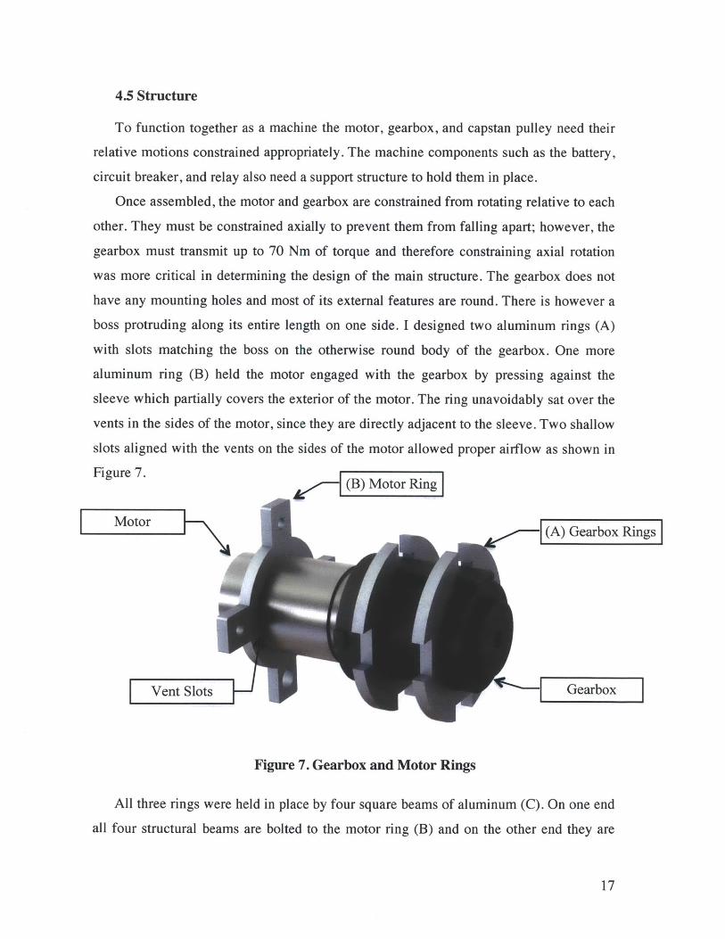
4.5 Structure
To function together as a machine the motor, gearbox, and capstan pulley need their
relative motions constrained appropriately. The machine components such as the battery,
circuit breaker, and relay also need a support structure to hold them in place.
Once assembled, the motor and gearbox are constrained from rotating relative to each
other. They must be constrained axially to prevent them from falling apart; however, the
gearbox must transmit up to 70 Nm of torque and therefore constraining axial rotation
was more critical in determining the design of the main structure. The gearbox does not
have any mounting holes and most of its external features are round. There is however a
boss protruding along its entire length on one side. I designed two aluminum rings (A)
with slots matching the boss on the otherwise round body of the gearbox. One more
aluminum ring (B) held the motor engaged with the gearbox by pressing against the
sleeve which partially covers the exterior of the motor. The ring unavoidably sat over the
vents in the sides of the motor, since they are directly adjacent to the sleeve. Two shallow
slots aligned with the vents on the sides of the motor allowed proper airflow as shown in
Figure 7. (B) Motor Ring
Motor(A) Gearbox Rings
Vent Slots |- N Gearbox
Figure 7. Gearbox and Motor Rings
All three rings were held in place by four square beams of aluminum (C). On one end
all four structural beams are bolted to the motor ring (B) and on the other end they are
17

bolted to the innermost of two bearing holders (D). Together, the four beams, the motor
ring, the two gearbox rings, and the inner bearing holder form a cage which encloses and
sufficiently constrains the motor and gearbox as shown in Figure 8. The cage was also
designed to transfer static forces around, rather than through, the motor and gearbox.
(B otor Ring
(A) Gearbox Rings
(D) Inner Bearing Holder(C) Beams
Figure 8. Structural Beams
Power is transmitted from the gearbox to the capstan pulley via a keyed drive shaft
(E) as shown in Figure 9. The shaft is supported at both ends of the pulley by ball
bearings (F) which are pressed into the inner and outer bearing holders, (D) and (G).
(D) Inner Bearing Holder
(E) Drive Shaft
(G) Outer Bearing Holder
Figure 9. Drive Shaft and Outer Bearing Holder
18

The capstan pulley (H) has two main functional requirements. First, it must transmit
power to the rope through friction and in doing so convert rotary motion into linear
motion. This was accomplished by making the pulley long enough to accommodate
sufficient wraps of rope for the necessary tension ratio, as dictated by equation 2.1.
Second, the capstan pulley must allow the rope to feed onto and off of it in such a way
that the rope does not begin to bunch up or cross itself. The ends of the pulley have
splined curves forming the transition between a steeply sloped lip and the flat middle of
the pulley, as can be seen in Figure 10. This curves acts as a wedge to ease the rope onto
the pulley while gently sliding the previous coil towards the center of the pulley.
Splined Curve
(H) Capstan Pulley
Figure 10. Capstan Pulley
I designed a pulley cover (I) to enclose the pulley, preventing loose clothing or
appendages from becoming caught in-between the rope and the capstan pulley. It also
was designed to constrain rotation of the outer bearing holder and to help keep rope from
crossing over itself and bunching during operation of the ascender. The cover has four
slots at one end which interlock with the four lugs of the inner bearing holder. The top
slot extends an inch past the edge of the pulley, allowing rope an inlet to the pulley, as
can be seen in Figure 11. The bottom slot extends the full length of the cover, allowing
rope out of the ascender and securing the outer bearing holder (G).
19
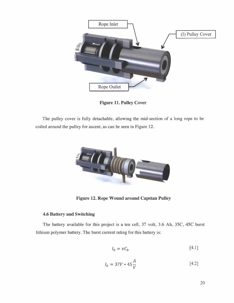
Rope Inlet
(I) Pulley Cover
Rope Outlet
Figure 11. Pulley Cover
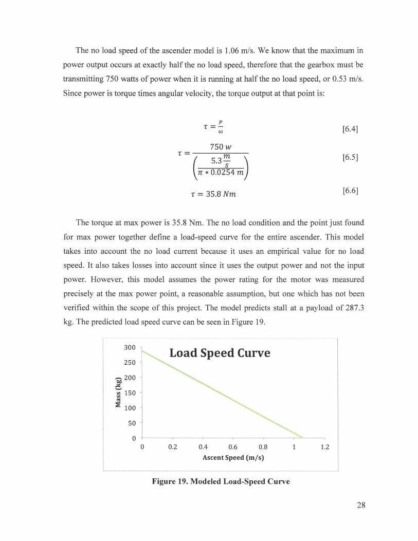
The pulley cover is fully detachable, allowing the mid-section of a long rope to be
coiled around the pulley for ascent, as can be seen in Figure 12.
Figure 12. Rope Wound around Capstan Pulley
4.6 Battery and Switching
The battery available for this project is a ten cell, 37 volt, 3.6 Ah, 35C, 45C burst
lithium polymer battery. The burst current rating for this battery is:
Ib = vCb
AIb = 37V * 45-
V
[4.1]
[4.2]
20

Ib = 162A [4.3]
The burst current rating quantifies the highest current which is safe to draw from the
battery for a few seconds. The tests for the alpha-prototype last less than five seconds
each, which keeps the battery operating within the burst discharge regime. I wired a 150
amp circuit breaker into the ascender's circuit between the battery and the relay to
prevent the relay, motor, or battery from exceeding safe current limits. Given the voltage
and current in a circuit we can find the power:
P = IV [4.4]
P = 150A * 37V [4.5]
P = 5,550W [4.6]
Now we can find the maximum ascent speed which could be achieved with an ideal
(100% efficient) machine lifting 100 kg:
P = vaMg [4.4]
PVa =Mg [4.5]
Mg
Va 5,55OW [4.6]S100kg * 9.8m/s
va = 5.66 m/s [4.7]
This model for top ascent speed does not take any losses into account and the
estimate is therefore entirely unrealistic. However, it is useful as an upper bound to
determine efficiency requirements: the ascender must have an overall efficiency of 9% or
above when lifting a 100 kg payload in order to achieve the target functional requirement
of 0.5 meters per second.
To transmit power from the battery to the motor requires a switch. Testing the device
required a switch connected to the ascender with long leads. Running over 100 amps
through a hand held switch is both unsafe and expensive. As an alternative, I used a small
21

momentary switch wired to a heavy duty automotive relay. The contacts in this relay are
specifically designed for high amperage DC circuits. Figure 13. below pictures theascender with battery and circuit breaker attached. Figure 14. is a complete circuit
diagram for the ascender, showing the ten cell battery, relay and momentary switch, DCmotor, and circuit breaker:
Relay (beneath battery)
... Lithium PolymerBattey
Circuit Breaker
Figure 13. Ascender with Electronics
e M
37 V -- 150 A
Figure 14. Ascender Circuit Diagram
22
J---\

4.7 Harnessing
Users must secure themself to the device in order to ascend with it. A proper climbing
harness is necessary for this purpose. I designed an additional harness, pictured in Figure
15., as a permanent part of the ascender for the purpose of connecting the body of the
ascender and the climbing harness in a stable fashion. The design of the structural frame
provides two attachment points via mounting plates (A) bolted to the motor ring and the
outer bearing holder; one on each side of where rope spools onto the capstan pulley.
Stability is maintained by the wide base which keeps the axis of the ascender roughly
horizontal during operation. The machine harness consists of two loops of one inch nylon
webbing (B) strung through both mounting plates. A carabiner from the climbing harness
is looped through an eye in the middle of the webbing (C).
(A) Mounting Plate
(B) Nylon Webbing
(C) Eye for Carabiner
Figure 15. Ascender Harness
5. Building the Prototype:
An exploded view of the final alpha-prototype ascender design, including electronics
and harnessing, can be seen pictured in Figure 16.
23

(12)
(16
)0
(6)(1)
(10)
U
10)(5)
(14))
(7)
(8) i
(17)
(1) Dew
alt Motor
(2) Dew
alt Gearbox
(3) Capstan P
ulley (4) B
attery (5) C
ircuit Breaker
(6) Relay
(7) Pulley C
over
(8) Ball B
earing (9) Drive Shaft (10) Structural B
eams (11) L
ocating Beam
(12)
Motor R
ing (13) Gear R
ings
(14) Inner Bearing H
older (15) O
uter Bearing H
older (16) M
ounting Plates
(17) Nylon W
ebbing Harness
Figu
re 16. Com
plete A
scend
er -E
xplod
ed V
iew
(NI
(4)
D (16)

5.1 Manufacturing Methods
A variety of methods were used to fabricate the various components of the alpha
prototype. All fabrication methods were carried out on manual machines with the
exception of a water jet. The fabrication procedures for each part can be found in Table 2.
Component: Material Process/ Machine(s)
Gearbox rings 1" aluminum plate cut with water jet
Motor ring " aluminum plate cut with water jet
holes finished in drillpress
Inner bearing holder 34" aluminum plate cut with water jet
pocket milled in vertical mill
holes finished in drillpress
Outer bearing holder " aluminum plate cut with water jet
pocket milled in vertical mill
holes finisheqd in drillpress
Bottom structural 3" aluminum plate cut with water jet
beam (used to index end holes drilled then tapped in lathe
the gearbox rings)
Remaining structural 3" square extruded rough cut on bandsaw
beams aluminum bar ends cleaned up on vertical mill
end holes drilled then tapped in lathe
Drive shaft 1144 Carbon Steel turned, drilled and tapped on a lathe,
keyseat and flats added in vertical mill
Capstan pulley curved 3" aluminum bored, faced, and turned in lathe
extruded round keyway broached in an arbor press
set screw hole drilled and tapped in
vertical mill
Pulley cover 3" OD aluminum bored in lathe
tubing slots cut in vertical mill
Table 2. Manufacturing Methods by Component
25

5.2 Difficulties during Build
Originally, I intended to machine the pulley on a CNC lathe due to the difficulties in
machining a spline with a manual machine. However, the CNC lathes were not available.
Instead, I used a custom ground tool bit. The bit was ground to match the spline of the
capstan pulley using a 1:1 scale printing of the CAD drawing.
The gearbox had several slight protrusions which were not accounted for when
making the original CAD model. During assembly I discovered interference between
these protrusions and the structural beams. I marked the beams and milled shallow slots
in them to eliminate the interference, permitting me to assemble the ascender correctly.
Both contacts on the automotive relay were located on the same end, quite close
together, presenting a dangerously easy way to short circuit the device and inadvertently
cause it to begin operating. To prevent this eventuality, I shrunk several layers of shrink
tubing around the exposed contacts to insulate them.
The bolt fastening the inner bearing holder to the top structural beam interfered with
the rope as it fed into the pulley. This problem arose from using a CAD model which did
not contain fasteners. I lengthened the inside lip and the shortened the center by one
quarter of an inch to account for this difference.
The completed ascender is pictured in Figures 17. and 18.
Figures 17. Completed Ascending Unit with Cover On
26

Figure 18. Completed Ascending Unit with Cover Off
6. Mathematical Models of the Ascender
During the construction of the physical ascender, a mathematical model of several
key aspects was also created.
6.1 Generating a Load-Speed Curve
The Dewalt motor came with most of the information one would expect to
accompany a DC motor for design purposes. However, the gearbox came with only two
pieces of information: the no load speed in low gear is 400 rpm, and the max power
output of the gearbox motor combination is 750 watts.
Taking our starting point of 400 rpm and the pulley diameter we can find the no load
speed for the ascender:
v,, = onrD, [6.1]
1mvnj = 400 rpm * 2w rads * - * w * 0.0254 m [6.2]
60 s
VnI = 1.06 m/s [6.3]
27
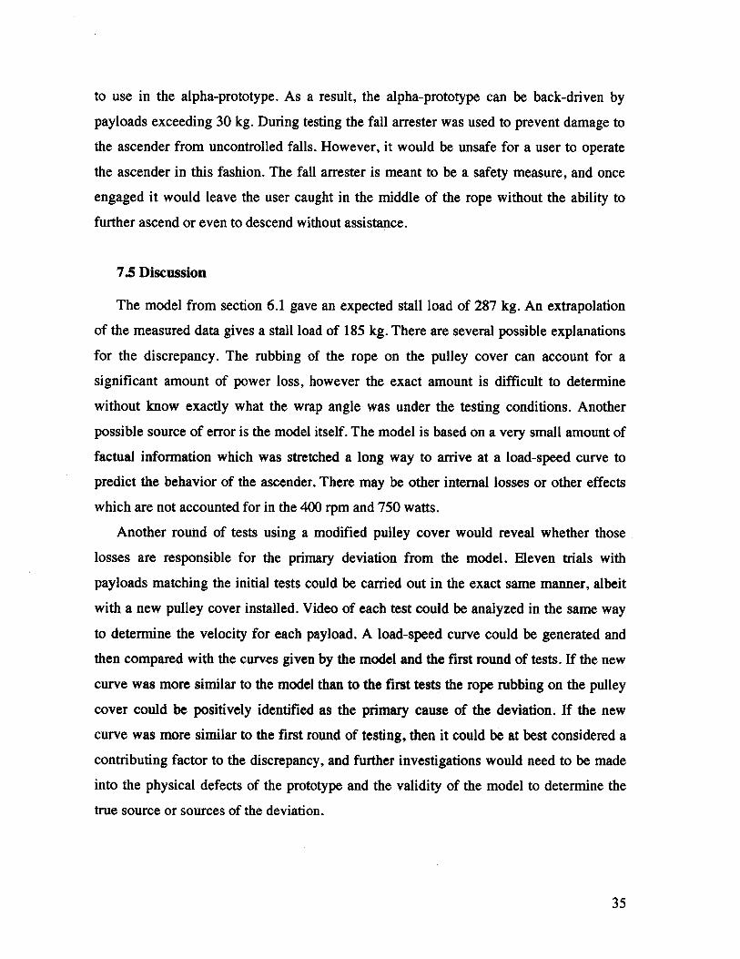
The no load speed of the ascender model is 1.06 m/s. We know that the maximum in
power output occurs at exactly half the no load speed, therefore that the gearbox must be
transmitting 750 watts of power when it is running at half the no load speed, or 0.53 m/s.
Since power is torque times angular velocity, the torque output at that point is:
p= - [6.4]
750 w5.3 M [6.5]
r * 0.0254 m
- = 35.8 Nm [6.6]
The torque at max power is 35.8 Nm. The no load condition and the point just found
for max power together define a load-speed curve for the entire ascender. This model
takes into account the no load current because it uses an empirical value for no load
speed. It also takes losses into account since it uses the output power and not the input
power. However, this model assumes the power rating for the motor was measured
precisely at the max power point, a reasonable assumption, but one which has not been
verified within the scope of this project. The model predicts stall at a payload of 287.3
kg. The predicted load speed curve can be seen in Figure 19.
300 Load Speed Curve250
200
150
100
50
0 0.2 0.4 0.6 0.8 1 1.2
Ascent Speed (m/s)
Figure 19. Modeled Load-Speed Curve
28

6.2 Capstan Model
To predict how much tension is required on the downward line, I made a model of the
capstan and rope using Equation 2.1. For R = .27 as measured between fibrous materials
and aluminum, and a wrap angle of 0 = 6n, or three complete wraps:
= e(o.27 *62r) = 0.023 [6.7]T2
Therefore, for a load of 1000 Newtons, the device requires at least 23 Newtons of
tension in the downward rope. If the tension is-greater than 23 Newtons, the capstan
pulley will transfer enough torque and the ascender will move. If the downward tension is
less than 23 Newtons, the rope will slip and the ascender will not lift its payload. This
model predicts that hanging 2.5 kg on the doynward side of the rope will provide
sufficient tension for the ascender to lift a 100 kg ptyload.
7. Testing and Results
After completing the prototype, I proceeded to conduct tests to determine if the
ascender met the target functional requirements and to assess how accurately my models
predicted the behavior of the physical system.
7.1 Testing the Ascender
Standard gym equipment provided a frame for attaching the rope and testing the
device. Weights for the payload were placed onto a lifting bar attached to the ascender
via a heavy carabiner. The rope was then wrapped three times around the capstan pulley
and tightened. Tension on the downward side of rope was maintained by hanging smaller
weights on the end of the rope. The ascender was controlled by a momentary switch
connected by long leads to the power relay.
Eleven tests were conducted with payloads varying from 10 to 120 kg. The ascender
pulled the weights approximately 2 meters up the rope. An assistant videotaped each test
for later analysis. An ammeter with sufficient capacity for this project was not available.
29

As a result the amperes into the motor and thus the power input and the efficiency had to
be derived from the data which was collected on ascent speed. See Figure 20.
Figure 20. Testing Setup
7.2 Data Analysis
For each test video I used LoggerPro to determine the velocity of the ascender. The
gym equipment used as a frame has pegs spaced vertically at exactly 7 inches. These pegs
provided an accurate distance scale for each video. The video camera used for the tests
has a frame rate of 29.97 fps. To determine the velocity of the ascender in each test, I
measured the vertical displacement of a consistent point on the rear end of the motor
shaft between successive frames for the entire ascent. Then scaled distance by setting the
length between pegs in the video to 7 inches (0.178 meters). To find the ascent velocity in
meters per second I took the average of the scaled displacement multiplied by the frame
rate.
30

To find the power output for each test I multiplied the weight (in Newtons) by the
speed in meters per second. The efficiency at each point is equal to the power going out
of the system divided by the power going into the system and could then be found in one
step.
7.3 Results
Total Mass (kg) Measured Speed (m/s) Predicted Speed (m/s)
17.291 0.756 0.99621.836 0.786 0.97926.382 0.752 0.96330.927 0.765 0.94640.018 0.656 0.91249.109 0.635 0.87962.745 0.557 0.82868.182 0.441 0.77881.818 0.395 0.728
100.000 0.385 0.661121.836 0.424 0.610
Table 3. Measured and Predicted Ascent Speeds
The results of the eleven tests can be seen in Table 2 along with the velocities
predicted by the model shown in Figure Measured velocities ranged from 0.79 m/s for
17.3 kg to 0.42 m/s for a load of 121.8 kg.
The load-speed curve for the ascender was constructed from test data and was
extrapolated for the entire range between no-load and stall and can be seen along with the
predicted load-speed curve in Figure 21.
31

300 Load Speed Curve250
200
150Measured
100 Predicted
50
00 0.2 0.4 0.6 0.8 1 1.2
Ascent Speed (m/s)
Figure 21. Ascender Load-Speed Curve
The model for the tension drop across the capstan was tested by choosing a T,
which will be larger than T2 * 0.023 for the smallest T2 values and smaller than T2 * 0.023
for the largest T2 values. If the model was correct, in one of the tests there would not be
enough tension required to lift the payload and the rope would slip on the capstan pulley.
The pair of successive tests at which the no-slip/slip event occurs put upper and lower
bounds on the ratio, T,, T,, and determine how well the model predicted the outcome.
The initial tension on the downward end of the rope was 2 kg. The model predicted
that the rope would slip with a load of 86.4 kg. The rope slipped at the 100 kg test, but
not at 81.8 kg, the previous test. The model is therefore confirmed to be accurate to
within twenty percent. This is sufficient to create guidelines for users on how much
weight to use when tensioning the downward end of the rope.
7.4 Problems and Suggested Solutions
Several problems arose when testing the device, two of which are safety concerns and
require a redesign and rebuild of several components before user testing could be safely
conducted.
32

Reaction force between the gearbox and the structural frame broke a piece of the
plastic shell surrounding the gear train. Since the part was primarily intended for dust
protection and was not required for the gearbox to function safely, testing was continued
without it. This problem could have been avoided either by providing more clearance for
that part or by using a gearbox with a metal housing.
As it spooled onto the capstan, the rope rubbed against the edge of the pulley cover
with enough force to fray it noticeably over the course of the eleven tests. In addition to
damaging the rope, the rubbing was found to be a major source of power loss. Power is
equal to force times velocity:
P =vF P~vF [7.1]
Taking the ratio of power out over power in:
Pout = ToutVout [7.2]Pin Tinvin
Since our rope is not elastic, we know that Vin = Vout:
- -t [7.3]Pin Tin
Power loss can be calculated using the capstan equation:
[7.4]Pin T in
T,T = - [7.5]
- ( [7.6]Pout
33

The wrap angle of the rope around the edge of the pulley cover is approximately 7/3,
and since this interface is also rope and aluminum, the coefficient of friction will still be
g= 0.27.
Pin __ (0.27* )
Pout
= 0.754Pout
[7.7]
[7.8]
The power loss from the rope rubbing on the pulley could easily be as high as twenty-
five percent. This problem can be avoided in future iterations by using low friction
rolling elements to guide the rope into the capstan, or more simply, by redesigning the
pulley cover to allow the rope to enter and leave the capstan tangentially, eliminating any
wrap angle around the inside edge of the pulley cover. See Figure 22.
Rub pin
Clearance
Figure 22. Current Pulley Cover and Proposed Pulley Cover Interact with Rope
The gearbox contains an integral mechanical brake. It was my intention to use this
brake to provide holding ability when the ascender paused in the middle of a rope.
However, the location of the actuator made the brake difficult to the point of impractical
34
to use in the alpha-prototype. As a result, the alpha-prototype can be back-driven by
payloads exceeding 30 kg. During testing the fall arrester was used to prevent damage to
the ascender from uncontrolled falls. However, it would be unsafe for a user to operate
the ascender in this fashion. The fall arrester is meant to be a safety measure, and once
engaged it would leave the user caught in the middle of the rope without the ability to
further ascend or even to descend without assistance.
7.5 Discussion
The model from section 6.1 gave an expected stall load of 287 kg. An extrapolation
of the measured data gives a stall load of 185 kg. There are several possible explanations
for the discrepancy. The rubbing of the rope on the pulley cover can account for a
significant amount of power loss, however the exact amount is difficult to determine
without know exactly what the wrap angle was under the testing conditions. Another
possible source of error is the model itself. The model is based on a very small amount of
factual information which was stretched a long way to arrive at a load-speed curve to
predict the behavior of the ascender. There may be other internal losses or other effects
which are not accounted for in the 400 rpm and 750 watts.
Another round of tests using a modified pulley cover would reveal whether those
losses are responsible for the primary deviation from the model. Eleven trials with
payloads matching the initial tests could be carried out in the exact same manner, albeit
with a new pulley cover installed. Video of each test could be analyzed in the same way
to determine the velocity for each payload. A load-speed curve could be generated and
then compared with the curves given by the model and the first round of tests. If the new
curve was more similar to the model than to the first tests the rope rubbing on the pulley
cover could be positively identified as the primary cause of the deviation. If the new
curve was more similar to the first round of testing, then it could be at best considered a
contributing factor to the discrepancy, and further investigations would need to be made
into the physical defects of the prototype and the validity of the model to determine the
true source or sources of the deviation.
35

8. Conclusion
The alpha-prototype successfully demonstrated the feasibility of an inexpensive
personal ascender. Transitioning that ascender from the prototype stage to a mass-
manufactured product would require many changes to the methods employed in its
construction.
8.1 Feasibility
The alpha-prototype successfully lifted over 100 kg up a rope at speeds of nearly half
a meter per second, matching or beating every other ascending device currently on the
market, with the exception of the atlas ascenders. Several aspects of the design still need
to be optimized to reduce manufacturing costs and increase efficiency; however the
feasibility of such a product has been conclusively established.
8.2 Design Changes for Mass Production
Instead of a structure comprised of eight water jet-cut and machined aluminum parts,
the structure would be made of fewer parts stamped from steel plate and bolted or riveted
together. A structure made by this method would be more compact and less expensive to
produce.
The interior of the capstan pulley in the alpha-prototype is entirely wasted space.
The volume of this space is comparable to the volume of the planetary gear train, as
shown in Figure 23.
Planetary Wasted Space
Figure 23. Current Configuration of Capstan Pulley and Planetary Gears
36

This wasted space could be eliminated and the overall length of the ascender
shortened by three inches or more by positioning the gearbox inside the capstan pulley.
As shown in Figure 24.
Planetary GasLength Deres
Figure 24. Improved Configuration of Capstan Pulley and Planetary Gears
In this configuration, a bearing large enough to fit over the motor housing would
support the inner end of the pulley. The capstan pulley would be larger in diameter. As a
result it would rotate more slowly, lowering the fatigue cycles on many components of
the ascender and extending its useable life.
Inside the pulley the motor pinion would engage with a custom planetary gear train.
For a modest production run the steel gears would be outsourced and the gear train
assembled in house due to the highly specialized nature if gear hobbing machinery. A
prawl and ratchet wheel would be built into the first stage of the gearbox. This would
prevent the device from having a powered reverse feature, but it would also completely
prevent the ascender from being back-driven and provide stability when pausing in the
middle of an ascent. A steel ring gear would be press fit into the body of the pulley,
forming the last stage of planetary gear reductions. This ring gear would share a matching
feature, such as parallel flats or a hexagonal outer perimeter. Either option would ensure
robust torque transmission without the possibility of slipping. The outer bearing would fit
into the end of the pulley just outside the ring gear. Such a configuration would eliminate
the drive shaft, inner and outer bearing housings, and the gearbox housing by effectively
37
using the capstan pulley for all of those purposes. Decreasing the part count for the
ascender would decrease material, manufacturing, and assembly cost.
Instead of being machined from a large aluminum blank, the pulley would be die
cast. Die-casting is a less expensive process than machining and it does not waste as
much material. A machined pulley could hold much tighter dimensional tolerances,
however that is not needed a isnot needed in this case, making die casting the most
appropriate method when considering any metric.
A production model would require an injection molded plastic shell. The shell
would enclose all the components and structure, locate them relative to each other, and
protect them from dust, moisture, tampering, and falls. It would also create a much more
appealing external appearance. These factors were neglected in the alpha-prototype,
however they are all necessary to consider when designing a marketable product because
of consumer expectation regarding these metrics.
The pulley cover would still be necessary and would be metal to avoid problems
with excessive wear; however, it would be of a design which remained attached to the
rest of the machine when it was not covering the pulley. A kill switch would be installed
in the pulley cover to prevent the ascender from operating when the cover is open. This
feature would serve to increase user safety by preventing many types of potential
accidents at low cost.
The battery would be rechargeable, quickly exchangeable, and have its own custom
shell that fit sleekly into the rest of the unit. This battery form-factor is common in the
power tool industry and is already well liked and intuitive to use for many potential
customers.
The switch would be a momentary grip switch allowing the user to gradually engage
the motor, instead of full on or full off which causes unpleasant jolts. Dewalt uses
momentary switches in its 36v power tools which provide limited variable speed
capability and can safely handle high currents at 36 volts. A similar switch would be the
most suitable option for use in this device.
Overload protection would be much more carefully and exactly tuned, but would still
have a manual reset button on the exterior of the ascender. All electronics would be made
to operate properly in light to moderate rain to ensure full usability and safety for users.
38
8.3 Future Work
The next steps in the development of this project are to solve the remaining
engineering challenges; including a safe and effective braking system, an appropriate
switch mechanism, and fitting a planetary gear train inside the capstan pulley. Once these
challenges are overcome, a beta-prototype can be built using the form and manufacturing
methods outlined in section 8.2, which are better suited for mass production than the
methods used to construct the alpha-prototype. After extensive testing and fine-tuning of
several beta-prototypes, the product would be ready for approval by regulatory agencies
and then production.
39

9. Works Cited
ActSafe Systems, AB, "Act II Power Ascender, Specifications,"
http://www.actsafe.se/product/acc-power accessed on 4-20-14.
Atlas Devices, LLC, "APA-3," http://www.atlasdevices.com/dev/apa.html, accessed on
4-20-14.
Dewalt Industrial Tool Co., "DC910 Owner's Manual" No. 652215-00, (Dewalt,
Baltimore, 2007).
K. L. Johnson, Contact Mechanics, (Cambridge University Press, Cambridge, 1985).
PowerQuick Mfg., LLC, "PQ500-1," http://www.powerquickinc.com/pq500-1.htm
accessed on 4-20-14.
Simpson Winch, Inc., "Product Specifications, Model CS-CW,"
http://www.capstanropewinch.com/ accessed on 4-20-14.
WesSpur Tree Equipment, "Wraptor Gas Powered Ascender, Details,"
http://www.wesspur.com/ascenders/wraptor.html accessed on 4-20-14.
40