design and numerical analysis of reinforced concrete...
TRANSCRIPT

Delft University of Technology October 2007
Design and Numerical Analysis of
Reinforced Concrete Deep Beams
By Moufaq Noman Mahmoud
Presented to the Faculty of Civil Engineering and geosciences
in partial fulfilment of the requirements
for the Degree of
Master of Science in Engineering


DESIGN AND NUMERICAL ANALYSIS OF REINFORCED CONCRETE DEEP BEAMS
Graduation committee _____________________________________ Prof.dr.ir. J.C. Walraven _____________________________________ Dr.ir. P.C.J. Hoogenboom _____________________________________ Ir. W.J.M. Peperkamp


Acknowledgement All praise be to God, the Cherisher and Sustainer of the worlds. Many special thanks to my supervisors, Prof.dr.ir. J.C. Walraven, Dr.ir. P.C.J. Hoogenboom and Ir. W.J.M. Peperkamp for the invaluable guidance they gave during the study. I am also grateful for the assistance provided by Ir. J.A. den Uijl. I want to express my thanks and gratitude to my mother, wife and family for their prayers and support.
Moufaq Noman Mahmoud October 30, 2007
Nieuwegein, The Netherlands


Abstract DESIGN AND NUMERICAL ANALYSIS OF REINFORCED
CONCRETE DEEP BEAMS Many studies and much research have been done on the design and structural behaviour of reinforced concrete deep beams. In these studies different calculation methods were used. The Beam Method has been used for many years, the Strut-and-Tie Method is recently included in the Eurocode and in the ACI code. New computer programs based on the Linear Finite Element Method claim to be user friendly and present a complete packet not only as an analysing tool but also as a design program. This research aims mainly at finding the most economical way to design deep beams. In order to reach this goal eleven often-occurring or challenging deep beams have been investigated. The results have been used to validate the design methods and to expose possible weaknesses in both code compliance and clarity of the design process. Conclusions: The non-linear analyses show that the designs obtained with the previous mentioned methods provide sufficient load carrying capacity for the ULS. For some designs the capacity was much larger than needed. For the SLS, the designs made with both the Strut-and-Tie Method (STM) and the Linear Finite Element Method (L-FEM) show sufficiently small crack widths. Designs made with the Beam Method sometimes give too large crack widths in the SLS. The best deep beam design method for the reinforcement quantities is the L-FEM because it can be done quickly, the result fulfils all performance requirements and the design is economical. However, detailing the reinforcement should be done with complete understanding of the flow of forces in the structure. The continuity and anchorage of the reinforcing bars are essential to obtain a good design. For this the STM needs to be used qualitatively. Recommendations: Effort can be made for STM to be more competitive by simplifying it, and by making it more efficient in using the mesh-reinforcement. Some introduction training on truss-design may also be very helpful for starting engineers. The logical judgement of the structural engineer is key to obtain a good design. Blindly using a program or following a design method may lead to dependency, which may lead to a fatal error. Evaluating and checking the results logically should stay a priority.


Design and Numerical Analysis of reinforced concrete Deep Beams _________________________________________________________
9 October 2007
Index
. . . . . . . . . . . . . . . . . . . . . . . . . . . . . . . . . . . . . . . . . . . . . . . . . . . . . . . . . . . . . . . . . . . . . . . . . . . . . . . . . . . . . . . .
ABSTRACT ........................................................................................... 7
1. INTRODUCTION ......................................................................... 11
2. SPECIFICATIONS........................................................................ 12 2.1 GENERAL ................................................................................. 12 2.2 CODES ..................................................................................... 12 2.3 LOADS AND SAFETY FACTORS..................................................... 12 2.4 ENVIRONMENT ......................................................................... 13 2.5 MATERIALS .............................................................................. 13 2.6 STUDY CASES ........................................................................... 13
3. STRUT-AND-TIE METHOD......................................................... 20 3.1 INTRODUCTION ......................................................................... 20 3.2 DESIGN STEPS ........................................................................... 21 3.3 STUDY CASES ........................................................................... 26 3.4 REMARKS ................................................................................. 49
4. BEAM METHOD .......................................................................... 50 4.1 INTRODUCTION ......................................................................... 50 4.2 DESIGN STEPS ........................................................................... 50 4.3 STUDY CASES ........................................................................... 55 4.4 REMARKS ................................................................................. 69
5. FINITE ELEMENT METHOD (LINEAR) .................................... 70 5.1 INTRODUCTION ......................................................................... 70 5.2 DESIGN STEPS ........................................................................... 70 5.3 STUDY CASES ........................................................................... 71 5.4 REMARKS ................................................................................. 95
6. FINITE ELEMENT METHOD (NON-LINEAR) ........................... 97 6.1 INTRODUCTION ......................................................................... 97 6.2 STUDY CASES ........................................................................... 98 6.3 REMARKS ................................................................................120
7. DISCUSSION OF THE RESULTS................................................122 7.1 COMPLIANCE TO CODES............................................................122 7.2 ECONOMY OF THE DESIGN RESULT .............................................123 7.3 DURATION OF DESIGN PROCESS .................................................127 7.4 CLARITY OF THE DESIGN PROCESS..............................................128
8. CONCLUSIONS AND RECOMMENDATIONS...........................131 8.1 CONCLUSIONS .........................................................................131 8.2 RECOMMENDATIONS ................................................................132
REFERENCES....................................................................................134

Design and Numerical Analysis of reinforced concrete Deep Beams _________________________________________________________
10 October 2007
APPENDIX......................................................................................... 135

Design and Numerical Analysis of reinforced concrete Deep Beams _________________________________________________________
11 October 2007
1. Introduction Reinforced concrete deep beams are widely used structural elements in building construction. Because of the high stiffness of the deep beam it is for example applied to distribute the loads of a building on the piles below or to prevent relative movement or settlement. A common problem in these structures is clearly visible cracks in serviceability conditions. This has its effect on the durability and on the aesthetics of the structure. Two design methods are commonly used to calculate the internal forces and to design the deep beams. 1) The Strut-and-Tie Method (STM) is recommended by the Eurocode and by the code of the American Concrete Institute (ACI Code). 2) The Beam Method is used according the Dutch Code. The latter, has been used for many years but will be replaced soon by the Eurocode. Due to the fast and big progress of the computer technology and programming there have been many programs developed for analysing and designing structures. Engineers use these programs more frequently and sometimes even for small structures. Therefore, a third design method will be used that is based on a linear elastic analysis with the Finite Element Method (L-FEM), using the software ESA PT. Subsequently, the designs were analysed with the non-linear Finite
Element Method (ATENA) (FNL-FEM). This research aims mainly at finding the most economical way to design deep beams. In order to reach this goal eleven often-occurring or challenging deep beams have been investigated; deep beams with rectangular shapes, special shapes and also with different kinds of openings. The results have been used to validate the design methods and to expose possible weaknesses in both code compliance and clarity of the design process. Recommendations are proposed to the design procedures. An advice is given for the best method for designing deep beams.

Design and Numerical Analysis of reinforced concrete Deep Beams _________________________________________________________
12 October 2007
2. Specifications
2.1 General
In this study, the structures are loaded with one load. This is assumed to make the calculations simple and clear. To compare the methods there is no need to use other loads, such as forced deformations, because they will not change the way of using the design methods. The considered structures are:
- Prefabricated elements without prestressing force. Therefore there will be no residual stresses and shrinkage effect.
- Loaded with external dead load and live load. The load situation during transportation or placing of the members is not calculated, because it is mostly not normative.
- Without creep effects.
2.2 Codes
Eurocode 2 part 1-1 [5] is used in designing the deep beams. The reinforcement of the deep beams in art 9.7 of the Eurocode is related exclusively to the Strut-and-Tie Method. Therefore only for the Beam Method the Dutch Code (NEN 6720) [6] has been used to calculate the deep beams.
2.3 Loads and safety factors
First of all it should be noted that the self-weight of the structural member is always neglected. The loads given below are the total loads; which is the summation of external dead loads and live loads. The proportions of the external dead load (DL) and live load (LL) for the concrete structures is estimated to be between 50%,50% and 65%,35%. According to both the Dutch Code (NEN 6702) and the Dutch appendix of the Eurocode [8], the safety load factors are 1,35 for the dead Load alone, and 1,2 for the deal load and 1,5 for the live load in case of combination of the two loads. Combination 1: Only Dead Load Overall safety factor = 1.35*0.65 = 0.8775 (not normative) Combination 2: Dead Load and Live Load When 0.5DL and 0.5LL: Overall safety factor = 1.2*0.50 + 1.5*0.50 = 1.35 When 0.65DL and 0.35LL: Overall safety factor = 1.2*0.65 + 1.5*0.35 = 1.305 Considering the crack control as an issue in this research, chosen is for the last Ultimate Limit State (ULS) combination, with the overall factor 1.305. The reinforcement calculated according to this ULS combination

Design and Numerical Analysis of reinforced concrete Deep Beams _________________________________________________________
13 October 2007
will be less than the other combinations, which makes the structure more sensitive to the cracking in the Serviceability Limit State (SLS).
2.4 Environment
This study is directed to often-occurring structures. None of the structures is assumed to be subjected to sever environmental conditions nor to a chemical materials. The structural members are subjected to a wet weather (environment) without chloride attack. According to table 4.1 of Eurocode 2 part 1-1 [5], is the Environment Class XC4, or according to table 1 of NEN6720 [6], is the environment Class 2. The recommended maximum crack width in both codes is 0.3mm, according to table 7.1N and table 2 respectively. Case 1 is an exception of this rule because the thickness of the member (100mm) is too thin to satisfy the concrete cover requirement. For this case Environment Class XC1 or Environment Class 1 are considered. The recommended maximum crack width is 0.4mm, according to both codes (table 7.1N [5] and table 2 [6]).
2.5 Materials
The concrete used in this study is C30/37. This choice has been made because this study is directed toward the most applicable situations. Most structures are made with concrete in this range. The characteristics for this concrete are taken from table 3.1 of the Eurocode [5] or from table 3 of the NEN [6]. Concrete properties: According to Table 3.1 (Eurocode)
fck fck,cube fcm fctm fctk,0.05 fctk,0.95 Ecm
30 37 38 2,9 2 3,8 33000 Table 1: Concrete properties The reinforcement steel is chosen to have yield strength of 500 MPa.
2.6 Study cases
In discussions with the committee members the following selection is made, based on often-occurring practical situations and practical design problems. The cases are shown below with the total loads for the serviceability limit state (SLS).

Design and Numerical Analysis of reinforced concrete Deep Beams _________________________________________________________
14 October 2007
Figure 1: Case 1
Figure 2: Case 2

Design and Numerical Analysis of reinforced concrete Deep Beams _________________________________________________________
15 October 2007
Figure 3: Case 3
Figure 4: Case 4

Design and Numerical Analysis of reinforced concrete Deep Beams _________________________________________________________
16 October 2007
Figure 5: Case 5
Figure 6: Case 6

Design and Numerical Analysis of reinforced concrete Deep Beams _________________________________________________________
17 October 2007
Figure 7: Case 7
Figure 8: Case 8

Design and Numerical Analysis of reinforced concrete Deep Beams _________________________________________________________
18 October 2007
Figure 9: Case 9
Figure 10: Case 10

Design and Numerical Analysis of reinforced concrete Deep Beams _________________________________________________________
19 October 2007
Figure 11: Case 11

Design and Numerical Analysis of reinforced concrete Deep Beams _________________________________________________________
20 October 2007
3. Strut-and-Tie method
3.1 Introduction
The strut-and-tie models have been widely used as an effective tool for
designing reinforced concrete structures [1]. The principle of the strut-and-tie method is to design a truss where all the stresses are condensed
into compression members and tension members connected by nodes [2]. The concrete is considered to transfer only compressive forces,
while reinforcing steel transfers the tension forces. The designer needs to have experience to choose optimum trusses [1]. Designing a member
using the strut-and-tie method should
begin with determining the
stress distribution in the member caused
by the loading and support condition.
The distribution of the stresses in the
member depends on the shape and place
of the openings, type of loads and supports
of the structure.
Each discontinuity in these members will cause a distortion in the stress flow in the structure.
See the figure for some examples [3]. Defining the disturbed region or the discontinuity region (D-region) and the Bending region (B-region) is
needed because the design of each region differs from the other. The plane sections of the B-region are considered to remain plane. These
regions can be designed by analyzing the sectional forces using traditional methods.
The strut-and-tie method is effective for designing D-regions.
If the structural member presents a complex or unfamiliar stress distribution, elastic finite element analysis can be used to give the
designer an idea of the flow of forces within the uncracked member [2].
There can be more strut-and-tie models each for a different stress
distribution. Some models may be more efficient or logical than the

Design and Numerical Analysis of reinforced concrete Deep Beams _________________________________________________________
21 October 2007
others. The designer should have accounted for all stresses in the member. Since ties are more deformable than concrete struts, a model
with the least number and the shortest ties is likely the best. This requirement can be quantified as the principle of minimum
complementary energy:
.min21
=∑ miiilF ε
Where: Fi is the force in the strut or tie
li is the length of the member ‘i’ εmi is the strain in member ‘i’
Different models can also be combined to reduce the stresses in some
ties and struts.
3.2 Design steps
For design of a structure the same steps were followed for all cases. Because of the repetition use of a spreadsheet would be a proper way to save time. The steps will be described in short as shown below. Step 1: In this step, the main values needed for the calculation are determined, such as, the design values of the compressive and tensile stresses of the concrete and reinforcement, the concrete cover and the maximum allowable stresses in the nodes and struts. As said before the design of the cases is done according to the Eurocode. The values for the strength class for concrete are shown in table 1. The value of the design compressive strength in struts (fcd) is defined as: fcd = αcc.fck / γc Where: γc is the partial safety factor for concrete (for ULS =1,5 and for
SLS =1,0) αcc is a coefficient taking account of long-term effects (is 1,0) The value of the design tensile strength (fctd) is defined as: fctd = αct.fctk,0.05 / γc Where: γc is the partial safety factor for concrete (for ULS =1,5 and for
SLS =1,0) αct is a coefficient taking account of long-term effects (is 1,0)

Design and Numerical Analysis of reinforced concrete Deep Beams _________________________________________________________
22 October 2007
The value of the design tensile strength for reinforcement (fyd) is defined as: fyd = fyk / γs Where: γs is the partial safety factor for steel (for ULS =1,15 and for SLS
=1,0) The value of the design compressive strength in nodes is limited as mentioned in art. 6.5.2 of Eurocode 2 part 1-1. The limitation depends on the type of the node: Maximum compressive strength = v’.fcd (when there is only compressive stress in node C-C-C) Maximum compressive strength = 0.85 v’.fcd (when there is one tensile stress in node C-C-T) Maximum compressive strength = 0.75 v’.fcd (when there are more tensile stresses in node C-T-T) Where: v’ = 1 – (fcd / 250) Step 2: In this step, the minimum and maximum face reinforcement (As;min) and (As;max) are determined according to art. 9.6 and 9.7 of the code, and determine the dimensions of the concentrated load and supports. As;min = 0,1% * Ac As;max = 2% * Ac Where Ac is the concrete section area According to art. 9.7(1), the minimum face reinforcement area calculated is the area needed in each face and each direction. Therefore, the used area in the horizontal direction will be equal to the area in the vertical direction. The area of the bearing of the concentrated loads and supports will be determined using the maximum compressive stress depending on the type of the stresses in the node considered (C-C-C, C-C-T or C-T-T), where ‘C’ is for compression and ‘T’ for tension. Step 3: Selecting the strut-and-tie model will be done depending on the experience of the designer. Using the program “Dr. Frame” was helpful in refining the design and determining the forces in the bars. “Dr. Frame” is a program developed by “Dr. Software LLC.”. This program is a finite element-based tool to analyse structures. Form the calculated

Design and Numerical Analysis of reinforced concrete Deep Beams _________________________________________________________
23 October 2007
forces the space needed for the struts and ties was checked. The distances between the nodes and the edges are then adjusted, if necessary, according to this calculation. Step 4: Going back to the Excel spreadsheet with the forces in the struts and ties to find the reinforcement bars needed and to check the bearing capacity of the struts forms the main part of this step. Ties: Determining the needed steel area does not form a special calculation. But the used reinforcement will be adjusted to satisfy the conditions of crack width. In this step the needed anchorage length will be calculated according to art. 8.4.2, as fallows: The basic anchorage length (lb;rqd) is defined as: lb;rqd = (φ / 4)*( σsd / fbd) Where: φ is the bar diameter σsd is the design stress in the bar fbd is the ultimate bond stress and defined as: fbd = 2,25 . η1 . η2 . fctd Where: η1 is a coefficient related to the quality of bond (chosen as 1,0) η2 is a coefficient related to the bar diameter (for φ <32 is 1,0 and
for φ>32 is (132 – φ)/100) The design anchorage length (lbd) is defined as: lbd = α1 . α2 . α3 . α4 . α5 . lb,rqd Where: α1 , α2 , α3 , α4 , α5 are rep. coefficients for form, cover,
confinement of the concrete, Welded bars and the compressive pressure on the bars. The values of these coefficients are determined according to art. 8.4.4 of the code.
Struts: The compressive stresses in the struts are already calculated. In this part of the calculations not only the calculated compressive stresses will be rechecked, but also the transverse tension force (T) caused by the curved trajectories in the struts would determined, and the needed reinforcement in its direction would be checked. This will be done conform art. 6.5.3 of the code [5].

Design and Numerical Analysis of reinforced concrete Deep Beams _________________________________________________________
24 October 2007
Because this tensile force (T) is located only in a specific place, depending on the curvature of the trajectories of the compressive stresses, only a part of the face reinforcement, which lies around the location of (T), shall be activated. If b>H/2: Width of tension area =H/4 Otherwise: Width of tension area = b/2 The value of the tension force (T) depends directly on the shape of the stress trajectories, which depends on the width of the member (b) or the available space around the strut. The effective width (bef), where the trajectories can develop, is defined as: If b > H/2: bef = H / 2 + 0.65 a Where: (a) is the width of the loaded area. Otherwise: bef = b The tensile force (T) is: If b>H/2:
hahFT
47.0* −
=
Otherwise:
babFT
4* −
=
The angle between the strut and the horizontal face reinforcement is determined from the truss drawing. This angle would be used to transfer the area of the face reinforcement from its directions (vertical and horizontal) to the direction of the tensile forces (perpendicular to the strut direction). That means that the face reinforcement shall be used to carry this force. As;φ = As;face * {sin (Φ) + cos (Φ)} Where: As;φ is the area of the face reinforcement in the direction of (T). Φ is the angle between the strut and face reinforcement

Design and Numerical Analysis of reinforced concrete Deep Beams _________________________________________________________
25 October 2007
When the face reinforcement is not sufficient to carry this tension force, extra mesh will be placed to satisfy the stress condition of the steel. Step 5: The crack width will be calculated and checked in the serviceability limit state (SLS). The force in the tie is determined with a load factor of 1,0. Although is the strut-and-tie method is described and used in the Eurocode 2 part 1-1, a rule to determine the effective width of ties inside the deep beams is not clearly given. The mentioned rules in art. 7.3.2 are related to the concrete cover (c) [heff=2.5*(h-d)] or to the neutral line of the cross section (x) [heff=(h-x)/3], which not always found in the strut-and-tie model. When the tie lies along the edge of the member, the rule related to the concrete cover can be used, but when the tie lies inside the deep beams an assumption has been made. Two ways are used to determine the effective width of the tie in this case depending on the situation. If the tie has one layer of reinforcement the effective width is assumed to be (φ*5), and when the tie has reinforcement in more layers the effective width is assumed to be 2,5*(C to C distance of the layers). To check the crack width, the expressions given in art. 7.3.4 is used. The crack width (wk) is defined as: wk = sr,max (εsm – εcm) Where: sr,max is the maximum crack spacing. This value must be calculated
with one of two different expressions depending on the C to C distance of the bars. In these calculations it is always chosen to have C to C distance smaller than 5(c + φ/2), which leads to smaller crack width. The used expression was therefore the following:
sr,max = k3 . c + k1 . k2 . k4 . φ / ρp,eff
k1 is a coefficient related to the bond (=0,8) k2 is a coefficient related to the distribution of tension (=1,0) k3 and k4 are 3.4 and 0.425 respectively ρp,eff = As/Ac,eff
(εsm – εcm) is the difference between the mean strains of
reinforcement and concrete, and may be calculated from the expression (without prestressing):
s
s
s
effpeeffp
effctts
EE
fk
σρα
ρσ
εε 6,0)1( ,
,
,
cmsm ≥+−
=−
Where: σs is the stress in tie reinforcement

Design and Numerical Analysis of reinforced concrete Deep Beams _________________________________________________________
26 October 2007
αe = Es / Ecm kt is a factor depending on the duration of the load (for long term
loading kt = 0,4) Step 6: In the beginning of this step a check has been done to see if all the results are good, and if both the input and output satisfy the conditions. Drawing the reinforcement and calculating the amount of reinforcement in the deep beam are the last steps.
3.3 Study cases
Case 1: This case is the only case calculated with dry weather (environment class XC1). This is chosen because of the small thickness of the member (100mm). This thickness gives space for one bar of the main reinforcement in the horizontal direction. The two main bars are anchored to steel plates at the ends of the member, because other solutions are not possible in the available thickness. The support plate length is 200mm and the load plate length is 400mm. The strut-and-tie model is rather simple, two struts between the concentrated load and the supports and one tie between the supports, as shown below.
Figure 12: Strut-and-Tie Model

Design and Numerical Analysis of reinforced concrete Deep Beams _________________________________________________________
27 October 2007
Figure 13: Strut-and-Tie Forces The face reinforcement consists of two meshes of φ6-100mm. The calculation of the tie reinforcement of this case is considered as an example for the other cases, therefore it will be explained with some extra details. Tie reinforcement calculation: Tension force in the tie = 283.3 kN Chosen: 2φ25, with As = 981.25mm2 σs = 283.3*103 / 981.25 = 288.7 N/mm2 (ULS) The tie reinforcement consists of two bars φ25, with a C to C distance of 100mm, as shown in the figure below. Crack width calculation: σs = 288.7 / 1.305 = 221.24 N/mm2 (SLS) hc;eff=2.5*(h-d) = 2.5 *(1000 – 915) = 212.5 mm fct;eff = 2.9 N/mm2 (Table 1) Es = 200 000 N/mm2 Ecm = 33 000 N/mm2 αe = Es / Ecm = 200000 / 33000 = 6.06 kt = 0,4 (for long term loading) Ac,eff = b * hc;eff = 100 * 212.5 = 21250 mm2 ρp,eff = As/Ac,eff = 981.25 / 21250 = 0.0462
s
s
s
effpeeffp
effctts
EE
fk
σρα
ρσ
εε 6,0)1( ,
,
,
cmsm ≥+−
=−
(εsm – εcm) = 0.000945 c = 37 mm (to the main reinforcement bars) k1 = 0.8 k2 = 1.0 k3 = 3.4 k4 = 0.425 sr,max = k3 . c + k1 . k2 . k4 . φ / ρp,eff = 310.0 mm

Design and Numerical Analysis of reinforced concrete Deep Beams _________________________________________________________
28 October 2007
The crack width (wk) is defined as: wk = sr,max (εsm – εcm) = 310.0 * 0.000945 = 0.29 mm
Α
Α
Sec. A-A
φ6-100mm
2φ25φ25
φ6-100mm
φ6-10
0mm
φ25
Figure 14: The reinforcement The calculated crack width is 0.29mm, which satisfy the requirement of environment class XC1, 0.40mm. The weight of the used reinforcement in this member is about 0.331kN. Case 2: The shape of this member is widely used at the ends of the prefabricated beams and bridges. One solution, which has only horizontal and vertical bars, as shown below, has been calculated. Another solution with an inclined tie on the support at the left is also wide practically used.
Figure 15: Strut-and-Tie Model

Design and Numerical Analysis of reinforced concrete Deep Beams _________________________________________________________
29 October 2007
The choice is made to the former because the member is wide enough to put the needed reinforcement (500mm wide) and because of the simplicity of erecting the reinforcement of this option (only horizontal and vertical bars).
Figure 16: Strut-and-Tie Forces The length of both support plate is 100mm and of the load plate is 200mm. The face reinforcement consists of two meshes of φ12-125mm. The ties in this model lie at the lower side of the member, which is expected for any simply supported beam. The reinforcement at the ties AB and CD (6φ25) are heavier than tie DF (5φ25), and that is also expected because of the smaller lever arm at the left side. The C to C distance of the two reinforcement layers is 100mm, as shown in the figure below.
φ25
φ25
φ25
φ25
φ25φ25
φ12-125mm
φ12-12
5mm
φ25
φ25
φ25
φ25
φ12-125mm
φ25
Α
Α
Sec. A-A
φ25
φ25
Figure 17: The reinforcement

Design and Numerical Analysis of reinforced concrete Deep Beams _________________________________________________________
30 October 2007
The maximum calculated crack width is 0.22mm, which satisfy the requirement of environment class XC4, 0.30mm. The weight of the used reinforcement in this member is about 0.800kN. Case 3: This wall with an opening in the middle is loaded with one concentrated load, which does not lie in the middle. The support length is 100mm and the load length is 200mm. The strut-and-tie model has a clear shape with the tie at the bottom of the deep beam, and it has shear force reinforcement in the middle, tie CI, as shown below.
Figure 18: Strut-and-Tie Model This symmetric shape is loaded with asymmetric load. Due to economical reasons, the construction was not symmetric reinforced. The loaded side gets more reinforcement than the other side. Practically, this side must be clearly marked to avoid mistakes by using the member in the wrong direction.
Figure 19: Strut-and-Tie Forces

Design and Numerical Analysis of reinforced concrete Deep Beams _________________________________________________________
31 October 2007
The face reinforcement consists of two meshes of φ8-200mm. Extra meshes of φ8-200mm are placed at the faces beneath the concentrated load. The reinforcement at the ties AE (4φ25) is heavier than tie LK (3φ25) and tie GF (2φ25), and that is expected due to the smaller lever arm at the middle of the beam and the bigger moment. The shear force reinforcement is (6φ12). The C to C distance of the two reinforcement layers is 100mm, as shown in the figure below.
Sec. A-A
φ8-200
φ25
φ25
φ8-200
φ8-200
φ25φ25
φ25
φ25
φ8-200
φ8-200
φ25φ25
φ12
φ12
φ12
φ25
φ25
φ25
Figure 20: The reinforcement The maximum calculated crack width is 0.30mm, which satisfy the requirement of environment class XC4, 0.30mm. The weight of the used reinforcement in this member is about 3.128kN. Case 4: A wall with an opening in the middle is the best description of this deep beam. The support plate length is 100mm and the load plate length is 200mm. The model has small trusses, above and under the opening, with a tie at the bottom of each truss, and a strut at the top. The vertical bars are shear force reinforcement in the middle, as shown below.

Design and Numerical Analysis of reinforced concrete Deep Beams _________________________________________________________
32 October 2007
Figure 21: Strut-and-Tie Model (Case 4)
Figure 22: Strut-and-Tie Forces (Case 4) Although, the strut-and-tie model of this deep beam was easy to be found it was not clear how the distribution of the forces on the upper and lower trusses would be. The expectation was that the tie at the bottom will carry bigger part of the load, in a similar way to the wall without the opening. But, the compression load from the concentrated load is distributed directly in the wall and the tie above the opening carries bigger part of the load. The load at the sides of the opening will go to the supports through compression struts, which need a tie at the bottom of the beam to stay stable.

Design and Numerical Analysis of reinforced concrete Deep Beams _________________________________________________________
33 October 2007
This wall was calculated as shown in the figure above (case 4). But when calculated using the Non-linear Finite Element Method it cracked in places without main reinforcement. A second calculation (case 4a) has been done using extra bars where the cracks occur to determine the forces at these points. The only difference between the two models is at the right hand sides.
Figure 23: Strut-and-Tie Model (Case 4a)
Figure 24: Strut-and-Tie Forces (Case 4a) Model 1 (case 4): The face reinforcement consists of two meshes of φ10-175mm. Extra meshes of φ10-175mm are placed at the faces beneath the concentrated load. The reinforcement at the ties in the upper truss (6φ25) is heavier than the tie in the lower truss (4φ25). The shear force reinforcement is (8φ12) above the opening and (4φ12) under the opening. The C to C distance of the two reinforcement layers is 100mm, as shown in the figure below.

Design and Numerical Analysis of reinforced concrete Deep Beams _________________________________________________________
34 October 2007
Sec. A-A
φ25
φ25
φ10-175
φ12
φ12
φ10-175
φ25φ25
φ6-17
5
φ12
φ12
φ25
φ10-175
φ25φ25
φ25
φ10-17
5
φ25
φ25
φ12
φ12
φ12
φ12
φ10-175
φ12
φ12
φ12
φ12
φ12
φ12
Figure 25: The reinforcement (Case 4) The maximum calculated crack width is 0.25mm, which satisfy the requirement of environment class XC4, 0.30mm. The weight of the used reinforcement in this member is about 7.083kN. Model 2(case 4a): The face reinforcement consists of two meshes of φ10-175mm. Extra meshes of φ10-350mm are placed at the faces beneath the concentrated load. The reinforcement at the ties in the upper truss is (4φ20) and the tie in the lower truss (4φ25). The shear force reinforcement is (8φ12) above the opening and (6φ12) under the opening. The C to C distance of the two reinforcement layers is 100mm, as shown in the figure below.

Design and Numerical Analysis of reinforced concrete Deep Beams _________________________________________________________
35 October 2007
Sec. A-A
φ25
φ20
φ10-175
φ12
φ12
φ10-175
φ10-175
φ25
φ25
φ φφ
φ
φ
φφ
φ
φ
φ
φφφφφφ
φφFigure 26: The reinforcement (Case 4a) The maximum calculated crack width is 0.27mm, which satisfy the requirement of environment class XC4, 0.30mm. The weight of the used reinforcement in this member is about 7.069kN. Case 5: In this case the deep beam does not have any opening and is loaded with a uniformly distributed load. The distributed load is divided into six parts, each part is calculated as a concentrated load. The whole deep beam lies in D-region. Therefore the choice is done to put the ties at the top and bottom of the beam. The support length is 100mm and the load is uniformly distributed.
Figure 27: Strut-and-Tie Model

Design and Numerical Analysis of reinforced concrete Deep Beams _________________________________________________________
36 October 2007
Figure 28: Strut-and-Tie Forces The face reinforcement consists of two meshes of φ8-200mm. The reinforcement in the upper tie is (2φ10) and in the lower tie is (2φ8), which is the first horizontal bar of each mesh.
Sec. A-A
φ8-200
φ8
φ10
φ8-200
φ10
φ8-200
Figure 29: The reinforcement The maximum calculated crack width is 0.20mm, which satisfy the requirement of environment class XC4, 0.30mm. The weight of the used reinforcement in this member is about 1.244kN. Case 6: The shape of this deep beam is similar to a façade of a building. The thickness of the beam (150mm) is also suitable for such construction. The load is uniformly distributed and is rather small (5kN/m in SLS).

Design and Numerical Analysis of reinforced concrete Deep Beams _________________________________________________________
37 October 2007
Figure 30: Strut-and-Tie Model The strut-and-tie model sketched above was not really necessary to carry the loads. Many bars of the truss do not carry any load, and others are bars of the face meshes. That is not only because of the low load, but also because of the bigger stiffness of the left part of the construction (900mm width).

Design and Numerical Analysis of reinforced concrete Deep Beams _________________________________________________________
38 October 2007
Figure 31: Strut-and-Tie Forces The face reinforcement consists of two meshes of φ6-150mm. The reinforcement of both ties at the left and right is (2φ16). Extra horizontal tie (2φ8) is placed above the openings.
Sec. A-A
φ6-150
φ8
φ6-15
0
φ6-150
φ16
φ16
φ8
Figure 32: The reinforcement

Design and Numerical Analysis of reinforced concrete Deep Beams _________________________________________________________
39 October 2007
The maximum calculated crack width is 0.24mm, which satisfy the requirement of environment class XC4, 0.30mm. The weight of the used reinforcement in this member is about 1.379kN. Case 7: In this case the deep beam does not have any opening and is loaded with a uniformly distributed load. The distributed load is divided into four parts, each part is calculated as a concentrated load. As matter of fact, in spite of the inclined edges, forms the whole deep beam a D-region. The strut-and-tie model has now a clear shape with a tie at the bottom (later it seams to be a strut) and a tie at the top of the beam, with struts in between. The support length is 100mm and the load is uniformly distributed.
Figure 33: Strut-and-Tie Model
Figure 34: Strut-and-Tie Forces The face reinforcement consists of two meshes of φ8-200mm. The reinforcement of the tie is (2φ16).

Design and Numerical Analysis of reinforced concrete Deep Beams _________________________________________________________
40 October 2007
Sec. A-A
φ8-200
φ16
φ8-200
φ8-200
φ16
Figure 35: The reinforcement The maximum calculated crack width is 0.22mm, which satisfy the requirement of environment class XC4, 0.30mm. The weight of the used reinforcement in this member is about 1.450kN. Case 8: This case is similar to a corbel with a circular opening. The distributed load is divided into four parts, each part is calculated as a concentrated load. The whole deep beam lies in D-region. To avoid unexpected results, the distances between the truss members and the circle are kept almost equal, and the ties beside the circle are horizontal to each other. The horizontal ties BC and CD do not carry any forces.

Design and Numerical Analysis of reinforced concrete Deep Beams _________________________________________________________
41 October 2007
Figure 36: Strut-and-Tie Model
Figure 37: Strut-and-Tie Forces The face reinforcement consists of two meshes of φ8-150mm. The reinforcement of the ties is as follow: AB (3φ20), BG (2φ20) and EI (2φ20).

Design and Numerical Analysis of reinforced concrete Deep Beams _________________________________________________________
42 October 2007
Sec. A-A
φ8-150
φ20
φ20
φ8-15
0
φ8-150
φ20
φ20
φ20 φ20
Figure 38: The reinforcement The maximum calculated crack width is 0.21mm, which satisfy the requirement of environment class XC4, 0.30mm. The weight of the used reinforcement in this member is about 1.442kN. Case 9: In spite of the big height of the beam, it is classified as D-region, because the height is still smaller than twice the width. Anyway it will be calculated in two ways to check the difference between the two cases. The support plate length is 100mm and the load plate length is 200mm. The strut-and-tie model is formed from two struts between the load and the supports and one tie between the supports, as shown below.

Design and Numerical Analysis of reinforced concrete Deep Beams _________________________________________________________
43 October 2007
Figure 39: Strut-and-Tie Model (Case 9)
Figure 40: Strut-and-Tie Forces (Case 9) The beam is loaded with a concentrated load. To get a uniformly distributed stress in the concrete a tie is placed at a distance of b/2, that is in this case equal to 1,5m from the upper side of the beam. At the lower side there are two supports, which form also concentrated loads, and to get a uniformly distributed load in the concrete another tie is needed at a distance of 1,5m from the lower side of the beam.

Design and Numerical Analysis of reinforced concrete Deep Beams _________________________________________________________
44 October 2007
Because the height of the beam has the space to create this situation it will be also calculated, as shown below.
Figure 41: Strut-and-Tie Model (Case 9b)
Figure 42: Strut-and-Tie Forces (Case 9b) Results of the first case: The face reinforcement consists of two meshes of φ8-200mm. The reinforcement of the tie is (2φ20).

Design and Numerical Analysis of reinforced concrete Deep Beams _________________________________________________________
45 October 2007
Sec. A-A
φ20
φ8-200
φ8-200
φ8-200
φ20
Figure 43: The reinforcement (Case 9) The maximum calculated crack width is 0.18mm, which satisfy the requirement of environment class XC4, 0.30mm. The weight of the used reinforcement in this member is about 1.094kN. Results of the second case: The face reinforcement consists of two meshes of φ8-200mm. The reinforcement of the lower tie is (3φ16), and of the upper tie is (4φ16).
φ16
φ8-200
φφ
Sec. A-A
φ
φ
φ
φ
φ
Figure 44: The reinforcement (Case 9b)

Design and Numerical Analysis of reinforced concrete Deep Beams _________________________________________________________
46 October 2007
The maximum calculated crack width is 0.20mm, which satisfy the requirement of environment class XC4, 0.30mm. The weight of the used reinforcement in this member is about 1.277kN. Case 10: The lower part of this deep beam forms a D-region (3m height) – height of D-region is equal to the width of the beam – and the other 1m is a B-region. The distributed load is divided into two parts. The strut-and-tie model consists of a strut between the two imaginary load points at a distance of b/2 from the supports, two struts from these load points and the supports and one tie between the supports, as shown below. The support plate length is 100mm.
Figure 45: Strut-and-Tie Model
Figure 46: Strut-and-Tie Forces

Design and Numerical Analysis of reinforced concrete Deep Beams _________________________________________________________
47 October 2007
The face reinforcement consists of two meshes of φ8-200mm. The reinforcement of the tie is (2φ20).
Sec. A-A
φ20
φ8-200
φ8-200
φ8-200
φ20
Figure 47: The reinforcement The maximum calculated crack width is 0.19mm, which satisfy the requirement of environment class XC4, 0.30mm. The weight of the used reinforcement in this member is about 1.094kN. Case 11: This famous shape is the only statically indeterminate case in this study. The choice is made to the below strut-and-tie model, which consists of two ties, upper and lower, and four struts connecting each load with the supports. The model divides the intern forces between the two ties, and therefore the expected crack width would be smaller. The length of the support plate at the sides is 100mm, in the middle is 200mm and the load plate length is 200mm.

Design and Numerical Analysis of reinforced concrete Deep Beams _________________________________________________________
48 October 2007
Figure 48: Strut-and-Tie Model
Figure 49: Strut-and-Tie Forces The face reinforcement consists of two meshes of φ8-200mm. The reinforcement of the upper tie is (2φ20) and of the lower tie is (3φ20).

Design and Numerical Analysis of reinforced concrete Deep Beams _________________________________________________________
49 October 2007
φ20
φ8-200
φ20
Sec. A-A
φ8-200
φ8-200
φ20
φ20
Figure 50: The reinforcement The maximum calculated crack width is 0.20mm, which satisfies the requirement of environment class XC4, 0.30mm. The weight of the used reinforcement in this member is about 1.079kN.
3.4 Remarks
Sometimes it was not obvious to make good predictions for the forces in the members. An attempt was made to avoid using reinforcement in other directions than horizontal and vertical, only if it was necessary or preferable. Inclined bars were designed just once in case 8. With horizontal and vertical bars, the fabrication of the reinforcement would be easier and cheaper.

Design and Numerical Analysis of reinforced concrete Deep Beams _________________________________________________________
50 October 2007
4. Beam method
4.1 Introduction
The Beam Method is the calculation method of the Dutch Code NEN
6720. The deep beam according to the Beam Method can be calculated as a normal beam taking into account some extra measures. The
measures are listed below: 1. The lever arm (z) between the intern compression and tension
stresses is limited, according to art. 8.1.4. 2. For calculating the shear stress, the total height must be used
instead of the lever arm (d), art. 8.2.2. 3. Extra horizontal reinforcement must be used in the distance z
(lever arm), where As;horizontal related to the vertical shear reinforcement (As;v;vertical), art. 8.2.4.
4. The reinforcement in the tension zone is more or less distributed, according to art. 9.11.3.
5. Minimum horizontal face-reinforcement must be used, where c-to-c not larger than 300mm, art. 9.11.4.2.
6. Reinforcement should be used near the opening or near the changes in the section shape. This reinforcement should be able
to carry the total shear force at that place, art 9.11.7. 7. In some cases, split reinforcement should be used, art. 9.13.1.
Some of these conditions and the explanations given in the Dutch Code
are bringing the result of this method closer to that of the strut-and-tie method, which mentioned in the code without giving any rules to work
it out, art. 9.11.7.1. For example, when the Dutch code in art. 8.1.4 gives a limitation to the compression angle (between 40o and 60o), and
when it gives regulations about the use and place, where the split reinforcement should be.
In case that the beam method does not directly applicable by one of the cases, because of the shape of the opening of that case, a design
should be found that suits the special case and do not much deviate form the principles of the beam method.
Here should be noted that the designer should stick to the rules of the Beam Method, and do not make any combination between this method
and any other design method, which will be studied in this research. Any combination, if any, should be considered as a new method.
4.2 Design steps
Step 1: In this step, the main values needed to begin with the calculation would be determined, such as, the design values of the compressive

Design and Numerical Analysis of reinforced concrete Deep Beams _________________________________________________________
51 October 2007
and tensile stresses of the concrete, the concrete cover and the maximum allowable stresses at the supports and the concentrated load. The values for the strength classes for concrete are taken from table 3 of NEN 6720 [6]. The below values are calculated according to art. 6.1 [6]. The value of the design compressive strength for concrete (f’c) is defined as: f’c = f’crep / γm Where: f’crep = 0.72* f’ck γm is the partial safety factor for concrete (for ULS =1,2 and for
SLS =1,0) The value of the design tensile strength for concrete (fc) is defined as: fc = fcrep / γm Where: fcrep = 0.7(1.05 + 0.05 f’ck) γm is the partial safety factor for concrete (for ULS =1,4 and for
SLS =1,0) The value of the design tensile strength for concrete under bending (fcr) is defined as: fcr = (1.6 – h) fcm Where: fcm is the average tensile strength for concrete The value of the design tensile strength for reinforcement (fyd) is defined as: fyd = fyk / γs Where: γs is the partial safety factor for steel (for ULS =1,15 and for SLS
=1,0) Step 2: The determination of the design moment and shear force is the first step in this designing method. The most cases are simply supported beams, others are fixed and one case is a continuous beam (on three supports). The determination of the design moment and shear force is done as usual. In this step the dimensions of the supports and load will be also determined. The split reinforcement is only needed if the compression stress under the concentrated load higher than (0.7*f’c), art. 9.13.1.

Design and Numerical Analysis of reinforced concrete Deep Beams _________________________________________________________
52 October 2007
The choice is made to avoid this situation by using this stress as the upper limit. Max used compressive stress = 0.7 * f’c Step 3: To determine the lever arm between the tension and compression stresses not only the rules according to art. 8.1.4. are considered, but the shape and eventually the openings in the deep beam will play also a role. The judgment of the designer will be essential in choosing the used model. A deep beam according the Dutch code has:
lof / h ≼ 2.0 The lever arm of a continuous deep beam (z), art 8.1.4:
z = 0.3 lo + 0.3 h ≼ 0.75 lo Where: For the fields: lo = lof For the supports: lo = los lof is the distance between two field points where the moment is
zero. los is the distance between two points by the supports where the
moment is zero. The lever arm of a simply supported deep beam (z), art 8.1.4:
z = 0.2 l + 0.4 h ≼ 0.6 l Where: l is the distance between the supports. h is the maximum height of the beam. The lever arm of the corbel (z), art 8.1.4:
z = 0.2 l + 0.4 h ≼ 0.8 l
Where: l = 2a where (a) is the length of the load. h is the maximum height of the corbel. Step 4: Choosing the reinforcement will be done according to the calculated lever arm. The ultimate moment (Mu): Mu = As.fs.z (art. 8.1.4) The area calculated will be checked with the minimum reinforcement area. The minimum reinforcement is the area needed to carry the loads when the concrete cracks (Mr), art. 9.9.2.1 [6]. Md = Mr = 1.4 fcm W

Design and Numerical Analysis of reinforced concrete Deep Beams _________________________________________________________
53 October 2007
The anchorage length is calculated conform art 9.6 [6].
c
skvo f
fl'1φα=
Where: lvo is the basic anchorage length
24.0)1.01(4.01 ≥−=k
cφ
α
φk is the bar diameter c is the concrete cover to the bar The anchorage length (lv) will be equal to the basic length when the bar diameter is 25mm or less. Otherwise it will be 1.25*the basic length. The anchorage length may be reduced to (lvr) if the stress in the bars less than the yield stress.
mmllf
l vv
s
sdvr 70
5≥≥=
σ
Step 5: Calculating the needed vertical shear reinforcement (stirrups) is done as follows: The design shear stress (τd): τd = Vd / bh (art. 8.2.2) The ultimate shear stress in concrete (τ1):
τ1 = 0.4 * fc * kλ kh ≽ 0.4 fc (art. 8.2.3)
Where: kλ = 1,0 (kλ) is the effect of big thickness, art. 8.2.3.1 [6]. Or for a corbel or when consider the beam part with free end support, where a compression diagonal (strut) can form between the load and the end support, (kλ) can be calculated as follows:
0.1123 ≥=
bhA
gk o
λλ
For: 6.0≥vλ
21 vg λλ +=
For: 6.0<vλ
36.135.2 ≥−= vg λλ
max
max
d
dv hV
M=λ
Mdmax is the maximal absolute value of the moment Vdmax is the maximal absolute value of the shear force Ao is the smallest area of the load or the support

Design and Numerical Analysis of reinforced concrete Deep Beams _________________________________________________________
54 October 2007
kh = 1.6 – h ≽ 1.0 where (h) in meters
s
dsv fz
VVA.
1−=
Where Asv is the area of the vertical shear reinforcement per unit of length. The shear reinforcement shall be applied vertically. Extra horizontal reinforcement should be uniformly distributed in (z). The area of the horizontal reinforcement per unit of length should be equal to the vertical shear reinforcement per unit of length if (λv) was smaller than 0.4, otherwise the area should be twice the vertical reinforcement, art. 8.2.4 [6]. Step 6: Minimum distributed horizontal reinforcement and reinforcement by the opening shall be also determined. There are two conditions for the extra horizontal reinforcement; the c-to-c distance should be not more than 300mm, and the reinforcement should be able to limit the crack width to the accepted value, art. 9.11.4.2. The second condition will be checked according art 8.7.2. The estimated stress in the horizontal face reinforcement should be used to check the bars with the limitations of table 36 of the Code, for the diameter, and table 37, for the bar distance. The reinforcement by the opening must be able to carry the whole shear force at that section, art. 9.11.7. As = Vd / fy This reinforcement should be distributed over a distance not larger than: Distance < ho * cotg θ Where θ is the angle with the horizontal line and lies between 30 o and
60o. ho is the height of the beam-part Step 7: Crack width control will be done according to art 8.7. The control should be done in the SLS, and has two criteria based on the bar-distance and the diameter of the bars. The first step here is to check the stress in the uncracked concrete section, and then to use the suitable table to make the check. If the stress in the uncracked concrete section bigger than (fcm), the check will be according art 8.7.2, as stabilized cracking stage. Otherwise it will be done according to art. 8.7.3, as an unstabilized cracking stage.

Design and Numerical Analysis of reinforced concrete Deep Beams _________________________________________________________
55 October 2007
In the check, the diameter and bar distance will be compared with the limits given in the NEN. These limits are related to the stress in the bars and to the environmental class.
4.3 Study cases
For all cases, the calculated load- and supports areas are the same as found in the strut-and-tie model. Therefore it will not be mentioned. The crack width will be checked. The check will be done with the values in the NEN tables related to environment class 2. According to the NEN 6720, the maximum allowable crack width for environment class 2 is 0,3mm. Case 1: As a normally loaded simply supported beam, the shear force line and moment lines are calculated: V-line:
Vd = 260kN M-line:
Md = 234kN.m The calculation of the reinforcement of this case is considered as an example for the other cases, therefore it will be explained with some extra details. l = 2000 mm h = 1000 mm
z = 0.2 l + 0.4 h ≼ 0.6 l = 760 mm fy = 435 N/mm2 As;needed = 234*106 / (435*760) = 708 mm2 The main reinforcement used is 2φ25, As = 981.25 mm2 σs = 234*106 / (981.25*760) = 314 N/mm2 The main reinforcement is found to be 2φ25 with a bar distance of 100mm. Shear force reinforcement is needed φ6-300mm, and that is not much. That is because of the effect of the factor kλ, which gets a high value when the possibility of forming a compression strut between the load and the support exists, art. 8.2 [6].

Design and Numerical Analysis of reinforced concrete Deep Beams _________________________________________________________
56 October 2007
Α
Α
Sec. A-A
φ6-300mm
2φ25
φ
φ φ
φ
Figure 51: The reinforcement As mentioned by the Strut-and-Tie Method this case is the only case with another environmental class than the others. This case has a small thickness (100mm) and therefore it is considered to lie in a dry environment class 1. The crack width may be 0,4mm. In this case, the crack width is in stabilized cracking stage, and the stress in the steel bars is (314 / 1.305 = 240 N/mm2). The code gives two conditions, but asks to satisfy only one. It was the bar distance which mostly satisfied. Using the stress in the bars, the environmental class with table 37 of the NEN to get the maximum limit of the bar distance, which is 270mm. This is bigger than the used 100mm. The weight of the used reinforcement in this member is about 0.213kN. Case 2: V-line:
Vd = 355kN
Vd = 426kN M-line: Md = 88.9kN.m
Md = 213kN.m This beam has been divided from the concentrated loading into two parts. The left side is calculated as a corbel (Md = 88.9kN.m) and the right side is calculated as an end of a deep beam (Md = 213kN.m).

Design and Numerical Analysis of reinforced concrete Deep Beams _________________________________________________________
57 October 2007
The calculation of the corbel is done with the height of the left side (400mm), and it results in main reinforcement of 4φ20 and stirrups of φ8-100mm, which will be applied horizontally too. On the other hand, the right side has a height of 800mm and bigger moment. The reinforcement is also found to be 4φ20 and the minimum stirrups (φ8-300mm) will be enough to satisfy the code conditions, because of the possibility to form a strut between the load and support on this side. Additional reinforcement (8φ12) has been applied near the corbel. This reinforcement must be able to carry the total load (shear force) as mentioned in art. 9.11.7.1 [6].
φ
φ
φ
φφ
φφ
φ φ
φ
φ
φ
φ
Α
Α
Sec. A-A
φ φ
φ φ
φ20
φ20
φ
φ
Figure 52: The reinforcement The beam has a fully developed crack width. With a steel stress of 232N/mm2 the needed bar distance would be 180mm which is bigger than the used, 50mm. The weight of the used reinforcement in this member is about 0.363kN. Case 3: As a normally loaded simply supported beam the shear force line and moment lines are calculated: V-line:
Vd = 306kN Vd = 149kN M-line:
Md = 581.4kN.m

Design and Numerical Analysis of reinforced concrete Deep Beams _________________________________________________________
58 October 2007
Because of the big opening in this deep beam it is not possible to use the lever arm (z) according to the deep beam calculations. But, as mentioned in the introduction of this chapter, a choice would be made to design this deep beam using, more or less, the beam methodology. The used (z) is calculated from (0,9h), h is the small beam-height. It is simply considered that the upper part of the beam (h=1,5m) carries the moment. The main reinforcement is found to be 2φ32 above the opening, and this may be reduced to 2φ25 at the right side at the lower edge. Minimum shear force reinforcement is applied φ6-300mm, and the same amount will be applied horizontally. Vertical reinforcement applied at the sides of the opening. This reinforcement, of 6φ10, should be able to carry the total shear force.
φ
φ
φ
φ
φ
φ
φ
φ φ φ φ φφ
φ6-300
φ25
φ32
Sec. A-A
Figure 53: The reinforcement In this case, the crack width is in stabilized cracking stage, and the stress in the steel bars is 205N/mm2. The code gives two conditions, but asks to satisfy only one. It was the bar distance which mostly satisfied. Using the stress in the bars, the environmental class with table 37 of the NEN to get the maximum limit of the bar distance, which is 240mm. This is bigger than the used 74mm. As shown in the drawing above, the main reinforcement of 2φ32 is extended at the sides of the opening for the develop length (ld) calculated according the code. That seems to be not sufficient according to the control calculations in Chapter 6. This main reinforcement is extended to the total length of the beam, as shown below:

Design and Numerical Analysis of reinforced concrete Deep Beams _________________________________________________________
59 October 2007
φ
φφ
φ
φ
φ
φ
φ φ φ φ φφ
φ6-300
φ25
φ32
Sec. A-A
Figure 54: The reinforcement The weight of the used reinforcement in this member is about 2.269kN. Case 4: As a normally loaded simply supported beam the shear force line and moment lines are calculated: V-line:
Vd = 463kN Vd = 187kN M-line:
Md = 972.3kN.m Because of the big opening in this deep beam it is not possible to use the lever arm (z) according to the deep beam calculations. But, as mentioned in the introduction of this chapter, a choice would be made to design this deep beam using, more or less, the beam methodology. The used (z) is calculated from (0,9h), h is the lower beam-height. It is simply considered that the lower part of the beam (h=1,0m) carries the moment. This simple consideration is not really a correct one; it is also questionable if the beam method applicable for this structure. The upper part of the structure shall for sure affect the lower part of the beam (h=1,0m), which carries the moment. Nevertheless the upper part has considered to have no effect (the self-weight is neglected).

Design and Numerical Analysis of reinforced concrete Deep Beams _________________________________________________________
60 October 2007
The main reinforcement is found to be 4φ32. Minimum shear force reinforcement is applied φ6-300mm, and the same amount will be applied horizontally. Vertical reinforcement applied at the sides of the opening. This reinforcement, of 6φ10, would carry the total shear force. Practical reinforcement will be applied in the upper part of the beam (h=1,0m).
Sec. A-A
φ32
φ16
φ6-300
φ6-300
φ
φ
φ
φ
φ φ φ
φ
φφ
Figure 55: The reinforcement In this case, the crack width is in stabilized cracking stage, and the stress in the steel bars is 273N/mm2. The code gives two conditions, but asks to satisfy only one. It was the bar distance which mostly satisfied. Using the stress in the bars, the environmental class with table 37 of the NEN to get the maximum limit of the bar distance, which is 145mm. This is bigger than the used 50mm. The weight of the used reinforcement in this member is about 2.925kN. Case 5: This beam is asymmetric. It has a cantilever at one end and is loaded with uniformly distributed load. The cantilever will be calculated as a corbel and the other part will be calculated as a deep beam. V-line:
Vd = 115kN
Vd = 18kN Vd = 104kN M-line:
Md = 104kN.m Md = 18kN.m

Design and Numerical Analysis of reinforced concrete Deep Beams _________________________________________________________
61 October 2007
As shown in the moment line the tension is at the top of the construction except for a small part, which does not has to be reinforced. The reinforcement will also lie at the top of the beam. The deference in the calculated lever arm (z) of the corbel and the deep beam in the middle will have no effect on the position of the reinforcement. The main reinforcement will be 2φ12, vertical stirrups φ6-300mm, and the double will be applied horizontally φ6-150mm, art. 8.2.4.
Sec. A-A
φ6-300
φ
φ6-150
φ
φ
φ
Figure 56: The reinforcement The beam has a fully developed crack width, as calculated for the corbel part. With a steel stress of 218N/mm2 the needed bar distance would be 200mm which is bigger than the used. The weight of the used reinforcement in this member is about 0.753kN. Case 6: The construction here is a façade with horizontal load. Because of the openings in this member, it can be considered as three parallel beams, which carry the load. The beams are connected to each other at the upper side with a stiff connection. This connection not only lets the upper edge of the beams move together but also prevents the rotation of this edge beams. The load will be divided on the three vertical beams according to their stiffness. The beam at the left side has bigger depth but also bigger length than the other two. It can be assumed that the third of the load goes to each beam. As a beam fixed at two sides and subjected to displacement at one end, the shear force line and moment lines are calculated: V-line:
Vd = 31.2kN 2.4m Vd = 31.2kN

Design and Numerical Analysis of reinforced concrete Deep Beams _________________________________________________________
62 October 2007
M-line: Md = 37.44kN.m
Md = 37.44kN.m Because of the existing openings it is not possible to consider the construction as a deep beam. The height of the beam at the left is 900mm and for the other two beams is 600mm. The main reinforcement is found to be 2φ12. Minimum shear force reinforcement is applied φ6-300mm, and the same amount will be applied horizontally. Vertical reinforcement at the sides of the opening is not needed, since the beam is not a deep beam. In this case, the crack width is in stabilized cracking stage, and the stress in the steel bars is 254N/mm2. The code gives two conditions, but asks to satisfy only one. It was the bar distance which mostly satisfied. Using the stress in the bars, the environmental class with table 37 of the NEN to get the maximum limit of the bar distance, which is 170mm. This is bigger than the used.
Sec. A-A
φ6-300
φ12
φ
φ
φ
φφφφφφ
φ
Figure 57: The reinforcement The weight of the used reinforcement in this member is about 1.060kN.

Design and Numerical Analysis of reinforced concrete Deep Beams _________________________________________________________
63 October 2007
Case 7: This beam is symmetric. It has two cantilevers, one at each side, and is loaded with uniformly distributed load. The cantilevers will be calculated as corbels and the middle part will be calculated as a deep beam. The cantilevers are the critical parts in the calculations of the reinforcement, because of their big length and the limited depth. V-line:
Vd = 162.5kN Vd = 65.5kN
Vd = 65.5kN
Vd = 162.5kN M-line:
Md = 203kN.m Md = 170kN.m As shown in the moment line the tension is at the top of the construction. The reinforcement will also lie at the top of the beam. The deference in the calculated lever arm (z) of the corbel and the deep beam in the middle will have no effect on the position of the reinforcement. The main reinforcement will be 6φ12 and stirrups φ6-300mm, which will be applied horizontally too.
Sec. A-A
φ6-300
φ12φ12φ12φ
φ
φ
φφ
Figure 58: The reinforcement The beam has a fully developed crack width, as calculated for the corbel part. With a steel stress of 201N/mm2 the needed bar distance would be 245mm which is bigger than the used. The weight of the used reinforcement in this member is about 0.834kN.

Design and Numerical Analysis of reinforced concrete Deep Beams _________________________________________________________
64 October 2007
Case 8: The general shape of this construction can be described as a corbel. But the opening in the heart of this beam has an effect on the flow of compression stresses. How could this effect be minimised? Or how could this corbel be designed according the beam method? A very conservative approach is made by looking only to the part below the opening (circle). A check for this lower part of the member shows that the relation between the length and depth smaller than 2. That means that the lower part is a deep beam (corbel). L/h = 3500 / 1950 = 1.75 < 2.0 (art. 8.1.4) The calculation will be made using the only lower part of the construction. The upper part will be neglected (the dead weight of the construction is always not included). As a normally loaded corbel the shear force line and moment lines are calculated: V-line:
Vd = 273kN M-line: Md = 477.8kN.m Because of the big distance between the calculated reinforcement and the upper edge of the beam, it seams that the done assumption is not really a practical one. The concrete should be cracked for a big distance before activating the reinforcement. Therefore the same reinforcement will be added at the top of the corbel and just above the opening. There is still a question mark about applying this method on this beam. But, as mentioned in the introduction of this chapter, a choice would be made to design this member using, more or less, the beam methodology. The main reinforcement is found to be 3φ20. This reinforcement is also applied at the upper edge and just above the opening. Minimum shear force reinforcement is applied φ6-300mm, and the same amount will be applied horizontally. Vertical reinforcement applied at the sides of the opening. This reinforcement, of 6φ12, would carry the total shear force.

Design and Numerical Analysis of reinforced concrete Deep Beams _________________________________________________________
65 October 2007
Sec. A-A
φ6-300
φ20
φ20
φ20
φ
φ
φ
φ
φ
φ φ φφφφ
Figure 59: The reinforcement In this case, the crack width is in stabilized cracking stage, and the stress in the steel bars is 263N/mm2. The code gives two conditions, but asks to satisfy only one. It was the bar distance which mostly satisfied. Using the stress in the bars, the environmental class with table 37 of the NEN to get the maximum limit of the bar distance, which is 150mm. This is bigger than the used. The weight of the used reinforcement in this member is about 1.486kN. Case 9: As a normally loaded simply supported beam the shear force line and moment lines are calculated: V-line:
Vd = 228kN M-line:
Md = 319.2kN.m The calculation is done following the steps above. The main reinforcement is found to be 2φ20. Shear force reinforcement is the minimum φ6-300mm, and the double will be applied horizontally φ6-150mm, art. 8.2.4.

Design and Numerical Analysis of reinforced concrete Deep Beams _________________________________________________________
66 October 2007
φ6-300
Sec. A-A
φ20
φ6-150
φ
φ
φ
Figure 60: The reinforcement In this case, the crack width is in an unstabilized cracking stage, and the stress in the steel bars is 224N/mm2. The code gives one condition that should be satisfied; the bar diameter. Using the stress in the bars, the environmental class with table 40 of the NEN to get the maximum limit of the bar diameter, which is 34mm. This is bigger than the used 20mm. The weight of the used reinforcement in this member is about 0.679kN. Case 10: As a normally loaded simply supported beam the shear force line and moment lines are calculated: V-line:
Vd = 195kN M-line:
Md = 146.25kN.m The calculation is done following the steps above. The main reinforcement is found to be 2φ16. Shear force reinforcement is the

Design and Numerical Analysis of reinforced concrete Deep Beams _________________________________________________________
67 October 2007
minimum φ6-300mm, and the double will be applied horizontally φ6-150mm, art. 8.2.4.
φ16
φ6-150
φ6-300
Sec. A-A
φ
φφ
Figure 61: The reinforcement In this case, the crack width is in an unstabilized cracking stage, and the stress in the steel bars is 160N/mm2. The code gives one condition that should be satisfied; the bar diameter. Using the stress in the bars, the environmental class with table 40 of the NEN to get the maximum limit of the bar diameter, which is 50mm. This is bigger than the used 16mm. The weight of the used reinforcement in this member is about 0.626kN. Case 11: This is the only continuance beam among the studied cases. It is supported on three points, and loaded with two concentrated loads. The shear force- and moment line will be as follows: V-line:
Vd = 348kN Vd = 237kN Vd = 348kN

Design and Numerical Analysis of reinforced concrete Deep Beams _________________________________________________________
68 October 2007
M-line: Md = 151.2kN.m
Md = 284.4kN.m Md = 284.4kN.m The calculation is done with a stiff supports. The main reinforcement at the lower side is found to be 6φ12, and at the upper side 4φ12. Shear force reinforcement is the minimum φ8-300mm, and the same will be applied horizontally φ8-300mm, art. 8.2.4. In the first instance the upper reinforcement has placed at a distance (z) from the lower reinforcement according to “Figure 100 of the NEN 6720”. The lever arm between the tension and compression (z) is also the distance between the upper and lower reinforcements.
φ12
φ8-300
φ12
φ12φ12
Sec. A-A
φ
φ
φφ
φφ
Figure 62: The reinforcement In this case, the crack width is in a stabilized cracking stage, and the stress in the steel bars is 310N/mm2. The code gives two conditions, and one should be satisfied; in this case the bar diameter. Using the stress in the bars, the environmental class with table 36 of the NEN to get the maximum limit of the bar diameter, which is 12.5mm. This is bigger than the used 12mm. After a discussion with the committee the design was changed. The upper reinforcement is placed at the upper edge of the beam, and the (z) is only used to determine the amount of reinforcement needed, and not to place the reinforcement.

Design and Numerical Analysis of reinforced concrete Deep Beams _________________________________________________________
69 October 2007
φ12
φ8-300
φ12
φ12φ12
Sec. A-A
φ
φ
φφ
φφ
Figure 63: The reinforcement The weight of the used reinforcement in this member is about 0.839kN.
4.4 Remarks
The mentioned conditions in the introduction of this chapter [4.1] are the most notable thing. Because these conditions, according to the Dutch code, introduce some measures to the Beam Method to cover some actual reactions of the deep beam structures. But these measures do not give a clear view to the effect of the openings in the deep beams. An attempt was made to deal with the openings as a change in the cross section, but that was not enough, because the flow of the stresses was disturbed in a more complicated way. The beam method is used in all cases, but it was not always clear how the flow of stresses will be. In some cases, a small part of the beam was used to carry the load and the rest considered to have no effect. That is not completely correct. Because the rest of the construction has its own stiffness and resistance, its effect can be result in cracks. The other point is noted, and which was not expected, is the low percentage of the distributed reinforcement. It is meant to use the minimum excepted face reinforcement according to the Dutch code. A smaller quantity of the face reinforcement results in big reduction in the steel quantity because of the big area of the deep beams. So, if this reinforcement satisfies the conditions of the strength and the crack width it will have a better position. The main reinforcement bars are kept close to each other just to satisfy the conditions of the crack width according to the Dutch code. That was only possible when the percentage of the reinforcement less than 15% of the section area of the deep beam, art. 9.11.3.

Design and Numerical Analysis of reinforced concrete Deep Beams _________________________________________________________
70 October 2007
5. Finite element method (linear)
5.1 Introduction
A wide variety of computer programs are being used in analysing structures. Many of them are based on the Linear Finite Element Method (L-FEM). Using these programs became easier because of the progress in the computer speed and capacities. For this reason it became more attractive to develop programs not only for analysing structure but also to design them. Using these programs became a trend and a necessity because of the beautiful graphs, the reliably of the results and not forgetting the speed of getting the results. Many engineering firms use these programs in their daily work. ESA-PT is one of these programs. It is the new version of ESA Prima WIN. According to the developer of ESA, SCIA International, the reinforcement calculation of SCIA.ESA PT is implemented to find a substitute to the time-consuming hand-calculation. The program will give the number of bars and their diameter, which should be used in a structure, according the chosen code. In this study, this method is considered as an additional design method of the deep beams. The used version is SCIA.ESA PT version 7.0.161 (student version).
5.2 Design steps
The calculation will be done according to the Eurocode. The concrete type is C30/37, and without any change in the default values. The reinforcement type is B500A. The deep beams can in different way be modelled in this program. The option “2-Dimentional Wall” is the most attractive option. It also seams to be the most obvious choice due to the studied cases. During the work an error is founded in the program when more reinforcement layers are used. Therefore, it was chosen to use the option “Plate” in “General 3 Dimensional structures”. The option “Structural reinforcement of deep beam” is activated. The dimension of the concentrated loads and the supports will be used is the same as the previous methods. For the supports and loading points concrete plates (C90/105) are used to distribute the forces. These plates are deactivated in the results to avoid confusing their results with the results of the deep beam. For the plates in ESA PT only face reinforcements can be used. The face reinforcement will be used equal to the minimum face reinforcement according to the code. Then it will be adjusted, if needed, to satisfy almost the bigger area of the deep beam, and extra reinforcement will be hand-calculated and placed if/where needed.

Design and Numerical Analysis of reinforced concrete Deep Beams _________________________________________________________
71 October 2007
Because of this additional reinforcement it will be not possible to use the program control for the crack width. This will be hand-calculated. The needed extra reinforcement is given in the results per meter. This will be calculated to bars using the mesh dimension and the number of mesh elements to find the distance. This additional reinforcement area is in the ULS: Additional reinforcement needed: Bar area = As;additional * mesh distance The stress in the bars (SLS) will be used to control the cracking without direct calculation according to the tables under art. 7.3.3 of the Eurocode [9]. According to the Eurocode one of the two given provisions should be complied with, related to the reinforcement diameter of the bar distance, respectively table 7.2N and 7.3N [9]. Crack width control: σs = 435/1.3 * As;needed/As;used The ESA PT figures shown below are for one face of the deep beam. The area needed will be used also per face. The figures with number 1 are for the horizontal reinforcement and with number 2 are for the vertical reinforcement.
5.3 Study cases
Case 1: This case is the only case calculated with dry weather (environment class XC1). This is chosen because of the small thickness of the member (100mm). This thickness gives space for one bar of the main reinforcement in the horizontal direction. The two main bars are anchored to steel plates at the ends of the member, because other solutions are not possible in the available thickness. The support plate length is 200mm and the load plate length is 400mm. The results of this deep beam are not very clear. There are three kinds of errors given:
- E6 means that the concrete permissible stress exceeded. - E8 means that the element not dimensionable due to shear. - E9 means that the element not dimensionable due to more
reasons. The first error is expected at the edges of the load plate due to concentration of stresses, and the other two errors do not occur when the beam is calculated as a 2Dimensional plate. Therefore, these errors are related to the 3Dementional model. The deep beam is calculated with a 100mm FE-mesh. This distance is equal to the bar distance of the face reinforcements. The face reinforcement is chosen to be equal to the minimum φ6-100mm/face (As=283mm2). The FE-program computes the extra needed reinforcement area. This area is distributed on the element mesh.

Design and Numerical Analysis of reinforced concrete Deep Beams _________________________________________________________
72 October 2007
Figure 64: Additional reinforcement needed– horizontal
Figure 65: Additional reinforcement needed– vertical Additional reinforcement needed: Bar area = As;additional * mesh distance Additional horizontal reinforcement is needed. From “figure 64”, at the lower 100mm is the additional reinforcement 877mm2/m. Bar area = 2faces* 877 * 0.1m = 176mm2 That is one bar of φ16mm (As = 201mm2) Crack width calculation: The total reinforcement area at the lower mesh element is the used face reinforcement plus the additional bar. For the crack width control not only the additional bar will be used, but the face reinforcement as well. The results of the program are in the ULS. The stress in the total reinforcement area is calculated in the SLS by using the load factor. σs = 435/1.30 * As;needed/As;used

Design and Numerical Analysis of reinforced concrete Deep Beams _________________________________________________________
73 October 2007
σs = 435/1.30 * [877+283] / [(201/(0.1*2)) +283] = 301N/mm2 According to table 7.2N the maximum bar spacing is 175mm. The face mesh satisfies the requirement (bar spacing is 100mm). The other two elements will get one bar. For the first 100mm is the additional reinforcement 600mm2/m and for the second is 330mm2/m. Bar area = 2faces * (600+330) * 0.1m = 186mm2 That is one bar of φ16mm (As = 201mm2) σs = 435/1.3 * [930+283] / [(201/(0.1*2)) +283] = 315N/mm2 According to table 7.2N the maximum bar spacing is 150mm. The face mesh satisfies the requirement (bar spacing is 100mm).. The other two elements will get one bar. For the first 100mm is the additional reinforcement 232mm2/m and for the second is 130mm2/m. Bar area = 2faces *(232+130) * 0.1m = 72mm2 That is one bar of φ10mm (As = 79mm2) σs = 435/1.3 * [360+283] / [(79/(0.1*2)) +283] = 317N/mm2 According to table 7.2N the maximum bar spacing is 150mm. The face mesh satisfies the requirement (bar spacing is 100mm).. No additional vertical reinforcement is needed.
Α
Α
Sec. A-A
φ6-100mm
2φ16
φ10
φ16
φ6-100mm
φ6-10
0mm
φ16
φ10
Figure 66: The reinforcement The crack width satisfies the requirement of environment class XC1, 0.40mm according to table 7.3N. The weight of the used reinforcement in this member is about 0.253kN. Case 2: The shape of this member is widely used at the ends of the prefabricated beams and bridges. One solution, which has only horizontal and vertical bars as shown below, has been calculated. Another solution with an inclined tie on the support at the left is also wide practically used. The length of both supports is 100mm and of the load is 200mm.
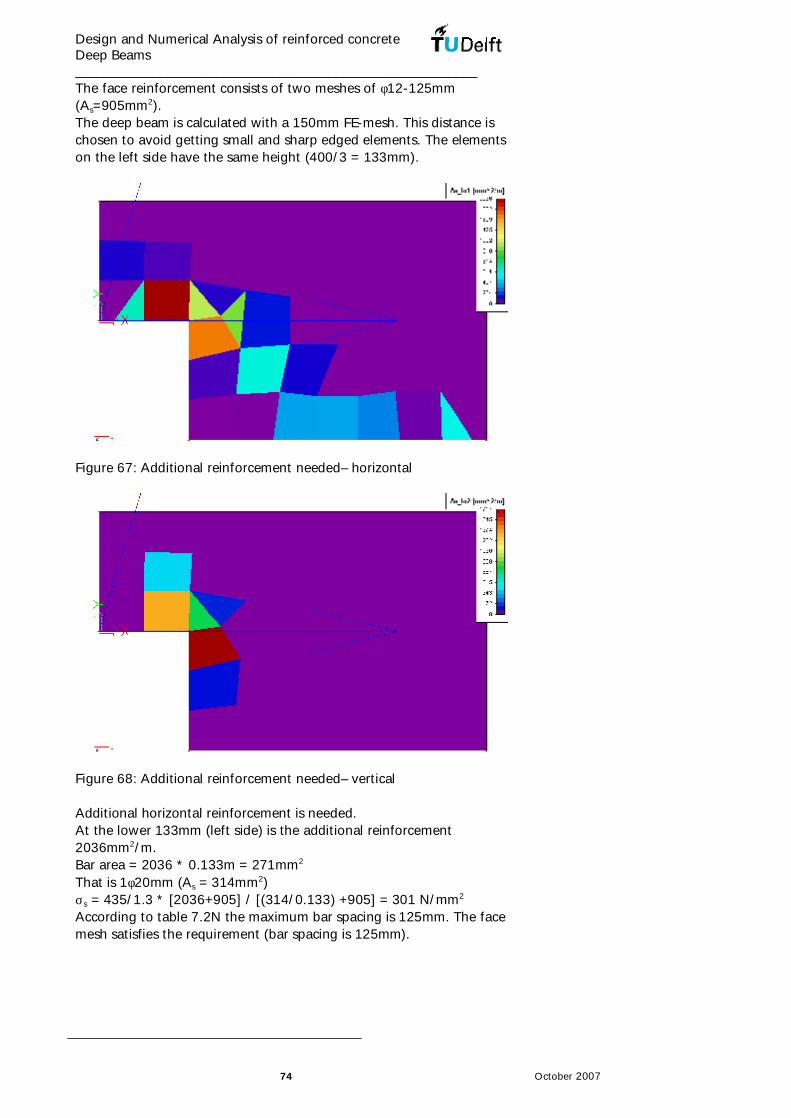
Design and Numerical Analysis of reinforced concrete Deep Beams _________________________________________________________
74 October 2007
The face reinforcement consists of two meshes of φ12-125mm (As=905mm2). The deep beam is calculated with a 150mm FE-mesh. This distance is chosen to avoid getting small and sharp edged elements. The elements on the left side have the same height (400/3 = 133mm).
Figure 67: Additional reinforcement needed– horizontal
Figure 68: Additional reinforcement needed– vertical Additional horizontal reinforcement is needed. At the lower 133mm (left side) is the additional reinforcement 2036mm2/m. Bar area = 2036 * 0.133m = 271mm2 That is 1φ20mm (As = 314mm2) σs = 435/1.3 * [2036+905] / [(314/0.133) +905] = 301 N/mm2 According to table 7.2N the maximum bar spacing is 125mm. The face mesh satisfies the requirement (bar spacing is 125mm).

Design and Numerical Analysis of reinforced concrete Deep Beams _________________________________________________________
75 October 2007
In the second left element (133mm) is the additional reinforcement 85mm2/m. Bar area = 85 * 0.133m = 11mm2 That is 1φ8mm (As = 50mm2) σs = 435/1.3 * [85+905] / [(50/0.133) +905] = 259 N/mm2 According to table 7.2N the maximum bar spacing is 175mm. The face mesh satisfies the requirement (bar spacing is 125mm). In the lower element (150mm) is the additional reinforcement 576mm2/m. Bar area = 576 * 0.15m = 87mm2 That is 1φ12mm (As = 113mm2) σs = 435/1.3 * [576+905] / [(113/0.15) +905] = 299 N/mm2 According to table 7.2N the maximum bar spacing is 125mm. The face mesh satisfies the requirement (bar spacing is 125mm). Additional vertical reinforcement is needed. At the small left side 150mm is the additional reinforcement 1342mm2/m. Bar area = 1342 * 0.150m = 201mm2 That is 2φ12mm (As = 226mm2) σs = 435/1.3 * [1342+905] / [(226/0.150) +905] = 312N/mm2 According to table 7.2N the maximum bar spacing is 100mm. The face mesh with the extra bars satisfies the requirement (bar spacing is 125/2 = 62mm). In the tall left element (150mm) is the additional reinforcement 1717mm2/m. Bar area = 1717 * 0.150m = 258mm2 That is 2φ16mm (As = 402mm2) σs = 435/1.3 * [1717+905] / [(402/0.150) +905] = 245 N/mm2 According to table 7.2N the maximum bar spacing is 180mm. The face mesh satisfies the requirement (bar spacing is 125mm).
φ16
φ20
φ8
φ16
φ12
φ12-125mm
φ12-12
5mm
φ16
φ12
φ12
φ12
φ12-125mm
φ16
φ12
φ12
φ20
φ8
Α
Α
Sec. A-A
φ16
φ16
Figure 69: The reinforcement

Design and Numerical Analysis of reinforced concrete Deep Beams _________________________________________________________
76 October 2007
The crack width satisfies the requirement of environment class XC4, 0.30mm according to table 7.3N. The weight of the used reinforcement in this member is about 0.432kN. Case 3: This wall with an opening in the middle is loaded with one concentrated load, which does not lie in the middle. The length of both supports is 100mm and of the load is 200mm. The face reinforcement consists of two meshes of φ8-150mm (As=335mm2). This reinforcement is higher than the minimum reinforcement, but it is needed according to ESA. More reinforcement is needed in both directions (vertical and horizontal), 13mm2/m, in bigger area of the beam, but the choice was to use a practical bar spacing. The deep beam is calculated with a 250mm FE-mesh. This distance is chosen to avoid getting too big concentrated stresses in a small element.
Figure 70: Additional reinforcement needed– horizontal
Figure 71: Additional reinforcement needed– vertical

Design and Numerical Analysis of reinforced concrete Deep Beams _________________________________________________________
77 October 2007
Additional horizontal reinforcement is needed. At the left upper side of the opening (in the middle) is the additional reinforcement 1548mm2/m. Bar area = 1548 * 0.250m = 387mm2 That is 2φ20mm (As = 628mm2) σs = 435/1.3 * [1548+335] / [(628/0.250) +335] = 221 N/mm2 According to table 7.2N the maximum bar spacing is 225mm. The face mesh satisfies the requirement (bar spacing is 150mm). In the second element (250mm) is the additional reinforcement 589mm2/m. Bar area = 589 * 0.250m = 147mm2 That is 1φ16mm (As = 201mm2) σs = 435/1.3 * [589+335] / [(201/0.250) +335] = 271 N/mm2 According to table 7.2N the maximum bar spacing is 155mm. The face mesh satisfies the requirement (bar spacing is 150mm). In the lower element by the support (250mm) is the additional reinforcement 237mm2/m. Bar area = 237 * 0.25m = 59mm2 That is 1φ12mm (As = 113mm2) σs = 435/1.3 * [237+335] / [(113/0.25) +335] = 243 N/mm2 According to table 7.2N the maximum bar spacing is 200mm. The face mesh satisfies the requirement (bar spacing is 150mm). Additional vertical reinforcement is needed. At the tall left side of the opening (250mm) is the additional reinforcement 662mm2/m. Bar area = 662 * 0.250m = 166mm2 That is 2φ12mm (As = 226mm2) σs = 435/1.3 * [662+335] / [(226/0.250) +335] = 269N/mm2 According to table 7.2N the maximum bar spacing is 155mm. The face mesh satisfies the requirement (bar spacing is 150mm). In the short left side of the opening (250mm) is the additional reinforcement 419mm2/m. Bar area = 419 * 0.250m = 105mm2 That is 2φ10mm (As = 157mm2) σs = 435/1.3 * [419+335] / [(157/0.250) +335] = 262 N/mm2 According to table 7.2N the maximum bar spacing is 160mm. The face mesh satisfies the requirement (bar spacing is 150mm). At the tall right side of the opening (250mm) is the additional reinforcement 167mm2/m. Bar area = 167 * 0.250m = 42mm2 That is 1φ12mm (As = 113mm2) σs = 435/1.3 * [167+335] / [(113/0.250) +335] = 213N/mm2 According to table 7.2N the maximum bar spacing is 230mm. The face mesh satisfies the requirement (bar spacing is 150mm). This symmetric shape is loaded with asymmetric load. Due to economical reasons, the construction was not symmetric reinforced.

Design and Numerical Analysis of reinforced concrete Deep Beams _________________________________________________________
78 October 2007
The loaded side gets more reinforcement than the other side. Practically, this side must be clearly marked to avoid mistakes by using the member in the wrong direction.
Sec. A-A
φ8-150
φ12
φ20
φ16
φ12
φ8-150
φ8-15
0
φ20φ20
φ12
φ12
φ12
φ10
φ10
φ12
φ12
φ16
φ12
Figure 72: The reinforcement The crack width satisfies the requirement of environment class XC4, 0.30mm according to table 7.3N. The weight of the used reinforcement in this member is about 2.619kN. Case 4: A wall with an opening in the middle is the best description of this deep beam. The length of both supports is 100mm and of the load is 200mm. The face reinforcement consists of two meshes of φ10-140mm (As=561mm2). This reinforcement is higher than the minimum reinforcement, but it is needed according to ESA. More reinforcement is needed in both directions (vertical and horizontal), 12mm2/m, in bigger area of the beam, but the choice was to use a practical bar spacing. The deep beam is calculated with a 200mm FE-mesh.

Design and Numerical Analysis of reinforced concrete Deep Beams _________________________________________________________
79 October 2007
Figure 73: Additional reinforcement needed– horizontal
Figure 74: Additional reinforcement needed– vertical Additional horizontal reinforcement is needed. At the upper left side of the opening is the additional reinforcement 538mm2/m. Bar area = 538 * 0.20m = 108mm2 That is 1φ16mm (As = 201mm2) σs = 435/1.3 * [538+561] / [(201/0.20) +561] = 235 N/mm2 According to table 7.2N the maximum bar spacing is 200mm. The face mesh satisfies the requirement (bar spacing is 140mm). In the lower right side of the opening is the additional reinforcement 691mm2/m. Bar area = 691 * 0.20m = 138mm2 That is 1φ16mm (As = 201mm2) σs = 435/1.3 * [691+561] / [(201/0.20) +561] = 268 N/mm2

Design and Numerical Analysis of reinforced concrete Deep Beams _________________________________________________________
80 October 2007
According to table 7.2N the maximum bar spacing is 155mm. The face mesh satisfies the requirement (bar spacing is 140mm). In the lower element by the support (200mm) is the additional reinforcement 437mm2/m. Bar area = 437 * 0.20m = 87mm2 That is 1φ16mm (As = 201mm2) σs = 435/1.3 * [437+561] / [(201/0.20) +561] = 213 N/mm2 According to table 7.2N the maximum bar spacing is 225mm. The face mesh satisfies the requirement (bar spacing is 140mm). Additional vertical reinforcement is needed. At the tall right side of the opening (200mm) is the additional reinforcement 453mm2/m. Bar area = 453 * 0.20m = 91mm2 That is 1φ16mm (As = 201mm2) σs = 435/1.3 * [453+561] / [(201/0.20) +561] = 217 N/mm2 According to table 7.2N the maximum bar spacing is 225mm. The face mesh satisfies the requirement (bar spacing is 140mm).
Sec. A-A
φ16
φ16
φ10-140
φ12
φ10-140
φ16
φ16
φ16
φ10-
140
φ10-140
φ16
φ12
φ12
Figure 75: The reinforcement The crack width satisfies the requirement of environment class XC4, 0.30mm according to table 7.3N. The weight of the used reinforcement in this member is about 4.500kN.

Design and Numerical Analysis of reinforced concrete Deep Beams _________________________________________________________
81 October 2007
Case 5: In this case the deep beam does not have any opening and is loaded with a uniformly distributed load. The support length is 100mm. The face reinforcement consists of two meshes of φ8-160mm (As=314mm2). This reinforcement is higher than the minimum reinforcement, but it is needed according to ESA. More reinforcement is needed in both directions (vertical and horizontal), 4mm2/m, in bigger area of the beam, but the choice was to use a practical bar spacing. The deep beam is calculated with a 100mm FE-mesh.
Figure 76: Additional reinforcement needed– horizontal
Figure 77: Additional reinforcement needed– vertical No additional reinforcement is needed. Only one element on the left support needs extra reinforcement, and it is considered to be due to calculation effects. Nevertheless it was calculated below:

Design and Numerical Analysis of reinforced concrete Deep Beams _________________________________________________________
82 October 2007
Additional horizontal reinforcement: At the lower edge on the left support is the additional reinforcement 112mm2/m. Bar area = 112 * 0.10m = 11mm2 That is 1φ6mm (As = 28mm2) σs = 435/1.3 * [112+314] / [(28/0.10) +314] = 240 N/mm2 According to table 7.2N the maximum bar spacing is 200mm. The face mesh satisfies the requirement (bar spacing is 160mm).
Sec. A-A
φ8-160
φ6
φ8-160
φ6
φ8-16
0
Figure 78: The reinforcement The crack width satisfies the requirement of environment class XC4, 0.30mm according to table 7.3N. The weight of the used reinforcement in this member is about 1.492kN. Case 6: The shape of this deep beam is similar to a façade of a building. The thickness of the beam (150mm) is also suitable for such construction. The load is uniformly distributed and is rather small (5kN/m in SLS). The face reinforcement consists of two meshes of φ6-150mm (As=188mm2). This reinforcement is higher than the minimum reinforcement, but it is chosen as a practical reinforcement. The deep beam is calculated with a 100mm FE-mesh.

Design and Numerical Analysis of reinforced concrete Deep Beams _________________________________________________________
83 October 2007
Figure 79: Additional reinforcement needed– horizontal
Figure 80: Additional reinforcement needed– vertical

Design and Numerical Analysis of reinforced concrete Deep Beams _________________________________________________________
84 October 2007
Figure 81: Total reinforcement needed – vertical Additional vertical reinforcement is needed. At the lower left side of the structure is the additional reinforcement 7mm2/m. Bar area = 7 * 0.10m = 1mm2 That is 1φ6mm (As = 28mm2) σs = 435/1.3 * [7+314] / [(28/0.10) +314] = 181 N/mm2 According to table 7.2N the maximum bar spacing is 275mm. The face mesh satisfies the requirement (bar spacing is 150mm).

Design and Numerical Analysis of reinforced concrete Deep Beams _________________________________________________________
85 October 2007
Sec. A-A
φ6-150
φ6
φ6-15
0
φ6-150
φ6 φ6
φ6
φ6φ6
φ6
φ6
Figure 82: The reinforcement The crack width satisfies the requirement of environment class XC4, 0.30mm according to table 7.3N. The weight of the used reinforcement in this member is about 1.174kN. Case 7: In this case the deep beam does not have any opening and is loaded with a uniformly distributed load. The support length is 100mm. The face reinforcement consists of two meshes of φ8-200mm (As=251mm2). This reinforcement is higher than the minimum reinforcement, but it is needed according to ESA. The deep beam is calculated with a 100mm FE-mesh.
Figure 83: Additional reinforcement needed– horizontal

Design and Numerical Analysis of reinforced concrete Deep Beams _________________________________________________________
86 October 2007
Figure 84: Additional reinforcement needed– vertical Additional horizontal reinforcement is needed. At the lower edge of the beam is the additional reinforcement 182mm2/m. Bar area = 182 * 0.10m = 18mm2 That is 1φ8mm (As = 50mm2) σs = 435/1.3 * [182+251] / [(50/0.10) +251] = 193 N/mm2 According to table 7.2N the maximum bar spacing is 250mm. The horizontal face mesh satisfies the requirement (bar spacing is 200mm). No additional vertical reinforcement is needed.
Sec. A-A
φ8-200
φ8
φ8-200
φ8-200
φ8
Figure 85: The reinforcement

Design and Numerical Analysis of reinforced concrete Deep Beams _________________________________________________________
87 October 2007
The crack width satisfies the requirement of environment class XC4, 0.30mm according to table 7.3N. The weight of the used reinforcement in this member is about 1.239kN. Case 8: This case is similar to a corbel with a circular opening. The face reinforcement in the figures below consists of two meshes of φ8-127mm (As=396mm2). This reinforcement is higher than the minimum reinforcement, but it is needed according to ESA. More reinforcement is needed in both directions (vertical and horizontal), 28mm2/m, in bigger area of the beam. The definitive choice is φ8-120mm (As=419mm2). The deep beam is calculated with a 100mm FE-mesh.
Figure 86: Additional reinforcement needed– horizontal
Figure 87: Additional reinforcement needed– vertical

Design and Numerical Analysis of reinforced concrete Deep Beams _________________________________________________________
88 October 2007
Additional horizontal reinforcement is needed. At the upper left side of the beam is the additional reinforcement 286mm2/m. Bar area = 286 * 0.10m = 29mm2 That is 1φ8mm (As = 50mm2) σs = 435/1.3 * [286+419] / [(50/0.10) +419] = 257 N/mm2 According to table 7.2N the maximum bar spacing is 175mm. The face mesh satisfies the requirement (bar spacing is 120mm). No additional vertical reinforcement is needed.
Sec. A-A
φ8-120
φ8
φ8-12
0
φ8-120
φ8
Figure 88: The reinforcement The crack width satisfies the requirement of environment class XC4, 0.30mm according to table 7.3N. The weight of the used reinforcement in this member is about 1.411kN. Case 9: The support plate length is 100mm and the load plate length is 200mm. The face reinforcement in the figures below consists of φ8-150mm (As=335mm2). The reinforcement is higher than the minimum reinforcement, but it is needed according to ESA. The deep beam is calculated with a 100mm FE-mesh.

Design and Numerical Analysis of reinforced concrete Deep Beams _________________________________________________________
89 October 2007
Figure 89: Additional reinforcement needed– horizontal
Figure 90: Additional reinforcement needed– vertical Additional horizontal reinforcement is needed. At the lower edge of the beam is the additional reinforcement 213mm2/m. Bar area = 213 * 0.10m = 21mm2 That is 1φ8mm (As = 50mm2) σs = 435/1.3 * [213+561] / [(50/0.10) +561] = 244 N/mm2

Design and Numerical Analysis of reinforced concrete Deep Beams _________________________________________________________
90 October 2007
According to table 7.2N the maximum bar spacing is 200mm. The face mesh satisfies the requirement (bar spacing is 200mm). No additional vertical reinforcement is needed.
φ8
φ8-150
Sec. A-A
φ8-15
0
φ8-150
φ8
Figure 91: The reinforcement The crack width satisfies the requirement of environment class XC4, 0.30mm according to table 7.3N. The weight of the used reinforcement in this member is about 1.274kN. Case 10: The support plate length is 100mm and he is loaded with a uniformly distributed load. The face reinforcement in the figures below consists of two meshes of φ8-200mm (As=251mm2). The deep beam is calculated with a 100mm FE-mesh.

Design and Numerical Analysis of reinforced concrete Deep Beams _________________________________________________________
91 October 2007
Figure 92: Additional reinforcement needed– horizontal
Figure 93: Additional reinforcement needed– vertical Additional horizontal reinforcement is needed. Only at the edges of the middle half of the beam height is the additional reinforcement 48mm2/m. Bar area = 48 * 0.20m = 10mm2 That is 1φ6mm (As = 28mm2)

Design and Numerical Analysis of reinforced concrete Deep Beams _________________________________________________________
92 October 2007
σs = 435/1.3 * [48+251] / [(28/0.20) +251] = 260 N/mm2 According to table 7.2N the maximum bar spacing is 175mm. The face mesh and the extra horizontal mesh of φ6-200mm satisfy the requirement (bar spacing is 100mm). At the lower quarter of the beam height is the additional reinforcement 97mm2/m. Bar area = 97 * 0.20m = 20mm2 That is 1φ6mm (As = 28mm2) σs = 435/1.3 * [97+251] / [(28/0.20) +251] = 302 N/mm2 According to table 7.2N the maximum bar spacing is 120mm. The face mesh and the extra horizontal mesh of φ6-200mm satisfy the requirement (bar spacing is 100mm). At the lower edge of the beam is the additional reinforcement (208-97)mm2/m. Bar area = (208-97) * 0.20m = 22mm2 That is 1φ8mm (As = 50mm2) σs = 435/1.3 * [97+251] / [(50/0.20) +251] = 232 N/mm2 According to table 7.2N the maximum bar spacing is 200mm. The face mesh and the extra horizontal mesh of φ6-200mm satisfy the requirement (bar spacing is 100mm). Additional vertical reinforcement is needed. At the lower quarter of the beam height is the additional reinforcement 97mm2/m. Bar area = 97 * 0.20m = 20mm2 That is 1φ6mm (As = 28mm2) σs = 435/1.3 * [97+251] / [(28/0.2) +251] = 302 N/mm2 According to table 7.2N the maximum bar spacing is 120mm. The face mesh and the extra vertical mesh of (φ6-200mm) satisfy the requirement (bar spacing is 200/2=100mm).

Design and Numerical Analysis of reinforced concrete Deep Beams _________________________________________________________
93 October 2007
φ8
φ8-200
φ6-200
Sec. A-A
φ8-200
φ8-200
φ8
φ6-200
φ6-200 φ6-200
φ6-200
Figure 94: The reinforcement The crack width satisfies the requirement of environment class XC4, 0.30mm according to table 7.3N. The weight of the used reinforcement in this member is about 1.181kN. Case 11: This famous shape is the only statically indeterminate case in this study. The length of the support plates at the sides is 100mm, in the middle is 200mm and the load plate length is 200mm. The face reinforcement in the figures below consists of two meshes of φ8-150mm (As=335mm2). That is more than the minimum reinforcement according to the Eurocode, but it is needed according to ESA calculations. The deep beam is calculated with a 100mm FE-mesh.

Design and Numerical Analysis of reinforced concrete Deep Beams _________________________________________________________
94 October 2007
Figure 95: Additional reinforcement needed– horizontal
Figure 96: Additional reinforcement needed– vertical Additional horizontal reinforcement is needed. At the lower edge of the beam is the additional reinforcement 390mm2/m. Bar area = 390 * 0.10m = 39mm2 That is 1φ10mm (As = 79mm2) σs = 435/1.3 * [390+335] / [(79/0.10) +335] = 216 N/mm2 According to table 7.2N the maximum bar spacing is 230mm. The face mesh satisfies the requirement (bar spacing is 150mm). No additional vertical reinforcement is needed.

Design and Numerical Analysis of reinforced concrete Deep Beams _________________________________________________________
95 October 2007
φ10
φ8-200
φ6
φ6
Sec. A-A
φ8-150
φ8-15
0
φ10φ6
φ6
Figure 97: The reinforcement The crack width satisfies the requirement of environment class XC4, 0.30mm according to table 7.3N. The weight of the used reinforcement in this member is about 0.896kN.
5.4 Remarks
ESA Prima Win is the preceding program of ESA-PT. The new ESA-PT is not only able to model plates and lines, respectively 1D and 2D elements and connecting them in 3D structures, but also able to model the details and connections between the elements. Using this program, which can used to calculate complete structures, for just a deep beam should not be a problem, but it was not easy to find the way in this big program. It is not clear where the user missed the use of an existing ability of the program or he/she is looking for something not included yet in the program. For example, adding extra reinforcement bars by the opening in a plate is not yet included. It is also not clear if the user should make his/her choice or the program itself knows what it should do. For example, the user should choose to activate the structural reinforcement of deep beam. Finding a bug in the program in a small calculation was also not expected. In the used version of the program (the last version, July 2007), when a plate has been calculated in 2D mode, the program recognises only one reinforcement mesh, while the program offers to calculate many layers of reinforcement meshes. The developer of ESA, SCIA, promised to solve this problem. Because of some limitations in the program the user cannot benefit from complete options in the program. For example, the crack width

Design and Numerical Analysis of reinforced concrete Deep Beams _________________________________________________________
96 October 2007
control is one of the existing options of ESA-PT but it cannot be used because there is no option to add additional bars with the mesh reinforcements. The program shows that the beam needs more mesh reinforcement and less concentrated (tie) reinforcement. The reason is unknown. It seams that the mesh reinforcement is not only related to the big compression stresses in the struts. It is not possible now to check the results with hand-calculations.

Design and Numerical Analysis of reinforced concrete Deep Beams _________________________________________________________
97 October 2007
6. Finite element method (non-linear)
6.1 Introduction
In this chapter the calculation of each element according the Strut-and-Tie Method, the Beam Method and according the Linear Finite Element Method (ESA-PT) will be checked using a Non-Linear Finite Element Method program (Atena) (FNL-FEM). The calculation (FNL-FEM) in this program (Atena) is done to simulate the real designed elements in all details, such as the dimensions of the load- and support plates, development length, the number and location of bars and the concrete cover. Atena has default settings for concrete, reinforcement and reinforcement bond. In the calculations made, these default settings were used because in this research no laboratories tests were done and therefore no exact values can be established. Concrete properties: (Atena)
fck fck,cube fcm fctm µ wd* Ecm
30 37 31.45 2.66 0.2 -0.5 33010 Table 2: Default settings for concrete (Atena) *) Critical compressive displacement (m) Reinforcement properties: (Atena)
σy Ecm
435 210000 Table 3: Default settings for reinforcement (Atena) Reinforcement bond properties: (Atena)
Bond stress Slip
4.8425 MPa 0.0 Table 4: Default settings for reinforcement bond (Atena) In the program, steps can be used to simulate loading stages. Each structural element has been calculated with ultimate strength of the steel and concrete without any (material) factors, and the load used is the load in the serviceability limit state (SLS). The steps of the program are used to increase the load gradually in order to get more accurate results. The load is divided into ten parts, and calculated in ten steps. At the end of the tenth step the results will be similar to the results of the SLS. Extra steps are calculated to study the reaction of the elements. At the end of step thirteen the results can be compared to the results of the ultimate limit state (ULS). The safety factor is 1,305 as shown before.

Design and Numerical Analysis of reinforced concrete Deep Beams _________________________________________________________
98 October 2007
As mentioned above, the strength of the reinforcement and the concrete used is without any factors. Therefore, the stresses in the reinforcement and the concrete in the ULS should be checked manually. In all cases, more calculation steps were computed to test the safety remaining and to check in which way the failure will occur. Not in all cases the failure has been reached, in these cases, the calculation is finished at a certain point. The results of the calculation will be listed below. The tables give the results of the SLS (step 10 of the calculation) and the ULS (step 13 of the calculation), and the figures show the failure state of the elements.
6.2 Study cases
Case 1: The deep beam was calculated three times, once with the design according to the strut-and-tie model, other according to the beam method and the last with L-FEM. The stress flow in the beam can be seen clearly. But the maximum crack width took place along the struts and not across the tie. Looking at the direction of the cracks it is obvious that the compression stresses at the edges of the steel plates is concentrated and that leads to the splitting cracks. The stress in the mesh reinforcement is not given in the results of the program. This concentration of stresses at the edges of the steel plates has also caused a change in the angle between the struts and the tie. This angle became bigger and the stress in the tie became smaller. The ends of the reinforcement bars are fixed and therefore the stress at these ends is not zero. In the design the bars are welded to steel plates. Strut-and-tie Beam Method L-FEM Step 10 (SLS) crack width (mm)
0.24 Satisfy 0.59 Not satisfy
0.28 Satisfy
Step 13 (ULS) bar stress (N/mm2)
190 Satisfy 198 Satisfy 330 Satisfy
Table 5: Results of Atena Calculations (Case 1)

Design and Numerical Analysis of reinforced concrete Deep Beams _________________________________________________________
99 October 2007
Step 15, Case1 Scalars:iso-areas, Basic material, in nodes, Stress, Sigma yy, <-3.082E+01;1.076E+00>[MPa] Cracks: in elements, openning: <2.465E-06;3.533E-04>[m], Sigma_n: <0.000E+00;2.290E+00>[MPa], Sigma_T : <-1.519E+00;1.168E+00>[MPa] Reinforcements: Stress, Sigma xx, <2.712E+01;2.247E+02>[MPa]
X
Y
-3.082E+01-3.000E+01-2.700E+01-2.400E+01-2.100E+01-1.800E+01-1.500E+01-1.200E+01-9.000E+00-6.000E+00-3.000E+000.000E+001.076E+00
Figure 98: Failure of STM Step 15, Case1 Scalars:iso-areas, Basic material, in nodes, Stress, Sigma yy, <-1.943E+01;1.359E+00>[MPa] Cracks: in elements, openning: <1.808E-05;9.215E-04>[m], Sigma_n: <0.000E+00;8.852E-01>[MPa], Sigma_T : <-1.665E+00;1.022E+00>[MPa] Reinforcements: Stress, Sigma xx, <-6.535E+01;2.305E+02>[MPa]
X
Y
-1.943E+01-1.800E+01-1.600E+01-1.400E+01-1.200E+01-1.000E+01-8.000E+00-6.000E+00-4.000E+00-2.000E+000.000E+001.359E+00
Figure 99: Failure of Beam Method

Design and Numerical Analysis of reinforced concrete Deep Beams _________________________________________________________
100 October 2007
Step 15, Case1 Scalars:iso-areas, Basic material, in nodes, Stress, Sigma yy, <-3.101E+01;1.143E+00>[MPa] Cracks: in elements, openning: <-2.941E-04;5.679E-04>[m], Sigma_n: <-7.800E+00;5.665E+00>[MPa], Sigma_T : <-2.665E+00;2.665E+00>[MPa] Reinforcements: Stress, Sigma xx, <2.909E+00;4.350E+02>[MPa]
X
Y
-3.101E+01-1.500E+01-1.350E+01-1.200E+01-1.050E+01-9.000E+00-7.500E+00-6.000E+00-4.500E+00-3.000E+00-1.500E+000.000E+001.143E+00
Figure 100: Failure of L-FEM The mesh reinforcement in the Beam Method has big c-to-c distance, comparing it to the dimension of the structural element. Therefore, it is calculated as bars. The effect of the bars on the cracks is not clear, because the cracks are calculated in the generated mesh of the element. Especially for the Beam Method, because of the relative big mesh, a small deference in the calculation will lead to a notable change in the results. Therefore, the results are not symmetrical. Case 2: The deep beam was calculated three times, once with the design according to the strut-and-tie model, other according to the beam method and the last with L-FEM. The stress flow in the beam can be seen clearly. The maximum crack width took place at the point of height change, where expected. The ends of the reinforcement bars are fixed and therefore the stress at these ends is not zero. In the design the bars are bent in the horizontal direction. Strut-and-tie Beam Method L-FEM Step 10 (SLS) crack width (mm)
0.15 Satisfy 0.29 Satisfy 0.42 Not satisfy
Step 13 (ULS) bar stress (N/mm2)
118 Satisfy 257 Satisfy 291 Satisfy
Table 6: Results of Atena Calculations (Case 2)

Design and Numerical Analysis of reinforced concrete Deep Beams _________________________________________________________
101 October 2007
Step 15, Case2 Scalars:iso-areas, Basic material, in nodes, Stress, Sigma yy, <-3.178E+01;2.966E+00>[MPa] Cracks: in elements, openning: <3.380E-05;2.914E-04>[m], Sigma_n: <0.000E+00;7.476E-01>[MPa], Sigma_T : <-3.320E-01;5.603E-01>[MPa] Reinforcements: Stress, Sigma xx, <-1.024E+00;1.527E+02>[MPa]
X
Y
-3.178E+01-6.400E+00-5.600E+00-4.800E+00-4.000E+00-3.200E+00-2.400E+00-1.600E+00-8.000E-010.000E+008.000E-011.600E+002.966E+00
Figure 101: Failure of STM Step 15, Case2 Scalars:iso-areas, Basic material, in nodes, Stress, Sigma yy, <-3.167E+01;2.824E+00>[MPa] Cracks: in elements, openning: <2.070E-06;4.861E-04>[m], Sigma_n: <0.000E+00;1.145E+00>[MPa], Sigma_T : <-5.701E-01;1.340E+00>[MPa] Reinforcements: Stress, Sigma xx, <-3.585E+01;2.950E+02>[MPa]
X
Y
-3.167E+01-6.400E+00-5.600E+00-4.800E+00-4.000E+00-3.200E+00-2.400E+00-1.600E+00-8.000E-010.000E+008.000E-011.600E+002.824E+00
Figure 102: Failure of Beam Method

Design and Numerical Analysis of reinforced concrete Deep Beams _________________________________________________________
102 October 2007
Step 15, Case2 Scalars:iso-areas, Basic material, in nodes, Stress, Sigma yy, <-3.178E+01;3.273E+00>[MPa] Cracks: in elements, openning: <2.613E-05;8.276E-04>[m], Sigma_n: <0.000E+00;7.588E-01>[MPa], Sigma_T : <-8.282E-01;1.414E+00>[MPa] Reinforcements: Stress, Sigma xx, <-8.096E+00;3.427E+02>[MPa]
X
Y
-3.178E+01-4.550E+00-3.900E+00-3.250E+00-2.600E+00-1.950E+00-1.300E+00-6.500E-010.000E+006.500E-011.300E+003.273E+00
Figure 103: Failure of L-FEM The extra mesh reinforcement in the Beam Method is calculated as bars. The effect of the bars on the cracks is not clear, because the cracks are calculated in the generated mesh of the element. Because of the extra mesh reinforcement of the Beam Method, smaller elements are used in the calculation, and that led to finer cracks. As shown in the results of the L-FEM the crack width does not satisfy the requirements of the code. Maybe that comes because of the rather large elements in the calculations, 150mm for the L-FEM and 125mm for the Non-linear Finite Element Method (FNL-FEM). Case 3: The deep beam was calculated four times, once with the design according to the strut-and-tie model, two others according to the beam method as mentioned before and the last with L-FEM. The stress flow in the beam can be seen clearly. But the maximum crack width at the failure stage took place in different places. The first cracks occurred in the expected place in de small part at location of different depth of the beam. This concentration of horizontal stresses at the main reinforcement (short bars) of the Beam Method caused an unexpected failure. The development length (ld) of the bars in the design is according the calculations, but with the understanding of stress distribution the stresses as it in the strut-and-tie model shows that the tension in the main reinforcement will not disappear in the concrete mass as expected. Although the Beam Method did not give any recommendation about this case, another calculation was done with one adjustment, which is longer main reinforcement.

Design and Numerical Analysis of reinforced concrete Deep Beams _________________________________________________________
103 October 2007
The results of the strut-and-tie method and the L-FEM are close to each other. Strut-and-tie Beam Method L-FEM Step 10 (SLS) crack width (mm)
0.25 Satisfy 0.75 Not satisfy
0.25 Satisfy
Step 13 (ULS) bar stress (N/mm2)
171 Satisfy 206 Satisfy 221 Satisfy
Table 7: Results of Atena Calculations (Case 3) Case 3a Beam Method Step 10 Crack width (SLS) 0.75 mm Not satisfy Step 13 Bar stress (ULS) 207 N/mm2 Satisfy Table 8: Results of Atena Calculations (Case 3a) Step 15, Case3 Scalars:iso-areas, Basic material, in nodes, Stress, Sigma yy, <-4.546E+01;3.015E+00>[MPa] Cracks: in elements, openning: <2.845E-06;4.375E-04>[m], Sigma_n: <0.000E+00;1.639E+00>[MPa], Sigma_T : <-2.952E-01;5.066E-01>[MPa] Reinforcements: Stress, Sigma xx, <-3.559E+01;2.015E+02>[MPa]
X
Y
-4.546E+01-6.400E+00-5.600E+00-4.800E+00-4.000E+00-3.200E+00-2.400E+00-1.600E+00-8.000E-010.000E+008.000E-011.600E+003.015E+00
Figure 104: Failure of STM Step 15, Case3 Scalars:iso-areas, Basic material, in nodes, Stress, Sigma yy, <-4.499E+01;3.490E+00>[MPa] Cracks: in elements, openning: <3.090E-06;1.264E-03>[m], Sigma_n: <0.000E+00;1.623E+00>[MPa], Sigma_T : <-1.090E+00;8.923E-01>[MPa] Reinforcements: Stress, Sigma xx, <-3.101E+01;2.438E+02>[MPa]
X
Y
-4.499E+00-3.900E+00-3.250E+00-2.600E+00-1.950E+00-1.300E+00-6.500E-010.000E+006.500E-011.300E+001.950E+002.600E+003.250E+003.490E+00
Figure 105: Failure of Beam Method (Case 3)

Design and Numerical Analysis of reinforced concrete Deep Beams _________________________________________________________
104 October 2007
Step 15, Case3a Scalars:iso-areas, Basic material, in nodes, Stress, Sigma yy, <-4.500E+01;3.471E+00>[MPa] Cracks: in elements, openning: <3.080E-06;1.093E-03>[m], Sigma_n: <0.000E+00;1.624E+00>[MPa], Sigma_T : <-5.550E-01;8.999E-01>[MPa] Reinforcements: Stress, Sigma xx, <-3.097E+01;2.372E+02>[MPa]
X
Y
-4.500E+01-2.500E+00-2.000E+00-1.500E+00-1.000E+00-5.000E-010.000E+005.000E-011.000E+001.500E+002.000E+003.471E+00
Figure 106: Failure of Beam Method (case 3a) Step 15, Case3 Scalars:iso-areas, Basic material, in nodes, Stress, Sigma yy, <-4.555E+01;3.357E+00>[MPa] Cracks: in elements, openning: <1.375E-06;5.143E-04>[m], Sigma_n: <0.000E+00;1.613E+00>[MPa], Sigma_T : <-4.836E-01;9.355E-01>[MPa] Reinforcements: Stress, Sigma xx, <-4.128E+01;2.743E+02>[MPa]
X
Y
-4.555E+01-5.600E+00-4.900E+00-4.200E+00-3.500E+00-2.800E+00-2.100E+00-1.400E+00-7.000E-010.000E+007.000E-011.400E+003.357E+00
Figure 107: Failure of L-FEM The mesh reinforcement in the Beam Method has a bigger c-to-c distance (300mm), compared to that of the L-FEM (150mm) and of the strut-and-tie model (200mm). This deference is rather small. The effect of the bars on the cracks is not clear, because the cracks are calculated in the generated mesh of the element, and not in the reinforcement mesh. Case 4: As mentioned before, this deep beam was calculated three times, once with the design according to the strut-and-tie model, other according to the beam method and the last with L-FEM. A second strut-and-tie model calculation has been done because the cracks in the first design occur in an unexpected location. The danger

Design and Numerical Analysis of reinforced concrete Deep Beams _________________________________________________________
105 October 2007
of the unexpected location is that this location has absolutely no main reinforcement. In the second design more bars were used in the model to check the stresses and forces in the concrete mass. Of course any change in the location of the bars will lead to a change in the force distribution, therefore adding bars dose not always result in a better design, but in this case this change (adding bars) was necessary to avoid wide cracks in that certain location. The force distribution became much better in the second design; high stress concentrations disappear and tension forces went through reinforcement bars. The beam calculated according to the Beam Method has cracked in three places. As expected, the Beam method is not the best method to design this beam, because the stiffness of the upper concrete part will have a big effect on the deformation of the element. Considering the upper part only as dead load is far from reality, and the effect of this upper part would not be limited to cracks in the upper part, but also in affecting the rest of the beam (load-carrying lower part). There will be now no adjustment for the design, because the Beam Method did not give any recommendation about this situation. Strut-and-tie Beam Method L-FEM Step 10 (SLS) crack width (mm)
0.03 Satisfy 0.0 Satisfy 0.0 Satisfy
Step 13 (ULS) bar stress (N/mm2)
24 Satisfy 13 Satisfy 70 Satisfy
Table 9: Results of Atena Calculations (Case 4) Case 4a Strut-and-tie Step 10 Crack width (SLS) 0.0 mm Satisfy Step 13 Bar stress (ULS) 38 N/mm2 Satisfy Table 10: Results of Atena Calculations (Case 4a) Step 25, Case4 Scalars:iso-areas, Basic material, in nodes, Stress, Sigma yy, <-7.166E+01;4.040E+00>[MPa] Cracks: in elements, openning: <5.346E-06;1.424E-03>[m], Sigma_n: <0.000E+00;1.154E+00>[MPa], Sigma_T : <-8.910E-01;7.225E-01>[MPa] Reinforcements: Stress, Sigma xx, <-1.169E+02;1.676E+02>[MPa]
X
Y
-7.166E+01-6.300E+00-5.600E+00-4.900E+00-4.200E+00-3.500E+00-2.800E+00-2.100E+00-1.400E+00-7.000E-010.000E+007.000E-011.400E+004.040E+00
Figure 108: Failure of STM (Case 4)

Design and Numerical Analysis of reinforced concrete Deep Beams _________________________________________________________
106 October 2007
Step 25, Case4a Scalars:iso-areas, Basic material, in nodes, Stress, Sigma yy, <-7.164E+01;3.941E+00>[MPa] Cracks: in elements, openning: <2.814E-07;3.673E-04>[m], Sigma_n: <0.000E+00;2.627E+00>[MPa], Sigma_T : <-3.312E-01;5.771E-01>[MPa] Reinforcements: Stress, Sigma xx, <-7.556E+01;1.708E+02>[MPa]
X
Y
-7.164E+01-6.300E+00-5.600E+00-4.900E+00-4.200E+00-3.500E+00-2.800E+00-2.100E+00-1.400E+00-7.000E-010.000E+007.000E-011.400E+003.941E+00
Figure 109: Failure of STM (Case 4a) Step 25, Case4 Scalars:iso-areas, Basic material, in nodes, Stress, Sigma yy, <-7.120E+01;4.399E+00>[MPa] Cracks: in elements, openning: <6.830E-06;3.827E-03>[m], Sigma_n: <0.000E+00;1.114E+00>[MPa], Sigma_T : <-1.117E+00;6.853E-01>[MPa] Reinforcements: Stress, Sigma xx, <-4.524E+01;3.574E+02>[MPa]
X
Y
-7.100E+00-6.300E+00-5.400E+00-4.500E+00-3.600E+00-2.700E+00-1.800E+00-9.000E-010.000E+009.000E-011.800E+002.700E+003.600E+004.399E+00
Figure 110: Failure of Beam Method

Design and Numerical Analysis of reinforced concrete Deep Beams _________________________________________________________
107 October 2007
Step 25, Case4 Scalars:iso-areas, Basic material, in nodes, Stress, Sigma yy, <-7.069E+01;4.098E+00>[MPa] Cracks: in elements, openning: <7.052E-07;5.690E-04>[m], Sigma_n: <0.000E+00;2.561E+00>[MPa], Sigma_T : <-5.805E-01;6.024E-01>[MPa] Reinforcements: Stress, Sigma xx, <-6.728E+01;3.561E+02>[MPa]
X
Y
-7.069E+01-4.500E+00-4.000E+00-3.500E+00-3.000E+00-2.500E+00-2.000E+00-1.500E+00-1.000E+00-5.000E-010.000E+005.000E-011.000E+004.098E+00
Figure 111: Failure of L-FEM The mesh reinforcement in the Beam Method has a bigger c-to-c distance (300mm), compared to that of the L-FEM (150mm) and of the strut-and-tie model (175mm). The program (Atena) was not stable during the calculation using a mesh of 300mm; therefore a mesh of 250mm was used. This deference has a limited effect. The effect of the bars on the cracks is not clear, because the cracks are calculated in the generated mesh of the element. Case 5: The deep beam was calculated three times, once with the design according to the strut-and-tie model, other according to the beam method and the last with L-FEM. The stress flow in the beam can be seen clearly. The safety of this beam is rather high, and the difference between the two methods is small. Strut-and-tie Beam Method L-FEM Step 10 (SLS) crack width (mm)
0.0 Satisfy 0.0 Satisfy 0.0 Satisfy
Step 13 (ULS) bar stress (N/mm2)
1.2 Satisfy 1.2 Satisfy 1.0 Satisfy
Table 11: Results of Atena Calculations (Case 5)

Design and Numerical Analysis of reinforced concrete Deep Beams _________________________________________________________
108 October 2007
Step 20, Case5 Scalars:iso-areas, Basic material, in nodes, Stress, Sigma yy, <-4.250E+01;2.669E+00>[MPa] Reinforcements: Stress, Sigma xx, <3.826E-01;1.778E+00>[MPa]
X
Y
-4.250E+01-3.600E+00-3.150E+00-2.700E+00-2.250E+00-1.800E+00-1.350E+00-9.000E-01-4.500E-010.000E+004.500E-019.000E-012.669E+00
Figure 112: Failure of STM Step 20, Case5 Scalars:iso-areas, Basic material, in nodes, Stress, Sigma yy, <-4.241E+01;2.635E+00>[MPa] Reinforcements: Stress, Sigma xx, <3.871E-01;1.787E+00>[MPa]
X
Y
-4.241E+01-3.600E+00-3.150E+00-2.700E+00-2.250E+00-1.800E+00-1.350E+00-9.000E-01-4.500E-010.000E+004.500E-019.000E-012.635E+00
Figure 113: Failure of Beam Method

Design and Numerical Analysis of reinforced concrete Deep Beams _________________________________________________________
109 October 2007
Step 20, Case5 Scalars:iso-areas, Basic material, in nodes, Stress, Sigma yy, <-4.220E+01;2.685E+00>[MPa] Reinforcements: Stress, Sigma xx, <-7.186E+00;1.560E+00>[MPa]
X
Y
-4.220E+01-1.800E+00-1.500E+00-1.200E+00-9.000E-01-6.000E-01-3.000E-010.000E+003.000E-016.000E-019.000E-011.200E+002.685E+00
Figure 114: Failure of L-FEM The mesh reinforcement in the Beam Method has a bigger c-to-c distance (300mm) vertical and (150mm) horizontal, compared to that of the L-FEM (140mm) and of the strut-and-tie model (200mm). The used mesh dimension is 220mm (the average). This deference is rather small. Case 6: The deep beam was calculated three times, once with the design according to the strut-and-tie model, other according to the beam method and the last with L-FEM. Strut-and-tie Beam Method L-FEM Step 10 (SLS) crack width (mm)
0.0 Satisfy 0.0 Satisfy 0.0 Satisfy
Step 13 (ULS) bar stress (N/mm2)
4.8 Satisfy 4.4 Satisfy 5.1 Satisfy
Table 12: Results of Atena Calculations (Case 6)

Design and Numerical Analysis of reinforced concrete Deep Beams _________________________________________________________
110 October 2007
Step 25, Case6 Scalars:iso-areas, Basic material, in nodes, Stress, Sigma yy, <-1.236E+00;1.504E+00>[MPa] Reinforcements: Stress, Sigma xx, <-4.906E+00;9.318E+00>[MPa]
X
Y
-1.236E+00-1.000E+00-7.500E-01-5.000E-01-2.500E-010.000E+002.500E-015.000E-017.500E-011.000E+001.250E+001.504E+00
Figure 115: Failure of STM Step 25, Case6 Scalars:iso-areas, Basic material, in nodes, Stress, Sigma yy, <-9.379E-01;1.246E+00>[MPa] Reinforcements: Stress, Sigma xx, <-6.467E+00;8.406E+00>[MPa]
X
Y
-9.379E-01-8.000E-01-6.000E-01-4.000E-01-2.000E-010.000E+002.000E-014.000E-016.000E-018.000E-011.000E+001.200E+001.246E+00
Figure 116: Failure of Beam Method Step 25, Case6 Scalars:iso-areas, Basic material, in nodes, Stress, Sigma yy, <-1.241E+00;1.575E+00>[MPa] Reinforcements: Stress, Sigma xx, <-3.433E+00;9.754E+00>[MPa]
X
Y
-1.241E+00-1.000E+00-7.500E-01-5.000E-01-2.500E-010.000E+002.500E-015.000E-017.500E-011.000E+001.250E+001.500E+001.575E+00
Figure 117: Failure of L-FEM

Design and Numerical Analysis of reinforced concrete Deep Beams _________________________________________________________
111 October 2007
The mesh reinforcement in the Beam Method has a bigger c-to-c distance (300mm), compared to that of the L-FEM (150mm) and of the strut-and-tie model (150mm). This deference has a limited effect. The effect of the bars on the cracks is not clear, because the cracks are calculated to the generated mesh of the element method. Case 7: The deep beam was calculated three times, once with the design according to the strut-and-tie model, other according to the beam method and the last with L-FEM. The stress flow in the beam can be seen clearly. The safety of this beam is rather high, and the difference between the first two methods is small, but according to the L-FEM the used reinforcement lays at the lower edge instead of the upper edge as the other methods. Strut-and-tie Beam Method L-FEM Step 10 (SLS) crack width (mm)
0.0 Satisfy 0.0 Satisfy 0.0 Satisfy
Step 13 (ULS) bar stress (N/mm2)
4.7 Satisfy 4.6 Satisfy 0.4 Satisfy
Table 13: Results of Atena Calculations (Case 7) Step 30, Case7 Scalars:iso-areas, Basic material, in nodes, Stress, Sigma yy, <-8.367E+01;6.300E+00>[MPa] Reinforcements: Stress, Sigma xx, <-4.304E+00;1.088E+01>[MPa]
X
Y
-8.367E+01-8.000E+01-7.200E+01-6.400E+01-5.600E+01-4.800E+01-4.000E+01-3.200E+01-2.400E+01-1.600E+01-8.000E+000.000E+006.300E+00
Figure 118: Failure of STM

Design and Numerical Analysis of reinforced concrete Deep Beams _________________________________________________________
112 October 2007
Step 30, Case7 Scalars:iso-areas, Basic material, in nodes, Stress, Sigma yy, <-8.365E+01;5.725E+00>[MPa] Reinforcements: Stress, Sigma xx, <8.640E-01;1.074E+01>[MPa]
X
Y
-8.365E+01-3.600E+00-3.150E+00-2.700E+00-2.250E+00-1.800E+00-1.350E+00-9.000E-01-4.500E-010.000E+004.500E-019.000E-011.350E+001.800E+005.725E+00
Figure 119: Failure of Beam Method Step 30, Case7 Scalars:iso-areas, Basic material, in nodes, Stress, Sigma yy, <-8.366E+01;6.307E+00>[MPa] Reinforcements: Stress, Sigma xx, <-2.004E+01;2.731E+00>[MPa]
X
Y
-8.366E+01-4.800E+00-4.200E+00-3.600E+00-3.000E+00-2.400E+00-1.800E+00-1.200E+00-6.000E-010.000E+006.000E-011.200E+001.800E+006.307E+00
Figure 120: Failure of L-FEM The mesh reinforcement in the Beam Method has a bigger c-to-c distance (300mm), compared to that of the L-FEM (200mm) and of the strut-and-tie model (200mm). The effect of this deference is rather small. Case 8: The deep beam was calculated three times, once with the design according to the strut-and-tie model, other according to the beam method and the last with L-FEM. The stress flow in the beam can be seen clearly. The safety of this beam is rather high, and the difference between the two methods is small.

Design and Numerical Analysis of reinforced concrete Deep Beams _________________________________________________________
113 October 2007
Strut-and-tie Beam Method L-FEM Step 10 (SLS) crack width (mm)
0.0 Satisfy 0.0 Satisfy 0.0 Satisfy
Step 13 (ULS) bar stress (N/mm2)
7.6 Satisfy 7.5 Satisfy 7.6 Satisfy
Table 14: Results of Atena Calculations (Case 8) Step 20, Case8 Scalars:iso-areas, Basic material, in nodes, Stress, Sigma xx, <-1.665E+00;1.638E+00>[MPa] Cracks: in elements, openning: <1.466E-05;1.466E-05>[m], Sigma_n: <1.231E+00;1.231E+00>[MPa], Sigma_T : <0.000E+00;0.000E+00>[MPa] Reinforcements: Stress, Sigma xx, <5.635E-01;1.613E+01>[MPa]
X
Y
-1.665E+00-1.500E+00-1.200E+00-9.000E-01-6.000E-01-3.000E-010.000E+003.000E-016.000E-019.000E-011.200E+001.500E+001.638E+00
Figure 121: Failure of STM Step 20, Case8 Scalars:iso-areas, Basic material, in nodes, Stress, Sigma xx, <-1.339E+00;1.589E+00>[MPa] Cracks: in elements, openning: <9.377E-06;9.377E-06>[m], Sigma_n: <1.615E+00;1.615E+00>[MPa], Sigma_T : <1.888E-02;1.888E-02>[MPa] Reinforcements: Stress, Sigma xx, <-5.223E+00;1.364E+01>[MPa]
X
Y
-1.339E+00-1.250E+00-1.000E+00-7.500E-01-5.000E-01-2.500E-010.000E+002.500E-015.000E-017.500E-011.000E+001.250E+001.500E+001.589E+00
Figure 122: Failure of Beam Method

Design and Numerical Analysis of reinforced concrete Deep Beams _________________________________________________________
114 October 2007
Step 20, Case8 Scalars:iso-areas, Basic material, in nodes, Stress, Sigma xx, <-1.741E+00;1.880E+00>[MPa] Cracks: in elements, openning: <9.124E-06;9.124E-06>[m], Sigma_n: <1.651E+00;1.651E+00>[MPa], Sigma_T : <5.513E-03;5.513E-03>[MPa] Reinforcements: Stress, Sigma xx, <4.197E+00;1.455E+01>[MPa]
X
Y
-1.741E+00-1.500E+00-1.200E+00-9.000E-01-6.000E-01-3.000E-010.000E+003.000E-016.000E-019.000E-011.200E+001.500E+001.800E+001.880E+00
Figure 123: Failure of L-FEM The mesh reinforcement in the Beam Method has a bigger c-to-c distance (300mm), compared to that of the L-FEM (120mm) and of the strut-and-tie model (150mm). The effect of this deference is rather small. Case 9: As mentioned before, this deep beam was calculated three times, once with the design according to the strut-and-tie model, other according to the beam method and the last with L-FEM. The second strut-and-tie model calculation has been done to study another possibility of designing the deep beam. In the second design more bars were used in the model to check the stresses and forces in the concrete mass, mainly at a distance of b/2 from the concentrated force. The force distribution in the second design did not become much different from the first design. But there were some tension stresses at the place of the added tie, as shown in the figures below. The extra tie is located according to the rules of strut-and-tie model at b/2, and it lays in the tension zone. But the tension stresses are very low. The beep beams did not crack in the SLS and the reinforcement stresses are limited, even at the failure stage. That deserves an explanation, for “case 9b”, which is closer to the real situation, both ties carry almost the same load, but only the lower one cracks. The reasons could be that the lower tie lays near concentrated loads while the upper tie gets a more distributed loads, and the lower tie lays at the edge of the concrete mass, which means that the initiation of cracks is much easier. The three calculations give almost the same results.

Design and Numerical Analysis of reinforced concrete Deep Beams _________________________________________________________
115 October 2007
Strut-and-tie Beam Method L-FEM Step 10 (SLS) crack width (mm)
0.0 Satisfy 0.0 Satisfy 0.0 Satisfy
Step 13 (ULS) bar stress (N/mm2)
7.8 Satisfy 7.8 Satisfy 9.1 Satisfy
Table 15: Results of Atena Calculations (Case 9) Case 9b Strut-and-tie Step 10 Crack width (SLS) 0.0mm Satisfy Step 13 Bar stress (ULS) 7.8 N/mm2 Satisfy Table 16: Results of Atena Calculations (Case 9b) Step 30, Case9a Scalars:iso-areas, Basic material, in nodes, Stress, Sigma xx, <-3.103E+01;1.165E+01>[MPa] Cracks: in int. points, openning: <2.796E-07;8.581E-05>[m], Sigma_n: <1.867E-01;1.449E+00>[MPa], Sigma_T : <-2.277E-01;2.695E-01>[MPa] Reinforcements: Stress, Sigma xx, <-5.896E+01;4.686E+01>[MPa]
X
Y
-3.103E+01-2.800E+01-2.450E+01-2.100E+01-1.750E+01-1.400E+01-1.050E+01-7.000E+00-3.500E+000.000E+003.500E+007.000E+001.050E+011.165E+01
Figure 124: Failure of STM (Case 9) Step 30, Case9b Scalars:iso-areas, Basic material, in nodes, Stress, Sigma xx, <-3.106E+01;1.165E+01>[MPa] Cracks: in elements, openning: <2.831E-06;7.140E-05>[m], Sigma_n: <2.832E-01;1.541E+00>[MPa], Sigma_T : <-1.209E-01;1.226E-01>[MPa] Reinforcements: Stress, Sigma xx, <-5.955E+01;4.840E+01>[MPa]
X
Y
-3.106E+01-2.800E+01-2.450E+01-2.100E+01-1.750E+01-1.400E+01-1.050E+01-7.000E+00-3.500E+000.000E+003.500E+007.000E+001.050E+011.165E+01
Figure 125: Failure of STM (Case 9b)

Design and Numerical Analysis of reinforced concrete Deep Beams _________________________________________________________
116 October 2007
Step 30, Case9 Scalars:iso-areas, Basic material, in nodes, Stress, Sigma xx, <-3.131E+01;8.496E+00>[MPa] Cracks: in elements, openning: <6.042E-07;7.754E-05>[m], Sigma_n: <2.584E-01;1.566E+00>[MPa], Sigma_T : <-1.397E-01;1.524E-01>[MPa] Reinforcements: Stress, Sigma xx, <-5.918E+01;5.493E+01>[MPa]
X
Y
-3.131E+01-2.800E+01-2.450E+01-2.100E+01-1.750E+01-1.400E+01-1.050E+01-7.000E+00-3.500E+000.000E+003.500E+007.000E+008.496E+00
Figure 126: Failure of Beam Method Step 30, Case9 Scalars:iso-areas, Basic material, in nodes, Stress, Sigma xx, <-2.863E+01;7.570E+00>[MPa] Cracks: in elements, openning: <1.020E-06;1.669E-04>[m], Sigma_n: <1.093E-02;1.865E+00>[MPa], Sigma_T : <-1.870E-01;1.868E-01>[MPa] Reinforcements: Stress, Sigma xx, <-7.568E+01;1.046E+02>[MPa]
X
Y
-2.863E+01-2.800E+01-2.450E+01-2.100E+01-1.750E+01-1.400E+01-1.050E+01-7.000E+00-3.500E+000.000E+003.500E+007.000E+007.570E+00
Figure 127: Failure of L-FEM The mesh reinforcement in the Beam Method has a bigger c-to-c distance (300mm) vertical and (150mm) horizontal, compared to that of the L-FEM (140mm) and of the strut-and-tie model (200mm). The mesh used for the Beam Method calculation is 220mm. This deference has a limited effect. The effect of the bars on the cracks is not clear, because the cracks are calculated to the generated mesh of the element method. Case 10: The deep beam was calculated three times, once with the design according to the strut-and-tie model, other according to the beam method and the last with L-FEM. The stress flow in the beam can be seen clearly. The safety of this beam is rather high, and the difference between the two methods is small.

Design and Numerical Analysis of reinforced concrete Deep Beams _________________________________________________________
117 October 2007
Strut-and-tie Beam Method L-FEM Step 10 (SLS) crack width (mm)
0.0 Satisfy 0.0 Satisfy 0.0 Satisfy
Step 13 (ULS) bar stress (N/mm2)
6.7 Satisfy 6.9 Satisfy 13.1 Satisfy
Table 17: Results of Atena Calculations (Case 10) Step 40, Case10 Scalars:iso-areas, Basic material, in nodes, Stress, Sigma xx, <-3.542E+01;9.226E+00>[MPa] Cracks: in elements, openning: <6.451E-06;1.042E-04>[m], Sigma_n: <8.997E-02;1.044E+00>[MPa], Sigma_T : <-2.752E-01;2.955E-01>[MPa] Reinforcements: Stress, Sigma xx, <-6.380E+01;9.117E+01>[MPa]
X
Y
-3.542E+01-3.200E+01-2.800E+01-2.400E+01-2.000E+01-1.600E+01-1.200E+01-8.000E+00-4.000E+000.000E+004.000E+008.000E+009.226E+00
Figure 128: Failure of STM Step 40, Case10 Scalars:iso-areas, Basic material, in nodes, Stress, Sigma xx, <-3.624E+01;1.040E+01>[MPa] Cracks: in elements, openning: <2.478E-06;1.849E-04>[m], Sigma_n: <4.539E-02;1.261E+00>[MPa], Sigma_T : <-3.684E-01;3.852E-01>[MPa] Reinforcements: Stress, Sigma xx, <-6.544E+01;1.012E+02>[MPa]
X
Y
-3.624E+01-3.150E+01-2.700E+01-2.250E+01-1.800E+01-1.350E+01-9.000E+00-4.500E+000.000E+004.500E+009.000E+001.040E+01
Figure 129: Failure of Beam Method

Design and Numerical Analysis of reinforced concrete Deep Beams _________________________________________________________
118 October 2007
Step 40, Case10 Scalars:iso-areas, Basic material, in nodes, Stress, Sigma xx, <-3.521E+01;9.525E+00>[MPa] Cracks: in elements, openning: <5.767E-07;2.192E-04>[m], Sigma_n: <0.000E+00;1.372E+00>[MPa], Sigma_T : <-2.369E-01;2.767E-01>[MPa] Reinforcements: Stress, Sigma xx, <-7.826E+01;2.040E+02>[MPa]
X
Y
-3.521E+01-3.200E+01-2.800E+01-2.400E+01-2.000E+01-1.600E+01-1.200E+01-8.000E+00-4.000E+000.000E+004.000E+008.000E+009.525E+00
Figure 130: Failure of L-FEM The mesh reinforcement in the Beam Method has a bigger c-to-c distance (300mm) vertical and (150mm) horizontal, compared to that of the L-FEM (200mm) and of the strut-and-tie model (200mm). The used mesh size for the Beam Method is 220mm. The effect of this deference is rather small. Case 11: The deep beam was calculated three times, once with the design according to the strut-and-tie model, other according to the beam method and the last with L-FEM. The stress flow in the beam can be seen clearly. The safety of this beam is rather high, and the difference between the methods is small. But at the failure stage, the difference became greater because of the differences in the reinforcement place and the quantity of the mesh reinforcement. Strut-and-tie Beam Method L-FEM Step 10 (SLS) crack width (mm)
0.0 Satisfy 0.0 Satisfy 0.0 Satisfy
Step 13 (ULS) bar stress (N/mm2)
19 Satisfy 13 Satisfy 15.5 Satisfy
Table 18: Results of Atena Calculations (Case 11)

Design and Numerical Analysis of reinforced concrete Deep Beams _________________________________________________________
119 October 2007
Step 20, Case11 Scalars:iso-areas, Basic material, in nodes, Stress, Sigma xx, <-1.102E+02;2.274E+01>[MPa] Cracks: in elements, openning: <9.754E-07;3.599E-04>[m], Sigma_n: <0.000E+00;1.714E+00>[MPa], Sigma_T : <-2.522E-01;2.540E-01>[MPa] Reinforcements: Stress, Sigma xx, <-3.237E+01;1.587E+02>[MPa]
X
Y
-1.102E+02-1.050E+02-9.000E+01-7.500E+01-6.000E+01-4.500E+01-3.000E+01-1.500E+010.000E+001.500E+012.274E+01
Figure 131: Failure of STM Step 20, Case11 Scalars:iso-areas, Basic material, in nodes, Stress, Sigma xx, <-5.911E+01;6.787E+00>[MPa] Cracks: in elements, openning: <1.078E-05;6.230E-04>[m], Sigma_n: <0.000E+00;1.308E+00>[MPa], Sigma_T : <-5.742E-01;3.151E-01>[MPa] Reinforcements: Stress, Sigma xx, <-4.187E+01;2.628E+02>[MPa]
X
Y
-5.911E+01-5.400E+01-4.800E+01-4.200E+01-3.600E+01-3.000E+01-2.400E+01-1.800E+01-1.200E+01-6.000E+000.000E+006.000E+006.787E+00
Figure 132: Failure of Beam Method

Design and Numerical Analysis of reinforced concrete Deep Beams _________________________________________________________
120 October 2007
Step 20, Case11 Scalars:iso-areas, Basic material, in nodes, Stress, Sigma yy, <-1.668E+02;2.772E+00>[MPa] Cracks: in elements, openning: <3.653E-06;4.783E-04>[m], Sigma_n: <0.000E+00;1.671E+00>[MPa], Sigma_T : <-3.506E-01;3.530E-01>[MPa] Reinforcements: Stress, Sigma xx, <-4.267E+01;3.897E+02>[MPa]
X
Y
-1.668E+02-6.750E+00-6.000E+00-5.250E+00-4.500E+00-3.750E+00-3.000E+00-2.250E+00-1.500E+00-7.500E-010.000E+007.500E-012.772E+00
Figure 133: Failure of L-FEM The mesh reinforcement in the Beam Method has a bigger c-to-c distance (280mm), compared to that of the L-FEM (140mm) and of the strut-and-tie model (200mm). The effect of this deference is rather small.
6.3 Remarks
The mesh size in Atena has an unexpected important role on the results. In general, when a part of structural element cracks, the stress in the concrete and in the reinforcement will be affected by the crack en its width. But because each element of the mesh in a cracked zone gets one crack, the change of the mesh size will result in other crack width and other stresses in the concrete and in the reinforcement. Finer mesh will give finer cracks and that will result in lower stresses in the concrete and in the reinforcement. Step 10, Case1 Scalars:iso-areas, Basic material, in nodes, Stress, Sigma yy, <-2.054E+01;5.751E-01>[MPa] Cracks: in elements, openning: <4.005E-06;2.423E-04>[m], Sigma_n: <0.000E+00;1.649E+00>[MPa], Sigma_T : <-1.030E+00;8.255E-01>[MPa] Reinforcements: Stress, Sigma xx, <1.268E+01;1.374E+02>[MPa]
X
Y
-2.054E+01-2.000E+01-1.800E+01-1.600E+01-1.400E+01-1.200E+01-1.000E+01-8.000E+00-6.000E+00-4.000E+00-2.000E+000.000E+005.751E-01
Figure 134: Case 1 using mesh size 100mm in SLS

Design and Numerical Analysis of reinforced concrete Deep Beams _________________________________________________________
121 October 2007
Step 10, Case1 Scalars:iso-areas, Basic material, in nodes, Stress, Sigma yy, <-2.215E+01;4.732E-01>[MPa] Cracks: in elements, openning: <3.340E-07;1.561E-04>[m], Sigma_n: <0.000E+00;2.352E+00>[MPa], Sigma_T : <-7.633E-01;7.624E-01>[MPa] Reinforcements: Stress, Sigma xx, <1.127E+01;1.248E+02>[MPa]
X
Y
-2.215E+01-2.000E+01-1.800E+01-1.600E+01-1.400E+01-1.200E+01-1.000E+01-8.000E+00-6.000E+00-4.000E+00-2.000E+000.000E+004.732E-01
Figure 135: Case 1 using mesh size 50mm in SLS The expectation was that the mesh size would not affect the results. A finer mesh would give a finer view of the results but would not change the values. It is noted in a cracked concrete that every mesh element would have one crack. A finer mesh gives then more cracks and smaller crack width. The effect of the mesh in Atena can be seen as the expected effect of the mesh reinforcement. Therefore, it is assumed that the best mesh size should be equal to the c-to-c distance between the mesh reinforcement. Not all the designs satisfy the requirements of the serviceability limit state. All designs were safe to carry the ultimate limit state loads, but there was sometimes occurs unexpected failure mechanism or/and big crack formation. In some of these cases, the good solution seams to be in a combination between more methods. The use of two codes was one of the disturbing points in comparing the designs and the results, especially using the reinforcement weight. The face (mesh) reinforcement forms the biggest part of the reinforcement weight. The minimum face reinforcement according to one code based on totally different basics than the other, for example in the Eurocode it has two relations with the STM design method and with the concrete area. Searching for the failure model by increasing the load will cause an uncalculated situation. But it might be the only possible way to study the failure mechanism.

Design and Numerical Analysis of reinforced concrete Deep Beams _________________________________________________________
122 October 2007
7. Discussion of the results
7.1 Compliance to Codes
In general two situations are considered: the ULS and the SLS. In the first place the structure has to be safe in the ULS and in the second place it should not have large deformations or cracks in the SLS. A good design method should give reliable structures. Compliance to a Code of practice is simple way to obtain this goal. Besides the above-mentioned points an extra point will be considered; the way in which structure will collapse. This point is added because not in all cases the elements will reach the collapse-state under the used load. It is important in this study to see if the design has covered all weak points in the structure and the structure is reacting in the expected way. The three used calculation methods gave safe results. The calculated structures met the safety requirements according to the codes. The crack location and crack width are not always as calculated. This will be described below: Strut-and-Tie Method: The crack width according to the Strut-and-Tie Method does satisfy the code requirements, but there was a crack in an unexpected place (case 4). The structural element cracks at the lower light edge of the opening. Although the calculation was checked with the program (Frame), it seams to be unstable truss shape. The deformation of the deep beam shows a different reaction than the expected. It must be mentioned here that the crack width was smaller than the code limit, but getting a crack in an unexpected place gives the feeling of uncertainty. Beam Method: The crack width according to the Beam Method does not always satisfy the code requirements. The structural element cracks along the compression struts in case 1. Although the calculation was made with a limited compression stress (0.7f’c) to avoid splitting, the struts do split. The face reinforcement is minimum and is not sufficient to prevent cracking or to limit the crack width. This method does not take the shape of the flow of stresses in the concrete mass in account. Linear Finite Element Method (L-FEM): The crack width according to the Linear Finite Element Method does not satisfy the code requirements in case 2. The calculation was made with rather big mesh elements because with smaller elements some elements will get a very high peak stress. The structural element cracks at the angle of the notch.

Design and Numerical Analysis of reinforced concrete Deep Beams _________________________________________________________
123 October 2007
Although the reinforcement was calculated by with multiplying the needed reinforcement area (according to ESA) with the mesh width, which results in the total needed reinforcement in this location, and although the reinforcement stress (according to ESA) is lower than the calculated, but the crack width is bigger (according to Atena). From the above it can be said that the Beam Method does not always comply with the code requirements. Not only because of the big crack width is some cases but also because it was clear that in some cases the stresses flow and beam deformation will be in unexpected way. From the experience gained in this project, the Strut-and-Tie Method and the L-FEM comply with the Code requirements. But the designer should have good experience to have feeling for the critical points, places and design-steps. Using other programs to check the design is very helpful but not always enough to find the critical point, as an example, the program “Dr. Frame” was used to check the truss in case 4. Calculation Method Evaluation Strut-and-Tie Method Complies Beam Method Does not comply L-FEM Complies Table 19: Evaluation of compliance to Codes
7.2 Economy of the design result
The structural elements are rather small and the differences in costs of the designs will be also small. The quantity of the reinforcement in each
element has been calculated to compare the efficiency of the designs. The labour costs are almost the same or are considered to be the same.
Because in all cases the formwork is the same and the effort of erecting and placing the reinforcement are the same. In a prefabrication factory,
which is making many elements in the same formwork, the costs of the reinforcement would be bigger related to the costs of the mould.
Less reinforcement means, as mentioned above, a more efficient
design. If the quality of a structural element with less reinforcement is the same as another element with more steel that means that the bars
in the first one are distributed in a better way and are placed where needed.
The costs of buying and using the programs are not included in this research. These costs are to be shared with other products of the
manufacturer. The quantity of steel is divided into two parts, mesh- (face) and main
reinforcements and in the evaluation both the amount of reinforcement and the results will be considered.

Design and Numerical Analysis of reinforced concrete Deep Beams _________________________________________________________
124 October 2007
Case 1:
In kN Mesh Main Total
STM 0.1775 0.1542 0.3316
Beam 0.0592 0.1542 0.2134
L-FEM 0.1777 0.0755 0.2532 Table 20: Quantity of reinforcement (Case 1) The quantities of the reinforcement in this case are very easy to
understand. The mesh reinforcement is needed to prevent splitting of the struts. Both methods the STM and the L-FEM take this aspect in
consideration. On the other hand, both the STM and the Beam Method have calculated the tension in the lower tie without considering any
effect for the mesh reinforcement. The Beam Method has failed to prevent splitting of the struts, and the STM has failed to make use of
the present mesh.
Case 2:
In kN Mesh Main Total
STM 0.2611 0.5392 0.8004
Beam 0.0612 0.3015 0.3627
L-FEM 0.2614 0.1704 0.4318
Table 21: Quantity of reinforcement (Case 2)
The Beam Method was applied considering the critical left side of the beam as a corbel. The corbel calculation is more or less similar to the
STM. Additional mesh is applied in the corbel and the tension is calculated with a limited lever arm, and that is a part of the Dutch Code
and is not a part of the Beam Method. The three methods give similar results. The light mesh of the Beam
Method was not critical maybe because of the big thickness of the element. It seams that the STM has used more reinforcement than
needed. To avoid too high stresses in one element in L-FEM it was decided to
use bigger FE mesh. In this way, the stresses will be distributed on larger area but the total force will stay the same. The results of L-FEM
were not good enough. Maybe the program has given the mesh reinforcement bigger effect than accepted.
Case 3:
In kN Mesh Main Total
STM 1.2295 1.8981 3.1276
Beam 0.4605 1.8087 2.2692
L-FEM 1.6410 0.9776 2.6185
Table 22: Quantity of reinforcement (Case 3)

Design and Numerical Analysis of reinforced concrete Deep Beams _________________________________________________________
125 October 2007
The Beam Method has the lower amount of steel in this case, but its result is far from good. The Beam Method has failed to be a suitable
method to calculate this situation, not only because of the big crack width, but also because of the way of failure. Cases 4/4a:
In kN Mesh Main Total
STM 3.1508 3.9184 7.0692
Beam 0.6420 2.2832 2.9251
L-FEM 3.8314 0.6685 4.4999
Table 23: Quantity of reinforcement (Case 4/4a)
The STM in case 4 has a high amount of reinforcement.
Cases 6/7/8:
In kN Mesh Main Total
STM 1.1122 0.2663 1.3786
Beam 0.5561 0.5038 1.0599
L-FEM 1.1122 0.0617 1.1739
Table 24: Quantity of reinforcement (Case 6)
In kN Mesh Main Total
STM 1.2295 0.2209 1.4504
Beam 0.4605 0.3731 0.8336
L-FEM 1.2295 0.0094 1.2389 Table 25: Quantity of reinforcement (Case 7)
In kN Mesh Main Total
STM 1.1219 0.2304 1.4423
Beam 0.3148 1.1709 1.4857
L-FEM 1.4032 0.0079 1.4111 Table 26: Quantity of reinforcement (Case 8) The three above cases have the same general description. The load is rather low and the element has an opening or a change in its shape. The results of the three cases have also the same pattern. It can be described as follows: The mesh reinforcement is needed to satisfy the code requirements. Both methods the STM and the L-FEM are calculated according to the Eurocode and have more mesh reinforcement than the Beam Method, which is according the Dutch Code. On the other hand, both the STM and the Beam Method have calculated the tension without considering any effect for the mesh reinforcement, while the L-FEM did reduce the main reinforcement using the mesh. It is noteworthy to say that L-FEM has used more mesh reinforcement than the Code in case 8. Still it has the lowest steel amount in this case.

Design and Numerical Analysis of reinforced concrete Deep Beams _________________________________________________________
126 October 2007
In the other two cases the Beam Method has less reinforcement than the other two methods.
Cases 5/9/9b/10:
In kN Mesh Main Total
STM 1.1822 0.0616 1.2438
Beam 0.6641 0.0887 0.7528
L-FEM 1.4789 0.0134 1.4924 Table 27: Quantity of reinforcement (Case 5)
In kN Mesh Main Total
STM 0.9458 0.1479 1.0937
Beam 0.5313 0.1479 0.6792
L-FEM 1.2623 0.0118 1.2740 Table 28: Quantity of reinforcement (Case 9/9b)
In kN Mesh Main Total
STM 0.9458 0.1479 1.0937
Beam 0.5313 0.0947 0.6260
L-FEM 1.1494 0.0317 1.1811 Table 29: Quantity of reinforcement (Case 10) The three above cases have the same general description. The load is rather low, the element has no opening and the relation between the height and width of the structure is relatively big. The results of the three cases have also the same pattern. It can be described as follows: The minimum mesh reinforcement is needed to satisfy the code requirements according to the STM and the Beam Method and the tension in the main reinforcement is calculated without considering any effect for the mesh reinforcement. The load was low so there was no need for extra controls for splitting. It is remarkable in these three cases that the mesh reinforcement needed according the L-FEM is more than the minimum. The L-FEM did reduce the main reinforcement using the mesh, but the increase of steel because of the mesh reinforcement is bigger. The Beam Method has less reinforcement than the other two methods. The big mesh reinforcement in STM did not come from calculations but from the Eurocode requirements. Case 11:
In kN Mesh Main Total
STM 0.5911 0.4881 1.0792
Beam 0.3956 0.4439 0.8396
L-FEM 0.7889 0.1071 0.8960
Table 30: Quantity of reinforcement (Case 11)

Design and Numerical Analysis of reinforced concrete Deep Beams _________________________________________________________
127 October 2007
This case has some similarity to case 1, the quantities of the reinforcement are easy to follow. The mesh reinforcement is the
minimum according to the codes, but L-FEM has used more mesh than the minimum to prevent splitting. On the other hand, both STM and
Beam Method have calculated the tension in the ties without considering any effect for the mesh reinforcement. The Beam Method
did not have any check for the splitting of the struts, and the STM did not make use of the present mesh.
Calculation Method Economy Strut-and-Tie Method Not good Beam Method Good L-FEM Very good Table 31: Evaluation economy of the design
7.3 Duration of design process
The speed of the calculations depends of course on the shape and size of the structural element. Elements with special shapes or/and openings need more checks. The work steps will be described briefly: Strut-and-Tie Method: At the beginning a truss should be designed. Then the forces in the members of the truss should be found. At last each member should be designed as a concrete strut or as a tie (reinforcement) and the stresses in each node should be checked. When the element has a special shape the number of the truss-members will increase rapidly. The calculations should be repeated for all members and nodes. This process costs time. It is noted here that there are some dedicated programs to calculated concrete structures using STM, however, in this research they were not applied. Beam Method: The most essential point in this method is the simplification of the problem to a normal beam. That is not always possible, in some cases it is possible take in account some precautions to avoid damage in the critical points, but other times it is unsafe to design in this way. If it is possible to apply this method, the design steps are few and the checks are simple. Linear Finite Element Method: As it is mentioned before, the program will not be only used for these kinds of structures. Therefore, the structural engineer using this program considered to have experience in using it. Doing the input and getting the results do not take much time. Using the results to get the finale reinforcements is simple and fast. There are no struts or nodes to be calculated separately.

Design and Numerical Analysis of reinforced concrete Deep Beams _________________________________________________________
128 October 2007
Calculation Method Speed Strut-and-Tie Method Not good Beam Method Good L-FEM Very good Table 32: Evaluation speed of the design
7.4 Clarity of the design process
In this part the possibility of making mistakes in the design will be discussed. Strut-and-Tie Method: The theoretical background of the STM method is simple. Transferring this theory into practical design method is also clear. The design steps and checks are easy to understand. However, there is one point that is not clear for the user of the Eurocode, it is the way of determining the flow of the compression stresses in the struts if the truss has a complicated form. The shape of the stress-flow is crucial to determine the splitting stresses. This shape depends on the space available and the distribution of stresses in the deep beam. If the strut is surrounded with ties and other struts, with different angels, what rules should the designer use to determine the splitting stress?
Figure 136: Figure 6.25 of the Eurocode Beam Method: The principle of this method is simple and clear, but applying it in designing deep beams is more complicated. The main unclear point is, what should the designer do if the element was not a solid rectangular? Where to expect the cracks and how would the deformation be? The unexpected deformation shall lead of course to unexpected stresses. The Dutch Code does not give any idea about the development length of the main reinforcement of a corbel. It seams from the results of case 3 that using the normal development length beginning from the wall face or from distance (a) from the load is not enough (figure 51 of the code).

Design and Numerical Analysis of reinforced concrete Deep Beams _________________________________________________________
129 October 2007
Figure 137: Figure 51 of NEN 6720 If the structure was a solid rectangular deep beam, without any openings, there still an unclear part. The Dutch Code gives a limited lever arm (z) to determine the reinforcement needed. According to “Figure 100” of the code this (z) should be also used as the distance between the tension and compression bars. That is not logical, because the upper bars will not be fully activated, only if the beam cracks for the distance (h-z). In this case the crack width will be big.
Figure 138: Figure 100 of NEN 6720 Linear Finite Element Method (L-FEM): It is very important to note that knowing how to use a FE-program does not only means knowing how to do the input and to read the output. The structural engineer must know also what the program does, how to use the output data and what information should be checked. This means also that the designer should have some understanding and expectations to the results. Because of the size of the programs, mistakes in the input can easily be made, and it is the job of the designer to find the mistakes before accepting the results. Two important points should be known about using these programs:
- The developers of the programs are not very interested in the limitations of their programs. In general, they intend to talk

Design and Numerical Analysis of reinforced concrete Deep Beams _________________________________________________________
130 October 2007
about what the programs can do, rather than about what the program cannot do. This may lead to a too optimistic expectation.
- Buying a program is a big investment. That must be refundable in the efficiency (speed) of making the designs. This may lead to the minimum checks or to employing unqualified staff.
The hand-calculation used to find the needed reinforcement is not stated in the manual of the program. This calculation way can be described as using the code requirements in a new way. Calculation Method Evaluation of design process/steps Strut-and-Tie Method Good Beam Method Not good L-FEM Good Table 33: Evaluation of the design process

Design and Numerical Analysis of reinforced concrete Deep Beams _________________________________________________________
131 October 2007
8. Conclusions and recommendations
8.1 Conclusions
In this research many widely used shapes of prefabricated deep beams have been studied with three different calculation methods: The Strut-and-Tie Method (STM), the Beam Method and the Linear Finite Element Method (L-FEM). Compliance to a Code of practice in considered in both the ultimate limit state (ULS) and the serviceability limit state (SLS). The non-linear analyses of these deep beams show that the designs obtained with the three calculation methods provide sufficient load carrying capacity for the ULS. For some designs the capacity was much larger than needed. For the SLS, the designs made with both the Strut-and-Tie Method (STM) and the Linear Finite Element Method (L-FEM) show allowable small crack widths and therefore sufficient durability. Designs made with the Beam Method sometimes give too large crack widths in the SLS. It has appeared that using the STM is considerably time-consuming. After finding the suitable truss, each strut, tie and node needs to be designed and checked separately. Applying the Beam Method and L-FEM, on the other hand, is much faster. Designs made by the STM often result in more reinforcement than the L-FEM. The reason is that in STM the distributed reinforcement is not used in calculating the deep beam capacity. A STM model can be refined to include the distributed reinforcement but this is very time-consuming. The beam method often provides the least reinforcement. Each method has different interpretation problems. Finding the best and safe truss is the important part of the STM. In the Beam Method cracks occur at unexpected locations where perhaps no reinforcement is designed. Translating the output of a FE-program into reinforcement and stirrups is the important part of L-FEM. The best deep beam design method for the reinforcement quantities is the L-FEM because it can be done quickly, the result fulfils all performance requirements and the design is economical. However, detailing the reinforcement should be done with complete understanding of the flow of forces in the structure. The continuity and anchorage of the reinforcing bars are essential to obtain a good design. For this the STM needs to be used qualitatively.

Design and Numerical Analysis of reinforced concrete Deep Beams _________________________________________________________
132 October 2007
8.2 Recommendations
Effort can be made for STM to be more competitive by simplifying it, and by making it more efficient in using the mesh-reinforcement. Some introduction training on truss-design may also be very helpful for starting engineers. In general, developers of a FE-program or another program are likely to talk about what the program can do, rather than about what it cannot do. This may lead to overestimated expectations. A realistic description of the program limitations should also be given. The logical judgement of the structural engineer is key to obtain a good design. Blindly using a program or following a design method may lead to dependency, which may lead to a fatal error. Evaluating and checking the results logically should stay a priority. Using the Beam Method to design a deep beam with special shape or with an opening should be done with many precautions. The results of this research show that:
1. Assuming that a certain part of a concrete beam does not provide structural contribution, may not always be a safe assumption. The actual stiffness and resistance of this concrete part can cause unexpected damage.
2. Splitting stresses in concrete, where the compressive trajectories are curved, should be checked.
3. Extra reinforcement bars beside the openings do not always solve the problem.
According to art. 9.7 of the Euro Code, reinforcement, corresponding to ties considered in a design model (STM), should be fully anchored for equilibrium in the nodes. That should be as well applied for the Beam Method and the L-FEM. The development length (ld) of a corbel or a deep beam should be extended out of the zone, where the concrete is subjected to high stresses. In a cracked concrete zone, the program Atena displays one cracks in a finite element. Consequently the crack spacing and the computed crack width are related to the mesh-size. Finer mesh elements will result in finer cracks. If the user of Atena is interested in the real crack width, it is very important to choose an element size of approximately the expected crack spacing. During this research a bug was found in the used FE-program (ESA PT). This emphasizes the necessity of checking and logically analysing the output “result” before using it. Unexpected results or failure should be studied carefully. Making small changes in the input can give a better understanding for the behaviour of the structure. A Strut-and-Tie model with the least number and the shortest ties is likely the best. Sometimes reducing model elements may cause

Design and Numerical Analysis of reinforced concrete Deep Beams _________________________________________________________
133 October 2007
unpleasant results like unacceptable cracks. Therefore, it is important to choose a model that idealises the concrete deep beam correctly.

Design and Numerical Analysis of reinforced concrete Deep Beams _________________________________________________________
134 October 2007
References 1. Hamed M. Salem, “The Micro Truss Model: An Innovative Rational Design Approach for Reinforced Concrete”, Journal of Advanced Concrete Technology, Vol. 2 (2004) 2. Brian Scott Maxwell, “An experimental study of a structural concrete deep beam with a large opening using the strut-and-tie model”, December 1996 3. Dr. C.C. FU, Ph.D. P.E, “The strut-and-tie model of concrete structures”, The BEST Center, August 21 – 2001 4. J. Schlaich, K. Schafer and M. Jennewin, “Toward a consistent design of structural concrete”, PCI Journal, May-June 1987 5. Eurocode 2: Design of concrete structures - Part 1-1: NEN-EN 1992-1-1, April 2005 6. Voorschriften beton TGB 1990: NEN 6720 7. Voorschriften belasting en vervorming: NEN 6702 8. Eurocode: Grondslag van het constuctief ontwerp: NEN-EN 1990/NB, December 2006 9. Eurocode 2: Design of concrete structures - Part 1-1: NEN-EN 1992-1-1/NB, December 2006 10. Arthur H. Nilson, David Darwin and Charles W. Dolan Boston, “Design of concrete structures”, McGraw-Hill 2004.

Design and Numerical Analysis of reinforced concrete Deep Beams _________________________________________________________
135 October 2007
Appendix
A. Strut-and-Tie Method calculations B. Beam Method calculations
C. Linear Finite Element Method calculations D. Non-linear Finite Element Method calculations