design and manufacture of surface wellhead running ...mycommittees.api.org/standards/ecs/sc6/meeting...
TRANSCRIPT
Design and Manufacture of Surface Wellhead Running, Retrieving and Testing Tools, Clean-out Tools and Wear Bushings API TECHNICAL REPORT 6RT FIRST EDITION, XXXXX 2018

This document is not an API Standard; it is under consideration within an API technical committee but has not received all approvals required to become an API Standard. It shall not be reproduced or circulated or quoted, in whole or in part, outside of API committee activities except with the approval of the Chairman of the committee having jurisdiction and staff of the API Standards Dept. Copyright API. All rights reserved.
ii
Special Notes
API publications necessarily address problems of a general nature. With respect to particular
circumstances, local, state, and federal laws and regulations should be reviewed.
Neither API nor any of API's employees, subcontractors, consultants, committees, or other assignees
make any warranty or representation, either express or implied, with respect to the accuracy,
completeness, or usefulness of the information contained herein, or assume any liability or responsibility
for any use, or the results of such use, of any information or process disclosed in this publication. Neither
API nor any of API's employees, subcontractors, consultants, or other assignees represent that use of
this publication would not infringe upon privately owned rights.
API publications may be used by anyone desiring to do so. Every effort has been made by the Institute to
assure the accuracy and reliability of the data contained in them; however, the Institute makes no
representation, warranty, or guarantee in connection with this publication and hereby expressly disclaims
any liability or responsibility for loss or damage resulting from its use or for the violation of any authorities
having jurisdiction with which this publication may conflict.
API publications are published to facilitate the broad availability of proven, sound engineering and
operating practices. These publications are not intended to obviate the need for applying sound
engineering judgment regarding when and where these publications should be utilized. The formulation
and publication of API publications is not intended in any way to inhibit anyone from using any other
practices.
Any manufacturer marking equipment or materials in conformance with the marking requirements of an
API standard is solely responsible for complying with all the applicable requirements of that standard. API
does not represent, warrant, or guarantee that such products do in fact conform to the applicable API
standard.
All rights reserved. No part of this work may be reproduced, translated, stored in a retrieval system, or transmitted by
any means, electronic, mechanical, photocopying, recording, or otherwise, without prior documented permission from
the publisher. Contact the Publisher, API Publishing Services, 1220 L Street, NW, Washington, DC 20005.
Copyright © 2018 American Petroleum Institute
This document is not an API Standard; it is under consideration within an API technical committee but has not received all approvals required to become an API Standard. It shall not be reproduced or circulated or quoted, in whole or in part, outside of API committee activities except with the approval of the Chairman of the committee having jurisdiction and staff of the API Standards Dept. Copyright API. All rights reserved.
iii
Foreword
Nothing contained in any API publication is to be construed as granting any right, by implication or
otherwise, for the manufacture, sale, or use of any method, apparatus, or product covered by letters patent.
Neither should anything contained in the publication be construed as insuring anyone against liability for
infringement of letters patent.
Shall: As used in a standard, “shall” denotes a minimum requirement in order to conform to the specification.
Should: As used in a standard, “should” denotes a recommendation or that which is advised but not
required in order to conform to the specification.
This document was produced under API standardization procedures that ensure appropriate notification and
participation in the developmental process and is designated as an API standard. Questions concerning the
interpretation of the content of this publication or comments and questions concerning the procedures under
which this publication was developed should be directed in writing to the Director of Standards, American
Petroleum Institute, 1220 L Street, NW, Washington, DC 20005. Requests for permission to reproduce or
translate all or any part of the material published herein should also be addressed to the director.
Generally, API standards are reviewed and revised, reaffirmed, or withdrawn at least every five years. A
one-time extension of up to two years may be added to this review cycle. Status of the publication can be
ascertained from the API Standards Department, telephone (202) 682-8000. A catalog of API publications
and materials is published annually by API, 1220 L Street, NW, Washington, DC 20005.
Suggested revisions are invited and should be submitted to the Standards Department, API, 1220 L Street,
NW, Washington, DC 20005, [email protected].
This document is not an API Standard; it is under consideration within an API technical committee but has not received all approvals required to become an API Standard. It shall not be reproduced or circulated or quoted, in whole or in part, outside of API committee activities except with the approval of the Chairman of the committee having jurisdiction and staff of the API Standards Dept. Copyright API. All rights reserved.
iv
TABLE of CONTENTS
Introduction .............................................................................................................................................. vi
1 Scope ................................................................................................................................................ 1
2 Normative References ...................................................................................................................... 1
3 Terms, Definitions, Acronyms, Abbreviations, Symbols, and Units .................................................. 2
3.1 Terms and Definitions ................................................................................................................... 2
3.2 Acronyms and Abbreviations ........................................................................................................ 2
4 Design ............................................................................................................................................... 3
4.1 General ...................................................................................................................................... 3
4.2 Loads ......................................................................................................................................... 3
4.3 End Connections ....................................................................................................................... 3
4.4 Vertical Bore .............................................................................................................................. 4
4.5 Outside Profile ........................................................................................................................... 5
4.6 Pressure Rating......................................................................................................................... 6
5 Materials ............................................................................................................................................ 6
5.1 General ...................................................................................................................................... 6
5.2 Additional Requirements ........................................................................................................... 6
5.2.1 General ...................................................................................................................................... 6
5.2.2 Heat Treatment ......................................................................................................................... 6
5.2.3 Chemical Composition .............................................................................................................. 6
5.2.4 Material Qualification ................................................................................................................. 7
5.2.4.1 Qualified Test Coupon .......................................................................................................... 7
5.2.4.2 Qualification Lot..................................................................................................................... 7
5.2.4.3 Mechanical Testing ............................................................................................................... 7
5.3 Mechanical Property Requirements .......................................................................................... 7
5.4 Coatings .................................................................................................................................... 8
6 Testing ............................................................................................................................................... 8
7 Marking .............................................................................................................................................. 8
8 Quality Control Record Requirements .............................................................................................. 8
8.1 General .......................................................................................................................................... 8
8.1.1 Purpose ......................................................................................................................................... 8
8.1.2 ISO 15156 (all parts) (NACE MR0175; see Clause 2) Records Requirements ............................ 8
8.1.3 Records Control ............................................................................................................................ 9
8.1.4 Manufacturer Records ................................................................................................................... 9
9 Storing and Shipping ....................................................................................................................... 10
Thread Protection ........................................................................................................................ 10 9.1
Draining After Testing ................................................................................................................. 10 9.2
Rust Prevention ........................................................................................................................... 10 9.3
This document is not an API Standard; it is under consideration within an API technical committee but has not received all approvals required to become an API Standard. It shall not be reproduced or circulated or quoted, in whole or in part, outside of API committee activities except with the approval of the Chairman of the committee having jurisdiction and staff of the API Standards Dept. Copyright API. All rights reserved.
v
Sealing-surface Protection .......................................................................................................... 10 9.4
Assembly and Maintenance Instructions .................................................................................... 10 9.5
Ring Gaskets ............................................................................................................................... 10 9.6
Age control of Non-metallic Materials ......................................................................................... 10 9.7
Bibliography ............................................................................................................................................. 11
This document is not an API Standard; it is under consideration within an API technical committee but has not received all approvals required to become an API Standard. It shall not be reproduced or circulated or quoted, in whole or in part, outside of API committee activities except with the approval of the Chairman of the committee having jurisdiction and staff of the API Standards Dept. Copyright API. All rights reserved.
vi
Introduction
This technical report is derived from required previously found in API Specification 6A, 20th Edition. The
International System of units (SI) and US Customary units are used in this technical report.
The fractions and their decimal equivalents are equal and interchangeable. Metric conversions and inch dimensions in this International Standard are based on the original fractional inch designs. Functional dimensions have been converted into the metric system to ensure interchangeability of products manufactured in metric or inch systems.
It is necessary that users of this technical report be aware that further or differing requirements can be needed for individual applications. This technical report is not intended to inhibit a vendor from offering, or the purchaser from accepting, alternative equipment or engineering solutions for the individual application. This can be particularly applicable where there is innovative or developing technology. Where an alternative is offered, it is the responsibility of the vendor to identify any variations from this technical report and provide details.

1
Design and Manufacture of Surface Wellhead Running, Retrieving and
Testing Tools, Clean-out Tools and Wear Bushings
1 Scope
This technical report addresses the design, materials selection, manufacture and testing of all tools and equipment for running, retrieving and testing of wellhead components, including wear bushings.
2 Normative References
The following referenced documents are indispensable for the application of this document. For dated
references, only the edition cited applies.
For undated references, the latest edition of the referenced document (including any amendments) applies,
except that new editions may be used on issue and shall become mandatory upon the effective date
specified by the publisher or 6 months from the date of the revision (where no effective date is specified).
API Specification 5B, Specification for Threading, Gauging and Thread Inspection of Casing, Tubing, and
Line Pipe Thread
API Specification 5DP, Specification for Drill Pipe
API Specification 6A, Specification for Wellhead and Christmas Tree Equipment
API Specification 7-1, Specification for Rotary Drill Stem Elements
API Specification 7-2, Specification for Threading and Gauging of Rotary Shouldered Thread Connections
ASME1 Boiler and Pressure Vessel Code:2004 with 2005 and 2006 addenda, Section IX, Welding and Brazing Qualifications
ASTM2 A370, Standard Test Methods and Definitions for Mechanical Testing of Steel Products
ISO3 148 (all parts), Metallic materials — Charpy pendulum impact test
ISO 15156 (all parts), Petroleum and natural gas industries — Materials for use in H2S-containing environments in oil and gas production
NACE4 MR0175 (all parts), Petroleum and natural gas industries—Materials for use in H2S-containing
environments in oil and gas production
1 ASME International, 345 East 47th Street, New York, NY 10017-2392, USA 2 American Society for Testing and Materials, 100 Barr Harbor Drive, West Conshohoken, PA 19428-2959, USA 3 International Organization for Standardization, 1, ch. de la Voie-Creuse, Case postale 56, CH-1211 Geneva 20, Switzerland, www.iso.org 4 NACE International (formerly the National Association of Corrosion Engineers), 1440 South Creek Drive, Houston, Texas 77084-4906, www.nace.org
2
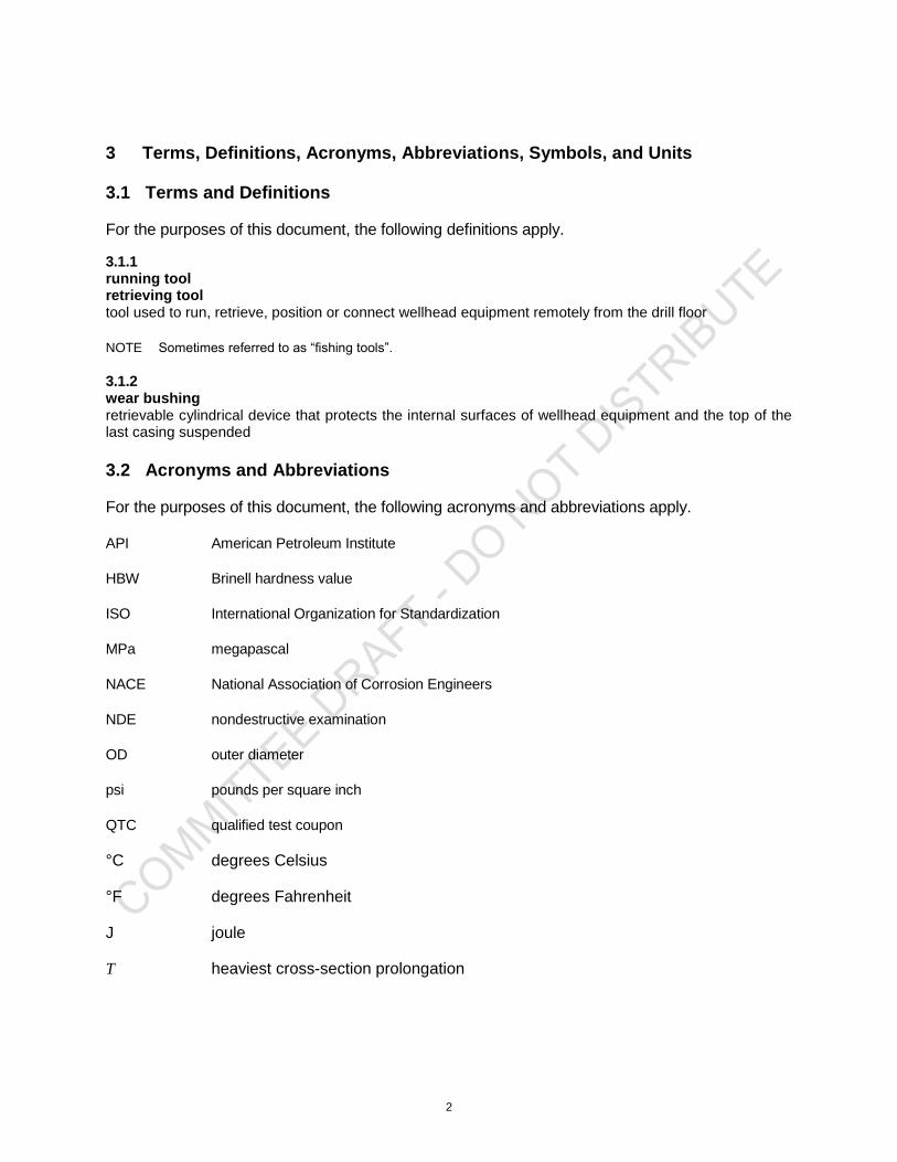
3 Terms, Definitions, Acronyms, Abbreviations, Symbols, and Units
3.1 Terms and Definitions
For the purposes of this document, the following definitions apply.
3.1.1 running tool retrieving tool tool used to run, retrieve, position or connect wellhead equipment remotely from the drill floor
NOTE Sometimes referred to as “fishing tools”.
3.1.2 wear bushing retrievable cylindrical device that protects the internal surfaces of wellhead equipment and the top of the last casing suspended
3.2 Acronyms and Abbreviations
For the purposes of this document, the following acronyms and abbreviations apply.
API American Petroleum Institute
HBW Brinell hardness value
ISO International Organization for Standardization
MPa megapascal
NACE National Association of Corrosion Engineers
NDE nondestructive examination
OD outer diameter
psi pounds per square inch
QTC qualified test coupon
°C degrees Celsius
°F degrees Fahrenheit
J joule
T heaviest cross-section prolongation

3
4 Design
4.1 General
The equipment manufactured in accordance with this technical report shall be designed to satisfy the manufacturer's documented performance characteristics and the service conditions specified in API 6A. The manufacturer shall specify methods for use in designs that are consistent with accepted engineering practices..
4.2 Loads
Design of running, retrieving, clean-out and testing tools shall include the following as a minimum:
suspended loads, including overpull;
bending loads;
pressure;
torsional loads, including the required make-up torque of shouldered connections;
radial loads;
environmental loads.
4.3 End Connections
Tool joints shall conform to the requirements of API 5DP. Rotary shouldered connections shall conform to the requirements of API 7-1. These elements shall be an integral part of the tool and shall not to be connected by welding. There shall be adequate space for elevator and rotary slips. The load capacity of the tool shall not be inferred by the choice of the end connection of the tool.
For attachments welded to tools, the following shall apply:
The following apply:
a) welding procedure/performance:
Welding procedures and performance qualifications shall be in accordance with ASME BPVC:2004, Section IX, Articles II and III with 2005 and 2006 addenda.
b) application:
Welding shall be performed in accordance with qualified procedures by qualified welding personnel. Non-pressure-containing weldments shall meet the manufacturer's design requirements.
c) quality control requirements:
Welding and completed welds shall meet the requirements of Table 1.
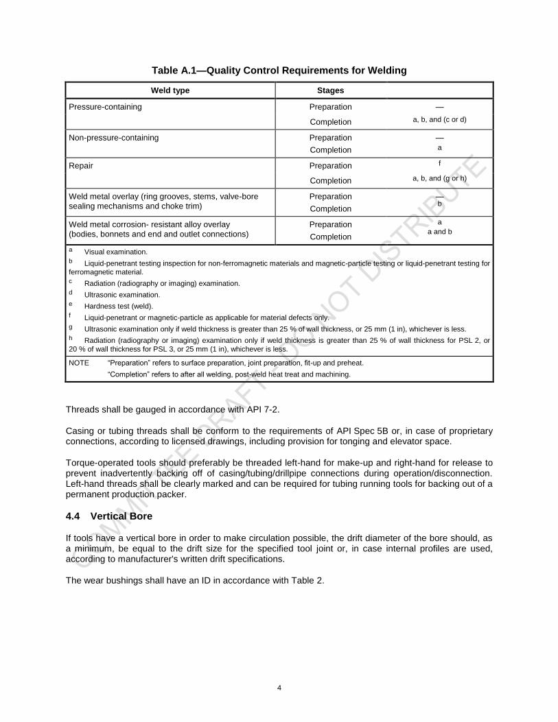
4
Table A.1—Quality Control Requirements for Welding
Weld type Stages
Pressure-containing Preparation —
Completion a, b, and (c or d)
Non-pressure-containing Preparation
Completion
— a
Repair Preparation f
Completion a, b, and (g or h)
Weld metal overlay (ring grooves, stems, valve-bore
sealing mechanisms and choke trim)
Preparation
Completion
— b
Weld metal corrosion- resistant alloy overlay
(bodies, bonnets and end and outlet connections)
Preparation
Completion
a a and b
a Visual examination.
b Liquid-penetrant testing inspection for non-ferromagnetic materials and magnetic-particle testing or liquid-penetrant testing for
ferromagnetic material.
c Radiation (radiography or imaging) examination.
d Ultrasonic examination.
e Hardness test (weld).
f Liquid-penetrant or magnetic-particle as applicable for material defects only.
g Ultrasonic examination only if weld thickness is greater than 25 % of wall thickness, or 25 mm (1 in), whichever is less.
h Radiation (radiography or imaging) examination only if weld thickness is greater than 25 % of wall thickness for PSL 2, or
20 % of wall thickness for PSL 3, or 25 mm (1 in), whichever is less.
NOTE “Preparation” refers to surface preparation, joint preparation, fit-up and preheat.
“Completion” refers to after all welding, post-weld heat treat and machining.
Threads shall be gauged in accordance with API 7-2.
Casing or tubing threads shall be conform to the requirements of API Spec 5B or, in case of proprietary connections, according to licensed drawings, including provision for tonging and elevator space.
Torque-operated tools should preferably be threaded left-hand for make-up and right-hand for release to prevent inadvertently backing off of casing/tubing/drillpipe connections during operation/disconnection. Left-hand threads shall be clearly marked and can be required for tubing running tools for backing out of a permanent production packer.
4.4 Vertical Bore
If tools have a vertical bore in order to make circulation possible, the drift diameter of the bore should, as a minimum, be equal to the drift size for the specified tool joint or, in case internal profiles are used, according to manufacturer's written drift specifications.
The wear bushings shall have an ID in accordance with Table 2.
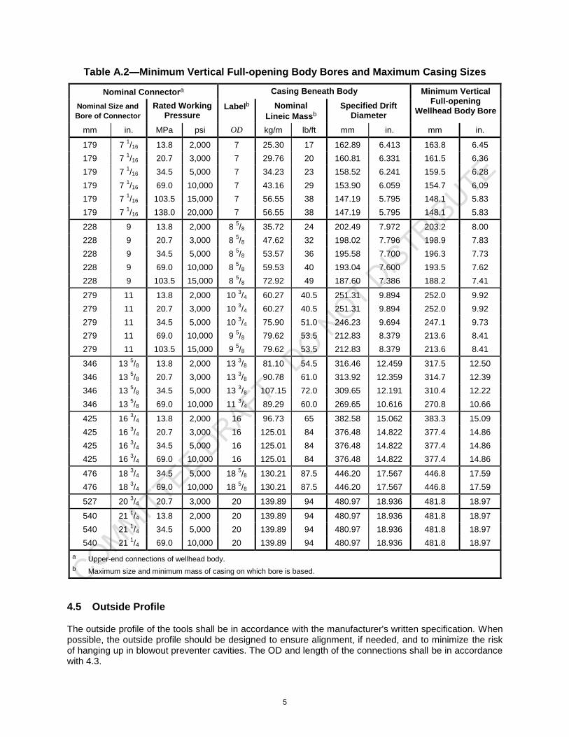
5
Table A.2—Minimum Vertical Full-opening Body Bores and Maximum Casing Sizes
Nominal Connectora Casing Beneath Body Minimum Vertical
Full-opening Wellhead Body Bore
Nominal Size and
Bore of Connector
Rated Working Pressure
Labelb Nominal
Lineic Massb
Specified Drift Diameter
mm in. MPa psi OD kg/m lb/ft mm in. mm in.
179 7 1/16 13.8 2,000 7 25.30 17 162.89 6.413 163.8 6.45
179 7 1/16 20.7 3,000 7 29.76 20 160.81 6.331 161.5 6.36
179 7 1/16 34.5 5,000 7 34.23 23 158.52 6.241 159.5 6.28
179 7 1/16 69.0 10,000 7 43.16 29 153.90 6.059 154.7 6.09
179 7 1/16 103.5 15,000 7 56.55 38 147.19 5.795 148.1 5.83
179 7 1/16 138.0 20,000 7 56.55 38 147.19 5.795 148.1 5.83
228 9 13.8 2,000 8 5/8 35.72 24 202.49 7.972 203.2 8.00
228 9 20.7 3,000 8 5/8 47.62 32 198.02 7.796 198.9 7.83
228 9 34.5 5,000 8 5/8 53.57 36 195.58 7.700 196.3 7.73
228 9 69.0 10,000 8 5/8 59.53 40 193.04 7.600 193.5 7.62
228 9 103.5 15,000 8 5/8 72.92 49 187.60 7.386 188.2 7.41
279 11 13.8 2,000 10 3/4 60.27 40.5 251.31 9.894 252.0 9.92
279 11 20.7 3,000 10 3/4 60.27 40.5 251.31 9.894 252.0 9.92
279 11 34.5 5,000 10 3/4 75.90 51.0 246.23 9.694 247.1 9.73
279 11 69.0 10,000 9 5/8 79.62 53.5 212.83 8.379 213.6 8.41
279 11 103.5 15,000 9 5/8 79.62 53.5 212.83 8.379 213.6 8.41
346 13 5/8 13.8 2,000 13
3/8 81.10 54.5 316.46 12.459 317.5 12.50
346 13 5/8 20.7 3,000 13
3/8 90.78 61.0 313.92 12.359 314.7 12.39
346 13 5/8 34.5 5,000 13
3/8 107.15 72.0 309.65 12.191 310.4 12.22
346 13 5/8 69.0 10,000 11
3/4 89.29 60.0 269.65 10.616 270.8 10.66
425 16 3/4 13.8 2,000 16 96.73 65 382.58 15.062 383.3 15.09
425 16 3/4 20.7 3,000 16 125.01 84 376.48 14.822 377.4 14.86
425 16 3/4 34.5 5,000 16 125.01 84 376.48 14.822 377.4 14.86
425 16 3/4 69.0 10,000 16 125.01 84 376.48 14.822 377.4 14.86
476 18 3/4 34.5 5,000 18
5/8 130.21 87.5 446.20 17.567 446.8 17.59
476 18 3/4 69.0 10,000 18
5/8 130.21 87.5 446.20 17.567 446.8 17.59
527 20 3/4 20.7 3,000 20 139.89 94 480.97 18.936 481.8 18.97
540 21 1/4 13.8 2,000 20 139.89 94 480.97 18.936 481.8 18.97
540 21 1/4 34.5 5,000 20 139.89 94 480.97 18.936 481.8 18.97
540 21 1/4 69.0 10,000 20 139.89 94 480.97 18.936 481.8 18.97
a Upper-end connections of wellhead body.
b Maximum size and minimum mass of casing on which bore is based.
4.5 Outside Profile
The outside profile of the tools shall be in accordance with the manufacturer's written specification. When possible, the outside profile should be designed to ensure alignment, if needed, and to minimize the risk of hanging up in blowout preventer cavities. The OD and length of the connections shall be in accordance with 4.3.

6
4.6 Pressure Rating
The pressure rating of the tool shall, if applicable, be in accordance with the manufacturer's written specification.
5 Materials
5.1 General
All tools and parts thereof shall require a written material specification that shall define the following, along with accept/reject criteria:
mechanical property requirements;
material qualification;
heat-treatment procedure, including cycle time and temperatures with tolerances;
material composition with tolerances;
NDE requirements;
allowable melting practice(s);
hot-working practice(s);
cooling media when heat treating.
Running tools shall be fabricated from materials that meet the applicable property requirements as specified by the manufacturer.
5.2 Additional Requirements
5.2.1 General
Sections 5.2 to 5.4 shall apply only to major load-bearing tools, such as casing and tubing running tools, cup-type tester and seal assembly setting tools required to transmit torque that is higher than 50 % of the make-up torque of the tool.
5.2.2 Heat Treatment
Heat treatment shall be performed in accordance with the manufacturer's written specification. This specification shall contain all necessary information to perform the heat treatment of each selected material or part in order to obtain the required mechanical properties.
5.2.3 Chemical Composition
Materials shall conform to the manufacturer's written specification.
The manufacturer shall specify the nominal chemical composition, including the composition tolerances, of the material.
The material composition shall be determined on a heat basis (or a remelt ingot basis for remelt grade materials) in accordance with an internationally recognized standard specified by the manufacturer.
7
5.2.4 Material Qualification
5.2.4.1 Qualified Test Coupon
The qualified test coupon (QTC) for a running tool shall be a full section prolongation.
NOTE The prolongation may be heat-treated either attached or separated from the running tools it represents.
The prolongation shall be sufficiently long to ensure that mechanical test specimens (see 5.2.4.3) can be taken at least
1/4 T (where T is the heaviest cross-section of the prolongation) from the nearest heat-
treated surface.
If a running tool is preheat-machined to different diameters, the prolongation shall be taken from the end having the largest diameter.
5.2.4.2 Qualification Lot
The QTC shall represent identical running tools that are from the same heat and heat-treated together in the same furnace at the same time (heat per heat-treat-lot testing). An attached prolongation, if used, shall remain attached to a production running tool throughout heat treatment, except for re-tempering or re-ageing cycles when required.
5.2.4.3 Mechanical Testing
A minimum of one tensile test and three Charpy V-notch tests shall be performed on each QTC. Full-size specimens shall be used. Testing shall be performed in accordance with ISO 148 (all parts) or ASTM A370. Impact test temperature shall be no higher than the lowest anticipated service temperature.
The following apply.
a) Test specimens shall be removed from the QTC such that the tensile specimen gauge length and the Charpy V-notch root are at least
1/4 T from the “as-heat-treated” ends of the QTC (T is the heaviest
cross-section of the prolongation). The longitudinal axis of the tensile and Charpy specimens shall be taken within the centre
1/4 T envelope for solid QTCs or within 3 mm (
1/8 in) of the mid-wall for hollow
QTCs.
b) Hardness testing shall be carried out as specified by the manufacturer.
5.3 Mechanical Property Requirements
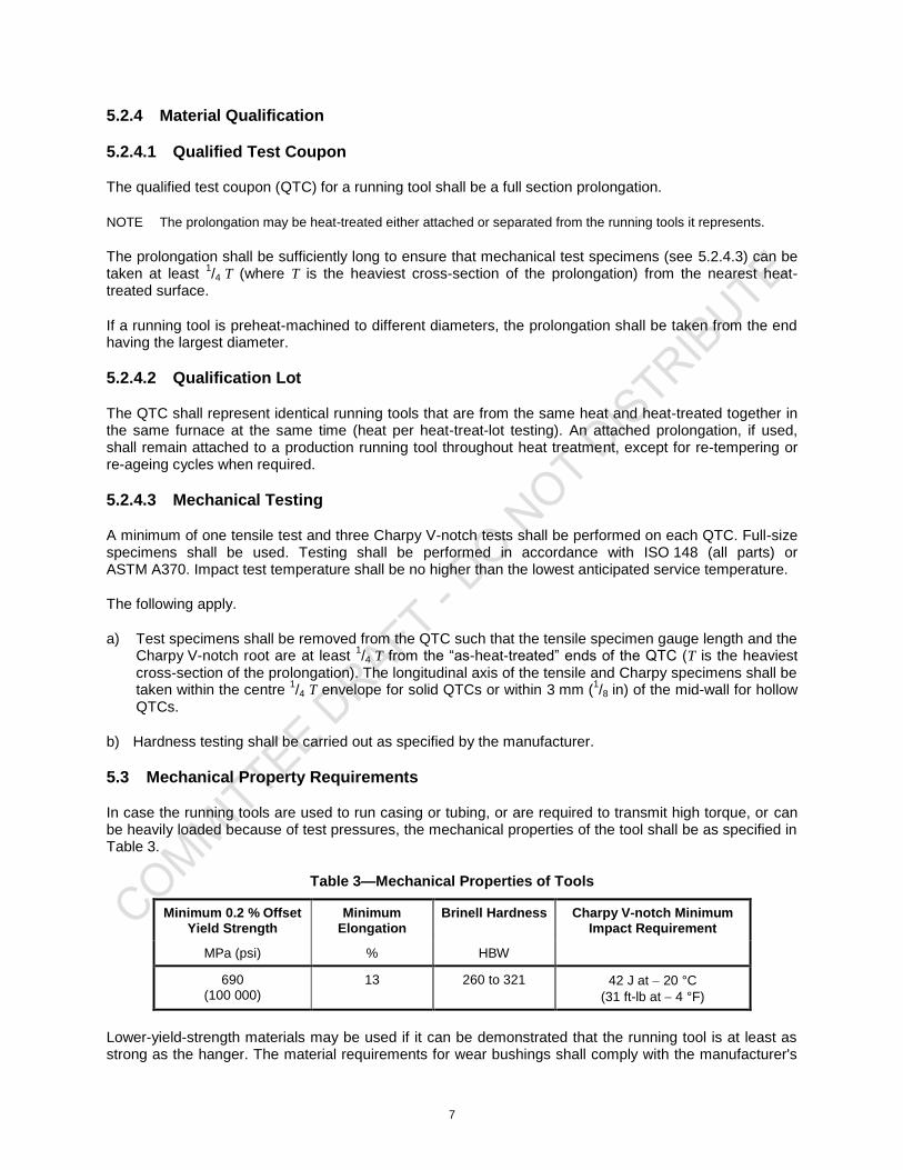
In case the running tools are used to run casing or tubing, or are required to transmit high torque, or can be heavily loaded because of test pressures, the mechanical properties of the tool shall be as specified in Table 3.
Table 3—Mechanical Properties of Tools
Minimum 0.2 % Offset Yield Strength
Minimum Elongation
Brinell Hardness Charpy V-notch Minimum Impact Requirement
MPa (psi) % HBW
690 (100 000)
13 260 to 321 42 J at 20 °C
(31 ft-lb at 4 °F)
Lower-yield-strength materials may be used if it can be demonstrated that the running tool is at least as strong as the hanger. The material requirements for wear bushings shall comply with the manufacturer's
8
written specification; however, the hardness should be between 241 HBW and 321 HBW. Impact testing is not required for wear bushing material. The ratio of yield strength to tensile strength shall not exceed 0.90.
5.4 Coatings
The rotary connections of the tools shall be coated with an anti-galling agent.
6 Testing
All tools shall, as far as reasonably possible, be functionally tested and dimensionally inspected or gauged to confirm their correct operation prior to shipment from the manufacturer's facility. Tools with hydraulic operating systems shall have the hydraulic system tested in accordance with the manufacturer's written specification. This hydrostatic test shall consist of three steps:
a primary pressure-holding period;
a reduction of the pressure to zero (atmospheric pressure);
a secondary pressure-holding period.
Each holding period shall not be less than 15 min; the timing shall not start until the external surfaces of the body members have been thoroughly dried, the test pressure has been reached and the equipment and the pressure-monitoring gauge have been isolated from the pressure source.
7 Marking
All tools shal be marked “6RT” and also as indicated in API 5DP below the tool joint tong space, as a minimum. Wear bushings shall be marked “6RT” followed by the drift internal diameter, expressed in millimetres and inches. A unique serial number shall be die-fixed to each tool assembly, preferably in a milled recess.
8 Quality Control Record Requirements
8.1 General
8.1.1 Purpose
The quality control records required by this International Standard are necessary to substantiate that all materials and products made to meet this International Standard do conform to the specified requirements.
8.1.2 ISO 15156 (all parts) (NACE MR0175; see Clause 2) Records Requirements
Records required to substantiate conformance of equipment manufactured with sour service material classes (see ISO 15156 (all parts) (NACE MR0175; see Clause 2) requirements shall be in addition to those described in 8.1.4, unless the records required by this technical report also satisfy the ISO 15156 (all parts) (NACE MR0175; see Clause 2) requirements.
9
8.1.3 Records Control
The following apply.
c) Quality control records required by this International Standard shall be legible, identifiable, retrievable and protected from damage, deterioration or loss.
d) Quality control records required by this International Standard shall be retained by the manufacturer for a minimum of five years following the date of manufacture as marked on the equipment associated with the records.
e) All quality control records required by this International Standard shall be signed and dated.
8.1.4 Manufacturer Records
The following records shall be maintained by the manufacturer:
― material test records:
chemical analysis,
tensile test,
impact test (if required),
hardness test;
― welding process records:
weld procedure specification,
weld procedure qualification record,
welder qualification record;
― NDE personnel qualification records;
― hardness test (if applicable);
― NDE records:
surface NDE records,
weld volumetric NDE records,
repair weld NDE records;
― heat-treatment certificate of compliance
10
9 Storing and Shipping
Thread Protection 9.1
Threads shall be protected by a proper storage compound and a metal pressed thread protector or equivalent.
Draining After Testing 9.2
All equipment shall be drained and lubricated after testing and prior to storage or shipment.
Rust Prevention 9.3
Prior to shipment, parts and equipment shall have exposed metallic surfaces protected with a rust preventative that does not become fluid and run at a temperature of less than 50 °C (125 °F).
Sealing-surface Protection 9.4
Exposed sealing surfaces shall be protected from mechanical damage for shipping.
Assembly and Maintenance Instructions 9.5
The manufacturer shall furnish to the purchaser suitable drawings and instructions concerning field assembly and maintenance. This includes, if relevant, an operating manual for the equipment.
Ring Gaskets 9.6
Loose ring gaskets shall be boxed or wrapped during shipping and storage.
Age control of Non-metallic Materials 9.7
Age-control procedures and the protection of non-metallic seals shall be documented by the manufacturer.
The manufacturer shall define the provisions and requirements.

11
Bibliography