design and installation of hydronic snow and ice … · ©2017 plastics pipe institute design and...
TRANSCRIPT

©2017 Plastics Pipe Institute
Design and Installation of Hydronic Snow and Ice Melting (SIM) Systems to Optimize Performance and Efficiency

©2017 Plastics Pipe Institute
Introduction
Lance MacNevin, P.Eng.- Originally from Charlottetown, PEI- Graduated UNB 1992- Working in the hydronics industry since 1993- Director of Engineering, Building & Construction Division- Tel (469) 499-1057 [email protected]

©2017 Plastics Pipe Institute
Introduction to the Plastics Pipe Institute
PPI is a non-profit trade association representing the plastic pipe industry- PPI’s five divisions focus on solutions for multiple applications:
- Building & Construction Division (BCD)- Corrugated Plastic Pipe Association (CPPA)- Energy Piping Systems Division (EPSD)- Municipal & Industrial Division (MID)- Power & Communications Division (PCD)
PCD: HDPE Conduit for fiber optic EPSD: Gas distribution piping MID: HDPE water mains

©2017 Plastics Pipe Institute
Introduction to the Plastics Pipe Institute
PPI’s Building & Construction Division (BCD)- BCD is focused on plastic pressure pipe and tubing systems used within buildings
and on building premises for applications such as plumbing, water service, fire protection, hydronic heating and cooling, snow and ice melting and ground source geothermal piping systems: PEX, CPVC, PE-RT, PP-R
- BCD is involved with many industry groups:

©2017 Plastics Pipe Institute
What Is A Hydronic SIM System?
- Snow and Ice Melting (SIM) systems are hydronic systems designed to remove snow and ice by circulating a heat transfer fluid through tubing installed in an outdoor surface
- SIM systems are used across North America in all climates
- The piping material for SIM systems is typically:- PEX: Crosslinked Polyethylene (see CSA B137.5)- PE-RT: Polyethylene of Raised Temperature resistance (see CSA B137.18)- PP-R: Random Copolymerized Polypropylene (see CSA B137.11)- Type K soft copper tubing
- Learn more about these materials at http://plasticpipe.org/building-construction/

©2017 Plastics Pipe Institute
Relevance of Hydronic SIM Systems
1. The safety, convenience and savings provided by a SIM system are more beneficial than ever, as changing weather patterns increase snowfall in many regions
2. Clearing slippery outdoor surfaces over a long winter is a high maintenance cost and involves the expense of harsh chemicals which can damage surfaces
3. Aging populations need access to services, yet may have limited mobility4. Snow and ice melting systems can reduce liability while improving access5. Operating costs for a hydronic SIM system are often much less than mechanical
snow removal, saving facility owners money while reducing risks

©2017 Plastics Pipe Institute
Relevance of Hydronic SIM Systems
Annual snowfall data for Toronto 1995-2016 shows blips, not trends- Winters are unpredictable but reliable- Data at https://toronto.weatherstats.ca/metrics/snow.html

©2017 Plastics Pipe Institute
Course Outline
This course will:
1. Indicate the typical benefits of SIM systems
2. Describe the three most common installation techniques
3. List a selection of typical applications
4. Introduce the five main design steps
5. Discuss the most common control strategies
6. Comment on operating costs

©2017 Plastics Pipe Institute
1. Benefits of Snow and Ice Melting Systems
This section will explain at least six benefits of SIM systems
- Better safety- Reduced liability- Healthier convenience- Lowered maintenance costs- Minimized environmental impact- Long-term reliability

©2017 Plastics Pipe Institute
Benefits of Snow and Ice Melting Systems
Better Safety- Snow and ice melting systems eliminate build-up of snow and ice, keeping surfaces
clear during snowfall events and evaporating water to prevent freezing- Systems provide better safety for walkers and drivers than mechanical snow removal
Courtesy NIBCO

©2017 Plastics Pipe Institute
Benefits of Snow and Ice Melting Systems
Reduced Liability- Keeping residences and businesses free of snow and ice improves access and safety,
while eliminating a source of liability risk in winter- Snowbanks and trip hazards are practically eliminated- Liability insurance premiums might even be reduced, reducing ownership costs
Bus station loading area.
Unfortunately, no tubing in the curb.

©2017 Plastics Pipe Institute
Benefits of Snow and Ice Melting Systems
Healthier Convenience- For the ultimate in snow removal convenience,
SIM systems clear outdoor surfaces, leaving them dry - No snow banks are left behind- For residential customers, this eliminates potential
health risks of aching backs and heart attacks
Courtesy Ridgeway Home Services

©2017 Plastics Pipe Institute
Benefits of Snow and Ice Melting Systems
Lowered Maintenance Costs- Traditional snow removal is very expensive and unpredictable- Facility owners can pay $10,000s per year for labor, equipment, supplies- Hydronic SIM systems are usually less expensive to operate than mechanical removal- Indoor maintenance costs are reduced by avoiding sand and salt getting tracked inside

©2017 Plastics Pipe Institute
Benefits of Snow and Ice Melting Systems
Minimized Environmental Impact- Hydronic SIM systems are powered by heat sources such as high-efficiency boilers,
electricity, thermal solar, geothermal heat pumps or waste heat (commercial, industrial)- They extend lives of surfaces by eliminating scraping, salting and sanding operations- Run-off of deicing chemicals (e.g. salt) onto lawns and drains is eliminated- Less fuel is used to power boilers than to power trucks (lower CO2 emissions)- These factors can reduce environmental impacts

©2017 Plastics Pipe Institute
Benefits of Snow and Ice Melting Systems
Long-term Reliability- Plastic tubing does not corrode on the inside or outside- Hydronic boilers, circulators and piping components are highly reliable- With proper design and installation, hydronic SIM systems provide decades of
reliable operation with virtually no maintenance to piping systems- The piping material for SIM systems is typically:
- PEX: Crosslinked Polyethylene (see CSA B137.5)- PE-RT: Polyethylene of Raised Temperature resistance (see CSA B137.18)- PP-R: Random Copolymerized Polypropylene (see CSA B137.11)

©2017 Plastics Pipe Institute
Benefits of Snow and Ice Melting Systems
Summary: Typical benefits include
- Better safety- Reduced liability- Healthier convenience- Lowered maintenance costs- Minimized environmental impact- Long-term reliability

©2017 Plastics Pipe Institute
2. SIM Installation Techniques
This section describes three common installation types for outdoor surfaces
1. Poured concrete2. Interlocking pavers3. Asphalt
Hydronic snow and ice melting systems can be successfully installed in practically all types* of external surfaces *Permeable concrete is the most difficult surface

©2017 Plastics Pipe Institute
SIM Installation Techniques
Tubing embedded within poured concrete
- In poured concrete, the tubing is simplyembedded within the concrete
- Very popular for stained concrete - Recommended to place the tubing 2 to 3 in.
(5 - 8 cm) below the surface for faster response time (this is not always practical)
- Tubing is often stapled directly onto the insulation board or tied to rebar or wire mesh within the poured structural concrete
- Some insulation board has the integrated “knobs” for holding the tubing- This is a simple and affordable technique for installing SIM piping

©2017 Plastics Pipe Institute
SIM Installation Techniques
Tubing embedded within poured concrete
Poured concrete with tubing embedded 2 to 3 inch from top surface
Courtesy Uponor

©2017 Plastics Pipe Institute
SIM Installation Techniques
Tubing embedded within poured concrete
Poured concrete with tubing embedded 2 to 3 inch from top surface
Courtesy Ridgeway Home Services

©2017 Plastics Pipe Institute
SIM Installation Techniques
Tubing installed under interlocking pavers
- Plastic tubing is installed above insulation using plastic rails, staples or screw clips
- Tubing is encased within 1 1/2 in. (4 cm) of sand bed, compacted to 1 1/8 in. (3 cm)
- Pavers are placed above sand bed and installed normally
- Technical specifications and drawings of SIMsystems with pavers can be found at www.icpi.org
Media- Compacted sand bed is recommended- Stone dust loses strength when wet, and can heave when frozen

©2017 Plastics Pipe Institute
SIM Installation Techniques
Tubing installed under interlocking pavers
Pavers installed over sand bed with embedded heating tubing
Courtesy Ridgeway Home Services

©2017 Plastics Pipe Institute
SIM Installation Techniques
Tubing installed under asphalt
- Plastic tubing is installed above insulation using plastic rails, staples or screw clips
- Tubing is encased within 3 in. (7.5 cm) of stone dust or sand media, compacted
- Asphalt is placed above the media and compacted normally
- Cold water is flushed through pipes during placement of asphalt and until it cools
- Water flow is regulated to be less than 150°F (65°C)at the manifold outlet to keep the tubing “cool”
Media: Compacted stone dust works best. No pea stone or crushed gravel.

©2017 Plastics Pipe Institute
SIM Installation Techniques
Tubing installed under asphalt
Tubing embedded within sandor stone dust below asphalt

©2017 Plastics Pipe Institute
SIM Installation Techniques
Importance of Insulation- A significant amount of heat can be conducted to the frozen earth below the SIM
surface if appropriate insulation is not installed- Without insulation, downward losses can exceed 50% of all the energy supplied
to the area (so double the size of heat source and circulators!)= Tubing filled with warm glycol
Bottom Insulation

©2017 Plastics Pipe Institute
SIM Installation Techniques
Importance of Insulation- Insulation may be extruded polystyrene (XPS), polyurethane (PU), or expanding
foam that is sprayed onto existing concrete or the earth to follow contours - CSA B214-16 requires at least R-5 insulation below SIM areas, but many designers
specify R-10, since insulation also improves response time- Typical insulation thickness is 1 in., 1 ½ in. or 2 in. (25 mm, 38 mm, 50 mm)
- Be sure the insulation is rated for outdoor use and meets the expected compressive loading from vehicles, or settling can occur

©2017 Plastics Pipe Institute
SIM Installation Techniques
Importance of Insulation
Courtesy Viega LLC

©2017 Plastics Pipe Institute
SIM Installation Techniques
Summary: This section described three installation types for outdoor surfaces
1. Poured concrete2. Interlocking concrete pavers3. Asphalt
Images Courtesy REHAU

©2017 Plastics Pipe Institute
3. Typical applications of SIM systems
This section gives examples of application types
1. Sidewalks2. Steps3. Driveways4. Ramps5. Roads6. Parking garages7. Hangers8. Pool decks9. Train stations10. Aviation11. Melting “hot pads”

©2017 Plastics Pipe Institute
Typical applications of SIM systems
Sidewalks- Private home

©2017 Plastics Pipe Institute
Typical applications of SIM systems
Sidewalks- Commercial building
Courtesy Zurn

©2017 Plastics Pipe Institute
Typical applications of SIM systems
Sidewalks- Municipal building - University (handicapped parking)
Courtesy Klimatrol

©2017 Plastics Pipe Institute
Typical applications of SIM systems
Sidewalks- Hotel

©2017 Plastics Pipe Institute
Typical applications of SIM systems
Steps- Public and commercial spaces
Courtesy REHAU Courtesy NIBCO

©2017 Plastics Pipe Institute
Typical applications of SIM systems
Steps- Residential installations
Courtesy KlimatrolCourtesy Ridgeway Home Services

©2017 Plastics Pipe Institute
Typical applications of SIM systems
Driveways- Under stained concrete or pavers
Courtesy Klimatrol Courtesy Ridgeway Home Services

©2017 Plastics Pipe Institute
Typical applications of SIM systems
Driveways- Under stained concrete or pavers
Courtesy Klimatrol

©2017 Plastics Pipe Institute
Typical applications of SIM systems
Driveways- Under stained concrete or pavers
Courtesy Thornton Plumbing & Heating
©2017 Plastics Pipe Institute
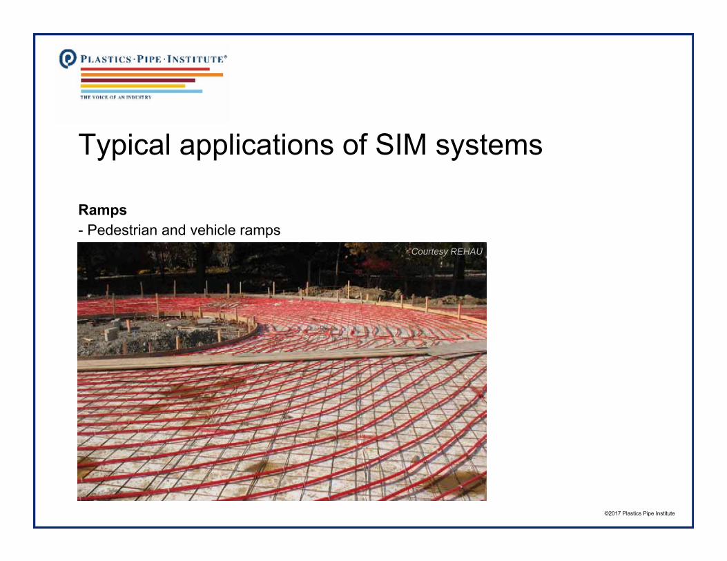
Typical applications of SIM systems
Ramps- Pedestrian and vehicle ramps
Courtesy REHAU

©2017 Plastics Pipe Institute
Typical applications of SIM systems
Ramps- Pedestrian and vehicle ramps
Courtesy REHAU

©2017 Plastics Pipe Institute
Typical applications of SIM systems
Roadways- SIM systems add safety with steep inclines
Courtesy REHAU

©2017 Plastics Pipe Institute
Typical applications of SIM systems
Parking garages- SIM in the inclined ramps and in exposed levels of ramps
Courtesy REHAU

©2017 Plastics Pipe Institute
Typical applications of SIM systems
Hanger doors and aprons- SIM prevents sliding doors from freezing
Courtesy VIEGA LLC

©2017 Plastics Pipe Institute
Typical applications of SIM systems
Pool decks- Facilitates winter access- Tubing can also be used
to extract heat from surfacein summer to cool the deck
- Same heat can be “pumped”back into the pool

©2017 Plastics Pipe Institute
Typical applications of SIM systems
Train stations- Add safety and convenience to outside train stations and platforms
Courtesy KlimatrolCourtesy REHAU

©2017 Plastics Pipe Institute
Typical applications of SIM systems
Aviation- Train tracks at airports

©2017 Plastics Pipe Institute
Typical applications of SIM systems
Aviation- Medivac landing pads

©2017 Plastics Pipe Institute
Typical applications of SIM systems
Aviation- Ramps, taxiways, runways
YYZ Pearson does not have a SIM system!
Fleet of scrapers, blowers, melters, and fuel trucks

©2017 Plastics Pipe Institute
Typical applications of SIM systems
Aviation- Alternative…

©2017 Plastics Pipe Institute
Typical applications of SIM systems
Melting Hot Pads- What to do with all that snow?- Build a hydronic SIM system
surrounding drains- Push snow onto the “hot pad”
or “melting pad” and melt away- Just like a Zamboni melting pit!
- Critical in cities and commercial facilities

©2017 Plastics Pipe Institute
Typical applications of SIM systems
Summary: This section listed examples of applications
1. Sidewalks2. Steps3. Driveways4. Ramps5. Roads6. Parking garages7. Hangers8. Pool decks9. Train stations10. Aviation11. Melting “hot pads”

©2017 Plastics Pipe Institute
4. SIM Design Steps
Melting snow is basically a three-step process:1. Warm the snow or ice to the melting temperature by applying 0.51 Btu/lb2. Melt the snow into cold water; the latent heat of fusion for melting is 144 Btu/lb3. Evapourate the water (or let it drain off)

©2017 Plastics Pipe Institute
SIM Design Steps
SIM heat loads are based on several factors:
- Slab temperature at start of snowfall- Air temperature when snowing/melting- Rate of snow fall- Snow density- Wind velocity- Apparent sky temperature- Humidity level of the atmosphere
These issues must be taken into account when predicting SIM loads
Courtesy Thornton Plumbing & Heating

©2017 Plastics Pipe Institute
SIM Design Steps
This section will introduce the five main design steps1. Select the appropriate performance level for the customer2. Determine the required heat output/heat flux3. Select and size heat source to meet the peak load4. Design the piping distribution system in terms of size, spacing, circuit lengths5. Size hydronic equipment such as circulator pumps, expansion tanks, etc.
Courtesy Arndt & Son

©2017 Plastics Pipe Institute
SIM Design Steps
1. Select the Appropriate Performance Level
- ASHRAE HVAC Applications “Ch. 51 Snow Melting and Freeze Protection”includes tables showing Frequencies of snow-melting surface heat fluxes at steady state conditions for major US cities
- For cities not found in that table, a series of 14 calculations can be used to estimate the loads based on historical weather data for that location
- The designer and customer agree to the most appropriate Snow-Free Area Ratio and Frequency Distribution
- Then, the specific heat loads can be selected from the published data, weather research or case studies

©2017 Plastics Pipe Institute
SIM Design Steps
1. Select the Appropriate Performance Level
- ASHRAE HVAC Applications “Ch. 51 Snow Melting and Freeze Protection” provides relevant information for US cities for these calculations (with some assumptions)
- Designers can pick a similar Canadian city and use the Table- Historical Weather Data found at http://climate.weather.gc.ca/index_e.html
Courtesy Thornton Plumbing & Heating

©2017 Plastics Pipe Institute
SIM Design Steps
1. Select the Appropriate Performance Level
- ASHRAE HVAC Applications “Ch. 51 Snow Melting and Freeze Protection”- See excerpt below for Madison, WI:
- Frequency Distribution makes sense, but what about Snow-Free Area Ratio?

©2017 Plastics Pipe Institute
SIM Design Steps
1. Select the Appropriate Performance Level
Snow-Free Area Ratios:
- Ar = 1.0 Snow-Free Area of 100% No accumulation during snowfall
- Ar = 0.5 Snow-Free Area of 50%Some accumulation during snowfall
- Ar = 0.0 Snow-Free Area of 0%Surface may be covered with snow during heavy snowfall, melting snowfrom the bottom of the layer Ex: Ar = 0.5 is 50% snow-free during snow fall
Snow will be completely melted, evaporated and dried before system turns off
Courtesy Thornton Plumbing & Heating

©2017 Plastics Pipe Institute
SIM Design Steps
1. Select the Appropriate Performance Level- Suggested Performance Levels:
Note:These are friendly suggestions to help manage expectations.
Each customer should decide and confirm what is expected for their project.

©2017 Plastics Pipe Institute
SIM Design Steps
1. Select the Appropriate Performance Level- Sample heat flux values (for a climate similar to Boston, MA):

©2017 Plastics Pipe Institute
SIM Design Steps
1. Select the Appropriate Performance Level
Example: Parking Ramp in Hamilton, Ontario
- Owner requests system to be 100% snow-free during 95% of snowfall events
- Owner agrees that even in more severe weather, this system will be adequate
- This means Ar = 1.0 @ 95% frequency distribution- Melting area: 1,000 ft2 (92 m2)

©2017 Plastics Pipe Institute
SIM Design Steps
2. Determine Required Heat Output: Melting Operation
- Designer determines that for this project and location, with Ar = 1.0 @ 95% frequency distribution, system must supply 150 Btuh/ft2 output (based on weather research)
- Must also expect 20% downward loss: 150 Btuh/ft2 x 1.2 = 180 Btuh/ft2
- Required output is 180 Btuh/ft2
Insulation

©2017 Plastics Pipe Institute
SIM Design Steps
3. Select and Size Heat Source
- Total load: 1,000 ft2 x 180 Btuh/ft2 = 180,000 Btuh required output- This is the total heat load for sizing the source, circulator, and piping network
Heat source options:- Dedicated boiler sized for this load- Shared boiler sized for the SIM load plus heating loads
or swimming pool or radiant heating - Be sure the SIM portion contains glycol antifreeze
- Approved combi-heater unit- Geothermal water-to-water heat pump- Waste heat from industrial processes- Rejected heat from commercial cooling system
This system will use a dedicated boiler

©2017 Plastics Pipe Institute
SIM Design Steps
4. Design the Piping Distribution System
The designer selects:a. Tube size (3/4 NTS tubing is typical; 1/2 in. and 5/8 in. tubing is sometimes used)b. Tube spacing (6 to 9 inch tube spacing is typical, based on width of area)c. Tube circuit lengths (100 ft. to 300 ft. circuit length is typical, but this is
based on load, tubing size, heated area and the selected circulator)
Poured concrete with tubing embedded 2 in. to 3 in. from top surface is ideal for faster response timeInsulation

©2017 Plastics Pipe Institute
SIM Design Steps
4. Design the Piping Distribution System
The designer selects:a. ¾ Tube size (¾ NTS tubing is typical; 1/2 and 5/8 tubing sometimes used)b. 8 in. Tube spacing (6 to 9 inch tube spacing is typical, based on width of area)c. 250 ft. Circuit lengths (100 ft. to 300 ft. circuit length is typical, based on heat load,
tubing size, heated area and the selected circulator)
Poured concrete with tubing embedded 2 in. to 3 in. from top surface is ideal for faster response time

©2017 Plastics Pipe Institute
SIM Design Steps
4. Design the Piping Distribution System
- Reference, CSA B214-16 (www.shopcsa.ca)

©2017 Plastics Pipe Institute
SIM Design Steps
4. Design the Piping Distribution System
- Chosen design uses 3/4 in. tubing @ 8 in. spacing - This spacing requires 1.5 ft. tubing per ft2, based on simple math 12”/8” = 1.5
- 1,000 ft2 x 1.5 ft. tubing per ft2 = 1,500 ft. of tubing total requirement
- Divide the 1,500 ft. total length into 6 equal circuits:
- 1,500 ft. ÷ 6 Circuits = 250 ft/circuit (each circuit covers 167 ft2)
- Heat load per circuit: 180,000 Btuh ÷ 6 = 30,000 Btuh per circuit

©2017 Plastics Pipe Institute
SIM Design Steps
4. Design the Piping Distribution System
- Tubing layout will have 6 equal circuits, each delivering up to 30,000 Btuh, through a nearby manifold
- Using 50% Glycol and a 25ºF ΔT:
- 180,000 Btuh = 16.3 GPM flow rate (2.7 GPM/circuit)11,030 Btu/GPM
- This info can be used to determine head loss through the piping networkusing the PPI Plastic Pressure Pipe Design Calculator
Courtesy REHAU

©2017 Plastics Pipe Institute
SIM Design Steps
4. Design the Piping Distribution System
- Evaluate head loss with 2.7 GPM in ¾ PEX or PE-RT:- PPI Plastic Pressure Pipe Design Calculator www.plasticpipecalculator.com- Head loss is 17.0 feet (velocity is 2.4 ft/s) in the distribution pipes

©2017 Plastics Pipe Institute
SIM Design Steps
5. Perform Hydronic Calculations
- Size heat source piping, circulator, valves, etc. around this flow requirement- Size expansion tank considering large range of temperatures- Size the piping to the manifold to minimize head loss (probably 1 ¼” PEX)- Calculate head loss through each component which is in series to determine the
total head loss value for selecting circulator
Courtesy Arndt & Son

©2017 Plastics Pipe Institute
SIM Design Steps
Summary: This Learning Objective introduced the five main design steps
1. Select the appropriate performance requirement2. Determine the required heat output3. Select and size heat source to meet the load4. Design the distribution system in terms of size, spacing and layout5. Perform hydronic calculations for sizing equipment such as circulator pumps,
expansion tanks, etc.

©2017 Plastics Pipe Institute
5. Control Strategies
This section discusses three control strategies
a. On/Off – System turns on with moisture + cold, turns off when dry- The most economical in terms of annual operating costs- May be fully automatic, or use outdoor moisture sensor (options)
b. Idle/Melt – Idles when dry, heats up with moisture + cold- Reduces response time to start melting- Consumes much energy to stay warm in between events
c. Always On – Constantly keeps outdoor surface warm, always ready to melt- Electronic control will monitor supply/return fluid temperatures to modulate the
fluid temperature and the heat output, as needed

©2017 Plastics Pipe Institute
Control Strategies
a. On/Off – System turns on with moisture + cold, turns off when dry- Cold start each time there is snow or ice- A “semi-automatic” control provides electronic slab temperature control with fluid
temperature modulation, starting with human initiation
Pros- “Semi-automatic” control lowers capital cost, good for many residential systems- A “fully automatic” control with moisture and temperature detection operates
autonomously, provides lots of tuning possibilities
Cons- With “semi-automatic”, a human needs to turn it on and set the timer- Can underperform if not operated correctly, can waste energy if overused

©2017 Plastics Pipe Institute
Control Strategies
b. Idle/Melt – Idles when dry, heats up with moisture + cold- Reduces response time to start melting operation- Typical idle temperature is 28°F (-2°C) - adjustable- Typical melting temperature is 38°F (4°C) – adjustable- Can program “cold weather cut-off” to prevent heating when it’s too cold to snow
Pros- Reduces response time to start melting- Avoids heat/cool cycles for delicate outdoor surfaces- Automatic controls can improve safety and save energyCons- Idling consumes much energy, to stay warm in between events- May increase annual energy consumption by 4 to 8 times due to Idling

©2017 Plastics Pipe Institute
Control Strategies
c. Always On – Constantly keeps outdoor surface warm, always ready to melt- Electronic control will monitor outdoor surface temperature and modulate the fluid
temperature and the heat output, as needed, to keep surface warm- May be suitable when the SIM load is a fraction of the total building heat load
Ex: Entrance to a hospital, sidewalk in a university campus
Pros- Always ready, ultimate safety- Avoids complexity of controls- Great way to reject process heat or excess building heat- Warm sidewalks feel good in winter!Cons- Always using energy

©2017 Plastics Pipe Institute
Control Strategies
Moisture and temperature sensors are installed in ramps, sidewalks, driveways
Sensor socket before concrete Sensor within a ramp Sensor close-up

©2017 Plastics Pipe Institute
Control Strategies
Moisture and temperature sensor placement recommendations:- Install in the first area to be hit with blowing or falling snow- The last place to be warmed by the sun- Last place to be dried due to drainage- Align sensor surface parallel to the slope of the surface- Brush off sand and dirt regularly
Avoid placing sensors:- Under parked cars- In vehicle tire tracks- In protected areas, like beside bushes or under the roof
Sensor height being aligned with future top surface

©2017 Plastics Pipe Institute
Control Strategies
This section discusses three control strategies
- We didn’t even mention smart web-based controls, or “apps”- There are many specific options available from experienced firms

©2017 Plastics Pipe Institute
6. Comments on Operating Costs
This section discusses methods to estimate SIM operating costs
The math is simple if you can predict or estimate:- Location- Melting area (of the surface)- Annual hours of operation (melting)- Number of events (for pick-up loads)- Annual hours of idling (not operating)- Heat flux/load during operation- Heat flux/load during idling- Fuel type- Fuel cost - Efficiency of heat source

©2017 Plastics Pipe Institute
Comments on Operating Costs
Example: 1,000 ft2 ramp in Hamilton, Ontario. No idling
- Location: Hamilton, ON- Melting area: 1,000 ft2 (92 m2)- Annual hours of operation: 120 hours- Number of events: 10 times (12 hours/event)- Annual hours of idling: no idle- Heat flux/load during operation: 180 Btu/hr-ft2 (max.)- Heat flux/load during idling: no idle- Fuel type: Natural gas- Fuel cost: Approximately $0.30/m3 (see next slide) - Efficiency of heat source: 95% AFUE boiler

©2017 Plastics Pipe Institute
Comments on Operating Costs
Example: 1,000 ft2 ramp in Hamilton, Ontario. No idling
- Location: Hamilton, ON- Fuel type: Natural gas- Fuel cost: see Rate M1 South Union Gas- Summary: Approximately $0.30/m3

©2017 Plastics Pipe Institute
Comments on Operating Costs
Example: 1,000 ft2 ramp in Hamilton, Ontario. No idling
Part 1: Energy Demand- Operation: 120 hours x 180 Btu/hr-ft2 x 1,000 ft2 = 21,600,000 Btu/year- Pick-up: 10 events x 350,000 Btu/event = 3,500,000 Btu/year- Total Annual Load: 21.6 + 3.5 = 25.1 million Btu/year
Part 2: Cost of Energy Produced- Fuel cost: Approximately $0.30/m3
- Efficiency of heat source: 95% AFUE boiler- Energy Content of gas: 36,000 Btu/m3 (published)- Cost per 1 million Btu = $0.30/m3 ÷ 36,000 Btu/m3 ÷ 95% x 1 million
= $8.7 per million Btu produced

©2017 Plastics Pipe Institute
Comments on Operating Costs
Example: 1,000 ft2 ramp in Hamilton, Ontario. No idling
Part 3: Annual Cost Estimate- 25.1 million Btu/year x $8.7 per million Btu produced = $220/year- Plus incremental electrical costs for circulator/s- Compare with typical contracting costs for mechanical snow removal, plus
sanding and salting (and the inconvenience and cost of snow banks left behind)- Savings could be 75% or more compared with mechanical snow removal costs

©2017 Plastics Pipe Institute
Comments on Operating Costs
Summary: This section discussed methods to estimate SIM operating costs
Hydronic SIM systems are efficient, reliable and can reduce operating costs

©2017 Plastics Pipe Institute
Course Summary
This course did:
1. Indicate the typical benefits of SIM systems
2. Describe the three most common installation techniques
3. List a selection of typical applications
4. Introduce the five main design steps
5. Discuss the most common control strategies
6. Comment on operating costs
Winter’s coming!

©2017 Plastics Pipe Institute
Design and Installation of Hydronic Snow and Ice Melting (SIM) Systems to Optimize Performance and Efficiency
Thank you!