design and implementation of an intelligent virtual ... · the present work describes the design...
TRANSCRIPT

International Journal of Advanced Scientific and Technical Research Issue 4 volume 4, July-August 2014
Available online on http://www.rspublication.com/ijst/index.html ISSN 2249-9954
R S. Publication, [email protected] Page 545
Design and Implementation of an Intelligent Virtual
Instrumentation System for Vision based Object Sorting
C. Chandra Mouli1, P. Jyothi
2 and K. Nagabhushan Raju
3
1 Senior Research fellow, Department of Instrumentation, Sri Krishnadevaraya University,
Anantapur – 515 003, A.P., INDIA.
2 Research Scholar, Department of Instrumentation, Sri Krishnadevaraya University,
Anantapur – 515 003, A.P., INDIA.
3 Professor, Department of Instrumentation, Sri Krishnadevaraya University, Anantapur – 515
003, A.P., INDIA.
ABSTRACT
The present work describes the design and implementation of intelligent virtual
instrumentation system for vision based object sorting by using robot arm. Particle and color
object sorting was presented. It consists of two sections transmitter section and reception
section. Transmitter section is a Personal Computer (PC) which initializes its processes based
on the control signal provided by the reception section. Reception section is ARM
microcontroller which initializes the PC and waits for control signal from PC. Particle and
color objects moves on a conveyor belt, enters the illumination unit, where the image of the
object was captured by a webcam and sends the image to PC. PC acquires the image,
depending upon the user inputs; object of the image is classified and identifies the class name.
Depending on the class name robot arm end-effector position was determined. There are four
postures where the robot arm moves for object manipulation namely robot arm reset,
grasping, picking, transit and placing. Set of each posture inputs is provided to the Inverse
Kinematic (IK)model to calculate the joint angles of the robot arm and joint angles are
transmitted through XBee module. ARM microcontroller receives the joint angles using XBee
module and converts the joint angles into PWM signals for appropriate position of end-
effector for object sorting.
Key words:Object Sorting, Robot Arm, Classification, PC, ARM Controller, and Inverse
Kinematic.
Corresponding Author:C. Chandra Mouli
INTRODUCTION
Grouping and tagging of objects with similar properties together, using image processing
techniques and statistical classification algorithms for object sorting is the most
attentiongrabbing research area in the field of instrumentation and automation. Sorting
systems remain essential in numerous areas with diverse applications such as in
manufacturing industry, libraries, factories, warehouses, pharmacies, supermarkets etc. Yang
Tao discusses the advantage of image processing in sorting applications by implementing a
International Journal of Advanced Scientific and Technical Research Issue 4 volume 4, July-August 2014
Available online on http://www.rspublication.com/ijst/index.html ISSN 2249-9954
R S. Publication, [email protected] Page 546
sorting system based on the hue extraction of an image from the image sensor and image
processor performs a color transformation by obtaining a single composite hue value for each
object for a piece of fruit to be sorted [1]. Thomas C. Pearson describes the object sorting
system based on video image of an object [2]. MohamadBdiwi discusses about the control
system and vision algorithms for library automation and book sorting using integrated
vision/force robot control [3]. Roland Szabo implemented object sorting system based on
color using robot arm where webcam is used to identify the color of the object and robot arm
is used to place the object in appropriate place [4]. A vision based robot system was
developed for 3D pose estimation and picking of the objects in which a video camera
surrounded by eight flashes is used to capture the images and computer aided design
tool is used to find the edges of the object using a fully projective formulation of Lowe‘s
model based pose estimation algorithm [5]. RaihanFerdousSajal and associates designed
an efficient machine vision algorithm for real time image analysis and recognition of
different features of Bangladeshi bank notes by using an automatic banknotes sorting
system [6].
Existing object sorting robot arm systems described in [7-12] generally works with CISC
microcontrollers and they use wired embedded system to control robot arms for object
sorting.The present work provides the detailed description and implementationof intelligent
virtual instrumentation system for vision based object sorting by using robot arm. Particle and
color object sorting was performed and the results were presented on various objects.Robot
arm was calibrated to determine the actual kinematic parameters for sorting operation and the
results are presented.
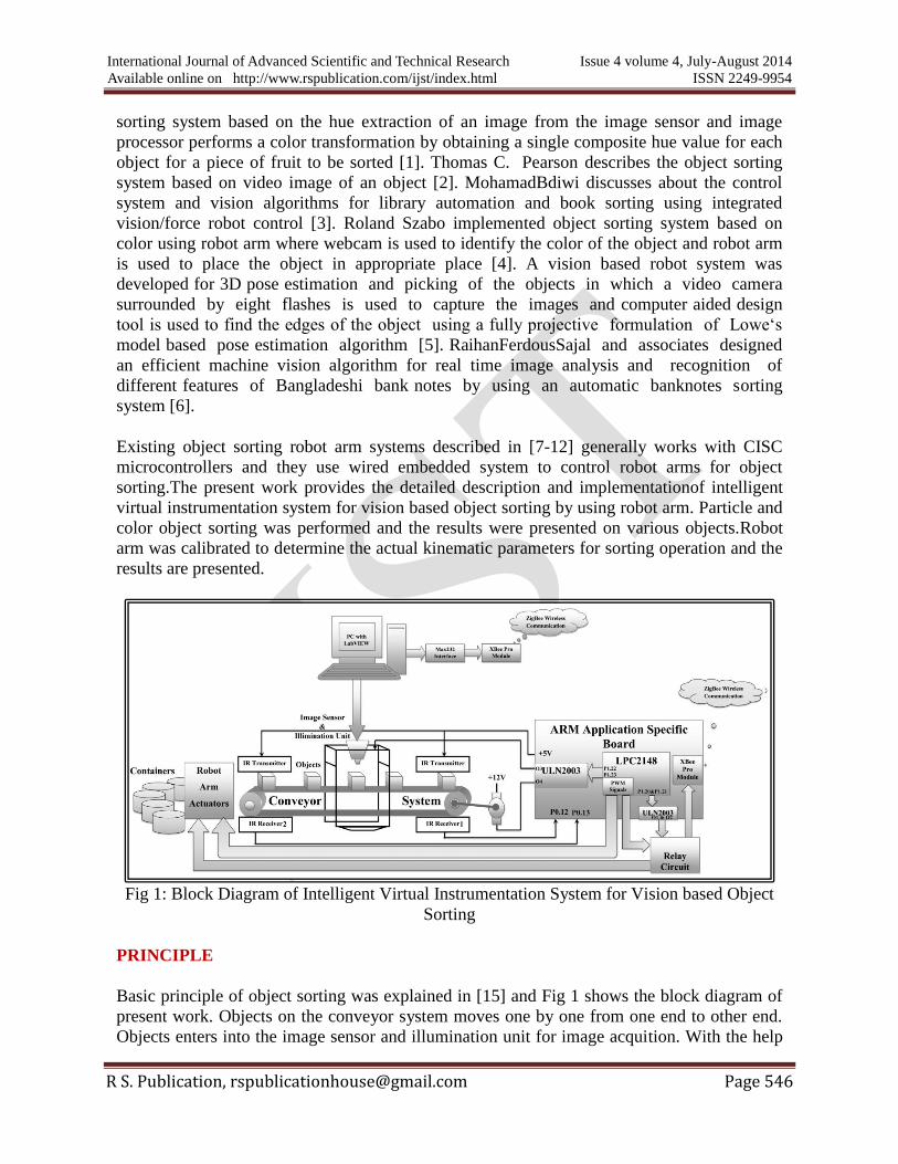
Fig 1: Block Diagram of Intelligent Virtual Instrumentation System for Vision based Object
Sorting
PRINCIPLE
Basic principle of object sorting was explained in [15] and Fig 1 shows the block diagram of
present work. Objects on the conveyor system moves one by one from one end to other end.
Objects enters into the image sensor and illumination unit for image acquition. With the help

International Journal of Advanced Scientific and Technical Research Issue 4 volume 4, July-August 2014
Available online on http://www.rspublication.com/ijst/index.html ISSN 2249-9954
R S. Publication, [email protected] Page 547
of sensors, conveyor belt engages for a while by stopping the motor, when objects enter into
the illumination unit. Image is acquired and sent to PC for classification. Software package in
the PC classifies the image and calculates the robot arm joint angles by evaluating Inverse
Kinematics (IK) based on the object in the image. Joint angles were transmitted by using
wireless communication to the microcontroller. Microcontroller receives the joint angles and
converts the joint angles into corresponding PWM signals to run the robot arm actuators for
end-effector positioning. Robot arm grasps, picks and places the objects in the containers
depending on the class of the object.
Fig 2: Mechanical Drawing of Conveyor System
HARDWARE FEATURES
Hardware features of the present work contains of
Image Sensor
PC
LPC2148 ARM Application Specific Board
Robot Arm
Relay Circuit
Conveyor System
Illumination Unit
Hardware details about image sensor, PC, LPC2148 ARM application specific board,robot
arm and relay circuit was explained in [14, 16]. Conveyor system and illumination unit were
explained in subsequent sections.

International Journal of Advanced Scientific and Technical Research Issue 4 volume 4, July-August 2014
Available online on http://www.rspublication.com/ijst/index.html ISSN 2249-9954
R S. Publication, [email protected] Page 548
CONVEYOR SYSTEM
A conveyor system is a mechanical assembly unit or a mechanical handling system which
moves the objects from one place to another place. It allows speed and efficient way of
transporting wide variety of materials in material handling and packaging industries. In the
present work a conveyor system was designed and controlled. It consists of belt, IR sensors
and DC motor.
Idlers form the supports for the carrying and return of the belt. A structure supports and
preserves the alignments of the idlers, pulleys and supports the driving machinery 12VDC
motor. Pulleys supports and moves the belt to control its tension.
Fig 3: Mechanical Drawing of Illumination Unit
The body of the conveyor system was designed with 4mm thickness and 24x32sqrinch white
acrylic sheet. The mechanical design on the sheet was shown in Fig 2. With the help of a
computerized wood carving machine the sheet was carved accurately for the conveyor system
parts.In the figure (a) & (b) are 24inchx83mm idlers with four grooves of length 92mm. (c) &
(d) are structures of 32inchx100mm size. Each structure has 8mm holes at two ends for
pulleys. They contain 4mm rectangular shaped holes to fit the grooves of the idlers in (a) &
(b) and 5.2mm holes on the top of each structure to fix the IR sensors. In (d) it contains a
12mm hole for fixing 12VDC motor with the help of (e). Four5mm bearings were fixed to the
wood pulleys to rotate freely without fiction. Two idlers are fixed so as to fit into the
structures by keeping the 5.2mm holes to the top. Two sets of IR transmitter and IR receiver
are fixed at each end of the structure to stop the DC motor whenever the object is interrupted

International Journal of Advanced Scientific and Technical Research Issue 4 volume 4, July-August 2014
Available online on http://www.rspublication.com/ijst/index.html ISSN 2249-9954
R S. Publication, [email protected] Page 549
in between transmitter and receiver, hence acts as object sensors. One set of sensorstops the
DC when the object enters into the illumination unit and another set is used only at starting
point.
Belt forms the moving and supporting surface on which the conveyed objects rides. It is the
synthetic and tactive element that should selected considering the object to be transported.
Hence a 3inch elastic belt was used for object transportation. Conveyor system was controlled
by using LPC2148 ARM microcontroller.
ILLUMINATION UNIT
Illumination unit plays a vital role in the classification process to acquire the imges with
constant light intensity. Illumination unit used in the present work was desinged by using a
4mm thickness and 30x18sqrinch white acrylic sheet.Fig 3 shows the mechanical drawing on
the sheet and the sheet was sliced accurately by using wood carving machine. As shown in
Fig 3, (a) & (b) are two stand slices with 330x200sqrmm height and length. Each stand has
four 53x4mm grooves and four 55mmx5mm rectangular holes to fit with the side walls of the
unit. (c) & (d) are the side walls of the unit with 140x100mm length and height that contains
two rectangular holes each.(f) & (g) are the bottom supporters with 210x50mm length and
breadth. (h), (i), (j) & k are the side supporters with 35mm breadth and 230mm length that
was sliced in a training fashion for the stability of illumination unit and each one has two
53x4mm grooves.
Fig 4: Front Panel of the Present work
Image sensor was equipped with illumination unit to capture clear and optimal images
with ease. Illumination unit consists of 12V LEDs which are connected in series and fixed in
such a way that the lightingwas focused on the object. 35 LEDs are connected with 7 arrays
and each array contains three LEDs and 3 current limiting resistors.

International Journal of Advanced Scientific and Technical Research Issue 4 volume 4, July-August 2014
Available online on http://www.rspublication.com/ijst/index.html ISSN 2249-9954
R S. Publication, [email protected] Page 550
SOFTWARE FEATURES
Software features of the present work have been divided into two parts LabVIEW and
embedded ‘C’. LabVIEW was programmed on PC and performs the classification, robot arm
IK and ZigBee transmission procedures. Embedded ‘C’ was programmed for LPC2148 and
performs ZigBee reception, conveyor system control, illumination unit control and PWM
procedures.
Fig 5: LabVIEW Block Diagram of the Present Work
LABVIEW and Embedded ‘C’
LabVIEW program contains front panel and block diagram. Front panel is a kind of Graphical
User Interface (GUI) which acts as interface between user and the block diagram of
LabVIEW. It contains inputs control elements and output indicator/display elements. Block
diagram contains the actual program which guides the front panel inputs through outputs. Fig
4 shows the front panel of the present work contains Sorting Type, Particle Type, File Path,
XBee Port Setting, Image Out, STOP, Invalid Position, Class, Robot Arm Movement, thetab,
theta1, theta2, theta3, thetaw and thetag.

International Journal of Advanced Scientific and Technical Research Issue 4 volume 4, July-August 2014
Available online on http://www.rspublication.com/ijst/index.html ISSN 2249-9954
R S. Publication, [email protected] Page 551
Sorting Type and Particle Type are front panel silver control elements. Sorting Type is used to
select type of sorting among Particle & Color and if Sorting Type is Particlethen Particle
Type is used to select the type of particle among nuts, bolts & electronic spares. If Sorting
Type is color then no need to select the Particle Type.File Path is the control element which is
used to feed the classifier file as input to the Classification VI. If Sorting Type is particle then
select particle classifier file else select color classifier file. Image Out shows the image under
inspection. STOPand invalid Position are the Boolean variables used to stop the classification
process when robot arm end-effector position goes invalid. Robot Arm Movementis3D Picture
Control VI which is used to observe therobot arm transformation in simulation.thetab, theta1,
theta2, theta3, thetaw and thetag are 64-bit numeric indicators used to display the joint angles
of the robot arm.
Fig 6: Flow chart (a) LabVIEW (b) LPC2148 Microcontroller
Fig 5 shows the LabVIEW block diagram of the present work. Total block diagram was
designed and divided into sub programs such as Acquisition, Particle, Color, XBee_R,
XBee_W, Robot Arm, Robot Arm reset, Grasping, Picking, Transit and Placing. Acquisition
acquires the image from the image sensor through USB. Particle is the classification program
for all particle types. Particle classification was performed by keeping lower thresholding
value as 10 and higher thresholding value as 254. Color is the classification program for color

International Journal of Advanced Scientific and Technical Research Issue 4 volume 4, July-August 2014
Available online on http://www.rspublication.com/ijst/index.html ISSN 2249-9954
R S. Publication, [email protected] Page 552
bottles classification. Color classification was performed by keeping luminous value on and
resolution in medium. Particle and color classification was explained in [17]. XBee_R and
XBee_Ware ZigBee read and write programs. XBee_R reads the Ctrl_Pin status from
microcontroller and XBee_Wwrites robot arm joint angles followed by Ctrl_Pin status to the
microcontroller. XBee_R and XBee_W were explained in [18]. Robot Arm reset, Grasping,
Picking, Transit and Placing are the movements of the robot arm. Each movement has its own
coordinate system and depending on the Class coordinate variables varies. Robot Arm
evaluates the IK model of the robot arm and displays the robot arm movement on the front
panel. IK model and implementation was explained in [16].
To initialize the process of sortingtwo objects are placed manually, one in the illumination
unit and other at IR2. Fig 6: (a) shows the flow chart of the LabVIEW program. It starts by
selecting/setting the inputs and file path. Here inputs refer to the Sort Type, Particle Type,
XBee Settings and File Path refers to the classifier file path. LabVIEW control executes the
XBee_R to read the Ctrl_Pin from LPC2148 and waits until it is equal to 1.Then most recently
captured image was acquired by the Acquisition program. Classification process starts
depending up on the inputs and classifies the object in the image. Depending upon the class
name of the object robot arm movements such as reset, grasping, positioning, transit and
placing is going to feed on by one as inputs to IK model. IK model calculates the correct joint
angles, transmits the Ctrl_Pin as 0 and joint angles.
Table1. Actual positions of the robot arm end-effector for the present work
Fig 6: (b) shows the flow chart of the embedded ‘C’ program on LPC2148 microcontroller.
The program first initializes all the peripherals required for the current operation such as
GPIO ports, UART and PWM channels. As shown in Fig 1, conveyor system uses two pairs
of IR sensors to sense the object on the belt. Two IR transmitters and two IR receivers are
used. IR transmitter was supplied with 5V to transmit IR light rays and IR receiver
continuously obtains them. These rays are interrupted when object was presented between
them. Here IR receivers provide zero voltage when there is an object, keeping this into
consideration IR receiver2 was used as sensor. IR receiver1 and IR receiver2 (as designated in
Fig 1) are used to control the conveyor system and LED arrays in the illumination unit. In the
present work only IR receiver2 (IR2) is used and IR receiver1 kept idle for feature use.
LPC2148 reads the signal from IR2 checks whether the output is equal to zero or not. If yes
12V DC motor will goes off and LED array goes on from P1.22 and P1.23 of LPC2148
through ULN2003. Then Ctrl_Pin is set to 1, select ZigBee communication through relay
circuit by setting P1.20 & P1.21 of LPC2148 through ULN2003 and sent to PC. Wait until PC

International Journal of Advanced Scientific and Technical Research Issue 4 volume 4, July-August 2014
Available online on http://www.rspublication.com/ijst/index.html ISSN 2249-9954
R S. Publication, [email protected] Page 553
completes the classification operation and sends back the Ctrl_Pin and joint angles. PC resets
the value of Ctrl_Pin to zero and sends it along with the calculated joint angles. Joint angles
are converted into PWM signals. Select two PWM channels (PWM4, PWM6) by resetting
P1.20 & P1.21 relay circuit. Calculated PWM signals were sent to for robot arm end-effector
was controlling. Then loop continues to the next object. Embedded ‘C’ for wireless robot arm
control was explained in [16].
RESULTS AND DISCUSSIONS
From the comparative study of nuts, bolts and color bottles it is known that for nuts and bolts
classification NN (Nearest Neighbor) algorithm and Sum (Manhattan) Distance metric, for
electronic spares NN and Euc (Euclidean) distance metric yields the best results and for color
bottlesMMD (Minimum Mean Distance) and Sum distance are used in the present work.
Hence the classifier file for each category was trained by using the above constraints.
Table2. ThetaG and ThetaB Values for each category
IK model for the present robot arm for various end-effector positions in its workspace was
explained in [16]. But to sort the objects into the containers, robot arm was calibrated to
determine the actual kinematic parameters for the present work. The operations of the robot
arm are reset, grasping, picking, transit and placing. Reset is the position of the robot arm
end-effector near to the object on the conveyor system with open gripper. Grasping is
operation for the end-effector to grab the object. Lifting the object was done with picking
operation. Transit is the operation where robot arm travels from conveyor system to the
container. Releasing the object into the container is done with placing. Table1 shows the
calibrated values of all operations of robot arm for 5mm nut. Values of ThetaG and ThetaB
vary depending on the type of object. Table2 (a) and (b) shows the values of ThetaG and
ThetaB for each category.
Object Type ThetaG ThetaB Object Type ThetaG ThetaB
4mm Nuts 12.8 15 Battery 83.2 20
5mm Nuts 16 45 POT 19.2 60
6mm Nuts 19.2 75 Relay 48.6 100
10mm Nuts 32 105 Toggle Switch 51.5 140
12mm Nuts 38.4 135 Blue 140 30
15mm Nuts 48 165 Cyan 140 90
4mm Bolts 12.8 20 Green 140 150
5mm Bolts 16 60 Orange 140 30
6mm Bolts 19.2 100 Pa Green 140 90
10mm Bolts 32 140 Pink 140 150
12mm Bolts 38.4 180 Red 140 30
Sky Blue 140 90
Yellow 140 150(a)
(b)

International Journal of Advanced Scientific and Technical Research Issue 4 volume 4, July-August 2014
Available online on http://www.rspublication.com/ijst/index.html ISSN 2249-9954
R S. Publication, [email protected] Page 554
In the present work experimentation has been conducted on 420, 350, 280 and 63real time
images of nuts, bolts, electronic spares and color bottles respectively wereselected by the
manual experts. Black colored nuts and bolts, multicolored electronic spares were selected to
compare the sorting method. From Table 3 it isshows the object sorting results for the four
categories.
Total 70 objects ofeach category 4mm, 5mm, 6mm, 10mm, 12mm and 15mm diameter nuts
are used for sorting. 68, 65, 64, 66, 63 and 70 nuts of 4mm, 5mm, 6mm, 10mm, 12mm and
15mm were sorted correctly while 2 nuts of 4mm were sorted to 10mm container, 3 and 2
nuts of 5mm were sorted to 4mm and 10mm containers, 4 and 2 nuts of 6mm were sorted to
5mm and 12mm containers, 1 and 3 nuts of 10mm were sorted to 4mm and 5mm containers,
1, 5 and 1 nuts of 12mm were sorted to 4mm, 5mm and 6mm containers respectively.
Table3. Object Sorting Results for Nuts, Bolts, Electronic Spares and Color Bottles
Total 70 objects of each category 4mm, 5mm, 6mm, 10mm, and 12mm diameter and 1inch
bolts are used for sorting. 70, 65, 70, 57 and 66bolts of 4mm, 5mm, 6mm, 10mm and 12mm
were sorted correctly while 4 and 1bolts of 5mm were sorted to 10mm and 12mm containers,
8, 4 and 1bolts of 10mm were sorted to 12mm, 5mm and 6mm containers, 4 bolts of 12mm
were sorted to 10mm container respectively.
Fig 7: Comparison of Existing and Proposed Sorting Method
Total 70 objects of each category Battery, POT, Relay and TS electronic spares are used for
sorting. 53, 64, 55 and 51 electronic spares of Battery, POT, Relay and TS were sorted
correctly while 4, 7 and 6 Batteries were sorted to POT, Relay and TS containers, 1 and 5

International Journal of Advanced Scientific and Technical Research Issue 4 volume 4, July-August 2014
Available online on http://www.rspublication.com/ijst/index.html ISSN 2249-9954
R S. Publication, [email protected] Page 555
POTs were sorted to Relay and TS containers, 2 and 13 Relays were sorted to POT and TS
containers, 1, 4 and 14 TSs were sorted to Battery, POT and Relay containers respectively.
Total 7 color bottles of each color blue, cyan, green, orange, parrot green, pink, red, sky blue
and yellow were used for sorting. Only three colors were chosen to sort at a time and sorting
process was performed three times for total nine colors. 6, 7, 6, 7, 7, 7, 7, 6 and 7 were sorted
correctly while 1 blue bottle was sorted to cyan bottle container, 1 green bottle was sorted to
parrot green bottle container and 1 sky blue bottle was sorted to blue bottle container.
Table3 shows the object sorting results for all categories. Where T = Total number of Objects,
C = Correctly Sorted Objects, I = Incorrectly Sorted Objects and A = Accuracy (%). Table3
shows the correctly sorted objects, incorrectly sorted objects along with the accuracy
percentages for both manual sorting method and proposed sorting.
CONCLUSION In this paper overall wireless object sorting system was designed and implemented by using
virtual instrumentation and classification techniques. Fig 7 shows the comparison results for
manual sorting method and proposed method with total number of objects. It shows that nuts,
bolts and color sorting has high accuracy than electronic spares sorting for the proposed
method. This is because nuts and bolts are black in color while electronic spares are in color
hence nuts and bolts were well suited and electronic spares are not suited for image
thresholding. Nuts and bolts were classified depending on the circularity featureand degree of
elongation feature while electronic spares were classified based on features explained in
[17].From the practical experimentation of present work it is known that the calibrated robot
arm end-effector positioning was more accurate than uncalibrated one [16].In the calibration,
±1cm precision of robot arm was reduced by determining the actual kinematic parameters and
adjusting the joint angles through embedded ‘C’ programming.Classification algorithms in
real time implementation shows more accuracy than [14, 17].
REFERENCES [1] Yang Tao, Method and Apparatus for Sorting Objects by Color, U.S. Patent 5
339 963, Aug 23, 1994.
[2] Thomas C. Pearson, Machine Vision Apparatus and Method for Sorting Object, U.S.
Patent 5 703 784, Dec 30, 1997.
[3] Bdiwi, M.; Suchy, J., Robot control system with integrated vision/force feedback for
automated sorting system,Technologies for Practical Robot Applications (TePRA),
IEEE International Conference, 23- 24 April 2012, p p.31,36.
[4] Szabo, R.; Lie, I., Automated colored object sorting application for robotic arms,
Electronics and Telecommunications (ISETC), 2012 10th International Symposium
, pp.95,98, 15-16 Nov. 2012.
[5] AmitAgrawal, Yu Sun, John Barnwell, Ramesh Raskar, Vision Guided Robot
System for Picking Objects By Casting Shadows, International Journal of Robotics
Research, vol. 29 no. 2-3, pp.155-173, February 2010.
[6] B.Gabrya, L. Petrakieva; Combining labeled and Unlabelled data in the design of
pattern classification systems, International Journal of Approximate Reasoning ,
2004.

International Journal of Advanced Scientific and Technical Research Issue 4 volume 4, July-August 2014
Available online on http://www.rspublication.com/ijst/index.html ISSN 2249-9954
R S. Publication, [email protected] Page 556
[7] Vishnu R. Kale, V. A. Kulkarni, Object Sorting System Using Robotic Arm,
International Journal of Advanced Research in Electrical, Electronics and
Instrumentation Engineering, Vol. 2, Issue 7, July 2013.
[8] DharmannagariVinay Kumar Reddy, Sorting of Objects Based on Colour By pick And
Place Robotic Arm and with Conveyor Belt Arrangement, Int. J. Mech. Eng. & Rob.
Res. 2014, Vol. 3, No. 1, January 2014.
[9] Vishnu R. Kale, V. A. Kulkarni, Automation of Object Sorting System Using Pick &
Place Robotic Arm & Image Processing, Proceedings of 3rd IRAJ International
Conference, 5th January 2014, Mumbai, India. ISBN: 978-93-82702-51-1.
[10] N.I. Giannoccaro, L. Spedicato, A. Lay-Ekuakille, A Smart Robotic Arm For
Automatic Sorting of Objects With Different Tags, 4th Imeko TC19 Symposium on
Environmental Instrumentation and Measurements Protecting Environment, Climate
Changes and Pollution Control, June 3-4, Lecce, Italy, 2013.
[11] Vikas S. Zilpe, ShahrukhPathan, Pranita Choudhary, A Smart Robotic Arm for
Automatic Sorting Of Objects With Different RFID Tags, Discovery, 2014, 18(54), pp:
111-114, www.discovery.org.in.
[12] Monal S. Telgote, Ganesh S. Sable, Object Sorting System in Matlab using Robotic
Arm, International Journal of Science and Engineering Investigations vol. 2, issue 22,
November 2013.
[13] Vindhya Devalla, Dr. Rajesh Singh, Amit Kumar Mondal, VivekKaundal, Design and
Development of Object Recognition and Sorting Robot for Material Handling in
Packaging and Logistic Industries, International Journal of Science and Advanced
Technology (ISSN 2221-8386) Volume 2 No 9 September 2012.
[14] C. Chandra Mouli, P. Jyothi and K. Nagabhushan Raju, Comparative Study of
Supervised Classification Algorithms for WOSRAS, International Journal of Advanced
Research in Electrical, Electronics and Instrumentation Engineering (An ISO 3297:
2007 Certified Organization) Vol. 3, Issue 2, February 2014, pp: 7188 – 7193.
[15] P. SudhakaraRao, A. Gopal, R. Revathy and K. Meenakshi, Colour Analysis Of Fruits
Using Machine Vision System For Automatic Sorting And Grading, Journal of
Instrumentation Society of India 34(4), pp. 284-291. [16] C. Chandra Mouli, P. Jyothi and K. Nagabhushan Raju,Modeling and Implementation
of Wireless Embedded Robot Arm for Object Sorting, IOSR Journal of Electrical and
Electronics Engineering (IOSR-JEEE), Volume 9, Issue 4 Ver. III (Jul – Aug. 2014), PP
35-44. e-ISSN: 2278-1676,p-ISSN: 2320-3331.
[17] Design, Implementation and Comparative Study of Supervised Classification
Algorithms for Object Sorting [In Press]
[18] C. Chandra Mouli, P. Jyothi, K. Nagabhushan Raju, C. Nagaraja, T. Bheemalingaiah
and M. Ashok Kumar, Implementation of serial communication in LabVIEW to
interface with 8051 based microcontroller, Research Journal of Engineering &
Technology, Vol.3. Issue.4, pp.7-9, ISSN 0974-2824.
[19] U.S. Ragupathy, B. Venkatesan and P.T. Sasikkannan, Fault Identification and
Classification in Textile Web Materials using Particle Analyzer, 3rd International
Conference on Intelligent Computational Systems (ICICS'2013) April 29-30, 2013
Singapore. pp: 63-66.