design and implementation of an iec 61850 gateway...
TRANSCRIPT
Design and Implementationof an IEC 61850 gateway for
PLC Systems
Jonas Lidén
Master ThesisStockholm, Sweden 2006
XR-EE-ICS 2006:021
Abstract This master thesis presents the result of an investigation and testing of IEC 61850 introduction into Vattenfall Vattenkraft AB’s technical systems for turbine controllers. The work started with an investigation of today’s automation products with focus on station bus communication. Today Vattenfall Vattenkraft AB are modernising their automation products in many of their hydro power plants, and the turbine controllers are developed by SwedPower AB on standard PLC’s from Siemens Automation and Drives. Therefore the product focus has been PLC systems from Siemens for compatibility with the modern turbine controller used today. The initial investigation provided a few alternatives for how to implement and test an IEC 61850 interface for turbine controllers, one of these alternatives were selected for implementation and tested regarding communication on the station bus and for a few data values. The report describes the implementation and the results of the testing. Today there are no PLC’s capable of communicating in accordance to IEC 61850, the interface implemented and tested during this master thesis work provides an interface based on an industrial PC gateway for PLC’s to communicate using the IEC 61850 standard.
Keywords IEC 61850, PLC, Simatic S7, AX-S4 MMS, Gateway.

Preface
This technical report is the result of my master thesis work that has been conducted on Vattenfall Utveckling AB. The supervisors for this work are Mr. Anders Johnsson from Vattenfall Utveckling AB and Mr. Lars Nordström from the department of Industrial Information and Control Systems at the Royal Institute of Technology. Mr Per-Anders Nordlander from Vattenfall Vattenkraft AB and Mr Henrik Wiechel from SwedPower AB have given many valuable opinions and implementation help regarding the functions and testing of the IEC 61850 interface.
This report is in first hand written for people with knowledge of the electric power industry already familiar with the many terms used in substations and hydro power plants. Readers not introduced to the standard of IEC 61850 are recommended to read Appendix 1 - IEC 61850 after the initial chapter of IEC 61850 found in chapter 3.1.
I hope that all readers find it valuable and interesting.
Stockholm, 06-03-28
Jonas Lidén
4
Abstract ..................................................................................................................................... 2 Preface ....................................................................................................................................... 3 1 Introduction ...................................................................................................................... 7
1.1 Purpose ....................................................................................................................... 7 1.2 Background ................................................................................................................ 7 1.3 Outline of the report ................................................................................................... 8
2 Research Method............................................................................................................ 10 2.1 Goals......................................................................................................................... 10 2.2 Scope of the study .................................................................................................... 10 2.3 Problem description.................................................................................................. 10 2.4 Research Problem..................................................................................................... 11 2.5 Implementation guidelines ....................................................................................... 11 2.6 Investigation path ..................................................................................................... 12 2.7 Literature .................................................................................................................. 12
3 Communication solutions .............................................................................................. 14 3.1 IEC 61850 Overview................................................................................................ 14 3.2 OPC .......................................................................................................................... 17 3.3 MMS......................................................................................................................... 18
4 Product information....................................................................................................... 20 4.1 Siemens S7 PLC....................................................................................................... 20 4.2 ABB AC 800M PLC ................................................................................................ 23 4.3 Siemens Simatic Microbox 420 ............................................................................... 24 4.4 Tamarack software stack for embedded systems ..................................................... 25 4.5 MMS-EASE Lite...................................................................................................... 25 4.6 AX-S4 MMS ............................................................................................................ 26 4.7 SOFTNET for PROFIBUS....................................................................................... 27
5 Design alternatives ......................................................................................................... 28 5.1 Implementation on ABB PLC system:..................................................................... 29 5.2 Implementation on Siemens PLC system: ............................................................... 30 5.3 PC Gateway design .................................................................................................. 30 5.4 Rejected alternatives ................................................................................................ 31
6 Design proposal .............................................................................................................. 33 6.1 Overview .................................................................................................................. 33 6.2 Hardware: ................................................................................................................. 33 6.3 Software ................................................................................................................... 34 6.4 Design specifications................................................................................................ 34
7 Testing the interface....................................................................................................... 37 8 Results ............................................................................................................................. 40 9 Future work .................................................................................................................... 41
9.1 Implemented interface.............................................................................................. 41 9.2 Future products......................................................................................................... 42
10 References to external experts .................................................................................. 44 11 References for articles and manuals......................................................................... 45 Appendix 1 - IEC 61850........................................................................................................... 1
The ACSI-model .................................................................................................................... 4 Data modelling ....................................................................................................................... 7 Communication services ...................................................................................................... 17 Client/Server communication............................................................................................... 21 Reporting.............................................................................................................................. 25 Logging ................................................................................................................................ 28

5
Control class model .............................................................................................................. 30 Comparison of the data access methods............................................................................... 30 Communication mappings.................................................................................................... 31
Appendix 2 - Definitions. ......................................................................................................... 1 Logical Nodes ........................................................................................................................ 1 Data Objects ........................................................................................................................... 2
6
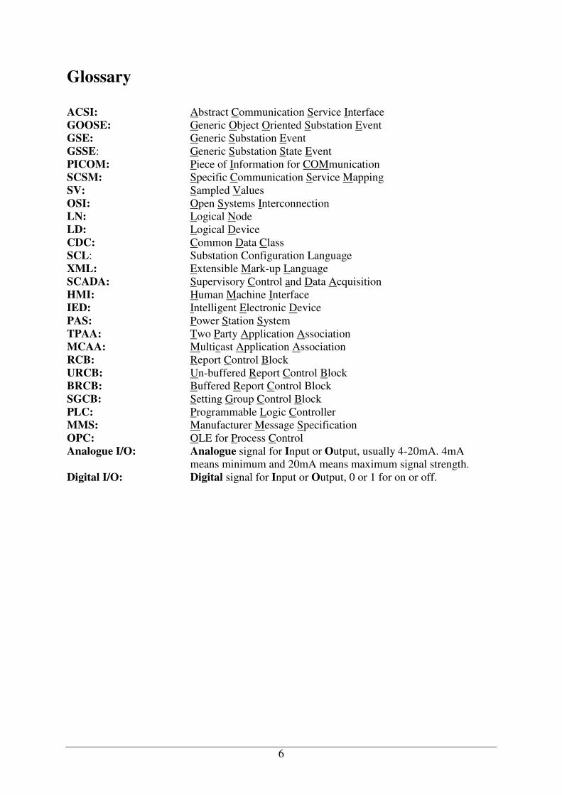
Glossary ACSI: Abstract Communication Service Interface GOOSE: Generic Object Oriented Substation Event GSE: Generic Substation Event GSSE: Generic Substation State Event PICOM: Piece of Information for COMmunication SCSM: Specific Communication Service Mapping SV: Sampled Values OSI: Open Systems Interconnection LN: Logical Node LD: Logical Device CDC: Common Data Class SCL: Substation Configuration Language XML: Extensible Mark-up Language SCADA: Supervisory Control and Data Acquisition HMI: Human Machine Interface IED: Intelligent Electronic Device PAS: Power Station System TPAA: Two Party Application Association MCAA: Multicast Application Association RCB: Report Control Block URCB: Un-buffered Report Control Block BRCB: Buffered Report Control Block SGCB: Setting Group Control Block PLC: Programmable Logic Controller MMS: Manufacturer Message Specification OPC: OLE for Process Control Analogue I/O: Analogue signal for Input or Output, usually 4-20mA. 4mA
means minimum and 20mA means maximum signal strength. Digital I/O: Digital signal for Input or Output, 0 or 1 for on or off.
7
1 Introduction
1.1 Purpose Vattenfall AB Vattenkraft’s purpose with the initiation of this master thesis is to investigate the prerequisites and consequences of an IEC 61850 introduction in their automation systems. In line with Vattenfall AB’s renewal strategies the communication interface of IEC 61850 needs to be implemented, tested and evaluated in today’s generation of PLC-systems before any further decisions can be made. Important feedback that this master thesis should provide is both technological and economical aspects of the IEC 61850 introduction.
1.2 Background Communication standards in the electric power industry provide a basis for an efficient exchange of essential commands, status information and measurement data. As the number of signals increased, existing solutions have reached their limits [10]. In 1994 EPRI/IEEE started a work UCA2 (utility communication architecture), with focus on the station bus. In 1996 IEC TC57 (technical committee 57) began work on IEC 61850 to define a station bus. This led to a combined effort in 1997 to define an international standard that would merge the work of both groups. The result is the current IEC 61850 specifications. In 2004 a new group within IEC TC57/WG 18 started the work to define the use of 61850 in hydro power plants. The WG (working group) 18 extension makes it possible to use IEC 61850 for hydro power plants. Vattenfall AB is an active member of this workgroup and holds the chairman role. Today Vattenfall are using different solutions for every hydro power station, each solution is almost unique. This is because no concept has been used when the stations were built and because of different technology where available when the stations where modernised. There is a need for standardising the communication in hydro power plants and IEC 61850 could prove to be the way out of a vendor-specific environment just in line with Vattenfall ABs renewal plans. The following description of how the modern stations communication system is built is generic but provides a god foundation for understanding it. On the top of the control system is the station computer, which deals with functions concerning the whole station and all the units, like water flow in and out of the station. This computer also handles the communication with the plants control room and communications with central control stations. Below, there is the unit computer that controls more local events for each unit, this computer also collects measurements from the more local controllers and passes them on upwards in the communication system. To the unit computer more PLC systems are connected that each handles different tasks in the process, like magnetisation, turbine control and voltage control. Each of these PLCs is connected to the process either via hardwired I/O signals or via a field bus. The interface between the local controllers and the unit computer is the station bus. The communication on the station bus level is today not standardised and Vattenfall uses different solutions. In the older power plants there is no station bus, all signals are hardwired between the PLCs and unit computer [9].

Introduction
8
Figure 1: Vattenfall system environment Vattenfall uses controllers from different vendors in the power stations. Today there is one station with a whole concept using Siemens as station/unit computer and turbine controller and voltage controller. The same is true for ABB, one station uses a whole concept solution from ABB. Furthermore about ten PLCs from Siemens are installed as turbine controllers. Also one turbine controller is implemented on a PLC from GE Fanuc. Today Vattenfall are installing turbine controllers implemented on standard industrial PLC systems delivered by SwedPower AB. The controller hardware is based on the Siemens Simatic S7-300, and the controller application is developed by SwedPower AB. This is the turbine controller that is intended to be used in the nearest future in all upgrades for hydro power plants. Vattenfall needs an interface for IEC 61850 in turbine controllers since the modern generation of power distribution equipment will be using this interface. Since the programming methods for PLC systems follow the standard IEC 61131-3 and not IEC 61850, it is of interest to study how to implement IEC 61850 in an environment of a PLC.
1.3 Outline of the report Chapter 1 - Introduction is intended to focus the reader on the right problem and provides a background for the rationale behind the initiation of the master thesis. Chapter 2 - Research Method provides information regarding the goals, methods used and literature studied in this work. Chapter 3 - Communication solutions provides a basis for understanding IEC 61580 that is the standard investigated and tested in this work and other communication solutions of interest in this work. More information regarding IEC 16850 can be found in Appendix 1 - IEC 61850. Chapter 4 - Product information describes the hardware and software products that have been of interest during the investigation of suitable solutions to the research problem. Chapter 5 - Design alternatives presents the options that were presented at a meeting at Vattenfall during December in order to select a suitable design for the IEC 61850 interface. The selected alternative is presented in chapter 6 - Design proposal. The Test and implementation plan and the results for verifying the design is presented in chapter 7 - Testing the interface. Chapter 8 - Results describes the result of the project. Chapter 9 - Future work

Introduction
9
presents the conclusions and any future work that might be of interest for the design proposal, and also a discussion of future products that might be of interest.

10
2 Research Method This chapter presents the objectives for the study and the research method for achieving the goals for this project. This technical report is in first hand to be considered as a feasibility study that addresses the problem defined in chapter 2.4.
2.1 Goals The overall goal of this project is to provide a basis for future decisions as part of the renewal strategies of Vattenfall Vattenkraft AB. The main task of this master thesis work is to investigate software and hardware that enables messaging on station bus level using IEC 61850 as protocol, focusing on turbine controllers. The secondary task if the investigation has a positive result is to implement and test the messaging on station bus level specified in the communication interface of IEC 61850.
The objective is to deliver a technical report that summarises the result and conclusions of the investigation, implementation and testing of IEC 61850 in PLC-systems.
• Including a software and hardware investigation of PLC and communication products from different vendors that are suitable for using in an implementation of an IEC 61850 interface.
• Including one or more design proposals with a test plan.
• Including implementation and testing results from one of the design proposals.
2.2 Scope of the study Due to the fact that the focus of this study will be set on communication for turbine controllers and HMI systems a natural restriction will be that only communication on station bus level will be investigated. A restriction during the implementation is that only one or few of the logical nodes specified in IEC 61850 will be implemented and tested, and only the read/write service will be implemented and tested.
2.3 Problem description The main goal with this master thesis in the project specification was set to investigate solutions for enabling an IEC 61850 interface for PLC systems. One of the main problems is that IEC 61850 is a standard for sub station automation. Servers are located in distributed devices like switchgear and protection devices. These devices hold their own controlling equipment and are not connected to PLC systems for controlling purposes. In short the IEC 61850 standard is not directly applicable to industrial automation PLCs. Figure 2 below shows typical equipment in a sub station communicating over a station bus.

Research Method
11
Figure 2: Station bus Since a PLC is a multipurpose device and holds no own functionality until the user programs it, the development of a server for PLC systems must be user configurable and relate to some sort of predictable mapping of the data objects in the standard to I/O signals or parameters in the user program. A hydro power plant contains a sub stations but it also contains much more distributed functionality that are located in PLC systems. The standard is therefore not applicable right on. New logical nodes and data objects that can present the information produced in the hydro power plant must be defined. In TC 57 WG 18 of the IEC, work is being done to define these new logical nodes and data objects that would cover all the information presentation needed in hydro power plants. However, this work is not finished until 2007/2008. The logical nodes and the data objects from this new standard are accessible in committee drafts.
2.4 Research Problem In hydro power plants industrial automation PLCs are used to implement turbine controllers. At the same time the IEC 61850 standard has been developed to support substation automation and communication in the power industry. The IEC 61850 standard does however not cover controllers, and manufacturers of industrial automation PLC do not support he IEC 61850 standard.
2.5 Implementation guidelines There are some basic guidelines that have come up during the investigation and they are essential for understanding what products that were investigated, and the design of the alternatives for an interface.
• A design based on a PC gateway is acceptable. • Vattenfall does not wish to develop new products, like communication cards that will
be included in an interface. If it is possible to implement an interface, a vendor will be contracted for any kind of development job.
• Off the shelf products that can be configured and programmed are preferable. • The interface must be possible to use with today’s turbine controller (treg 1.0)
delivered by SwedPower.
Research Method
12
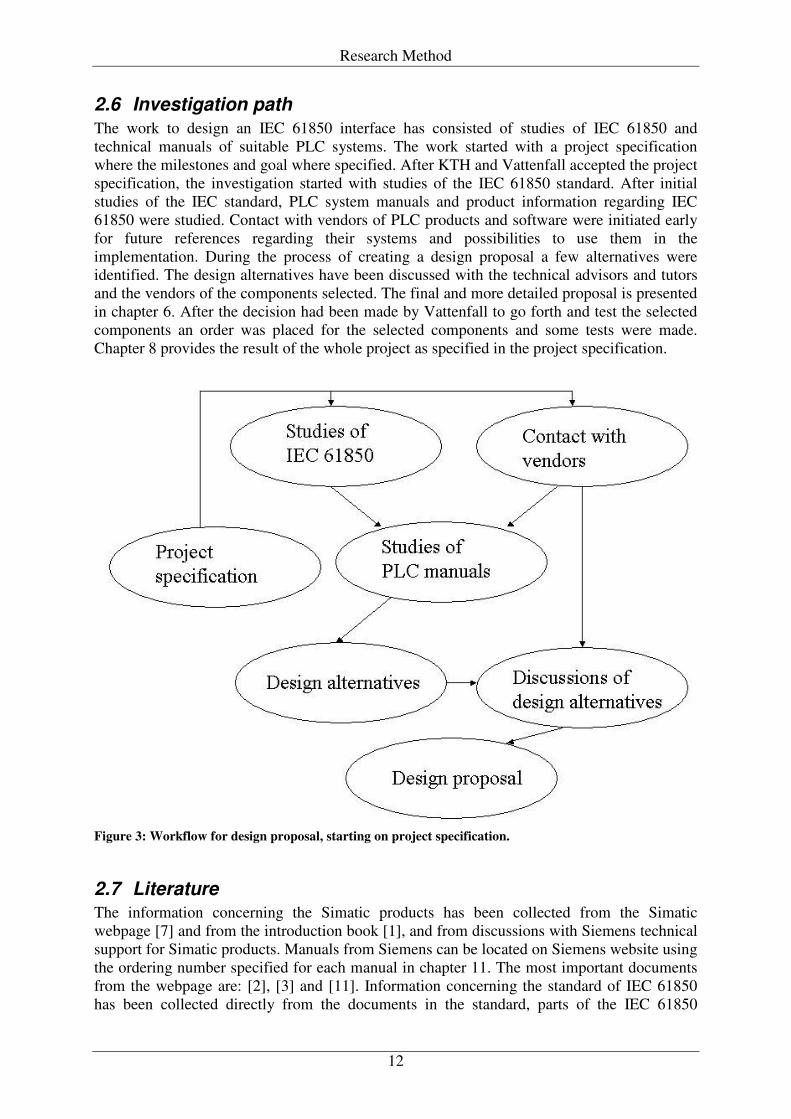
2.6 Investigation path The work to design an IEC 61850 interface has consisted of studies of IEC 61850 and technical manuals of suitable PLC systems. The work started with a project specification where the milestones and goal where specified. After KTH and Vattenfall accepted the project specification, the investigation started with studies of the IEC 61850 standard. After initial studies of the IEC standard, PLC system manuals and product information regarding IEC 61850 were studied. Contact with vendors of PLC products and software were initiated early for future references regarding their systems and possibilities to use them in the implementation. During the process of creating a design proposal a few alternatives were identified. The design alternatives have been discussed with the technical advisors and tutors and the vendors of the components selected. The final and more detailed proposal is presented in chapter 6. After the decision had been made by Vattenfall to go forth and test the selected components an order was placed for the selected components and some tests were made. Chapter 8 provides the result of the whole project as specified in the project specification.
Figure 3: Workflow for design proposal, starting on project specification.
2.7 Literature The information concerning the Simatic products has been collected from the Simatic webpage [7] and from the introduction book [1], and from discussions with Siemens technical support for Simatic products. Manuals from Siemens can be located on Siemens website using the ordering number specified for each manual in chapter 11. The most important documents from the webpage are: [2], [3] and [11]. Information concerning the standard of IEC 61850 has been collected directly from the documents in the standard, parts of the IEC 61850
Research Method
13
appendix has been written by Mr. Berkan Kapkac during his master thesis work at ALSTOM Power AB. Information regarding ABB control systems has been collected from discussions with representatives from ABB’s organisation and from their webpage [8]. Information regarding products from SISCO and Tamarack has been collected from e-mails and telephone calls with the contact persons for respective company or their respective European value added resellers. Unless any other reference is presented in the text, the information presented in chapter 1, 3, 4, 5 and Appendix 1 - IEC 61850 has been collected as described above. All technical experts that have been contacted during this project are listed in chapter 10.
14
3 Communication solutions This chapter describes the basics of the communication solutions of interest in this work. The chapters considering OPC and MMS are meant to orientate the uninitiated reader about the subject, since both MMS and OPC will be mentioned later on in this report. MMS is used as a part of IEC 61850 and should not be of interest to the solution, it is only important that the reader is aware that services in IEC 61850 are performed by the use of MMS services. OPC is of interest since this will be used as a method for communication in one of the solutions presented in this report later on. However both of them can be considered as “underlying” messaging systems as both of these communication solutions are standards and there are functional solutions to communicate in accordance to both of them with PLC:s. The focus should be laying on IEC 61850, as this is the new communication protocol that does not have a solution for PLC systems.
3.1 IEC 61850 Overview A short description of the standard IEC 61850 is given below, a more thoroughly explanation can be found in Appendix 1 - IEC 61850.
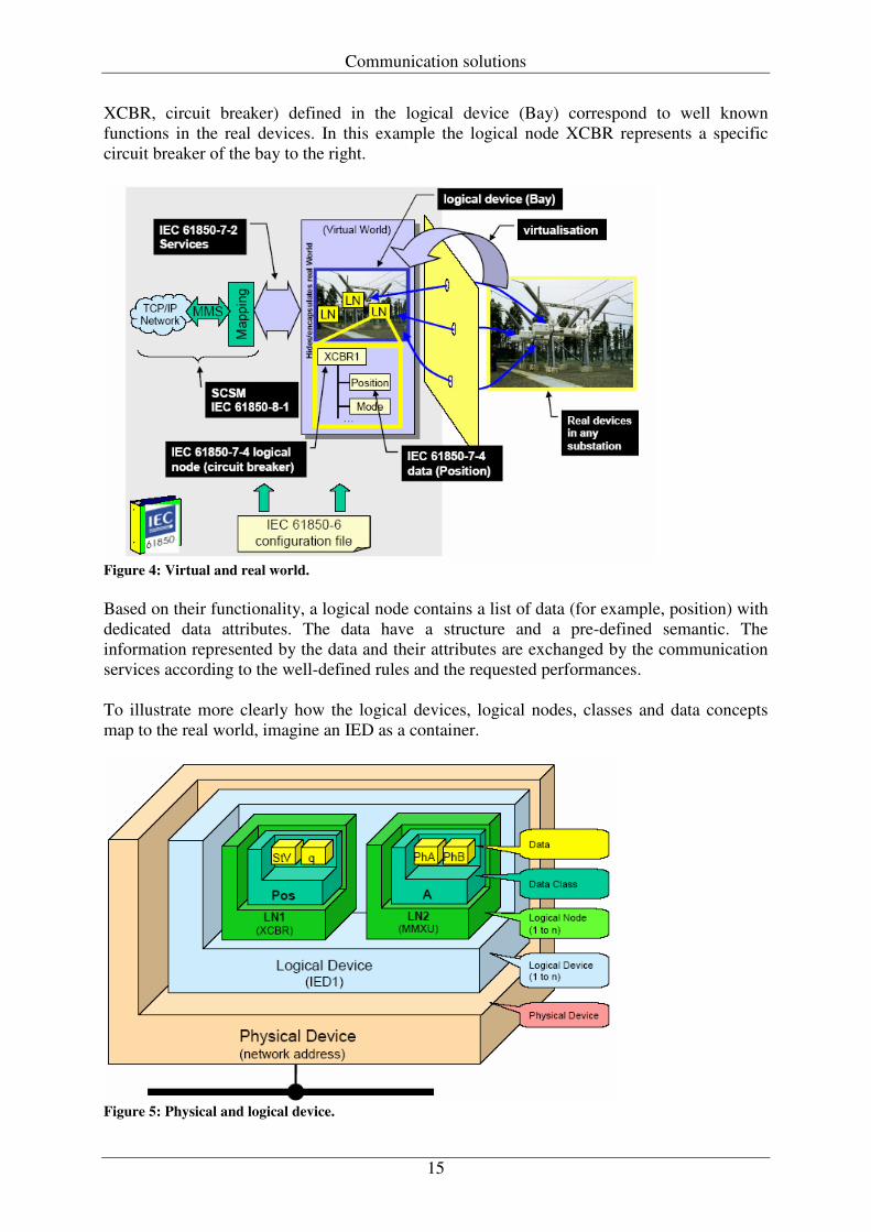
3.1.1 Information model The goal of the IEC 61850 series is to provide interoperability between IED's from different vendors or, more precisely, between functions to be performed in a substation but residing in equipment (physical devices) from different vendors. The information exchange mechanisms rely on well-defined information (data) models. These information models and the modelling methods are at the core of IEC 61850 series. The standard uses the concept of virtualisation. Virtualisation provides a view of those aspects of a real device that are of interest for the information exchange with other devices. Only those details that are required to provide interoperability of devices are defined in the IEC 61850 series. Several different physical devices are often used together in a power station system to perform a specific functionality. This kind of functionality is called distributed functionality and the devices involved are called distributed devices. If a distributed functionality is going to work correctly it is required that the involved devices communicate with each other in a standardised manner. In IEC 61850 series functionalities that the real devices comprise are decomposed into the smallest entities, which are used to exchange information between different devices. These entities are called logical nodes. The logical nodes are the virtual representation of the real functionalities. The intent is that all data that could originate in the substation can be assigned to one of these logical nodes. Several logical nodes from different (real-) devices build up a logical device (which is a virtual device). A logical device is always implemented in one IED, therefore logical devices are not distributed. Logical devices, logical nodes and data objects are all virtual terms. They represent real data, which is used for communication. One device (for example a control unit) only communicates with the logical nodes or its data objects of another device (for example an IED). The real data, which the logical nodes represent, are hidden and they are not accessed directly. This approach has the advantage that communication and information modelling is not dependent on operating systems, storage systems and programming languages [10]. The concept of virtualisation is shown in figure 4 below, where the real device on the right hand side is modelled as a virtual model in the middle of the figure. The logical nodes (for example
Communication solutions
15
XCBR, circuit breaker) defined in the logical device (Bay) correspond to well known functions in the real devices. In this example the logical node XCBR represents a specific circuit breaker of the bay to the right.
Figure 4: Virtual and real world. Based on their functionality, a logical node contains a list of data (for example, position) with dedicated data attributes. The data have a structure and a pre-defined semantic. The information represented by the data and their attributes are exchanged by the communication services according to the well-defined rules and the requested performances. To illustrate more clearly how the logical devices, logical nodes, classes and data concepts map to the real world, imagine an IED as a container.
Figure 5: Physical and logical device.
Communication solutions
16
The container is the physical device, which is containing one or more logical devices. Each logical device contains one or more logical nodes, each of which contains a pre-defined set of data classes. Every data class contains many data attributes (status value, quality etc.).
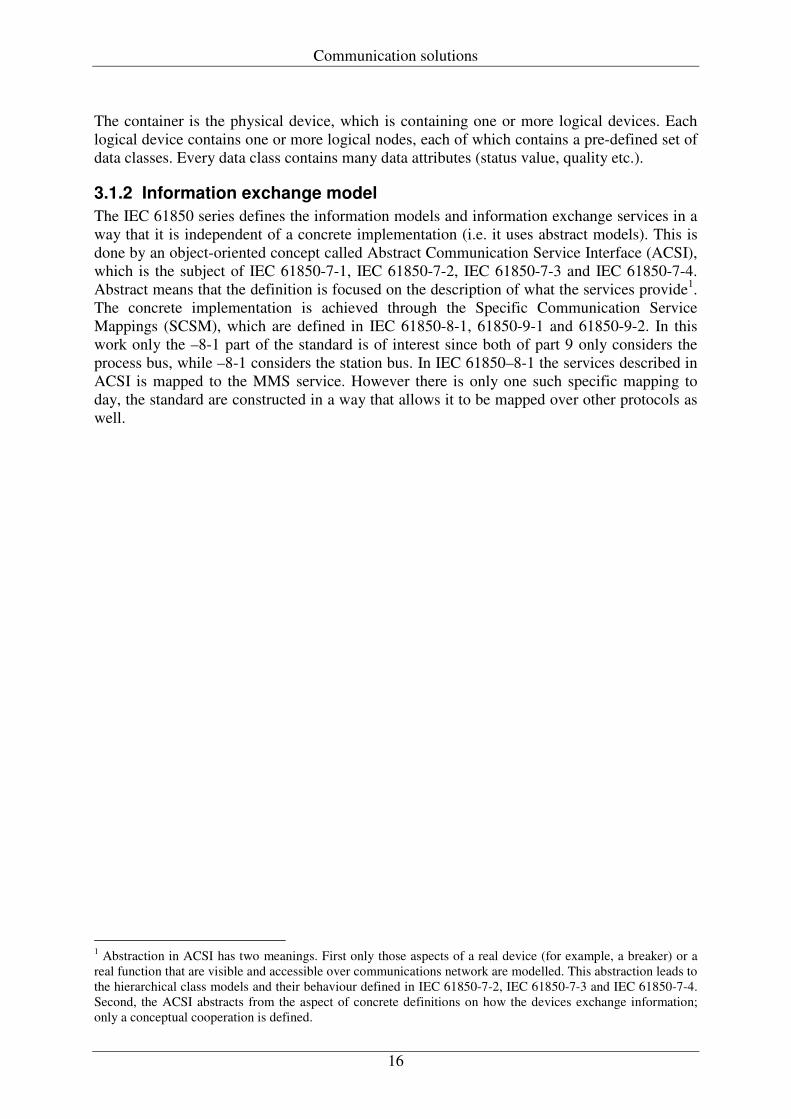
3.1.2 Information exchange model The IEC 61850 series defines the information models and information exchange services in a way that it is independent of a concrete implementation (i.e. it uses abstract models). This is done by an object-oriented concept called Abstract Communication Service Interface (ACSI), which is the subject of IEC 61850-7-1, IEC 61850-7-2, IEC 61850-7-3 and IEC 61850-7-4. Abstract means that the definition is focused on the description of what the services provide1. The concrete implementation is achieved through the Specific Communication Service Mappings (SCSM), which are defined in IEC 61850-8-1, 61850-9-1 and 61850-9-2. In this work only the –8-1 part of the standard is of interest since both of part 9 only considers the process bus, while –8-1 considers the station bus. In IEC 61850–8-1 the services described in ACSI is mapped to the MMS service. However there is only one such specific mapping to day, the standard are constructed in a way that allows it to be mapped over other protocols as well.
1 Abstraction in ACSI has two meanings. First only those aspects of a real device (for example, a breaker) or a real function that are visible and accessible over communications network are modelled. This abstraction leads to the hierarchical class models and their behaviour defined in IEC 61850-7-2, IEC 61850-7-3 and IEC 61850-7-4. Second, the ACSI abstracts from the aspect of concrete definitions on how the devices exchange information; only a conceptual cooperation is defined.
Communication solutions
17
Figure 6: Conceptual service model of the ACSI.
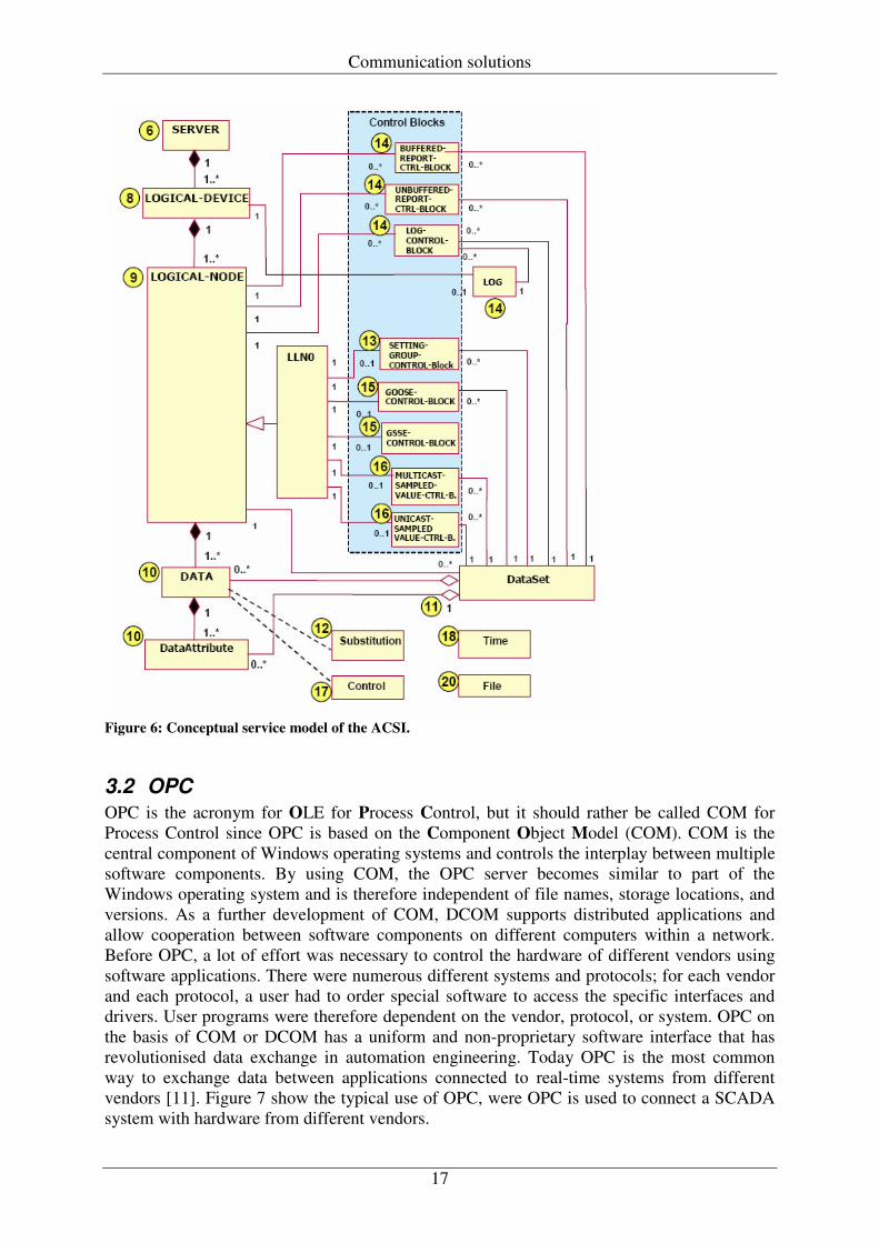
3.2 OPC OPC is the acronym for OLE for Process Control, but it should rather be called COM for Process Control since OPC is based on the Component Object Model (COM). COM is the central component of Windows operating systems and controls the interplay between multiple software components. By using COM, the OPC server becomes similar to part of the Windows operating system and is therefore independent of file names, storage locations, and versions. As a further development of COM, DCOM supports distributed applications and allow cooperation between software components on different computers within a network. Before OPC, a lot of effort was necessary to control the hardware of different vendors using software applications. There were numerous different systems and protocols; for each vendor and each protocol, a user had to order special software to access the specific interfaces and drivers. User programs were therefore dependent on the vendor, protocol, or system. OPC on the basis of COM or DCOM has a uniform and non-proprietary software interface that has revolutionised data exchange in automation engineering. Today OPC is the most common way to exchange data between applications connected to real-time systems from different vendors [11]. Figure 7 show the typical use of OPC, were OPC is used to connect a SCADA system with hardware from different vendors.
Communication solutions
18
Figure 7: OPC interface
3.3 MMS MMS (Manufacturing Message Specification) is an internationally standardised messaging system for exchanging real-time data and supervisory control information between networked devices and/or computer applications in a manner that is independent of the application function being performed or the developer of the device or application. MMS is an international standard (ISO 9506) that is developed and maintained by Technical Committee Number 184 (TC184), Industrial Automation, of the International Organization for Standardization (ISO). The messaging services provided by MMS are generic enough to be appropriate for a wide variety of devices, applications, and industries. For instance, the MMS Read service allows an application or device to read a variable from another application or device. Whether the device is a Programmable Logic Controller or a robot, the MMS services and messages are identical. Similarly, applications as diverse as material handling, fault annunciation, energy management, electrical power distribution control, inventory control, and deep space antenna positioning in industries as varied as automotive, aerospace, petro-chemical, electric utility, office machinery and space exploration have put MMS to useful work. MMS provides a comprehensive and flexible framework for exchanging variable information over a network. The MMS variable access model includes capabilities for named, unnamed (addressed), and named lists of variables. MMS also allows the type description of the variables to be manipulated as a separate MMS object (named type object). MMS variables can be simple (e.g. integer, boolean, floating point, string, etc.) or complex (e.g. arrays and structures). The services available to access and manage MMS variable and type objects are very powerful and include services for:
• Read and Write services allow MMS client applications to access the contents of Named Variables, Unnamed Variables, and Named Variable List objects.
Communication solutions
19
• The Information Report service allows a server to report the contents of a variable to a remote client in an unsolicited manner.
• Define, delete, and get attribute services are available for both variables and types to
allow clients to manage the variable access environment. Service options allow groups of variables to be accessed in a single MMS request, allow large arrays and complex structures to be partially accessed (alternate access), and allow clients to recast variable types and complex structures to suit their needs (access by description) [5].
20
4 Product information This chapter will present a description of the products considered in the solution to the research problem. The description will consist of hardware, software, development environments and communication capabilities. Also software implementations of IEC 61850 and communication software needed to present a solution are described here.
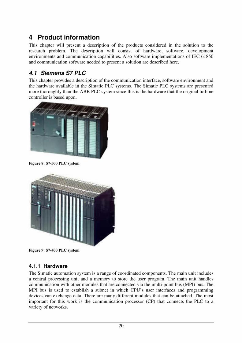
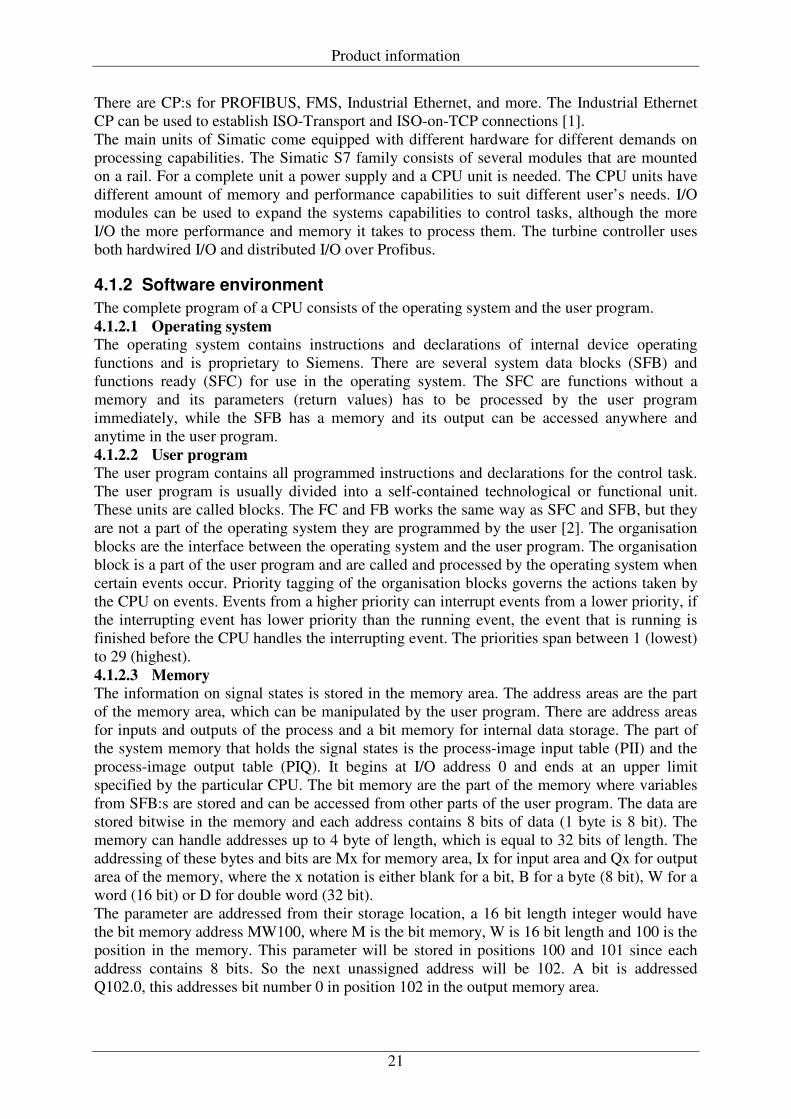
4.1 Siemens S7 PLC This chapter provides a description of the communication interface, software environment and the hardware available in the Simatic PLC systems. The Simatic PLC systems are presented more thoroughly than the ABB PLC system since this is the hardware that the original turbine controller is based upon.
Figure 8: S7-300 PLC system
Figure 9: S7-400 PLC system
4.1.1 Hardware The Simatic automation system is a range of coordinated components. The main unit includes a central processing unit and a memory to store the user program. The main unit handles communication with other modules that are connected via the multi-point bus (MPI) bus. The MPI bus is used to establish a subnet in which CPU’s user interfaces and programming devices can exchange data. There are many different modules that can be attached. The most important for this work is the communication processor (CP) that connects the PLC to a variety of networks.
Product information
21
There are CP:s for PROFIBUS, FMS, Industrial Ethernet, and more. The Industrial Ethernet CP can be used to establish ISO-Transport and ISO-on-TCP connections [1]. The main units of Simatic come equipped with different hardware for different demands on processing capabilities. The Simatic S7 family consists of several modules that are mounted on a rail. For a complete unit a power supply and a CPU unit is needed. The CPU units have different amount of memory and performance capabilities to suit different user’s needs. I/O modules can be used to expand the systems capabilities to control tasks, although the more I/O the more performance and memory it takes to process them. The turbine controller uses both hardwired I/O and distributed I/O over Profibus.
4.1.2 Software environment The complete program of a CPU consists of the operating system and the user program. 4.1.2.1 Operating system The operating system contains instructions and declarations of internal device operating functions and is proprietary to Siemens. There are several system data blocks (SFB) and functions ready (SFC) for use in the operating system. The SFC are functions without a memory and its parameters (return values) has to be processed by the user program immediately, while the SFB has a memory and its output can be accessed anywhere and anytime in the user program. 4.1.2.2 User program The user program contains all programmed instructions and declarations for the control task. The user program is usually divided into a self-contained technological or functional unit. These units are called blocks. The FC and FB works the same way as SFC and SFB, but they are not a part of the operating system they are programmed by the user [2]. The organisation blocks are the interface between the operating system and the user program. The organisation block is a part of the user program and are called and processed by the operating system when certain events occur. Priority tagging of the organisation blocks governs the actions taken by the CPU on events. Events from a higher priority can interrupt events from a lower priority, if the interrupting event has lower priority than the running event, the event that is running is finished before the CPU handles the interrupting event. The priorities span between 1 (lowest) to 29 (highest). 4.1.2.3 Memory The information on signal states is stored in the memory area. The address areas are the part of the memory area, which can be manipulated by the user program. There are address areas for inputs and outputs of the process and a bit memory for internal data storage. The part of the system memory that holds the signal states is the process-image input table (PII) and the process-image output table (PIQ). It begins at I/O address 0 and ends at an upper limit specified by the particular CPU. The bit memory are the part of the memory where variables from SFB:s are stored and can be accessed from other parts of the user program. The data are stored bitwise in the memory and each address contains 8 bits of data (1 byte is 8 bit). The memory can handle addresses up to 4 byte of length, which is equal to 32 bits of length. The addressing of these bytes and bits are Mx for memory area, Ix for input area and Qx for output area of the memory, where the x notation is either blank for a bit, B for a byte (8 bit), W for a word (16 bit) or D for double word (32 bit). The parameter are addressed from their storage location, a 16 bit length integer would have the bit memory address MW100, where M is the bit memory, W is 16 bit length and 100 is the position in the memory. This parameter will be stored in positions 100 and 101 since each address contains 8 bits. So the next unassigned address will be 102. A bit is addressed Q102.0, this addresses bit number 0 in position 102 in the output memory area.
Product information
22
4.1.2.4 Operation When the CPU starts a start-up program is executed, thereafter the signal states of PIQ are transferred to the output modules and the signal states of the input modules are transferred to the PII by the operating system. Then the main program runs. This is located in organisation block 1 (OB1). The operating system calls OB1 that has priority 1 (lowest) and can be interrupted by all events. The user program in OB1 then calls other blocks (i.e. user programs), which are processed in an order. When OB1 is completed, the operating system sets the signal states from PIQ to the output modules and reads new signal states from the input modules to PII. Finally when the program is completed, OB1 is executed again by the operating system.
4.1.3 Communication interface Communication processors are used to relieve the CPU of communication tasks. The communication utility specifies how the communication stations are to exchange data and how these data are to be treated. The utility is based on a protocol, which describes the coordination procedure between communication partners. Recognised utilities are S7 functions, Profibus, ISO-transport, ISO-on-TCP and some serial link protocols. The communication functions are the user program’s interface to the communication utility. The communication functions are integrated in the CPU’s operating system and are called by system blocks for internal Simatic S7 communication. Loadable blocks are available for communication with external devices thorough communication processors. Every CPU is equipped with the MPI bus on which Siemens own protocol is used. Transmission speed is up to 187.5 kbit/s and uses shielded two-wire copper cable or fiber optic cable, the physical connector is the same as for Profibus. The Profibus interface can transfer data up to 12 Mbit/s over either a shielded two-wire copper cable or a fiber optic conductor. Up to 127 stations can be connected and the communication is established using token ring technology where a master communicates with the slaves when it has the token. Data can be transferred using Profibus FMS and Profibus FDL and Profibus DP, also S7 functions can be used. Industrial Ethernet is the subnet for connection to computers. The connection uses a double-shielded coaxial cable or an industrial twisted pair. Also fiber optic cable is available. The communication interfaces are S7 functions, ISO-transport and ISO-on-TCP. Transmission speed is up to 100 Mbit/s.
4.1.4 Programming Step 7 is the software used for configuring and programming Simatic PLC, this means:
• Setting up managing projects • Configuring and assigning parameters to hardware and communications • Managing symbols • Creating programs for S7 programmable controller • Downloading programs to programmable controllers • Testing the automation system • Diagnosing plant failures
Step 7 conforms to the programming languages defined in IEC 61131-3, which is a standard for logic programming of controllers and the programming methods will not be explained here. The most common languages defined in IEC 61131-3 are:
• Ladder logic (LAD) is a graphical representation of the programming language. The syntax for the instructions is similar to a relay ladder logic diagram
Product information
23
• Statement list (ST) is a textual representation of the programming language, similar to machine code.
• Structured control language (SCL) is a Pascal-like programming language, which is more suitable for creating complex functions.
The turbine controller is implemented in FC’s and FB’s in the IEC 61131-3 languages and the process data is exchanged over Profibus using integers.
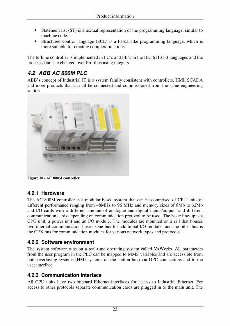
4.2 ABB AC 800M PLC ABB’s concept of Industrial IT is a system family consistent with controllers, HMI, SCADA and more products that can all be connected and commissioned from the same engineering station.
Figure 10 - AC 800M controller
4.2.1 Hardware The AC 800M controller is a modular based system that can be comprised of CPU units of different performance ranging from 48MHz to 96 MHz and memory sizes of 8Mb to 32Mb and I/O cards with a different amount of analogue and digital inputs/outputs and different communication cards depending on communication protocol to be used. The basic line-up is a CPU unit, a power unit and an I/O module. The modules are mounted on a rail that houses two internal communication buses. One bus for additional I/O modules and the other bus is the CEX bus for communication modules for various network types and protocols.
4.2.2 Software environment The system software runs on a real-time operating system called VxWorks. All parameters from the user program in the PLC can be mapped to MMS variables and are accessible from both overlaying systems (HMI systems on the station bus) via OPC connections and to the user interface.
4.2.3 Communication interface All CPU units have two onboard Ethernet-interfaces for access to Industrial Ethernet. For access to other protocols separate communication cards are plugged in to the main unit. The
Product information
24
800M system uses MMS for communication between the connected devices over an Ethernet interface.
4.2.4 Programming ABB’s Industrial IT suite conforms to the programming languages of IEC 61131-3. Also ABB’s own control module language is available. This programming method allows the user to mix all elements of IEC 61131-3 into pre-defined algorithms, to hide the control logic. By storing these control modules in a system library the solutions can be reused throughout the entire automation system. The control builder is tool used to specify a project containing all hardware components in a automation system, this is also where the user programs are written and compiled before they are transferred to the PLC.
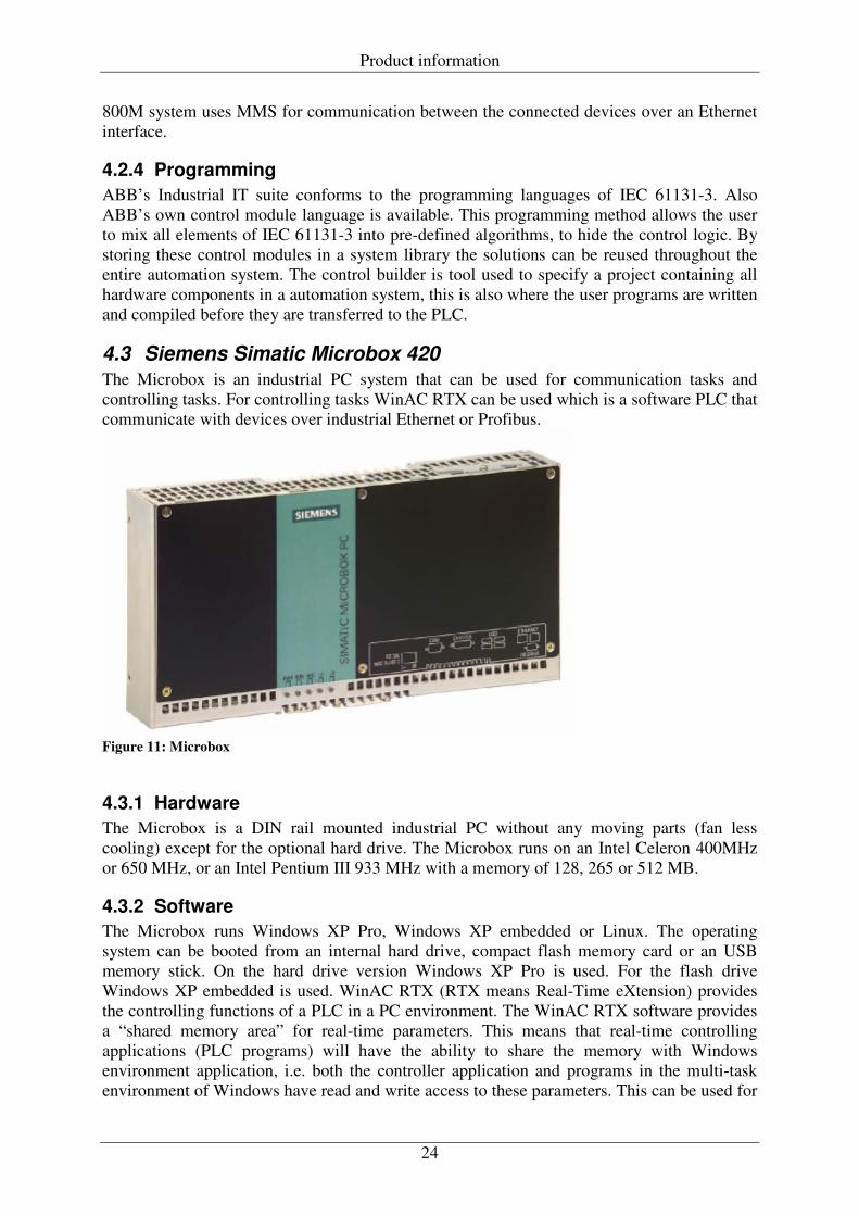
4.3 Siemens Simatic Microbox 420 The Microbox is an industrial PC system that can be used for communication tasks and controlling tasks. For controlling tasks WinAC RTX can be used which is a software PLC that communicate with devices over industrial Ethernet or Profibus.
Figure 11: Microbox
4.3.1 Hardware The Microbox is a DIN rail mounted industrial PC without any moving parts (fan less cooling) except for the optional hard drive. The Microbox runs on an Intel Celeron 400MHz or 650 MHz, or an Intel Pentium III 933 MHz with a memory of 128, 265 or 512 MB.
4.3.2 Software The Microbox runs Windows XP Pro, Windows XP embedded or Linux. The operating system can be booted from an internal hard drive, compact flash memory card or an USB memory stick. On the hard drive version Windows XP Pro is used. For the flash drive Windows XP embedded is used. WinAC RTX (RTX means Real-Time eXtension) provides the controlling functions of a PLC in a PC environment. The WinAC RTX software provides a “shared memory area” for real-time parameters. This means that real-time controlling applications (PLC programs) will have the ability to share the memory with Windows environment application, i.e. both the controller application and programs in the multi-task environment of Windows have read and write access to these parameters. This can be used for
Product information
25
third-party Windows applications that need to send/receive real-time information to control systems, such as set-point values or calculated values from the control application.
4.3.3 Communication interface For user communication the Microbox has 1 serial port (9-pin COM port), 4 USB 2.0 connectors and DVI-I monitor interface. For network communication the Microbox are equipped with 2 Ethernet ports and one Profibus/MPI connector. An important difference between a Microbox and a PLC regarding the controlling purposes is that a Microbox does not provides analogue or digital inputs or outputs the same way as a PLC. The only way to communicate with field devices is by the use of field busses, either by Ethernet or Profibus/MPI.
4.4 Tamarack software stack for embedded systems Tamarack Consulting has developed a Software stack for embedded devices for use in integration of IEC 61850 in different products. The software is an application programming interface (API) delivered in ANSI C code. All IEC 61850 services accesses the user data strictly through data handler functions, which translates from the local data representation to the IEC 61850 data encoding. Data handlers that are included in the software are restricted to variables defined in RAM in C, but customised handlers for any access method can be developed. The protocol stack does not include a TCP/IP stack so the software needs access to a system sockets interface. A server application is generated in C source code using the included proprietary object builder. The data objects can either be defined static (i.e. at compile time) or dynamically using SCL-files as defined in IEC 61850-6.
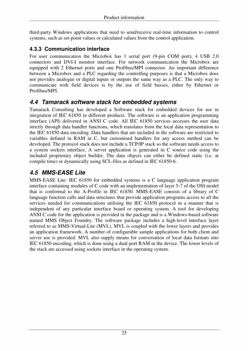
4.5 MMS-EASE Lite MMS-EASE Lite: IEC 61850 for embedded systems is a C language application program interface containing modules of C code with an implementation of layer 5-7 of the OSI model that is conformal to the A-Profile in IEC 61850. MMS-EASE consists of a library of C language function calls and data structures that provide application programs access to all the services needed for communications utilising the IEC 61850 protocol in a manner that is independent of any particular interface board or operating system. A tool for developing ANSI C code for the application is provided in the package and is a Windows-based software named MMS Object Foundry. The software package includes a high-level interface layer referred to as MMS-Virtual-Lite (MVL). MVL is coupled with the lower layers and provides an application framework. A number of configurable sample applications for both client and server use is provided. MVL also supply means for conversation of local data formats into IEC 61850 encoding, which is done using a dual-port RAM in the device. The lower levels of the stack are accessed using sockets interface in the operating system.
Product information
26
Figure 12: Software package provided by Sisco
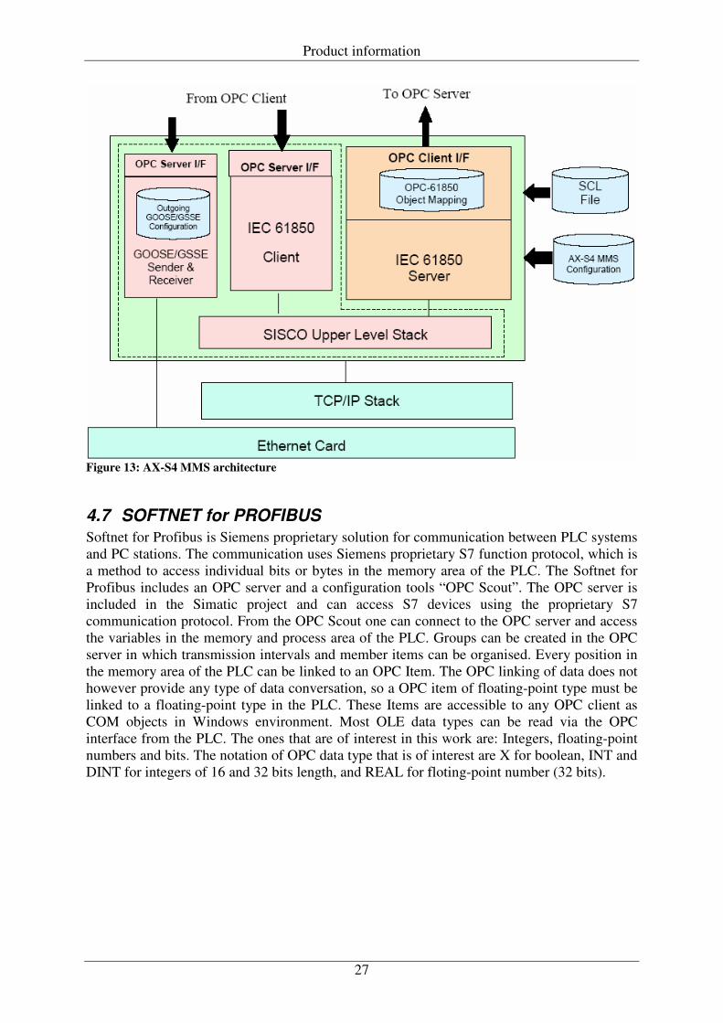
4.6 AX-S4 MMS AX-S4-MMS is an IEC 61850 interface for windows applications supporting OPC data access (DA) interface and Dynamic Data Exchange (DDE). It features implementations of server/client functionality. The principle is to use a PC platform running Windows 2000/XP for the IEC 61850 server and access process parameters as OPC items from arbitrary OPC server. The server functionality is implemented from the MMS-Ease Lite, and support write/read and reporting. The logical nodes and data objects in the server are configured via a SCL file that is imported to the server. There are options to set mapped items with read only or read/write permission. The scan rate i.e. how often the IEC 61850 server should update the values from the OPC server, is grouped and every individual value are associated with a group. The user creates groups to which permissions and scan rates are associated. This way the most important values can be updated as often as one would like, whilst the less frequently used values can be updated less often. During read requests the server responds with the initially set value or the latest value acquired by the OPC client. During write request the server writes the value to the OPC server before it sends acknowledgment to the IEC 61850 client. Figure 13 shows the architecture diagram of AX-S4 MMS. The software also includes an OPC server and an IEC 61850 client that can be configured for accessing IEC 61850 devices from Windows applications.
Product information
27
Figure 13: AX-S4 MMS architecture
4.7 SOFTNET for PROFIBUS Softnet for Profibus is Siemens proprietary solution for communication between PLC systems and PC stations. The communication uses Siemens proprietary S7 function protocol, which is a method to access individual bits or bytes in the memory area of the PLC. The Softnet for Profibus includes an OPC server and a configuration tools “OPC Scout”. The OPC server is included in the Simatic project and can access S7 devices using the proprietary S7 communication protocol. From the OPC Scout one can connect to the OPC server and access the variables in the memory and process area of the PLC. Groups can be created in the OPC server in which transmission intervals and member items can be organised. Every position in the memory area of the PLC can be linked to an OPC Item. The OPC linking of data does not however provide any type of data conversation, so a OPC item of floating-point type must be linked to a floating-point type in the PLC. These Items are accessible to any OPC client as COM objects in Windows environment. Most OLE data types can be read via the OPC interface from the PLC. The ones that are of interest in this work are: Integers, floating-point numbers and bits. The notation of OPC data type that is of interest are X for boolean, INT and DINT for integers of 16 and 32 bits length, and REAL for floting-point number (32 bits).
28
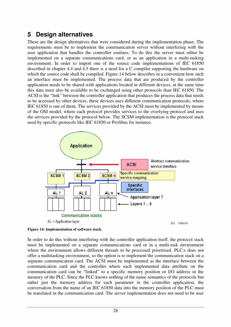
5 Design alternatives These are the design alternatives that were considered during the implementation phase. The requirements must be to implement the communication server without interfering with the user application that handles the controller routines. To do this the server must either be implemented on a separate communications card, or as an application in a multi-tasking environment. In order to import one of the source code implementations of IEC 61850 described in chapter 4.4 and 4.5 there is a need for a C compiler supporting the hardware on which the source code shall be compiled. Figure 14 below describes in a convenient how such an interface must be implemented. The process data that are produced by the controller application needs to be shared with applications located in different devices, at the same time this data must also be available to be exchanged using other protocols than IEC 61850. The ACSI is the “link” between the controller application that produces the process data that needs to be accessed by other devices, these devices uses different communication protocols, where IEC 61850 is one of them. The services provided by the ACSI must be implemented by means of the OSI model, where each protocol provides services to the overlying protocol and uses the services provided by the protocol below. The SCSM implementation is the protocol stack used by specific protocols like IEC 61850 or Profibus for instance.
Figure 14: Implementation of software stack. In order to do this without interfering with the controller application itself, the protocol stack must be implemented on a separate communications card or in a multi-task environment where the environment allows different threads to be processed prioritised. PLC:s does not offer a multitasking environment, so the option is to implement the communication stack on a separate communication card. The ACSI must be implemented as the interface between the communication card and the controller where each implemented data attribute on the communication card can be “linked” to a specific memory position or I/O address in the memory of the PLC. Since the PLC knows nothing of the name semantics of the protocols but rather just the memory address for each parameter in the controller application, the conversation from the name of an IEC 61850 data into the memory position of the PLC must be translated in the communication card. The server implementation does not need to be user
Design alternatives
29
configurable since a turbine controller only will have a certain function and that function will not change over time. This means that the translation between IEC 61850 data attributes and PLC parameters into the memory position where the value of each PLC parameter is stored can be configured before compilation of the server. So if a server is possible to implement on a PLC system, all of the logical nodes and data objects can be defined from the start. The design alternatives that support an implementation like this are presented below.
5.1 Implementation on ABB PLC system: ABB are currently running a project to implement IEC 61850 into their automation system. How this will be implemented is not decided by ABB yet, but it will be implemented on a separate communication card using one of the two source code implementation of IEC 61850 described in chapter 4.4 and 4.5. The interface between the controller and IEC 61850 is the mapping of data objects in IEC 61850 to the process values stored in the memory of the controller.
5.1.1 Design alternative for AC 800M The communication card ABB are developing does not fit the requirements for Vattenfall, since ABB not will implement the complete functionality of IEC 61850. The development environment for ABB’s communications card is the Tornado by Windriver Inc (which supports C), this opens a opportunity for Vattenfall to implement and test the functionality of a IEC 61850 server that are required by the turbine controller without dependence from ABB’s development project. For further development of this communication card into a complete product, Vattenfall could either contract ABB using their customer funded research program or by in-house development. The requirements for this would be: Hardware:
• ABB AC800M PLC system • SM810 Communication module
Software: • Software package with communication stack and server application.
o SISCO o Tamarack
• TCP/IP stack for the communication card • ABB development environment / Tornado development environment from Windriver
Inc. • ABB control builder
The software package would be implemented on a separate communication card containing the TCP/IP stack. The software package containing the realisation of the ACSI with it’s logical nodes and data attributes and would be linked to the parameters in the user program of the controller. The encoding to IEC 61850 data format is provided by the server application that is provided by the software package. Uncertainties: No support from ABB regarding the development environment is avaliable. How to define the mapping of the data objects in the logical node to the user parameters in the PLC, since the parameters needs to be accessible for both read and write for both the user application and the server.
Design alternatives
30
Expected results: A successful result would prove the AC 800M as a possible turbine controller including an IEC 61850 interface for future installations of turbine controllers. For the modern turbine controller this type of implementation could be used as a gateway by connecting the AC800M to the S7-300 PLC using Profibus or Ethernet and configure the controller application in the AC800M to cyclically read all process values from the S7-300 system. This way the turbine controller application in the S7-300 is unaltered and the AC800M will be the IEC 61850 communication interface for the turbine controller.
5.2 Implementation on Siemens PLC system: Siemens has no plans for developing a communication processor for the Simatic series of PLC with support for the IEC 61850 protocol. There seems to be no possibilities to use or license Siemens development environment for in-house development of a communication card for Vattenfall. Because of this there are no alternatives of importing any of the software’s described in chapter 4 to the PLC.
5.2.1 Design alternative for Simatic PLC According to Siemens Automation and Drives it should be possible to implement the communication stack defined in IEC 61850 in Step 7 using the IEC 61131-3 language. However this not supported by Siemens Automation and Drives. The Simatic S7-300 that is currently used, as turbine controller does not have enough performance to support a new communication protocol and the control application. Siemens automation and drives recommended that for such an implementation the S7-400 system should be used or to implement the server application on a separate S7-300 controller and link them both using MPI bus. In order to implement the communication stack on a S7-400 the CP 431-1 would be a suitable communication card to use, since it provides an implementation of layer 1-4 that is defined as TCP/IP T-profile in IEC 61850-8-1. Siemens Industrial Solutions (independent from Automation and Drives) has developed a client for communication with protection devices. Since the protocol stack for a server and a client are the same and only the application it self (client application or server application) are different this might be a feasible option to develop an IEC 61850 server for the Simatic PLC. Siemens Industrial Solutions implemented this client using the IEC 61131-3 language and the client function block runs on a S7-400 and it uses the communication utilities of the CP 431-1 communication card. Layer 5-7 which is described as the A-Profile in IEC 61850 must be implemented as a function block in a S7-400 system.
5.3 PC Gateway design Since implementation of IEC 61850 on a separate communications card requires that Vattenfall have access to the development environment of the specific vendor, a PC gateway design is more suitable if Vattenfall would like to develop an interface for IEC 61850. The interface would consist of standard off the shelf products and would be user configurable without having to be dependent of vendor supplied development environments.
5.3.1 Microbox gateway and WinAC RTX The multi-task environment of Windows and the shared memory area of WinAC RTX can be used to implement one of the source code implementations of IEC 61850 in a convenient way. Since the Microbox are not equipped with digital and analogue input and outputs either the turbine controller would need to be implemented in the soft PLC environment or that a
Design alternatives
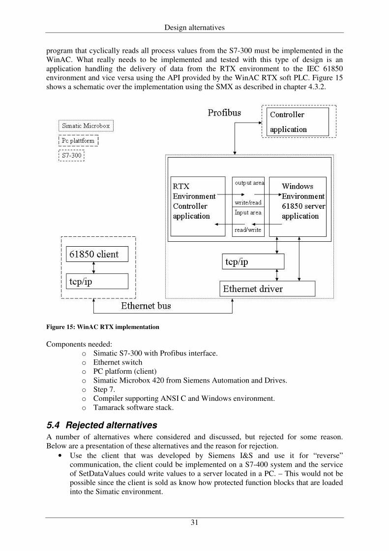
31
program that cyclically reads all process values from the S7-300 must be implemented in the WinAC. What really needs to be implemented and tested with this type of design is an application handling the delivery of data from the RTX environment to the IEC 61850 environment and vice versa using the API provided by the WinAC RTX soft PLC. Figure 15 shows a schematic over the implementation using the SMX as described in chapter 4.3.2.
Figure 15: WinAC RTX implementation Components needed:
o Simatic S7-300 with Profibus interface. o Ethernet switch o PC platform (client) o Simatic Microbox 420 from Siemens Automation and Drives. o Step 7. o Compiler supporting ANSI C and Windows environment. o Tamarack software stack.
5.4 Rejected alternatives A number of alternatives where considered and discussed, but rejected for some reason. Below are a presentation of these alternatives and the reason for rejection.
• Use the client that was developed by Siemens I&S and use it for “reverse” communication, the client could be implemented on a S7-400 system and the service of SetDataValues could write values to a server located in a PC. – This would not be possible since the client is sold as know how protected function blocks that are loaded into the Simatic environment.
Design alternatives
32
• Implementation on ABB PLC system. – If Vattenfall were to implement the interface on ABB PLC systems, the development environment from Windriver would need to be licensed and the source code implementation of IEC 61850 needs to be licensed. This would mean a very big development project, and is not suitable for testing during a master thesis work.
• Order development from ABB. – Vattenfall would be too dependent on a vendor in order to make changes to the interface.
• Implementation on Simatic PLC system using IEC 61131-3. This would take too much resource and would be a very costly alternative, and it is not certain to be fully functional.
• Implementation on Microbox using WinAC RTX and Tamarack software implementation. – This would be a fully flexible and user configurable solution. However this alternative is very costly since it includes rewriting the functions of the turbine controller and includes very expensive software implementations of IEC 61850. This also would mean that Vattenfall would need to start a large development project.
33
6 Design proposal This is the design alternative that has been selected for a test, the design has been discussed with the vendors of the products included in the design, and they offer support for the implementation. This is the best alternative for a design that shall be possible to test during this project and it does fulfil the requirements for an interface.
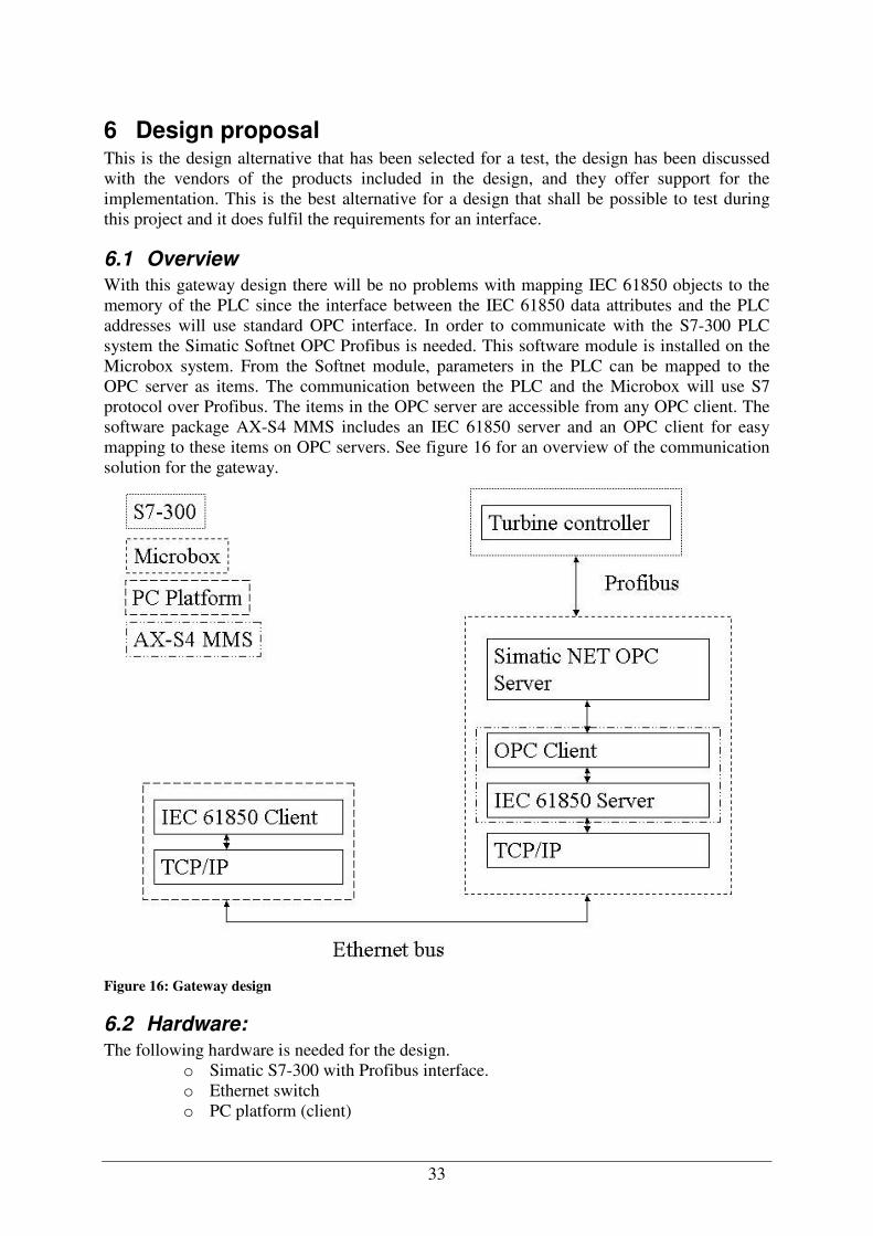
6.1 Overview With this gateway design there will be no problems with mapping IEC 61850 objects to the memory of the PLC since the interface between the IEC 61850 data attributes and the PLC addresses will use standard OPC interface. In order to communicate with the S7-300 PLC system the Simatic Softnet OPC Profibus is needed. This software module is installed on the Microbox system. From the Softnet module, parameters in the PLC can be mapped to the OPC server as items. The communication between the PLC and the Microbox will use S7 protocol over Profibus. The items in the OPC server are accessible from any OPC client. The software package AX-S4 MMS includes an IEC 61850 server and an OPC client for easy mapping to these items on OPC servers. See figure 16 for an overview of the communication solution for the gateway.
Figure 16: Gateway design
6.2 Hardware: The following hardware is needed for the design.
o Simatic S7-300 with Profibus interface. o Ethernet switch o PC platform (client)
Design proposal
34
o Simatic Microbox 420 from Siemens Automation and Drives. o Monitor o Keyboard o Mouse
6.3 Software The following software is needed for the design.
o Step 7. o SOFTNET for PROFIBUS. o AX-S4 MMS from Sisco Inc. o Tamarack MMSd test client.
6.4 Design specifications This chapter will present the specification on what that will be implemented in the server, for a architecture diagram of AX-S4 MMS, see figure 13.
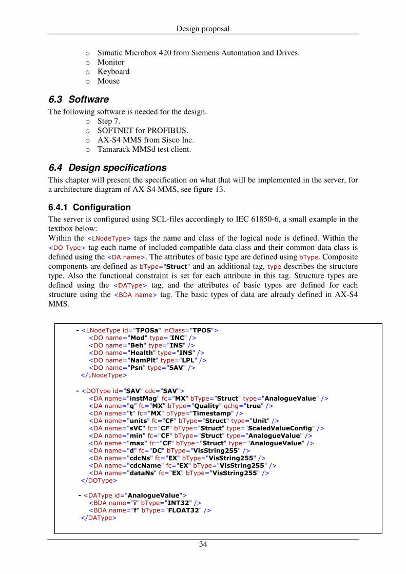
6.4.1 Configuration The server is configured using SCL-files accordingly to IEC 61850-6, a small example in the textbox below: Within the ��������� tags the name and class of the logical node is defined. Within the ��� ��� tag each name of included compatible data class and their common data class is defined using the ��� ����. The attributes of basic type are defined using ����� Composite components are defined as ������������� and an additional tag, ��� describes the structure type. Also the functional constraint is set for each attribute in this tag. Structure types are defined using the ������ tag, and the attributes of basic types are defined for each structure using the ���� ���� tag. The basic types of data are already defined in AX-S4 MMS.
� ��������� �������� ������������� � ��� ������� �� ��������� �
� ��� ���������� ��������� � � ��� ������������ ��������� � � ��� ������������ ��������� � � ��� ���������� ��������� �
� ����������
� ������ �������� ��������� � ��� ������������� ������� ������������� �������� �������� � � ��� ������ � ������� ������!����"� �� !������� � � ��� �������� ������� �������������#� � � ��� ������������ �����$� ������������� �����%���� � � ��� ���������� �����$� ������������� ��������������� �&��� � � ��� ���������� �����$� ������������� �������� �������� �
� ��� �������'� �����$� ������������� �������� �������� � � ��� �������� ����(�� ���������������)**� � � ��� ������������ ����+�� ���������������)**� � � ��� ������������� ����+�� ���������������)**� � � ��� ����������� ����+�� ���������������)**� �
� �������
�� ������ ������� �������� � ���� �������� ���������,)� � � ���� ������&� ������$���,)� �
� �������
Design proposal
35
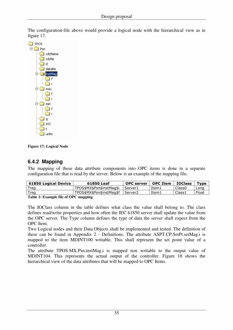
The configuration-file above would provide a logical node with the hierarchical view as in figure 17.
Figure 17: Logical Node
6.4.2 Mapping The mapping of these data attribute components into OPC items is done in a separate configuration file that is read by the server. Below is an example of the mapping file. -./*0�� �����(�1���� -./*0���&� ������1��� �������� ������ �"#��
�"�! �#�$%&'%#��%����&�!%� $�"(�") *���) �����+ ���!
�"�! �#�$%&'%#��%����&�!%� $�"(�", *���) �����) -����
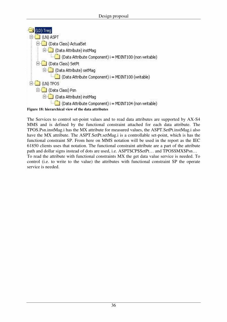
Table 1: Example file of OPC mapping The IOClass column in the table defines what class the value shall belong to. The class defines read/write properties and how often the IEC 61850 server shall update the value from the OPC server. The Type column defines the type of data the server shall expect from the OPC Item. Two Logical nodes and their Data Objects shall be implemented and tested. The definition of these can be found in Appendix 2 - Definitions. The attribute ASPT.CP.SetPt.setMag.i is mapped to the item MDINT100 writable. This shall represent the set point value of a controller. The attribute TPOS.MX.Psn.instMag.i is mapped non writable to the output value of MDINT104. This represents the actual output of the controller. Figure 18 shows the hierarchical view of the data attributes that will be mapped to OPC Items.
Design proposal
36
Figure 18: hierarchical view of the data attributes The Services to control set-point values and to read data attributes are supported by AX-S4 MMS and is defined by the functional constraint attached for each data attribute. The TPOS.Psn.instMag.i has the MX attribute for measured values, the ASPT.SetPt.instMag.i also have the MX attribute. The ASPT.SetPt.setMag.i is a controllable set-point, which is has the functional constraint SP. From here on MMS notation will be used in the report as the IEC 61850 clients uses that notation. The functional constraint attribute are a part of the attribute path and dollar signs instead of dots are used, i.e. ASPT$CP$SetPt… and TPOS$MX$Psn… To read the attribute with functional constraints MX the get data value service is needed. To control (i.e. to write to the value) the attributes with functional constraint SP the operate service is needed.
37
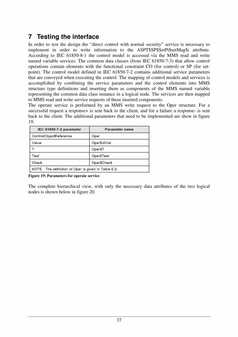
7 Testing the interface In order to test the design the “direct control with normal security” service is necessary to implement in order to write information to the ASPT$SP$SetPt$setMag$i attribute. According to IEC 61850-8-1 the control model is accessed via the MMS read and write named variable services. The common data classes (from IEC 61850-7-3) that allow control operations contain elements with the functional constraint CO (for control) or SP (for set-point). The control model defined in IEC 61850-7-2 contains additional service parameters that are conveyed when executing the control. The mapping of control models and services is accomplished by combining the service parameters and the control elements into MMS structure type definitions and inserting them as components of the MMS named variable representing the common data class instance in a logical node. The services are then mapped to MMS read and write service requests of these inserted components. The operate service is performed by an MMS write request to the Oper structure. For a successful request a response+ is sent back to the client, and for a failure a response- is sent back to the client. The additional parameters that need to be implemented are show in figure 19.
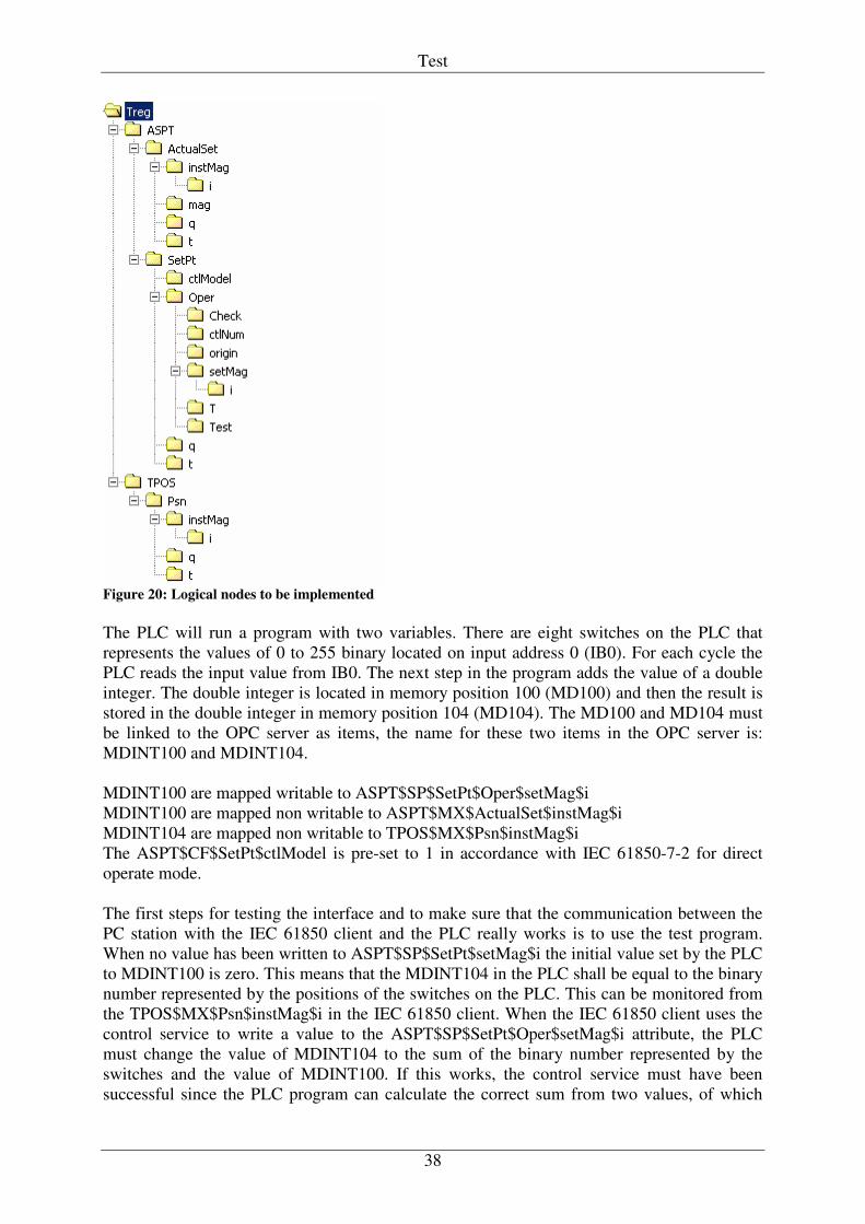
Figure 19: Parameters for operate service The complete hierarchical view, with only the necessary data attributes of the two logical nodes is shown below in figure 20.
Test
38
Figure 20: Logical nodes to be implemented The PLC will run a program with two variables. There are eight switches on the PLC that represents the values of 0 to 255 binary located on input address 0 (IB0). For each cycle the PLC reads the input value from IB0. The next step in the program adds the value of a double integer. The double integer is located in memory position 100 (MD100) and then the result is stored in the double integer in memory position 104 (MD104). The MD100 and MD104 must be linked to the OPC server as items, the name for these two items in the OPC server is: MDINT100 and MDINT104. MDINT100 are mapped writable to ASPT$SP$SetPt$Oper$setMag$i MDINT100 are mapped non writable to ASPT$MX$ActualSet$instMag$i MDINT104 are mapped non writable to TPOS$MX$Psn$instMag$i The ASPT$CF$SetPt$ctlModel is pre-set to 1 in accordance with IEC 61850-7-2 for direct operate mode. The first steps for testing the interface and to make sure that the communication between the PC station with the IEC 61850 client and the PLC really works is to use the test program. When no value has been written to ASPT$SP$SetPt$setMag$i the initial value set by the PLC to MDINT100 is zero. This means that the MDINT104 in the PLC shall be equal to the binary number represented by the positions of the switches on the PLC. This can be monitored from the TPOS$MX$Psn$instMag$i in the IEC 61850 client. When the IEC 61850 client uses the control service to write a value to the ASPT$SP$SetPt$Oper$setMag$i attribute, the PLC must change the value of MDINT104 to the sum of the binary number represented by the switches and the value of MDINT100. If this works, the control service must have been successful since the PLC program can calculate the correct sum from two values, of which

Test
39
one was written to the PLC over an Ethernet bus using IEC 61850 as communication protocol. In order to test the functionality from the IEC 61850 server two types of clients is used. The first client is MMS Object Explorer, this client is bundled with the AX-S4 MMS suite and the license agreement does not allow installation on more that one computer, this means that it can be used on the Microbox where the server are located, i.e. the object explorer is used for testing locally without any network traffic. The second client is the MMSd Test Client, which is an MMS test client from Tamarack Consulting. This client is used from the client computer and connects to the Microbox over an Ethernet bus (see figure 16). Below there are a screenshot from the MMSd test clients showing the data structures and their values when connected to the server. In the name column in figure 21 the second row named “Treg_testC1/ASPT1$SP$SetPt$Oper” shows the values for each parameter that are defined in the Oper structure.
Figure 21: Screenshot from MMSd Test Client The results are positive from the testing. Both of the clients can use the GetDataValues service on the two instMag attributes and the Operate service on the setMag attribute in accordance with the standard. This means that it possible to map data of 32 bit length integer (double integer) in the turbine controller into data objects in IEC 61850 of basic type int32.
40
8 Results The purpose of this master thesis work was to provide technological and economical feedback on implementation of an IEC 61850 interface for turbine controllers. The technological aspect of the goals where set to implement and test an interface for IEC 61850 and that has been completed. An operational server interface for turbine controller has been presented and tested. The testing of this interface has however only covered the GetDataValue and the Operate service. The goal from the project specification has been fulfilled as this report provides a summary of the products that are suitable to select in order to implement 61850 for turbine controller. The report does also contain design alternatives and results from the testing of one of the design alternatives. Economical factors for developing the design proposal into a complete and fully functional product are not easy to estimate. What the writer can point out is the costs for hardware and software that will come up if Vattenfall would decide to continue the development of this gateway design. The prices are presented separately to Vattenfall and not in this report.
41
9 Future work This chapter will present future work that needs to be done on the tested interface. It will also provide a discussion regarding future products that might be of interest to test.
9.1 Implemented interface One of the limitations of the server is that it cannot handle data conversation from local formats into IEC 61850 encoding. Presentation of the data from the turbine controller must therefore be in a format expected by the IEC 61850 server. Since the turbine controller does not use real floating-point numbers but rather integers that are re-calculated into floating point numbers. This is due to limitations over the Profibus and currently installed equipment, some routine for converting formats from the local format in the controller into the type that IEC 61850 use as basic types for each data attribute must be implemented in the controller. Or the problem with the equipment must be solved in order to use real floating-point numbers in the turbine controller. However it is important to point out that this design actually is an operational IEC 61850 interface for turbine controllers. This interface does not only cover the turbine controller but also any kind of controller that holds data that would be of interest to present for an IEC 61850 client. The limitations are of course the possibilities to find correct communications network for the OPC server. Siemens equipment uses the proprietary S7 communication over Profibus. It is also possible to use OPC over Ethernet to communicate with controllers. Since the Microbox has two Ethernet ports, one of them can act as a dedicated OPC bus, while the other communicates on the station bus. This would make it possible to communicate with ABB controller equipment as well as the GE Fanuc PLC systems using one of the Ethernet ports for OPC communication and the other Ethernet port for communication on the station bus. Further testing regarding services are required since this project only tested a few services. Other control services than Operate should be tested, today there are some limitations to the control services. Only “direct control with normal security” and “Select Before Operate (SBO) control with normal security” is implemented in AX-S4 MMS. The Operate service is supported for both direct and SBO control, but the “time activated operate” service is not supported. The optional report is not generated in either case. Performance of the server has not been tested in this work. This would be an interesting are for future work with the server. Also a test with a device that gets control values using an IEC 61850 client from the gateway is of interest. An important aspect regarding supported services and the functionality of the AX-S4 MMS IEC 61850 Server is that the version used and tested is only a beta version. The first official version might add functionality that is not there yet. Some “bugs” were found during the implementation that are worth mentioning for documentation. The server does not work if the system time in Windows is set east of GMT, this is a known bug from SISCO. Also the ASPT$SP$SetPt$t attribute, which is the time stamp attribute for ASPT$SP$SetPt$Oper$SetMag is not found and mapped by the server. This has to do with the algorithm that locates the time stamp attribute for controlled values.
42
9.2 Future products The ambition from the beginning of this work was to implement the interface directly in the PLC or in a separate communication processor. Due to restrictions from Siemens to access their development environment this was not possible. Therefore the PC based gateway design is the best choice. The work done by Siemens I&S to implement an IEC 61850 client based on Step 7, does however prove that it should be feasible to implement the communication stack used by IEC 61850 in a Simatic PLC. If this is economically or technologically beneficial instead of basing a future implementation in the PLC on the source code implementations of IEC 61850 is not answered by this report. During discussions of requirements with external experts, the general opinion was that it is not cost effective to implement this in a Simatic PLC using Step 7. It is even not for certain that it is technologically feasible to implement the server application in the Simatic environment using a high-level programming language like ST. This is something that needs to be further investigated. In order to get the interface directly into the controller the option is to migrate the turbine controller to the Microbox running a WinAC RTX environment and a communication application on the Windows environment (see chapter 5.3.1). This solution would utilise the Simatic S7-300 for communication with hard-wired I/O’s and the Microbox is running the controller application and the communication over the Ethernet bus. Today Siemens Automation and Drives have no interest in the development of an IEC 61850 server for PLC systems, since there is no market for this type of application. Siemens promotes the SICAM PAS system as their solution of IEC 61850 communications, but this computer only feature an IEC 61850 client for communication with distributed servers located in field devices. Options that include in-house development of the turbine controller with an integrated interface include changing vendor of automation equipment. Automation Direct offers a PLC line DL-205 with an optional CPU unit based on a 100Mhz processor and 8Mb of RAM, and communication with I/O’s using the backplane bus. The operating system of the WinCPU unit is Windows CE, which would be a suitable environment for Sisco or Tamarack software. Probably most of the controlling routines for the turbine controller would need to be reprogrammed to suit the new PLC. This however would be a controller with enough resources for controlling tasks and IEC 61850 communication tasks. The possibilities to use this controller with installations of treg 1.0 would be limited, as this PLC is not compatible with the I/O cards that are installed today. Also there would be a need for two developments lines, one gateway design for existing turbine controllers and one controller design for upcoming installations. Within the next years when the information model for hydro power plants are released the vendors will for sure be more interested in developing solutions for PLC systems by themselves. ALSTOM Power is currently running a master thesis work for investigating and testing an implementation of IEC 61850 using the Tamarack software into their soft logic PCX controllers. The result of this work is presented sometimes during April or May. When the results of that work are concluded ALSTOM Power will start the implementation of an IEC 61850 interface on the soft logic PCX controller. This controller could prove to be a very interesting for future turbine controllers and station/unit computers. As of today most vendors of PLC equipment that where contacted during the investigation phase didn’t seem to have a very big interest of developing products for IEC 61850 for PLC equipment. This is because there is no market today for substation automation using standard PLC automation equipment. ABB and VA-TECH have shown interest in developing their own IEC 61850 servers for their PLC automation equipment in the future. Both companies
Future products
43
seem to have interest in doing so. VA-TECH are a large supplier of hydro power plant automation and are members of the IEC group specifying the information model for hydro power plants have controllers that according to their own statement are suitable for an IEC 61850 implementation and they will implement this in their turbine controller that are delivered with their solution for hydro power plant automation. ABB are currently running a project for developing a communications module for AC 800M controller equipped with an IEC 61850 server for GOOSE messaging between substation protection devices and PLC automation products using the MMS EASE-Lite source code. This step was initiated by ABB after demands by their customers to integrate the PLC equipment with the controlling and protection devices for substations. It would be reasonable to assume that ABB would develop this product into a complete server for messaging on station bus if there are demands/interests from their customers. ABB also offers customer financed development of products. This would make it possible for Vattenfall to order a communication card for use with PLC systems. In the future there will be alternatives of controllers capable of communicating with IEC 61850 both for station bus and for process bus. If these are freely programmable like a PLC system and the user can link any parameter in the PLC:s memory register into any data object of IEC 61850 or if they will have a pre-defined set of functions that will produce the information defined in IEC 61850 is unknown and the vendors seems to yet not have taken the decision of how to implement these controllers.
44
10 References to external experts Fred Steinhauser, Product Manager, Omicron (Austria), European reseller of Tamarack Consulting products, [email protected]
Mr. Steinhauser has provided information regarding the software products from Tamarack Consulting.
Ralph Mackiewicz, Vice President SISCO (USA), [email protected]
Mr. Mackiewicz has provided information regarding software products from SISCO INC.
Samuel Wenz, Siemens I&S (Germany), [email protected]
Mr. Wenz has developed the client for communication between S7-400 PLC systems and Siprotec relays.
Kenneth Quinteros, Promotor, Siemens Automation and Drives (Sweden), [email protected]
Mr. Quinteros has provided information regarding Simatic products and OPC communication.
Urban Nygren, ABB (Sweden), [email protected]
Kenneth Fridholm, ABB (Sweden), [email protected]
Rolf Setthammar, ABB (Sweden), [email protected]
M.r Setthammar has provided information regarding ABB’s project with the development of a communication card for the AC 800M PLC system.
Anders Ramberg, Sales Engineer, Siemens (Sweden), [email protected]
Tony Knutsson, VA-TECH SAT (Denmark), [email protected]
Jenz Päutz, Marketing Manager SAT VA-TECH (Austria), [email protected]
Alfred Maschka, AMA-Systems (Germany), European reseller of SISCO and Direct Automation products.
Mr. Maschka has provided information regarding PLC products from Automation Direct, and information regarding the software products from SISCO.
Irmhild Maschka, President of AMA-systems (Germany), [email protected]
John Bruder, Development Engineer, SISCO (USA), [email protected]
Mr. Bruder has provided support for the implementation of AX-S4 MMS.
Denise Patrishkoff, Technical Service Coordinator, SISCO (USA), [email protected]
45
11 References for articles and manuals
[1] Hans Berger, Automating with Simatic, 2003, ISBN 3-89578-223-8 [2] Siemens, Communication with Simatic, 1997, ordering # 6ES7 398-8EA00-8BA0 [3] Siemens, NCM for Industrial Ethernet – Manual, 2003, ordering # C79000-G8976-
C129-07 [4] Cisco, Introduction to Internet,
http://www.cisco.com/univercd/cc/td/doc/cisintwk/ito_doc/introint.htm. 26/10-05 [5] Ralph Mackiewicz, An Overview to the Manufacturing Message Specification, 1994
http://www.baetzler.de/nwapps/mms.html 16/3-06 [6] ABB, Introduction and configuration, ABB Manual. Document # 3BSE035980R4101 [7] Simatic Webpage, www.siemens.com/simatic [8] ABB Webpage, www.abb.com/substationautomation
[9] Jan Gugala, Nästa generations informations- och styrsystem för Vattenfall Vattenkraft, 2004.
[10] PRAXIS Profiline, 2005: IEC 61850 – Volume D/E [11] Siemens, Industrial communication with PG/PC, 2003, ordering #: C79000-G8976-
C172 [12] Network protocol suite directory index, http://www.javvin.com/protocolsuite.html 27/3-
06

1
Appendix 1 - IEC 61850 The IEC 61850 series of standards was initially focused on protection and substation automation. It has now also become the most important standard for the future supply of electric power outside the substation i.e. hydropower stations, wind power plants, etc. The IEC 61850 series of standards is a powerful solution, compared to old standards, because it takes all the various aspects that are common in a substation in consideration. It covers general requirements relating to substations, engineering, data models, communication solutions and conformity testing. It provides a uniform framework for all of the three typical system levels, in other words between the process level, device level and the station level. The standard is composed of 14 parts (documents) that together cover all the requirements that has to be fulfilled by a substation automation system. During 2005 all parts of the standard have been issued as official IEC standards. The complete set of the standard can be seen as a toolkit, which can be used to design open substation automation systems. Through the supplement of new parts to the existing document series, the standard can be expanded to cover other areas within a power station system. This characteristic is very interesting for this study where the standard is going to be expanded by the document, IEC 62344, to also cover data modeling in hydroelectric power plants.
Below a short summary of all 14 parts of the standard is given:
• IEC 61850-1, Introduction and Overview: This part gives an introduction to IEC 61850 and a general outline over all parts of it.
• IEC 61850-2, Glossary: This part contains the glossary of specific terminology and
definitions used in the context of Substation Automation Systems within the various parts of the standard.
• IEC 61850-3, General Requirements: This part defines quality requirements
(reliability, maintainability, system availability, probability, IT security), operating conditions, auxiliary services and other engineering standards.
• IEC 61850-4, System and Project management: This part defines engineering
services requirements (parameter classification, engineering tools, documentation), system usage cycle (product versions, factory setup, support after factory setup), quality assurance (responsibilities, test systems, type sets, system sets, factory acceptance tests (FAT), site acceptance tests (SAT))
• IEC 61850-5, Communication Requirements for Functions and Device Models:
This part describes the logical node principle, logical communication links, items of information for communication (PICOM), logical nodes and associated PICOMs, functions, performance requirements (response times, etc.), dynamic scenarios (information flow requirements under various operating conditions).
• IEC 61850-6, Configuration Description language for Communication in
Electrical Substation: This part of the IEC 61850 series specifies a file format for
Appendix 1 - IEC 61850
2
describing communication related IED configurations and IED parameters, communication system configurations, switchyard (function) structures, and the relations between them. The main purpose of this format is to exchange IED capability descriptions, and SA system descriptions between IED engineering tools and the system engineering tool(s) of different manufacturers in a compatible way. The defined language is called Substation Configuration description Language (SCL). It is based on the Extensible Markup Language (XML) version 1.0. The IED and communication system model in SCL is according to IEC 61850-5 and IEC 61850-7-x.
• IEC 61850-7-1, Basic Communication Structure for Substation and Feeder
Equipment: This part of the IEC 61850 series introduces the modeling methods, communication principles, and information models that are used in the parts of IEC 61850-7-x. It provides explanations and provides detailed requirements relating to the relation between IEC 61850-7-4, IEC 61850-7-3, IEC 61850-7-2 and IEC 61850-5. This part also gives an overview of how the abstract services and models of IEC 61850-7-x are mapped to concrete communication protocols as defined in IEC 61850-8-1.
• IEC 61850-7-2, Basic Communication Structure for Substation and Feeder
Equipment - Abstract Communication Service Interface (ACSI): This part of IEC 61850 describes and specifies the Abstract Communication Service Interface (ACSI) for use in the utility substation domain that require real-time cooperation of intelligent electronic devices. The ACSI has been defined so as to be independent of the underlying communication systems. Specific communication service mappings (SCSM) are specified in part 8-1, 9-1 and 9-2 of this standard. The ACSI description technique abstracts away from all the different approaches to implement the cooperation of the various devices. Example of ACSI services that is described are reporting, logging, setting, getting, publishing/subscribing etc.
• IEC 61850-7-3, Basic Communication Structure for Substation and Feeder
Equipment - Common Data Classes (CDC): This part defines common attribute types and common data classes related to substation applications. These common data classes are used in IEC 61850-7-4. To define compatible data classes, the attributes of the instances of data shall be accessed using services defined in IEC 61850-7-2.
• IEC 61850-7-4, Basic Communication Structure for Substation and Feeder
Equipment - Compatible logical node classes and data classes: In this part general and typical station classes for logical nodes and data are defined. All data are defined with regard to syntax and semantics. This is required to reach interoperability between the IEDs.
• IEC 61850-8-1, Specific Communication Service Mapping (SCSM) - Mapping to
MMS (ISO/IEC 9506-1 and ISO/IEC 9506-2) and ISO/IEC 8802-3: In this part the communication mapping in the entire station is described (client/server communication for SCADA functions and GOOSE and GSSE data exchange for real time requirements, for example tripping signals).
• IEC 61850-9-1, Specific Communication Service Mapping (SCSM) - Sampled
Values over serial unidirectional multidrop point to point link: In this part the

Appendix 1 - IEC 61850
3
SCSM for point-to-point, unidirectional communication of sampled values from transformers (with and without Merging Unit) is described.
• IEC 61850-9-2, Specific Communication Service Mapping (SCSM) - Sampled
values over ISO/IEC 8802-3: In this part the SCSM for bus-type, flexible communication of sampled values from instrument transformers (with and without Merging Unit) is described.
• IEC 61850-10, Conformance Testing: This part of IEC 61850 specifies standard
techniques for testing of conformance of implementations, as well as specific measurement techniques to be applied when declaring performance parameters. The use of these techniques will enhance the ability of the system integrator to integrate IEDs easily, operate IEDs correctly, and support the applications as intended.
These 14 documents define together the following four key aspects which are independent of each other and which build on one other [10]:
1. Standardized information: for intelligent devices: units, measured values, control, metadata, etc. including self description. Standardized information is based on a general set of about 20 common data types. Some standardized information is specific to substations, and other information is more general. Standardized information gives advantage because engineering and validation can be highly automated, and interoperability is dramatically improved, because among other things the consistency of the data model can be checked at both ends of a connection (in the IED and in the higher-level system).
2. Standardized services: for simple data access, reporting, logging, querying,
device control etc. The standardized services can be used with standardized information or with any new or extended information models.
3. Standardized networks: Suitable networks are selected for exchanging
messages in the strict sense of the term. Standardized communication systems are used for the standardized services, standardized information and any other type of information.
4. Standardized configuration: A complete, formal description is generated for
the devices and the entire substation. IEC 61850-6 defines an XML-based system description language, which is used to generate configuration files. These files can be interpreted by the devices themselves or by the configuration tool, which belongs to a device, and by a system configuration.
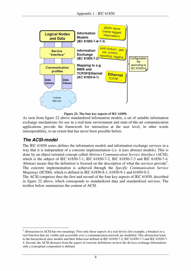
Appendix 1 - IEC 61850
4
Figure 22: The four key aspects of IEC 61850.
As seen from figure 22 above standardized information models, a set of suitable information exchange mechanisms for use in a real-time environment and state-of-the-art communication applications provide the framework for interaction at the user level, in other words interoperability, to an extent that has never been possible before.
The ACSI-model The IEC 61850 series defines the information models and information exchange services in a way that it is independent of a concrete implementation (i.e. it uses abstract models). This is done by an object-oriented concept called Abstract Communication Service Interface (ACSI), which is the subject of IEC 61850-7-1, IEC 61850-7-2, IEC 61850-7-3 and IEC 61850-7-4. Abstract means that the definition is focused on the description of what the services provide2. The concrete implementation is achieved through the Specific Communication Service Mappings (SCSM), which is defined in IEC 61850-8-1, 61850-9-1 and 61850-9-2. The ACSI comprises thus the first and second of the four key aspects of IEC 61850, described in figure 22 above, which corresponds to standardized data and standardized services. The textbox below summarizes the content of ACSI.
2 Abstraction in ACSI has two meanings. First only those aspects of a real device (for example, a breaker) or a real function that are visible and accessible over a communication network are modelled. This abstraction leads to the hierarchical class models and their behaviour defined in IEC 61850-7-2, IEC 61850-7-3 and IEC 61850-7-4. Second, the ACSI abstracts from the aspect of concrete definitions on how the devices exchange information; only a conceptual cooperation is defined.
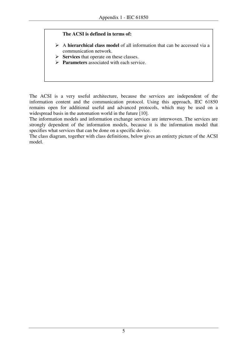
Appendix 1 - IEC 61850
5
The ACSI is a very useful architecture, because the services are independent of the information content and the communication protocol. Using this approach, IEC 61850 remains open for additional useful and advanced protocols, which may be used on a widespread basis in the automation world in the future [10]. The information models and information exchange services are interwoven. The services are strongly dependent of the information models, because it is the information model that specifies what services that can be done on a specific device. The class diagram, together with class definitions, below gives an entirety picture of the ACSI model.
The ACSI is defined in terms of:
� A hierarchical class model of all information that can be accessed via a communication network.
� Services that operate on these classes. � Parameters associated with each service.
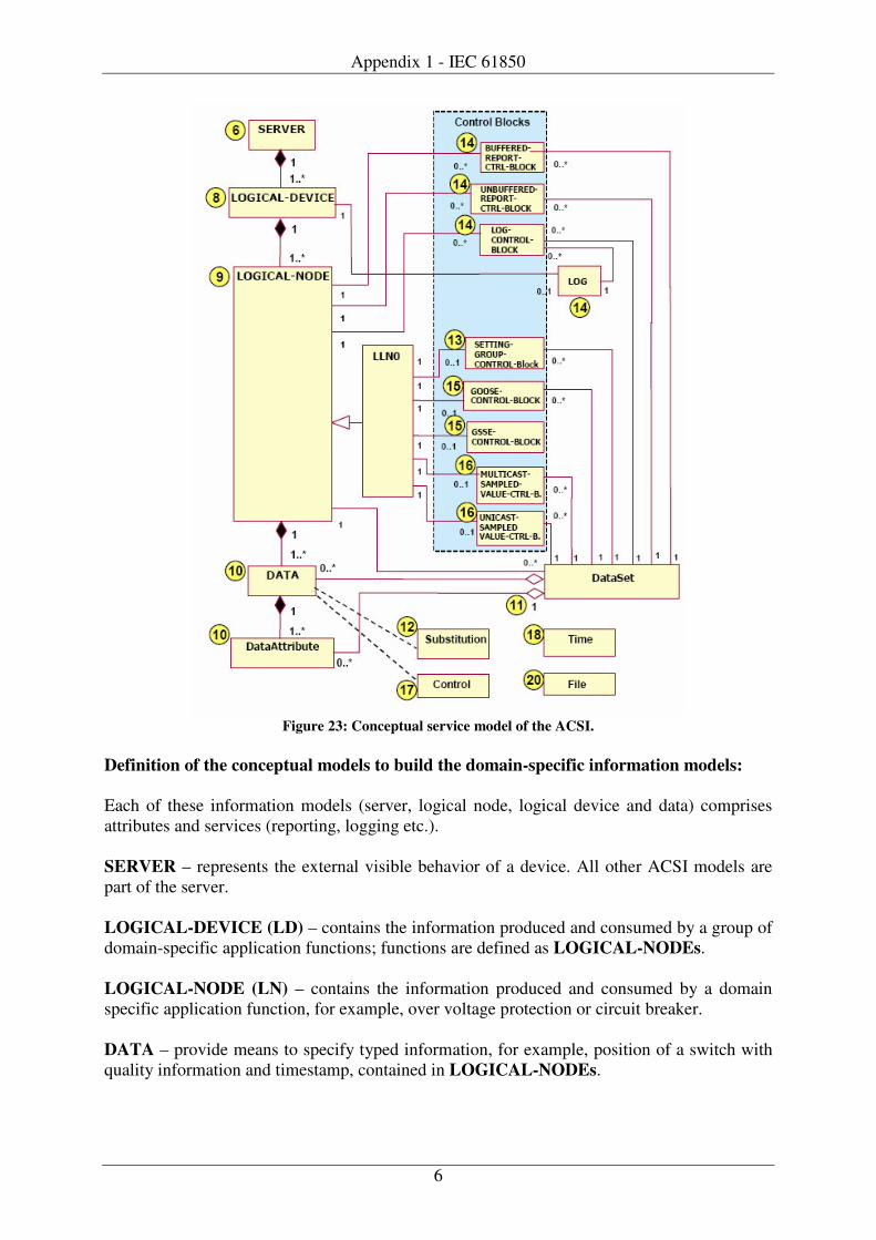
Appendix 1 - IEC 61850
6
Figure 23: Conceptual service model of the ACSI.
Definition of the conceptual models to build the domain-specific information models: Each of these information models (server, logical node, logical device and data) comprises attributes and services (reporting, logging etc.). SERVER – represents the external visible behavior of a device. All other ACSI models are part of the server. LOGICAL-DEVICE (LD) – contains the information produced and consumed by a group of domain-specific application functions; functions are defined as LOGICAL-NODEs. LOGICAL-NODE (LN) – contains the information produced and consumed by a domain specific application function, for example, over voltage protection or circuit breaker. DATA – provide means to specify typed information, for example, position of a switch with quality information and timestamp, contained in LOGICAL-NODEs.
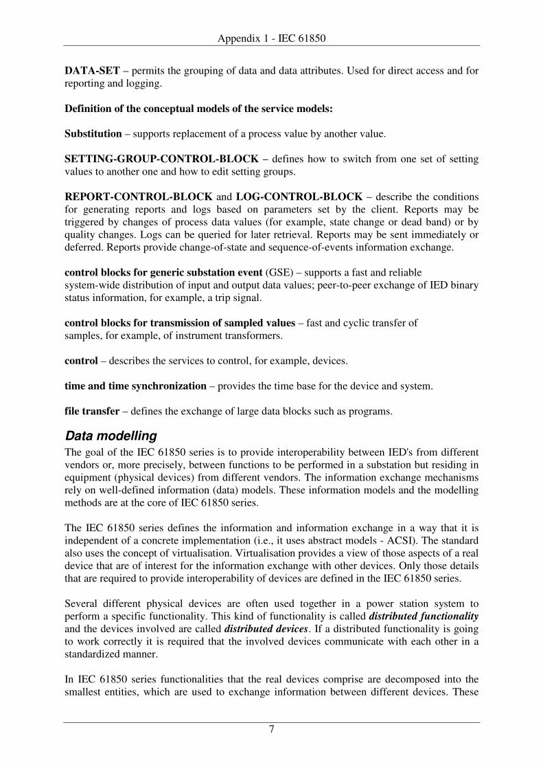
Appendix 1 - IEC 61850
7
DATA-SET – permits the grouping of data and data attributes. Used for direct access and for reporting and logging. Definition of the conceptual models of the service models: Substitution – supports replacement of a process value by another value. SETTING-GROUP-CONTROL-BLOCK – defines how to switch from one set of setting values to another one and how to edit setting groups. REPORT-CONTROL-BLOCK and LOG-CONTROL-BLOCK – describe the conditions for generating reports and logs based on parameters set by the client. Reports may be triggered by changes of process data values (for example, state change or dead band) or by quality changes. Logs can be queried for later retrieval. Reports may be sent immediately or deferred. Reports provide change-of-state and sequence-of-events information exchange. control blocks for generic substation event (GSE) – supports a fast and reliable system-wide distribution of input and output data values; peer-to-peer exchange of IED binary status information, for example, a trip signal. control blocks for transmission of sampled values – fast and cyclic transfer of samples, for example, of instrument transformers. control – describes the services to control, for example, devices. time and time synchronization – provides the time base for the device and system. file transfer – defines the exchange of large data blocks such as programs.
Data modelling The goal of the IEC 61850 series is to provide interoperability between IED's from different vendors or, more precisely, between functions to be performed in a substation but residing in equipment (physical devices) from different vendors. The information exchange mechanisms rely on well-defined information (data) models. These information models and the modelling methods are at the core of IEC 61850 series. The IEC 61850 series defines the information and information exchange in a way that it is independent of a concrete implementation (i.e., it uses abstract models - ACSI). The standard also uses the concept of virtualisation. Virtualisation provides a view of those aspects of a real device that are of interest for the information exchange with other devices. Only those details that are required to provide interoperability of devices are defined in the IEC 61850 series. Several different physical devices are often used together in a power station system to perform a specific functionality. This kind of functionality is called distributed functionality and the devices involved are called distributed devices. If a distributed functionality is going to work correctly it is required that the involved devices communicate with each other in a standardized manner. In IEC 61850 series functionalities that the real devices comprise are decomposed into the smallest entities, which are used to exchange information between different devices. These
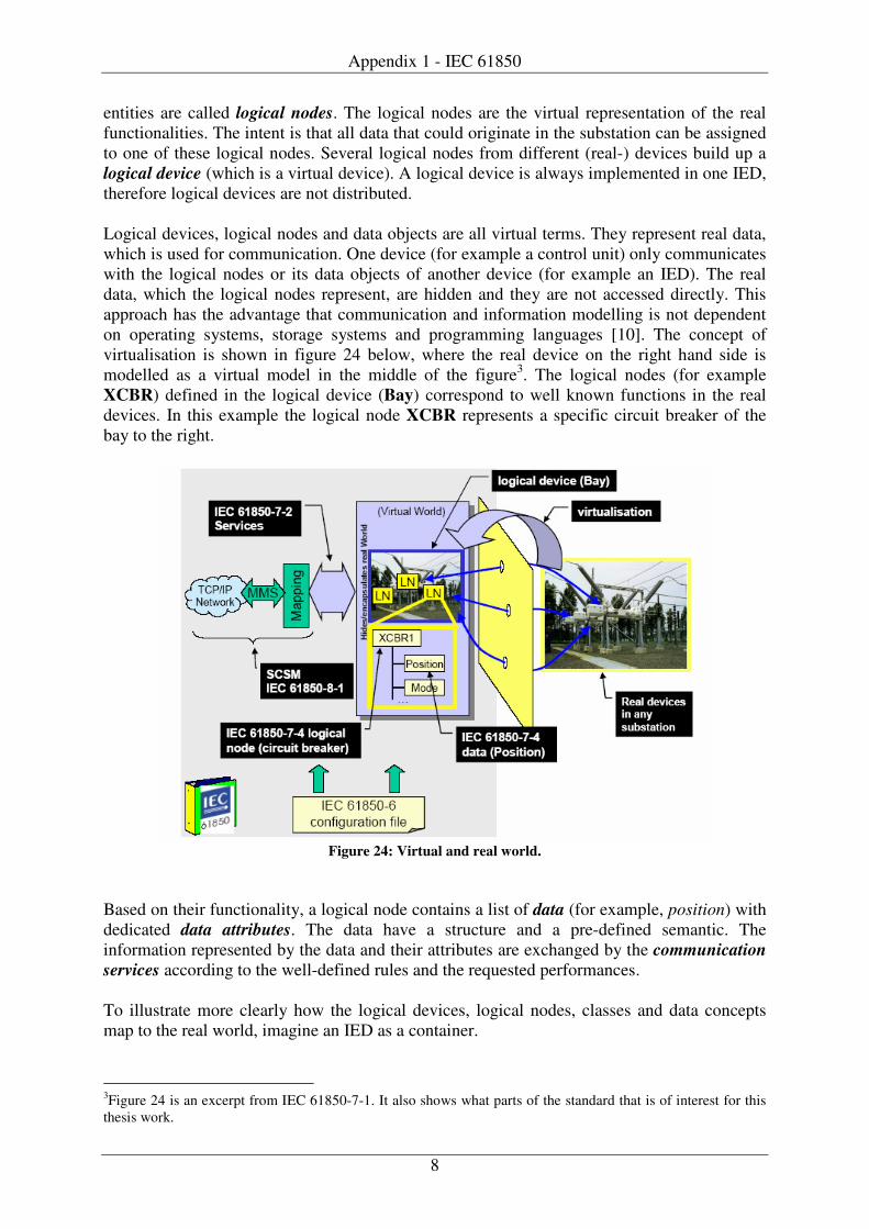
Appendix 1 - IEC 61850
8
entities are called logical nodes. The logical nodes are the virtual representation of the real functionalities. The intent is that all data that could originate in the substation can be assigned to one of these logical nodes. Several logical nodes from different (real-) devices build up a logical device (which is a virtual device). A logical device is always implemented in one IED, therefore logical devices are not distributed. Logical devices, logical nodes and data objects are all virtual terms. They represent real data, which is used for communication. One device (for example a control unit) only communicates with the logical nodes or its data objects of another device (for example an IED). The real data, which the logical nodes represent, are hidden and they are not accessed directly. This approach has the advantage that communication and information modelling is not dependent on operating systems, storage systems and programming languages [10]. The concept of virtualisation is shown in figure 24 below, where the real device on the right hand side is modelled as a virtual model in the middle of the figure3. The logical nodes (for example XCBR) defined in the logical device (Bay) correspond to well known functions in the real devices. In this example the logical node XCBR represents a specific circuit breaker of the bay to the right.
Figure 24: Virtual and real world.
Based on their functionality, a logical node contains a list of data (for example, position) with dedicated data attributes. The data have a structure and a pre-defined semantic. The information represented by the data and their attributes are exchanged by the communication services according to the well-defined rules and the requested performances.
To illustrate more clearly how the logical devices, logical nodes, classes and data concepts map to the real world, imagine an IED as a container.
3Figure 24 is an excerpt from IEC 61850-7-1. It also shows what parts of the standard that is of interest for this thesis work.
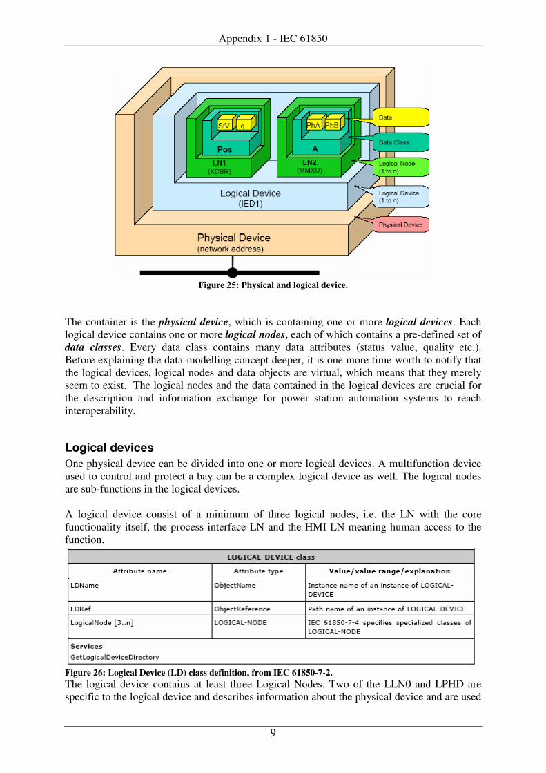
Appendix 1 - IEC 61850
9
Figure 25: Physical and logical device.
The container is the physical device, which is containing one or more logical devices. Each logical device contains one or more logical nodes, each of which contains a pre-defined set of data classes. Every data class contains many data attributes (status value, quality etc.). Before explaining the data-modelling concept deeper, it is one more time worth to notify that the logical devices, logical nodes and data objects are virtual, which means that they merely seem to exist. The logical nodes and the data contained in the logical devices are crucial for the description and information exchange for power station automation systems to reach interoperability.
Logical devices One physical device can be divided into one or more logical devices. A multifunction device used to control and protect a bay can be a complex logical device as well. The logical nodes are sub-functions in the logical devices. A logical device consist of a minimum of three logical nodes, i.e. the LN with the core functionality itself, the process interface LN and the HMI LN meaning human access to the function.
Figure 26: Logical Device (LD) class definition, from IEC 61850-7-2. The logical device contains at least three Logical Nodes. Two of the LLN0 and LPHD are specific to the logical device and describes information about the physical device and are used
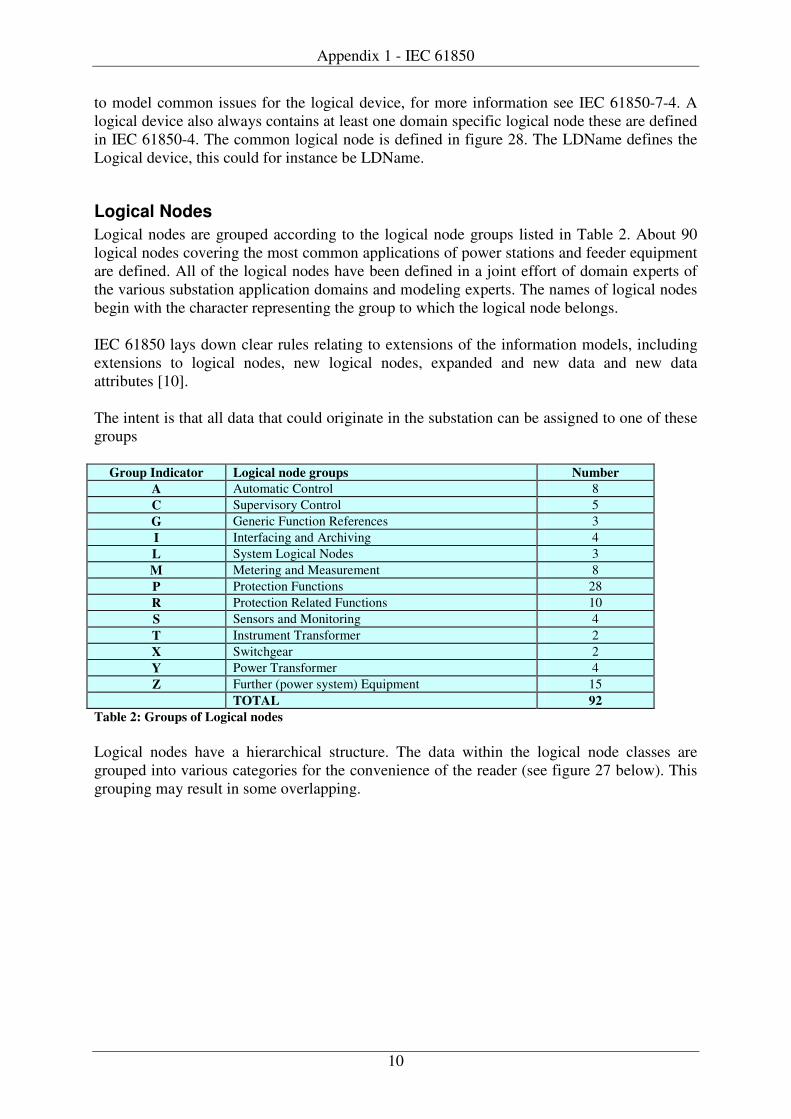
Appendix 1 - IEC 61850
10
to model common issues for the logical device, for more information see IEC 61850-7-4. A logical device also always contains at least one domain specific logical node these are defined in IEC 61850-4. The common logical node is defined in figure 28. The LDName defines the Logical device, this could for instance be LDName.
Logical Nodes Logical nodes are grouped according to the logical node groups listed in Table 2. About 90 logical nodes covering the most common applications of power stations and feeder equipment are defined. All of the logical nodes have been defined in a joint effort of domain experts of the various substation application domains and modeling experts. The names of logical nodes begin with the character representing the group to which the logical node belongs. IEC 61850 lays down clear rules relating to extensions of the information models, including extensions to logical nodes, new logical nodes, expanded and new data and new data attributes [10]. The intent is that all data that could originate in the substation can be assigned to one of these groups
Group Indicator Logical node groups Number A Automatic Control 8 C Supervisory Control 5 G Generic Function References 3 I Interfacing and Archiving 4 L System Logical Nodes 3 M Metering and Measurement 8 P Protection Functions 28 R Protection Related Functions 10 S Sensors and Monitoring 4 T Instrument Transformer 2 X Switchgear 2 Y Power Transformer 4 Z Further (power system) Equipment 15 TOTAL 92
Table 2: Groups of Logical nodes Logical nodes have a hierarchical structure. The data within the logical node classes are grouped into various categories for the convenience of the reader (see figure 27 below). This grouping may result in some overlapping.
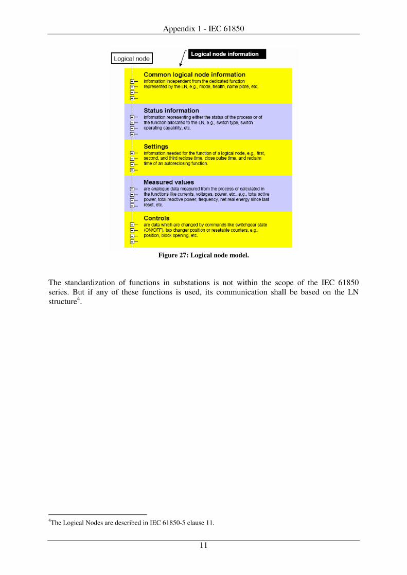
Appendix 1 - IEC 61850
11
Figure 27: Logical node model.
The standardization of functions in substations is not within the scope of the IEC 61850 series. But if any of these functions is used, its communication shall be based on the LN structure4.
4The Logical Nodes are described in IEC 61850-5 clause 11.
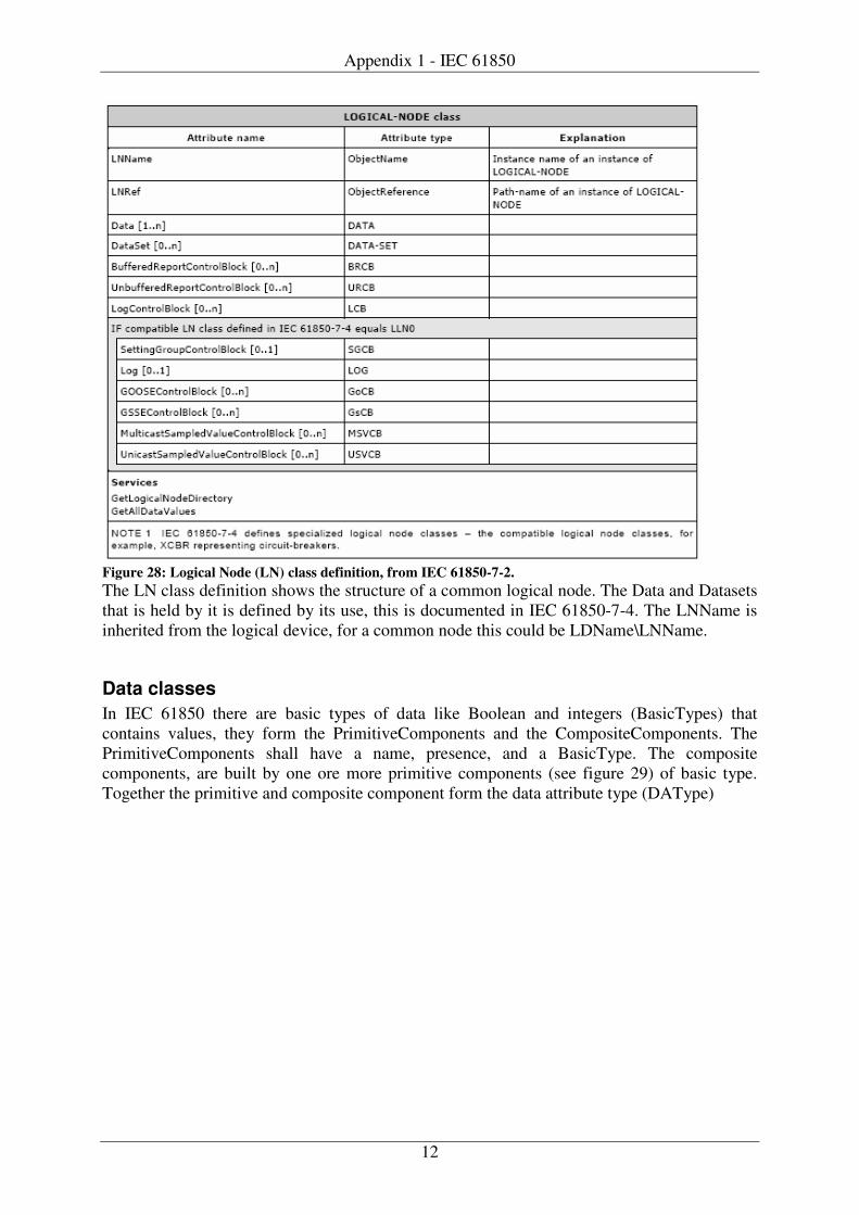
Appendix 1 - IEC 61850
12
Figure 28: Logical Node (LN) class definition, from IEC 61850-7-2. The LN class definition shows the structure of a common logical node. The Data and Datasets that is held by it is defined by its use, this is documented in IEC 61850-7-4. The LNName is inherited from the logical device, for a common node this could be LDName\LNName.
Data classes In IEC 61850 there are basic types of data like Boolean and integers (BasicTypes) that contains values, they form the PrimitiveComponents and the CompositeComponents. The PrimitiveComponents shall have a name, presence, and a BasicType. The composite components, are built by one ore more primitive components (see figure 29) of basic type. Together the primitive and composite component form the data attribute type (DAType)

Appendix 1 - IEC 61850
13
Figure 29: Class diagram of DATA and Data Attribute. The DATA is a class that has a Data name, a presence and DataAttributes. The DataAttributes are used to form a simple common data class (SimpleCDC) and the composite common data class (CompositeCDC). The CompositeCDC is constructed by on or more SimpleCDC and or DataAttributes. Figure 30 shows an example of Data classes, data components and data attributes.
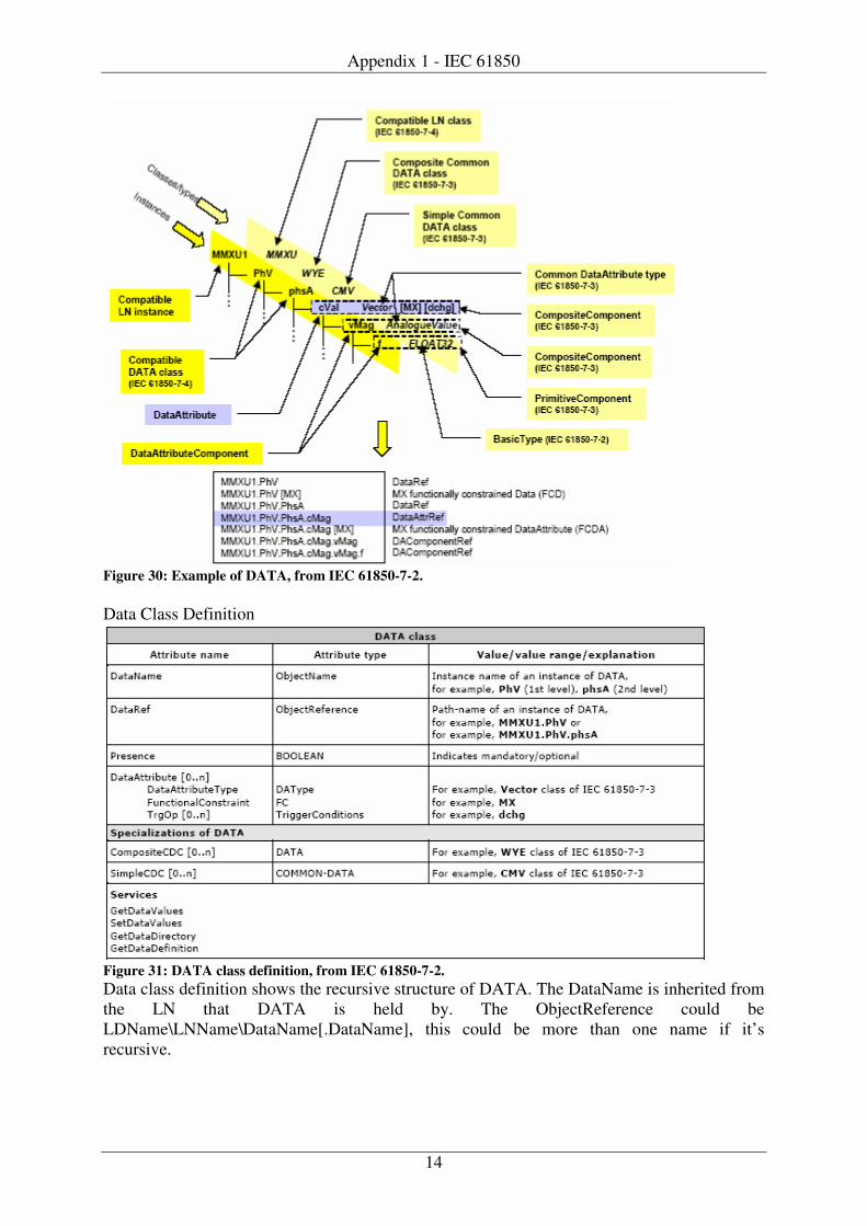
Appendix 1 - IEC 61850
14
Figure 30: Example of DATA, from IEC 61850-7-2. Data Class Definition
Figure 31: DATA class definition, from IEC 61850-7-2. Data class definition shows the recursive structure of DATA. The DataName is inherited from the LN that DATA is held by. The ObjectReference could be LDName\LNName\DataName[.DataName], this could be more than one name if it’s recursive.
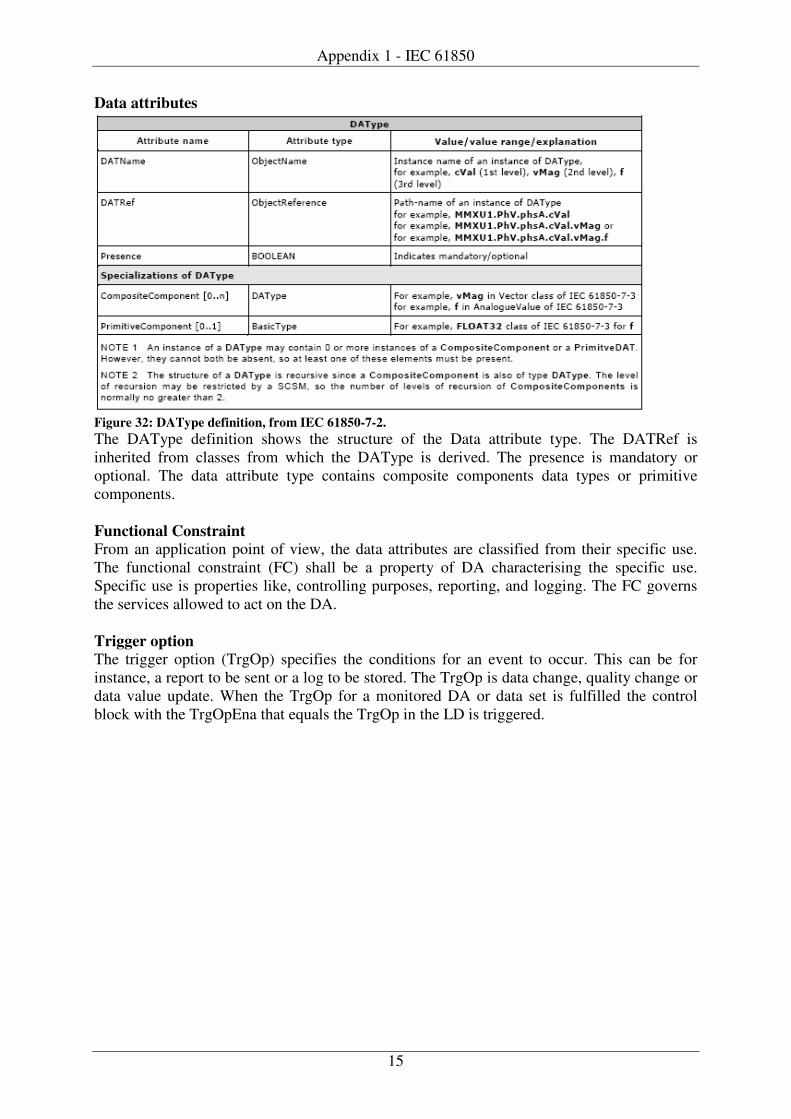
Appendix 1 - IEC 61850
15
Data attributes
Figure 32: DAType definition, from IEC 61850-7-2. The DAType definition shows the structure of the Data attribute type. The DATRef is inherited from classes from which the DAType is derived. The presence is mandatory or optional. The data attribute type contains composite components data types or primitive components. Functional Constraint From an application point of view, the data attributes are classified from their specific use. The functional constraint (FC) shall be a property of DA characterising the specific use. Specific use is properties like, controlling purposes, reporting, and logging. The FC governs the services allowed to act on the DA. Trigger option The trigger option (TrgOp) specifies the conditions for an event to occur. This can be for instance, a report to be sent or a log to be stored. The TrgOp is data change, quality change or data value update. When the TrgOp for a monitored DA or data set is fulfilled the control block with the TrgOpEna that equals the TrgOp in the LD is triggered.
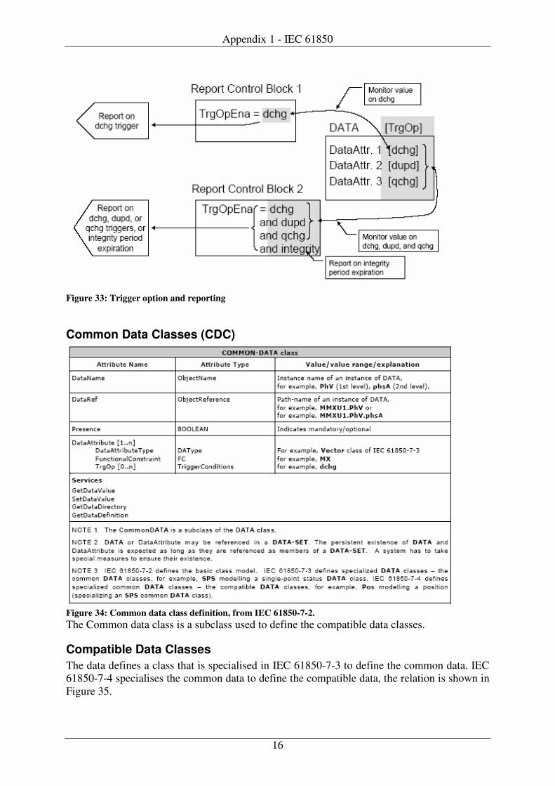
Appendix 1 - IEC 61850
16
Figure 33: Trigger option and reporting
Common Data Classes (CDC)
Figure 34: Common data class definition, from IEC 61850-7-2. The Common data class is a subclass used to define the compatible data classes.
Compatible Data Classes The data defines a class that is specialised in IEC 61850-7-3 to define the common data. IEC 61850-7-4 specialises the common data to define the compatible data, the relation is shown in Figure 35.

Appendix 1 - IEC 61850
17
Figure 35: relation of data class.
Data set A Data set is a ordered group of object references of data or data attributes (known as data set members), organised as a single collection for convenience for the client. The object references shall be known to both the server and the clients so that only the name of the data set and the values needs to be transmitted. There are two types of data sets, a persistent and a non-persistent instance of data set. The persistent instance of data set shall be visible to clients of any two party application association. Non-persistent instances shall only be visible to the client that created the data set. Pre-configured data sets shall be visible to clients of any two party application association and shall be non-deletable.
Figure 36: Data set definition
Communication services The ACSI model basically provides the methods of exchanging information between devices as shown in figure 37.
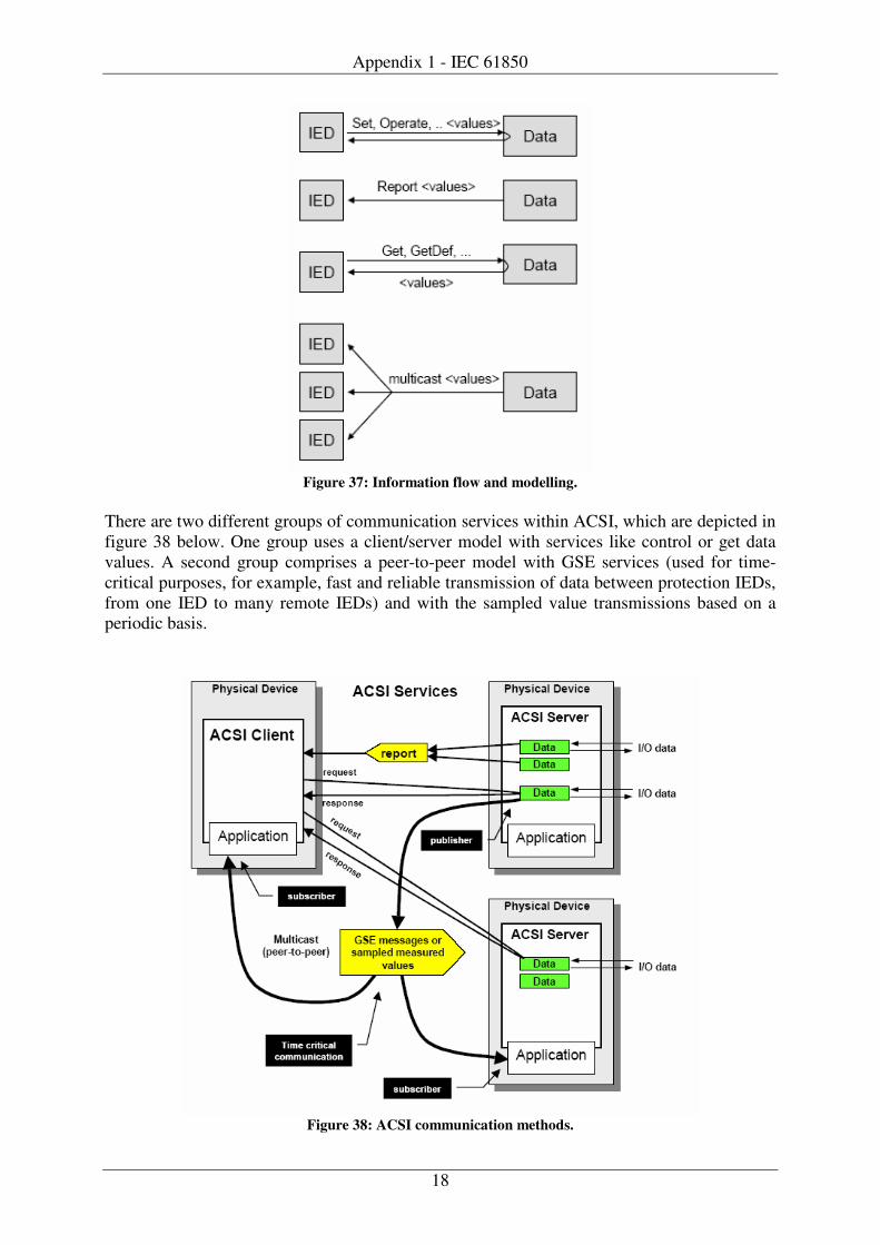
Appendix 1 - IEC 61850
18
Figure 37: Information flow and modelling.
There are two different groups of communication services within ACSI, which are depicted in figure 38 below. One group uses a client/server model with services like control or get data values. A second group comprises a peer-to-peer model with GSE services (used for time-critical purposes, for example, fast and reliable transmission of data between protection IEDs, from one IED to many remote IEDs) and with the sampled value transmissions based on a periodic basis.
Figure 38: ACSI communication methods.
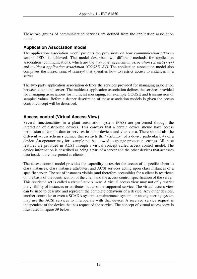
Appendix 1 - IEC 61850
19
These two groups of communication services are defined from the application association model.
Application Association model The application association model presents the provisions on how communication between several IEDs is achieved. The model describes two different methods for application association (communication), which are the two-party application association (client/server) and multicast application association (GOOSE, SV). The application association model also comprises the access control concept that specifies how to restrict access to instances in a server. The two party application association defines the services provided for managing association between client and server. The multicast application association defines the services provided for managing associations for multicast messaging, for example GOOSE and transmission of sampled values. Before a deeper description of these association models is given the access control concept will be described.
Access control (Virtual Access View) Several functionalities in a plant automation system (PAS) are performed through the interaction of distributed devices. This conveys that a certain device should have access permission to certain data or services in other devices and vice versa. There should also be different access schemes defined that restricts the "visibility" of a device particular data of a device. An operator may for example not be allowed to change protection settings. All these features are provided in ACSI through a virtual concept called access control model. The device information is described as being a part of a server and the other devices that accesses data inside it are interpreted as clients.
The access control model provides the capability to restrict the access of a specific client to class instances, class instance attributes, and ACSI services acting upon class instances of a specific server. The set of instances visible (and therefore accessible) for a client is restricted on the basis of the identification of the client and the access control specification of the server. This restricted set is called a virtual access view. A virtual access view may not only restrict the visibility of instances or attributes but also the supported service. The virtual access view can be used to describe and represent the complete behaviour of a device. Any other devices, another controller or even a SCADA system, a maintenance system, or an engineering system may use the ACSI services to interoperate with that device. A received service request is independent of the device that has requested the service. The concept of virtual access view is illustrated in figure 39 below.
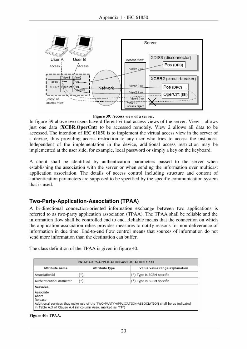
Appendix 1 - IEC 61850
20
Figure 39: Access view of a server.
In figure 39 above two users have different virtual access views of the server. View 1 allows just one data (XCBR.OperCnt) to be accessed remotely. View 2 allows all data to be accessed. The intention of IEC 61850 is to implement the virtual access view in the server of a device, thus providing access restriction to any user who tries to access the instances. Independent of the implementation in the device, additional access restriction may be implemented at the user side, for example, local password or simply a key on the keyboard. A client shall be identified by authentication parameters passed to the server when establishing the association with the server or when sending the information over multicast application association. The details of access control including structure and content of authentication parameters are supposed to be specified by the specific communication system that is used.
Two-Party-Application-Association (TPAA) A bi-directional connection-oriented information exchange between two applications is referred to as two-party application association (TPAA). The TPAA shall be reliable and the information flow shall be controlled end to end. Reliable means that the connection on which the application association relies provides measures to notify reasons for non-deliverance of information in due time. End-to-end flow control means that sources of information do not send more information than the destination can buffer. The class definition of the TPAA is given in figure 40.
Figure 40: TPAA.
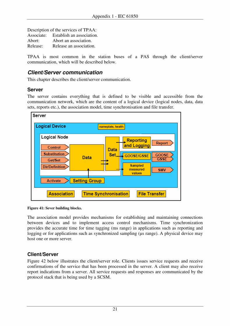
Appendix 1 - IEC 61850
21
Description of the services of TPAA: Associate: Establish an association. Abort: Abort an association. Release: Release an association. TPAA is most common in the station buses of a PAS through the client/server communication, which will be described below.
Client/Server communication This chapter describes the client/server communication.
Server The server contains everything that is defined to be visible and accessible from the communication network, which are the content of a logical device (logical nodes, data, data sets, reports etc.), the association model, time synchronisation and file transfer.
Figure 41: Sever building blocks. The association model provides mechanisms for establishing and maintaining connections between devices and to implement access control mechanisms. Time synchronization provides the accurate time for time tagging (ms range) in applications such as reporting and logging or for applications such as synchronized sampling (�s range). A physical device may host one or more server.
Client/Server Figure 42 below illustrates the client/server role. Clients issues service requests and receive confirmations of the service that has been processed in the server. A client may also receive report indications from a server. All service requests and responses are communicated by the protocol stack that is being used by a SCSM.
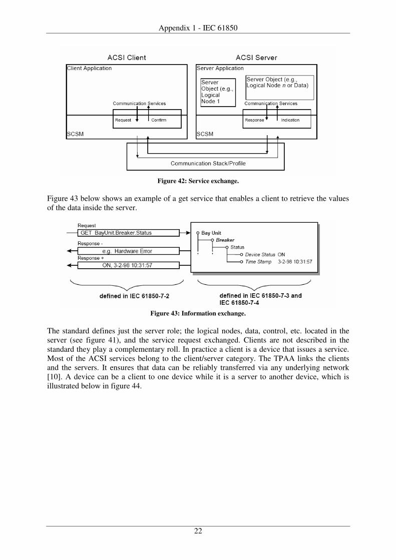
Appendix 1 - IEC 61850
22
Figure 42: Service exchange.
Figure 43 below shows an example of a get service that enables a client to retrieve the values of the data inside the server.
Figure 43: Information exchange.
The standard defines just the server role; the logical nodes, data, control, etc. located in the server (see figure 41), and the service request exchanged. Clients are not described in the standard they play a complementary roll. In practice a client is a device that issues a service. Most of the ACSI services belong to the client/server category. The TPAA links the clients and the servers. It ensures that data can be reliably transferred via any underlying network [10]. A device can be a client to one device while it is a server to another device, which is illustrated below in figure 44.
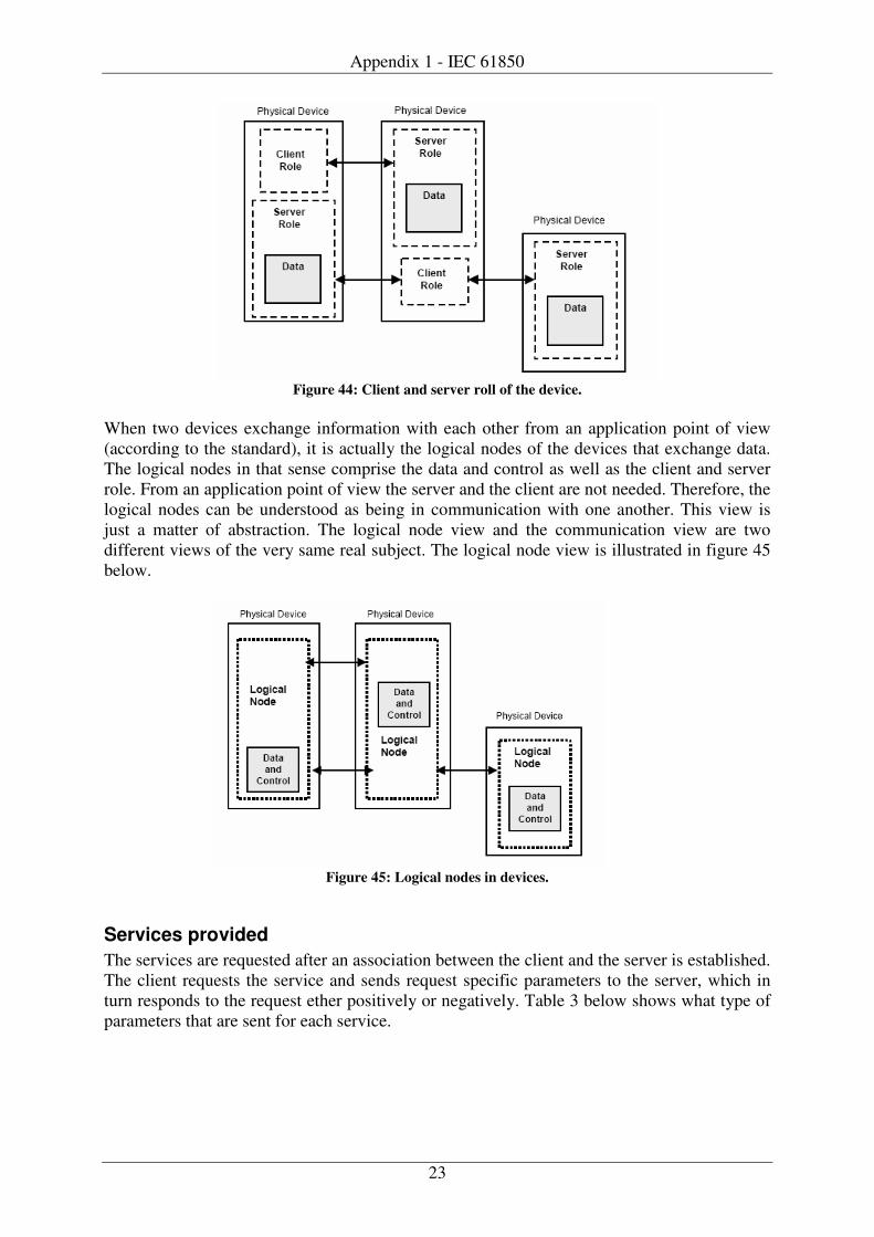
Appendix 1 - IEC 61850
23
Figure 44: Client and server roll of the device.
When two devices exchange information with each other from an application point of view (according to the standard), it is actually the logical nodes of the devices that exchange data. The logical nodes in that sense comprise the data and control as well as the client and server role. From an application point of view the server and the client are not needed. Therefore, the logical nodes can be understood as being in communication with one another. This view is just a matter of abstraction. The logical node view and the communication view are two different views of the very same real subject. The logical node view is illustrated in figure 45 below.
Figure 45: Logical nodes in devices.
Services provided The services are requested after an association between the client and the server is established. The client requests the service and sends request specific parameters to the server, which in turn responds to the request ether positively or negatively. Table 3 below shows what type of parameters that are sent for each service.
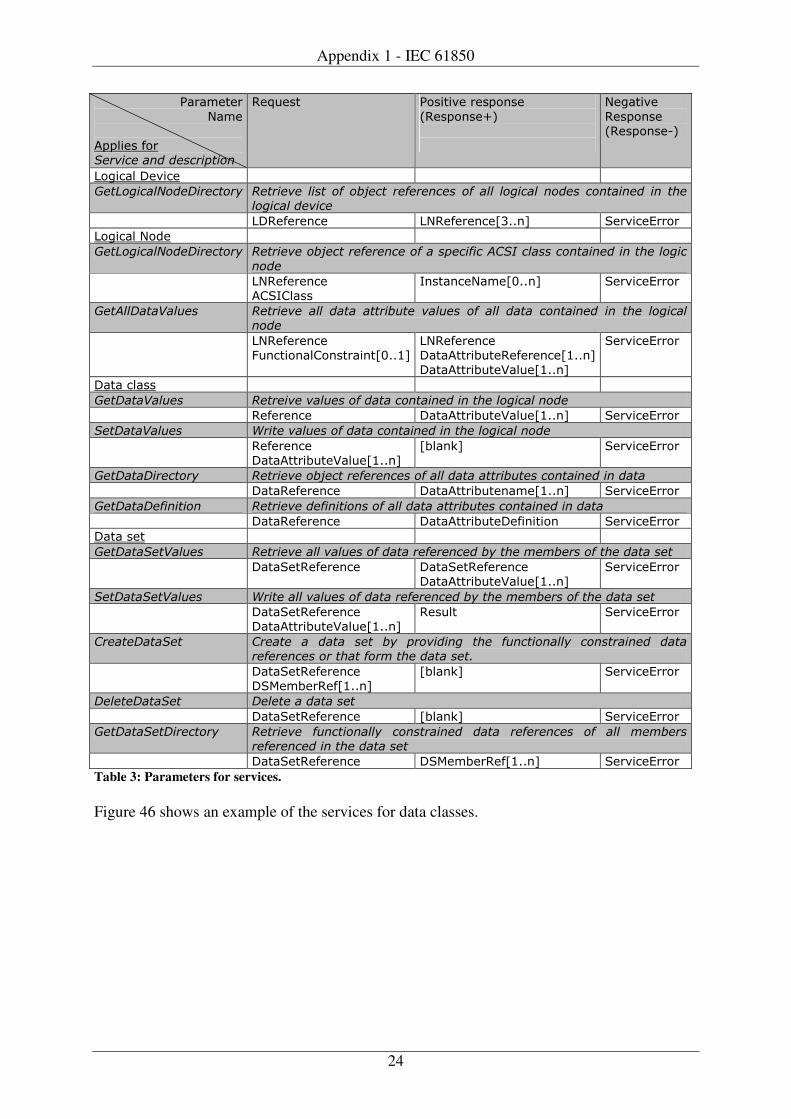
Appendix 1 - IEC 61850
24
#�"�����"
���� ����� ��" ���������������� ���
.��/��� #�����(� "������
0.������12
��!���(�
.������ 0.������32
��!���� ��(���
�� ��������������� ���� �� ��������� � �������� � ���������� ������������������� �� ���� �� ���
��������������
��.���"���� ��.���"����45���6 $�"(���7""�"
��!���� ����
�� ��������������� ���� �� ����������� ������������������������������������� ������ ���������
���
��.���"���� ��$*�����
*�����������4+���6 $�"(���7""�"
�� ����� �������� �� ������ ���� � �� � ���� �� ������� ��� ���� � �� �� ���� �� �����������
���
��.���"���� -/�������������"����4+��)6
��.���"���� �������"��/��.���"����4)���6 �������"��/��8��/�4)���6
$�"(���7""�"
���� �����
�� �� �������� �� ����������������� ���� ������ ��������������
.���"���� �������"��/��8��/�4)���6 $�"(���7""�"
�� �� �������� �� ������������� ���� ������ ��������������
.���"���� �������"��/��8��/�4)���6
4����96 $�"(���7""�"
�� �� ������ ���� �� ����������� ������������������� ��� ���� ����� ������� ��
����.���"���� �������"��/������4)���6 $�"(���7""�"
�� �� ������ ��� �� ���������� ������������ ��� ���� ����� ������� ��
����.���"���� �������"��/������������ $�"(���7""�"
���� ���
�� �� ��� ������� �� ��������������������� �������������� ���!�!�������� ���� ���� �
����$��.���"���� ����$��.���"���� �������"��/��8��/�4)���6
$�"(���7""�"
�� �� ��� ������� �� ����������������� �������������� ���!�!�������� ���� ���� �
����$��.���"���� �������"��/��8��/�4)���6
.��/�� $�"(���7""�"
���� ��� ��� � ���� �� �� � �� �� � ��� �������� ��� ��� ������� ��� ����� � ��
������������� �� ����!� ���� ���� "�
����$��.���"���� �$&����".��4)���6
4����96 $�"(���7""�"
���� ��� ��� � ���� ����� ���� �
����$��.���"���� 4����96 $�"(���7""�"
�� �� ��� ����� ���� �� ������ ��� ������� ��� ����� � �� ���������� ��� ���� !�!�����
����������� ���� ���� �
����$��.���"���� �$&����".��4)���6 $�"(���7""�"
Table 3: Parameters for services. Figure 46 shows an example of the services for data classes.
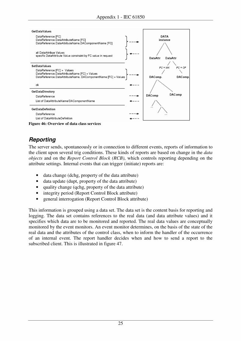
Appendix 1 - IEC 61850
25
Figure 46: Overview of data class services
Reporting The server sends, spontaneously or in connection to different events, reports of information to the client upon several trig conditions. These kinds of reports are based on change in the data objects and on the Report Control Block (RCB), which controls reporting depending on the attribute settings. Internal events that can trigger (initiate) reports are:
• data change (dchg, property of the data attribute) • data update (dupt, property of the data attribute) • quality change (qchg, property of the data attribute) • integrity period (Report Control Block attribute) • general interrogation (Report Control Block attribute)
This information is grouped using a data set. The data set is the content basis for reporting and logging. The data set contains references to the real data (and data attribute values) and it specifies which data are to be monitored and reported. The real data values are conceptually monitored by the event monitors. An event monitor determines, on the basis of the state of the real data and the attributes of the control class, when to inform the handler of the occurrence of an internal event. The report handler decides when and how to send a report to the subscribed client. This is illustrated in figure 47.
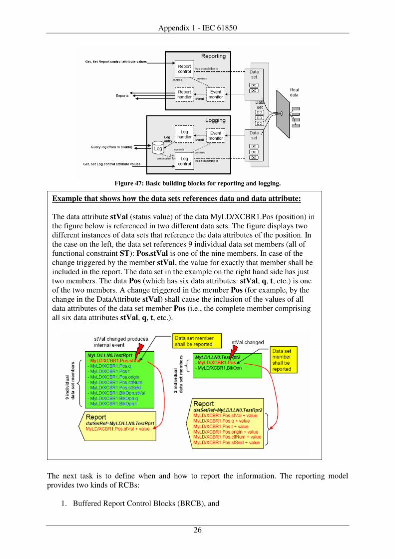
Appendix 1 - IEC 61850
26
Figure 47: Basic building blocks for reporting and logging.
The next task is to define when and how to report the information. The reporting model provides two kinds of RCBs:
1. Buffered Report Control Blocks (BRCB), and
Example that shows how the data sets references data and data attribute: The data attribute stVal (status value) of the data MyLD/XCBR1.Pos (position) in the figure below is referenced in two different data sets. The figure displays two different instances of data sets that reference the data attributes of the position. In the case on the left, the data set references 9 individual data set members (all of functional constraint ST): Pos.stVal is one of the nine members. In case of the change triggered by the member stVal, the value for exactly that member shall be included in the report. The data set in the example on the right hand side has just two members. The data Pos (which has six data attributes: stVal, q, t, etc.) is one of the two members. A change triggered in the member Pos (for example, by the change in the DataAttribute stVal) shall cause the inclusion of the values of all data attributes of the data set member Pos (i.e., the complete member comprising all six data attributes stVal, q, t, etc.).
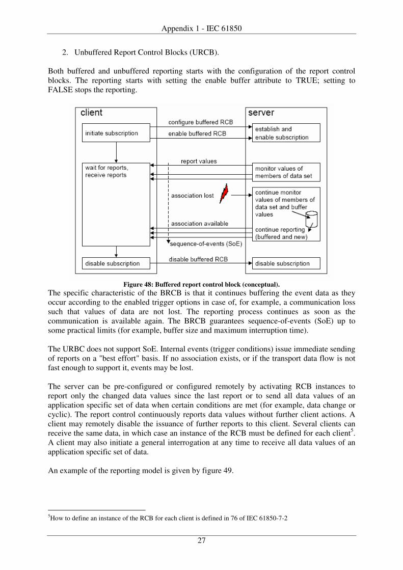
Appendix 1 - IEC 61850
27
2. Unbuffered Report Control Blocks (URCB). Both buffered and unbuffered reporting starts with the configuration of the report control blocks. The reporting starts with setting the enable buffer attribute to TRUE; setting to FALSE stops the reporting.
Figure 48: Buffered report control block (conceptual).
The specific characteristic of the BRCB is that it continues buffering the event data as they occur according to the enabled trigger options in case of, for example, a communication loss such that values of data are not lost. The reporting process continues as soon as the communication is available again. The BRCB guarantees sequence-of-events (SoE) up to some practical limits (for example, buffer size and maximum interruption time). The URBC does not support SoE. Internal events (trigger conditions) issue immediate sending of reports on a "best effort" basis. If no association exists, or if the transport data flow is not fast enough to support it, events may be lost. The server can be pre-configured or configured remotely by activating RCB instances to report only the changed data values since the last report or to send all data values of an application specific set of data when certain conditions are met (for example, data change or cyclic). The report control continuously reports data values without further client actions. A client may remotely disable the issuance of further reports to this client. Several clients can receive the same data, in which case an instance of the RCB must be defined for each client5. A client may also initiate a general interrogation at any time to receive all data values of an application specific set of data. An example of the reporting model is given by figure 49.
5How to define an instance of the RCB for each client is defined in 76 of IEC 61850-7-2

Appendix 1 - IEC 61850
28
Figure 49: Reporting.
Logging Event logging directly in the automation device is described in the logging model. Logging is very similar to buffered reporting. The major difference is that with buffered reporting, the reports are always sent immediately (if no communication errors occurs). If the buffer time is not equal to zero, the report can be delayed to include other events from the data set, but the principle remains the same. With the logging model, the client actively retrieves the reports from a circular buffer in the server. Two time stamps can be assigned; the start time (or a start number for the entry) and the end time. All log entries between these two time stamps (or between the start number and the end of the log) are sent to the client [10]. Another major difference compared to BRCB is that when BRCB is used, only one client receives data. With logging, any number of clients can query entries. Queries do not change the entries. The standard describes the difference between reporting and logging according to the text below: The principal building blocks for logging are depicted in figure 50. The logging model has four building blocks. The data set represents the real data values. It is referenced in the log control block (LCB). The LCB controls which data values and when these data values are to
Reporting provides mechanisms to report packed values of instances of data immediately or after some buffer time. The logging model provides mechanisms to store events in the log in sequence. A client may query a range of log entries at any time [10].
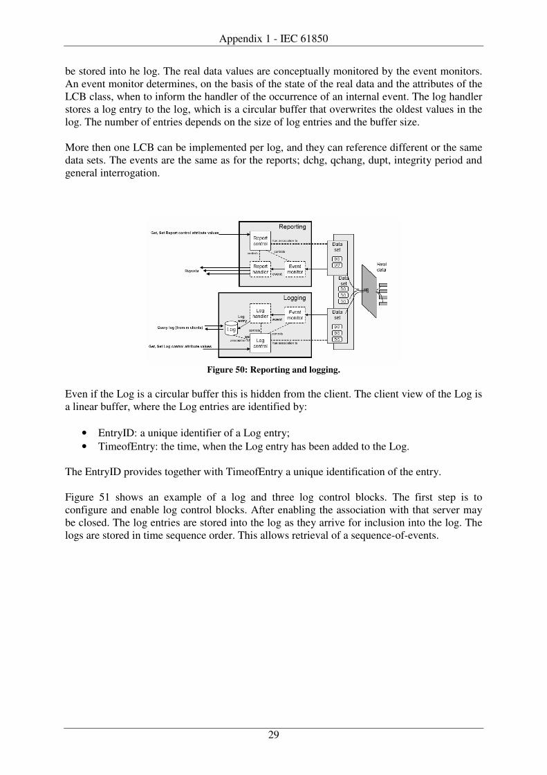
Appendix 1 - IEC 61850
29
be stored into he log. The real data values are conceptually monitored by the event monitors. An event monitor determines, on the basis of the state of the real data and the attributes of the LCB class, when to inform the handler of the occurrence of an internal event. The log handler stores a log entry to the log, which is a circular buffer that overwrites the oldest values in the log. The number of entries depends on the size of log entries and the buffer size.
More then one LCB can be implemented per log, and they can reference different or the same data sets. The events are the same as for the reports; dchg, qchang, dupt, integrity period and general interrogation.
Figure 50: Reporting and logging.
Even if the Log is a circular buffer this is hidden from the client. The client view of the Log is a linear buffer, where the Log entries are identified by:
• EntryID: a unique identifier of a Log entry; • TimeofEntry: the time, when the Log entry has been added to the Log.
The EntryID provides together with TimeofEntry a unique identification of the entry. Figure 51 shows an example of a log and three log control blocks. The first step is to configure and enable log control blocks. After enabling the association with that server may be closed. The log entries are stored into the log as they arrive for inclusion into the log. The logs are stored in time sequence order. This allows retrieval of a sequence-of-events.
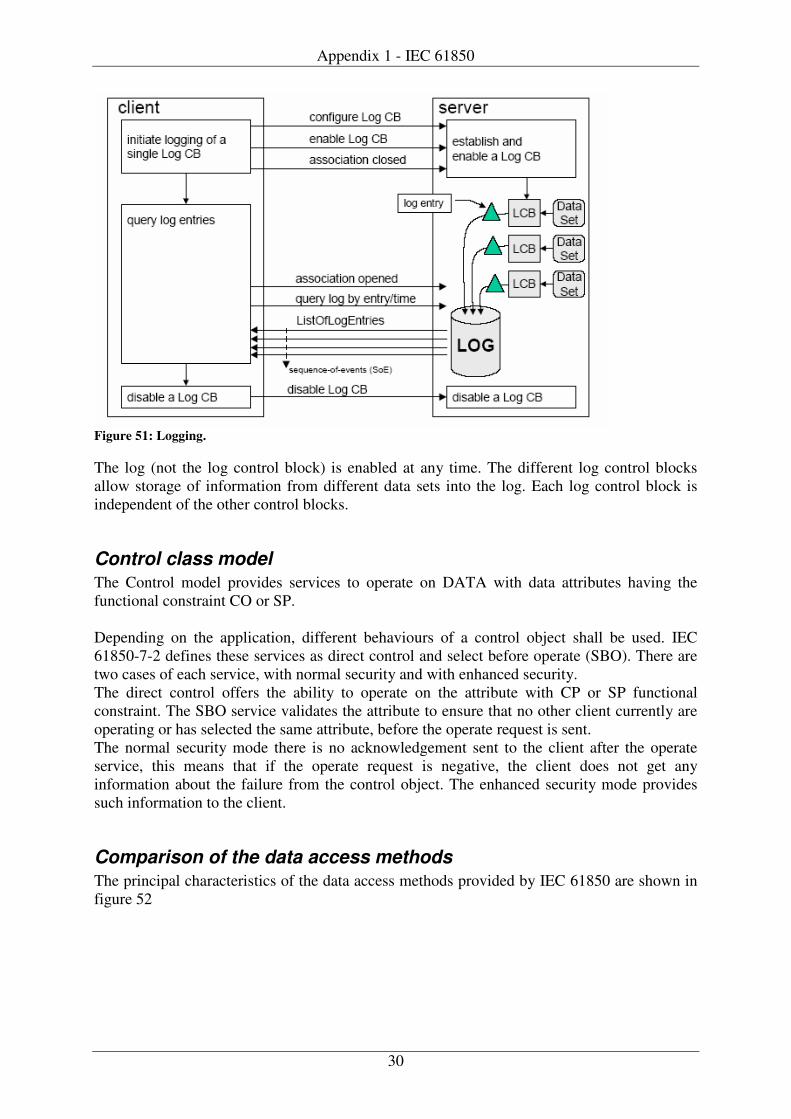
Appendix 1 - IEC 61850
30
Figure 51: Logging. The log (not the log control block) is enabled at any time. The different log control blocks allow storage of information from different data sets into the log. Each log control block is independent of the other control blocks.
Control class model The Control model provides services to operate on DATA with data attributes having the functional constraint CO or SP. Depending on the application, different behaviours of a control object shall be used. IEC 61850-7-2 defines these services as direct control and select before operate (SBO). There are two cases of each service, with normal security and with enhanced security. The direct control offers the ability to operate on the attribute with CP or SP functional constraint. The SBO service validates the attribute to ensure that no other client currently are operating or has selected the same attribute, before the operate request is sent. The normal security mode there is no acknowledgement sent to the client after the operate service, this means that if the operate request is negative, the client does not get any information about the failure from the control object. The enhanced security mode provides such information to the client.
Comparison of the data access methods The principal characteristics of the data access methods provided by IEC 61850 are shown in figure 52

Appendix 1 - IEC 61850
31
Figure 52: Comparison of data access methods. Each of the four retrieval methods has a specific characteristic. There is no single method that meets all application requirements. During system design, the designer has to analyse the requirements ant to check them against the (implemented) methods provided by a device compliant with the IEC 61850 series.
Communication mappings The abstract communication service interface (ACSI) must be implemented by means of protocols in order to use the services defined in IEC 61850. The standard describes four such mappings, specific communication service mapping (ACSI). Two that maps the client/server communication on the station bus level to existing standards. Common for the two is that both uses manufacturing message specification (MMS). MMS is a standard that have served the industry for many years, the mapping to this standard provides a robust and well tested communication service interface for IEC 61850. MMS maps to the upper layers of the stack while the lower part is mapped to Ethernet, with and without TCP/IP. The two remaining SCSM maps GOOSE and SV communication over Ethernet. And SCSM mapping for SV communication over point-to-point links. Since station bus is the focus in this work, the GOOSE and SV mapping will not be considered. IEC 61850-8-1 defines three communication profiles, two of them for layer 1-4 and one for the layers 5-7. They are referred to as A-Profile for the layers 5-7 and TCP/IP T-Profile and OSI T-Profile. The A-Profile defines the services for layer 5-7 and has the following attributes.
Figure 53: A-Profile Layer 7: MMS provides a rich set of services for peer-to-peer real-time communications over a network. [5]. MMS is used for mapping of all client/server communication in IEC 61850. Association control service element is used to establish and release an application-association between two applications and to determine the application context of that association [12].
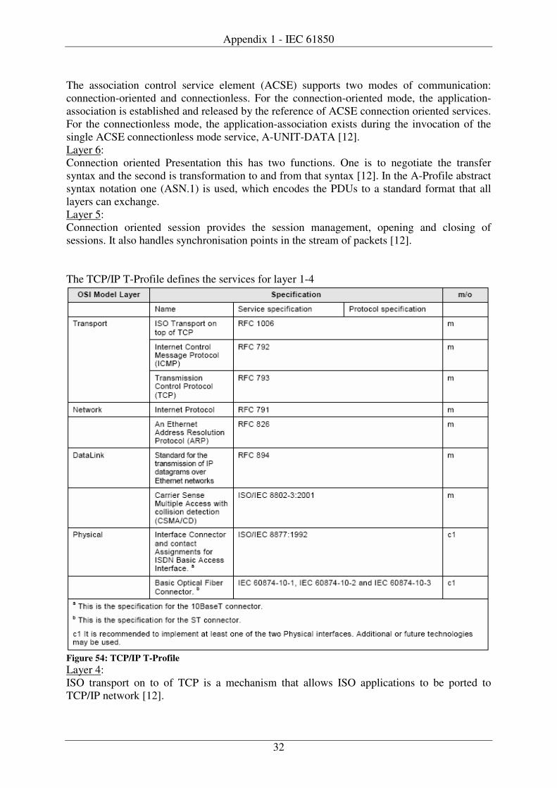
Appendix 1 - IEC 61850
32
The association control service element (ACSE) supports two modes of communication: connection-oriented and connectionless. For the connection-oriented mode, the application-association is established and released by the reference of ACSE connection oriented services. For the connectionless mode, the application-association exists during the invocation of the single ACSE connectionless mode service, A-UNIT-DATA [12]. Layer 6: Connection oriented Presentation this has two functions. One is to negotiate the transfer syntax and the second is transformation to and from that syntax [12]. In the A-Profile abstract syntax notation one (ASN.1) is used, which encodes the PDUs to a standard format that all layers can exchange. Layer 5: Connection oriented session provides the session management, opening and closing of sessions. It also handles synchronisation points in the stream of packets [12]. The TCP/IP T-Profile defines the services for layer 1-4
Figure 54: TCP/IP T-Profile Layer 4: ISO transport on to of TCP is a mechanism that allows ISO applications to be ported to TCP/IP network [12].

Appendix 1 - IEC 61850
33
Internet control message protocol is a integrated part of the IP suite , icmp messages delivered in packages are used for out-of-band messages related to network operations or mis-operations [12]. Transmission control protocol provides a reliable stream delivery and virtual connection service to applications by sequenced acknowledgment [12]. Layer 3: Internet protocol contains addressing information and control information to route packages thru the network [12]. Address resolution protocol provides mapping of the IP-address to the physical network address [12]. Layer 2: Standard for the transmission of IP datagrams over Eternet networks is a method for transmission of packages. Carrier sense multiple access with collision detection is a method to control access to the network bus [12]. Layer 1: Interface connector and contact assignment for ISDN basic access interface (ISO/IEC 8877:1992), this is the specification for 10BaseT connector. Basic optical fiber connector (IEC60874-10 –1, -2 and –3), this is the specification for the ST connector.

1
Appendix 2 - Definitions. This appendix shows the definitions of the logical nodes and the data object that where implemented during the test phase.
Logical Nodes The two definitions of the logical nodes below,
LN: Generic set-point control Name: ASPT
This LN shall be used to provide the common characteristics found in all controller or regulator type Logical Nodes. The LN can be standalone or cascaded with other logical nodes to forma a complete controller.
ASPT class
Attribute Name Attr. Type Explanation T M/O
LNName Shall be inherited from Logical-Node Class (see IEC 61850-7-2) Data
Common Logical Node Information LN shall inherit all Mandatory Data from Common Logical Node Class M Controls SptR SPC Setpoint raise O SptL SPC Setpoint lower O Measured Values ActualSet MV Actual setpoint M ErrTerm MV Error term O Output MV Output Status Information Auto SPS Automatic operation O SptDevAlm SPS Deviation alarm O SptUp SPS Setpoint going up (raising) O SptDwn SPS Setpoint going up (Lowering) O SptDir SPS Setpoint direction O SptMsg INS End Message:
0 Ended normally 1 Ended with overshoot 2 Cancelled: measurement was deviating 3 Cancelled: loss of communication with dispatch centre 4 Cancelled: loss of communication with local area network 5 Cancelled: loss of communication with the local interface 6 Cancelled: timeout 7 Cancelled: voluntarily 8 Cancelled: noisy environments 9 Cancelled: material failure A Cancelled: new set-point request B Cancelled: improper environment (blockage) C Cancelled: stability time was reached D Cancelled: immobilisation time was reached E Cancelled: equipment was in the wrong mode F Unknown causes
O
AdjMsg INS Adjustment Message 0 Completed 1 Cancelled 2 New adjustments 3 Under way
O
Settings MaxRst RST Maximum restriction O MinRst RST Minimum restriction O DevAlm ASG Deviation Alarm O SetPt APC Setpoint O DeadB ASG Deadband O Controls Blk SPS Block operation O
Table 4: ASPT logical node class
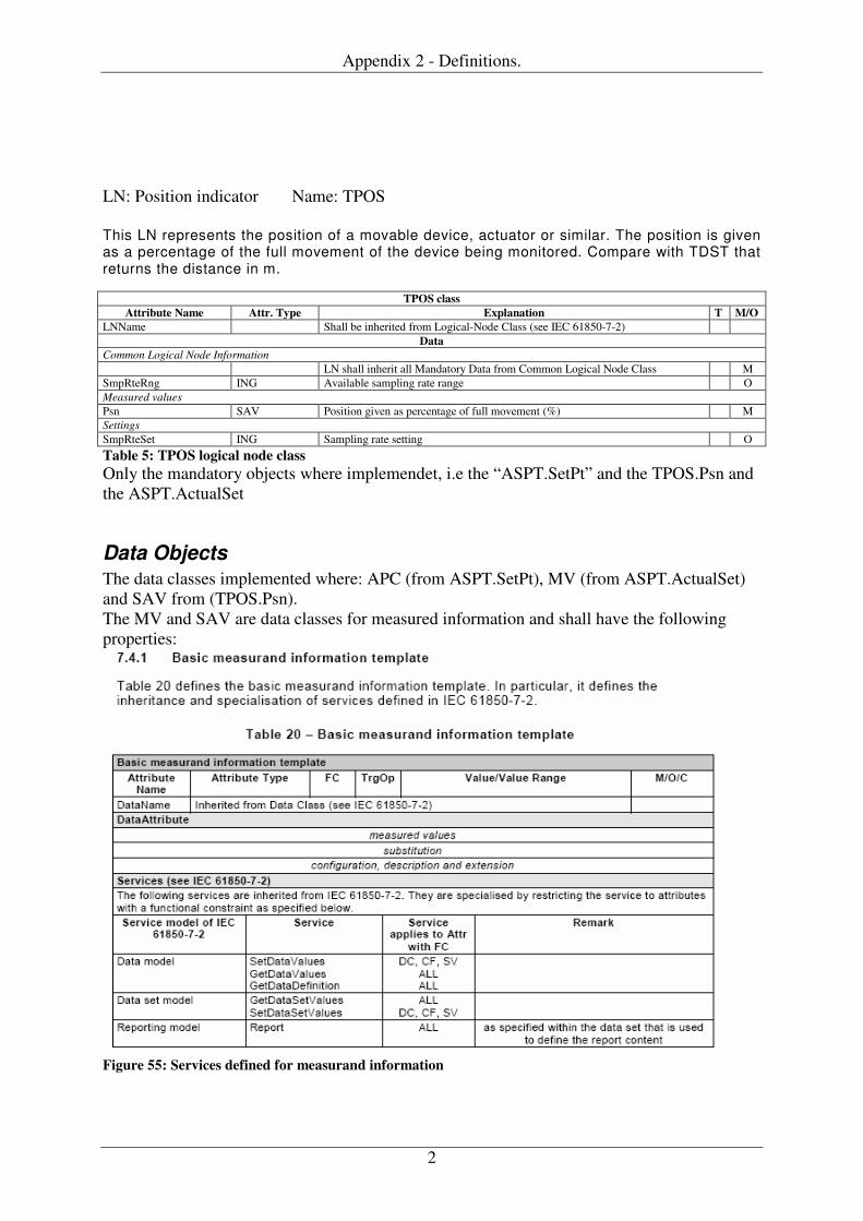
Appendix 2 - Definitions.
2
LN: Position indicator Name: TPOS
This LN represents the position of a movable device, actuator or similar. The position is given as a percentage of the full movement of the device being monitored. Compare with TDST that returns the distance in m.
TPOS class Attribute Name Attr. Type Explanation T M/O
LNName Shall be inherited from Logical-Node Class (see IEC 61850-7-2) Data
Common Logical Node Information LN shall inherit all Mandatory Data from Common Logical Node Class M SmpRteRng ING Available sampling rate range O Measured values Psn SAV Position given as percentage of full movement (%) M Settings SmpRteSet ING Sampling rate setting O Table 5: TPOS logical node class Only the mandatory objects where implemendet, i.e the “ASPT.SetPt” and the TPOS.Psn and the ASPT.ActualSet
Data Objects The data classes implemented where: APC (from ASPT.SetPt), MV (from ASPT.ActualSet) and SAV from (TPOS.Psn). The MV and SAV are data classes for measured information and shall have the following properties:
Figure 55: Services defined for measurand information
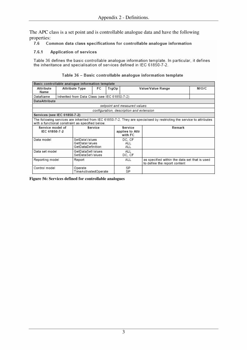
Appendix 2 - Definitions.
3
The APC class is a set point and is controllable analogue data and have the following properties:
Figure 56: Services defined for controllable analogues
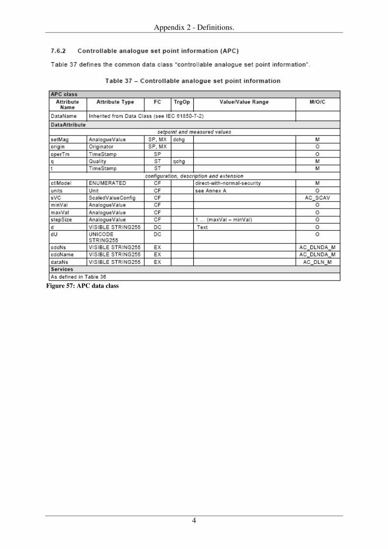
Appendix 2 - Definitions.
4
Figure 57: APC data class
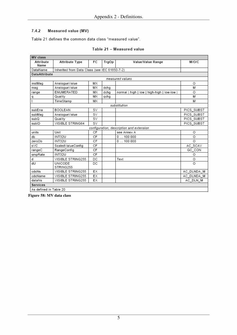
Appendix 2 - Definitions.
5
Figure 58: MV data class
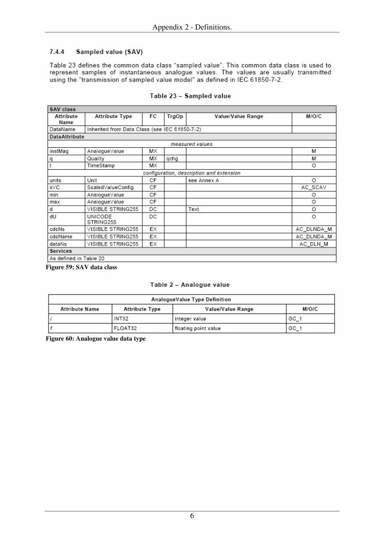
Appendix 2 - Definitions.
6
Figure 59: SAV data class
Figure 60: Analogue value data type