design and implementation of a m2m device with …€¦ · design and implementation of a m2m...
TRANSCRIPT

DESIGN AND IMPLEMENTATION OF A M2M DEVICE
WITH ENERGY HARVESTING AND LOW POWER
CONSUMPTION
A Master's Thesis
Submitted to the Faculty of the
Escola Tècnica d'Enginyeria de Telecomunicació de
Barcelona
Universitat Politècnica de Catalunya
by
Miguel Angel Galarza Osio
In partial fulfilment
of the requirements for the degree of
MASTER IN TELEMATICS ENGINEERING
Advisor: Josep Paradells
Barcelona, April 2014

Page 1
Abstract
Over the last years, M2M networks have experienced a fast expansion. People are
asking for new functionalities and mobile operators, aware of that, have integrated new
services to deal with this demand. The main limitation of M2M devices is related to the
power supply used as it is not always guaranteed an access to a power grid.
To address this problem, it has been designed, constructed and validated an M2M able to
use low-energy sources generation, in this case a Solar Panel. The system was designed
to efficiently manage the power consumption and transmits the information through a
GSM-GPRS network.

Page 2
Acknowledgments:
During the period that lasted this work, several were the persons that helped me and to
which I am very grateful. First, I would like to thank my supervisor Josep Paradells, the
person who gave me the opportunity to do this work and to be part of this research
project. Also a special mention to Laura Herrera who gave me support and provided me
with very useful strategic and scientific advises.
Finally, I would like to thank my family and friends who gave me a very important
emotional support. Without them this work would have been impossible to accomplish.
Thank you very much.

Page 3
Revision history and approval record
Revision Date Purpose
0 15/01/2014 Document creation
1 20/03/2014 Document revision
Written by: Reviewed and approved by:
Date 15/01/2014 Date
Name Miguel Angel Galarza Osio Name
Position Electronic Engineer Position

Page 4
Table of Contents
Abstract ............................................................................................................................ 1
Acknowledgments: ........................................................................................................... 2
Revision history and approval record ................................................................................ 3
List of Figures ................................................................................................................... 6
List of Tables .................................................................................................................... 7
List of Equations ............................................................................................................... 8
1. Introduction ................................................................................................................ 9
2. Background ............................................................................................................. 11
2.1. Mobile Communications ................................................................................... 11
2.1.1. GSM-GPRS ............................................................................................... 12
2.1.2. AT Commands .......................................................................................... 13
2.2. Contiki .............................................................................................................. 15
2.2.1. System ...................................................................................................... 15
2.2.2. Architecture and Libraries .......................................................................... 16
3. Project Requirements .............................................................................................. 17
4. Proposal .................................................................................................................. 18
4.1. Block Diagram .................................................................................................. 19
4.1.1. Power Supply ............................................................................................ 21
4.1.2. GSM-GPRS Module .................................................................................. 23
4.1.3. Micro-Controller ......................................................................................... 23
4.1.4. Sensors ..................................................................................................... 23
5. Modem Selection ..................................................................................................... 25
5.1. JAVA programming for Modem testing ............................................................. 28
5.2. WISMO228 Analysis ......................................................................................... 30
5.3. SARAG350 Analysis ......................................................................................... 38
5.4. Modem Choice ................................................................................................. 41
6. Micro Controller Programming ................................................................................. 43
6.1. MC13224V Functionality................................................................................... 43
6.2. Microcontroller Programming ............................................................................ 46
6.3. Algorithm Design .............................................................................................. 48
6.3.1. Main Program ............................................................................................ 49

Page 5
6.3.2. Transmission Mode ................................................................................... 51
6.3.3. Sleep Mode ............................................................................................... 53
7. Prototype ................................................................................................................. 54
7.1. Prototype Tests ................................................................................................ 54
7.2. Prototype costs ................................................................................................. 58
8. Conclusions ............................................................................................................. 59
9. Future Improvements............................................................................................... 60
10. Programming Code .............................................................................................. 61
10.1. Modem.c ....................................................................................................... 61
10.2. Modem.h ....................................................................................................... 67
11. Bibliography ......................................................................................................... 70
12. Annex .................................................................................................................. 72

Page 6
List of Figures
FIGURE 1. M2M COMMUNICATION SCHEMES ...................................................................... 11
FIGURE 2.AT+CSQ COMMAND RESPONSE IN DBM. ............................................................ 14
FIGURE 3. CONTIKI SCHEDULING CONTEXT ........................................................................ 15
FIGURE 4. INITIAL PROPOSAL DIAGRAM BLOCK .................................................................. 19
FIGURE 5. FINAL BLOCK DIAGRAM SOLUTION ..................................................................... 20
FIGURE 6. 3F AND 5V SUPERCAPACITOR............................................................................ 22
FIGURE 7. PCB FOR WISMO228 EVALUATION ................................................................... 35
FIGURE 8. CURRENT CONSUMPTION DURING A SMS TRANSMISSION IN WISMO228(LEFT) AND
SARAG350(RIGHT) .................................................................................................. 41
FIGURE 9.MC13224V CHIP PAD LAYOUT. ......................................................................... 43
FIGURE 10. MC13224V PINS ............................................................................................ 45
FIGURE 11.ECONOTAG (MC13224V DEVELOPMENT PLATFORM) ......................................... 46
FIGURE 12.TESTING PLATFORM ........................................................................................ 47
FIGURE 13. GLOBAL ALGORITHM ....................................................................................... 48
FIGURE 14.MAIN_PROCESS FLOW CHART.......................................................................... 49
FIGURE 15. FLOW CHART OF TRANSMISSION MODE ........................................................... 51
FIGURE 16. FIRST PROTOTYPE FOR TESTING ..................................................................... 54
FIGURE 17. PROTOTYPE CONSUMPTION USING SARAG350 (3.5V POWER SUPPLY, UNLIMITED
CURRENT) ................................................................................................................. 55
FIGURE 18. SMS SENDING CONSUMPTION IN PROTOTYPE USING SARAG350 (3.5V POWER
SUPPLY, UNLIMITED CURRENT) ................................................................................... 55
FIGURE 19. REGISTRATION TIME OF PROTOTYPE ............................................................... 56
FIGURE 20. SMS TRANSMISSION COST IN MA ..................................................................... 56
FIGURE 21. NETWORK REGISTRATION OF WISMO228 USING THE DEVELOPMENT KIT ........... 74
FIGURE 22.SLEEP AND NORMAL MODE CHANGE IN WISMO228 USING THE DEVELOPMENT KIT
................................................................................................................................ 74
FIGURE 23.SMS TRANSMISSION IN WISMO228 USING THE DEVELOPMENT KIT .................... 75
FIGURE 24.GPRS TRANSMISSION TCP IN WISMO228 USING THE DEVELOPMENT KIT .......... 75
FIGURE 25.GPRS TRANSMISSION UDP IN WISMO228 USING THE DEVELOPMENT KIT.......... 76
FIGURE 26.RECEPTION MODE IN WISMO228 USING THE DEVELOPMENT KIT ........................ 76
FIGURE 27 WISMO228 DEVELOPMENT KIT ....................................................................... 77
FIGURE 28 SARA G350 DEVELOPMENT KIT ...................................................................... 77

Page 7
List of Tables
TABLE 1. GPRS CLASSES ................................................................................................ 13
TABLE 2.EXAMPLES OF AT COMMANDS. ............................................................................. 14
TABLE 3. GPRS MODEM COMPARISON (UNITARY PRICES) ................................................. 26
TABLE 4.WISMO218 AND WISMO228 CURRENT CONSUMPTION (DATASHEET INFORMATION).
................................................................................................................................ 30
TABLE 5.FIRST MEASURES OF WISMO228 POWER CONSUMPTION USING THE DEVELOPMENT
KIT. ........................................................................................................................... 33
TABLE 6.WISMO228 POWER CONSUMPTION IN NORMAL AND SLEEP MODE. ........................ 34
TABLE 7. POWER CONSUMPTION OF WISMO228 IN A CONTROLLED ENVIRONMENT ADJUSTING
BANDS AND SIGNAL LEVELS ....................................................................................... 36
TABLE 8. SARAG350 POWER CONSUMPTION IN SMS AND TCP_SMALL TRANSMISSIONS ..... 39
TABLE 9. WISMO228 AND SARAG350 POWER CONSUMPTION COMPARISON FOR SMS AND
TCP_SMALL TRANSMISSION ...................................................................................... 41
TABLE10. WISMO228 AND SARAG350 COMPARISON (QUANTITY: 1 UNIT) ......................... 42
TABLE 11.MC1322X POWER CONSUMPTION CHARACTERISTICS .......................................... 44
TABLE 12. COSTS OF PROTOTYPES DEPENDING ON THE AMMOUNT ORDERED ...................... 58
TABLE 13. SPECIFICATIONS GSM-GPRS MODEMS I .......................................................... 73
TABLE 14. SPECIFICATIONS GSM-GPRS MODEMS II ......................................................... 73
TABLE 15 POWER CONSUMPTION COMPARISON OF WISMO228 RELATED TO BANDS, PWC
AND GPRS MODE. .................................................................................................... 78
TABLE 16 SARAG350 AND WISMO228 POWER CONSUMPTION VALUES COLLECTED ........... 79

Page 8
List of Equations
EQUATION 1. ENERGY CONSUMPTION FORMULA [JOULES] .................................................. 30
EQUATION 2. POWER CONSUMPTION OF PROTOTYPE TEST ................................................. 57
EQUATION 3. POWER CONSUMPTION OF PROTOTYPE TEST IN TRANSMISSION MODE (AVG.
CASE) ....................................................................................................................... 57
EQUATION 4. POWER CONSUMPTION OF PROTOTYPE TEST IN TRANSMISSION MODE (WORST
CASE)....................................................................................................................... 57

Page 9
1. Introduction
More often, people are interested in a complete knowledge of their surrounding
environment and every day new ubiquitous computing solutions are needed to deal with
client requirements. Many private and public organizations have been aware of this, and
are demanding new M2M services in order to fulfill the necessities of this expanding
market known as the internet of things.
Internet of things is considered a worthy market for deploying new solutions and
products. M2M Services are being integrated into numerous sectors as Building, Industry,
Health, Transport, Energy, and Safety. All these services have a common purpose:
offering self-managed systems capable of collecting data from different sources and
taking decisions according to predefined requirements.
There exist several mechanisms and protocols used for deploying M2M services.
Wireless Sensor Networks base their communication in a connectivity grid where nodes
collect data and exchange information between them using wireless communication
protocols. Nevertheless, as a large number of applications are intended to be
commercialized very quickly, several M2M solutions implement another approach: use a
completely deployed and tested network for connectivity, Mobile Networks.
M2M solutions based on Mobile Networks are growing fast thanks to the already
deployed infrastructure, security, stability and scalability. The usage of Mobile Networks
for designing a M2M solution application will be the main focus of this work. There will be
considered the advantages and drawbacks related to the use of different Mobile
Networks technologies as 2G, 3G and 4G.
Several mobile operators have noticed this expanding market and have started to create
new M2M oriented services to satisfy the requirements of this kind of networks at lower
rate costs. Also, as more applications are integrating Mobile Networks as M2M solutions,
prices of mobile wireless modules have started to decrease allowing a bigger scalability
and deployment of more complete solutions.
The principal aims of a M2M solution are to guarantee scalability, reliability, availability,
low cost and low maintenance. The three first characteristics depends mostly on the type
of network implemented, and as that have been already defined, the goal in this project
will be to improve the features related to low cost and low maintenance.
In order to achieve a low cost solution, there must be compared different providers in
order to minimize the electronic component cost. To assure a low maintenance solution is
also needed to guarantee a self-sustaining source of energy. Instead of using batteries
which needs periodic replacement, the goal is to implement a low maintenance power
supply capable of working with harvesting energy sources.
Although the difficulties related to the use of this kind of energy to power mobile and
ubiquitous systems, there are clear advantages related to maintenance costs and evident
environmental benefits. Certainly, harvesting sources will not be able to guarantee a
constant operation but this is neither the goal. The solution is oriented to applications with
certain transmission delay tolerance.

Page 10
To summarize, the project is based in the design of a low cost device capable of
collecting data from different sensors and operating with harvesting energy sources. The
communication interface consists in a Mobile Modem for connecting to an already
deployed Mobile Network. The device is also intended to have another wireless interface
as an 802.15.4 radio.
The document is structured as follows: In Section II it is presented a background
containing information required to understand the development of the project, Sections III
and IV follows up by summarizing projects requirements and describing the project
proposal. Section V and Section VI explain the procedure followed to select the Modem
and programming the microcontroller. Finally, Section VII, VIII and IX show the prototype
test, conclusions and some future improvements.

Page 11
2. Background
The project is based in the design of a M2M Mobile device; therefore, it will be presented
an overview of actual Mobile architectures, their features and explanations of its benefits
and drawbacks. It will also be explained an operating system dedicated to the
development of applications for low-power microcontrollers. Finally there are shown some
set of commands used to configure and operate most of the modem nowadays (AT
commands).
2.1. Mobile Communications
A M2M communication can be established using wired or wireless interfaces; each one
has its advantages and disadvantages, however nowadays the maximum potential of a
M2M system is reached using a wireless connection. Wireless connectivity offers a big
flexibility and mobility, this work has it basis on using wireless connectivity, especially
Mobile Networks for M2M communication.
M2M technologies uses, mainly, the data mobile structure so mobile packet gateways like
GGSNs and HLRs are two of the most critical network elements relative to M2M service
deliver in the Mobile Network. These gateways provide security, Quality of Service (QoS)
enforcement, and interaction with charging and billing systems for mobile data service.
Due to the difference on the management for M2M devices, there is a trend towards
dedicated M2M network infrastructure deployment (GGSNs and HLRs only for the M2M
management) specifically for the provisioning of M2M services. It has been proposed
(some versions are actually in production and in use) changes in the SIM for M2M
devices, as integrated circuits with embedded SIMs in the electronic circuit: C-SIM
(componentSIM), E-SIM (electronic SIM), embedded SIM, chip on SIM.
The deployment of large M2M applications has lead Mobile Operators to design special
and cheaper rates for M2M solutions, for example allow them to transfer data in
scheduled period during the night when there is a lower traffic usage of the network. Also,
generally the bandwidths requirements for most M2M projects are low.
Figure 1 shows different approaches for transmitting data in a M2M project, in some case
it is preferable to use SMS or CSD for communicating with a central instead of a packet
data connection.
Figure 1. M2M Communication Schemes

Page 12
Services using SMS offer a high reliability and integrity, have a good degree of encryption
and offer a bigger coverage transmitting at higher power than packet data. The
inconvenient is the small payload, but is generally enough for most M2M applications
(160 ASCII Characters).
In relation to packet data connections, there are some problems related to the dynamism
of IP addresses for M2M devices. As these devices have dynamic IP address, it can be
difficult to send them information if the socket was not previously created and maintained,
some techniques that can be implemented are the creation of a VPN between the M2M
device and the customer firewall, or the use of DNSs. In both cases the socket
establishment will require more time than using public IPs.
There are several mobile communication technologies, 2G and 3G are useful in this kind
of applications, on the other hand, 4G is a new technology that even when it offers higher
transmission rates, it is a recently deployed system and do not offers the same coverage
that a fully deployed 2.5G or 3G could. Moreover, WSN solutions do not require that great
amount of bandwidth that 4G can provide.
3G technology offers a bigger transmission rate (up to 2Mbps in a theoretical UMTS) in
comparison to 2G technology (up to 171kbps in a theoretical GPRS), nevertheless the
energy consumption for transmitting a small amount of data in 3G is higher than in 2G,
also modems with 3G capability are more expensive.
The energy consumed by a modem using 2G or 3G depends on the amount of time the
modem remains in idle state and the amount of data is transmitted. In idle state a modem
using 2G consumes in average a 30% less than a 3G modem and in transmission mode
the consumption using 2G is 40% less than using 3G but the transmission rate is also
significantly inferior.
In conclusion, if it is needed to transmit a larger amount of data is preferred to employ
3G, on the other hand, if the application will remain in idle mode most of the time and
transmit a little amount of data is preferred to employ 2G. The consumption values were
obtained from the sources referenced in the bibliography.
2.1.1. GSM-GPRS
Over the time the GSM network evolved to allow data transmission. The first version that
allowed data transmission was commercialized as GPRS and the second one with higher
speed rates as EDGE. GPRS is a highly tested and reliable architecture very useful in
applications with low transmission requirements.
The average current consumption depends on the GPRS class used by the module;
classes define the number of time slots used for downloading and uploading. The most
common GPRS classes are Class 8, Class 10 and Class 12. Higher Class Numbers
correspond to a great amount of timeslots used for downloading and then faster transfer
rates and higher current consumption. Table 1 shows the different GPRS classes, none
all devices are capable of supporting all classes.

Page 13
Multislot Class
Downlink TS
Uplink TS
Active TS
1 1 1 2
2 2 1 3
3 2 2 3
4 3 1 4
5 2 2 4
6 3 2 4
7 3 3 4
8 4 1 5
9 3 2 5
10 4 2 5
11 4 3 5
12 4 4 5
30 5 1 6
31 5 2 6
32 5 3 6
33 5 4 6
34 5 5 6
Table 1. GPRS Classes
2.1.2. AT Commands
AT commands, initially known as Hayes commands were created by Hayes Company for
programming their modems. This set of commands later became an ITU standard used
for modem configuration and execution of operations as dialing, sending SMS, or
registering to the network. The standard supports a limited set of commands that each
vendor is able to increase in order to offer more functionality.
AT commands are presented in the syntaxes: AT+command, where command is the
required operation to be executed. Some of the more important and useful commands
are presented in Table 2. Each command has one or a set of possible responses, thanks
to this values it is possible to program easily modems trough the UART port.

Page 14
AT command Function
AT Check device availability
AT+CPIN Check PIN status or introduce password
AT+CREG? Check network registration
AT+CREG=2 Enables notification of LAC and CID
AT+CSQ Check Signal Level *View Figure 2.AT+CSQ
Command Response in dbm.
AT+CMGS=”number” Send SMS
AT+CMGF=1 Enables the SMS text mode
AT+COPS? Shows current operator
ATE0 ATE1 Deactivate/Activate Echo
Table 2.Examples of AT commands.
In the Annex Section it is presented the list of commands used in the programming of the
modems used. In relation to registration and SMS transmission procedures, the set of
command is the same, on the other hand, for transmitting data through TCP or UDP each
modem has it set of proprietary commands. Through some AT commands it can be
adjusted the size of the payload for UDP transmission and for TCP it can be adjusted
parameters as the MSS, initial TCP windows sizes and minimum fragmentation timeout.
Figure 2 shows the relation between the AT+CSQ response of the modem and the
current level of signal power received by the antenna in dbm. This value is useful for
determining the link QoS; for values lower than 11 the reception is not optimal and there
could be problems in the transmission, for example higher delays or not successfully
transmissions.
Figure 2.AT+CSQ Command Response in dbm.

Page 15
2.2. Contiki
2.2.1. System
Contiki OS is an open source operative system designed for low demanding applications.
It is usually dedicated to embedded systems and WSN deployments due to the small
requirements of processor and RAM. The operative system implements protothreads and
interruptions as a mechanism for concurrent programming.
There are other common operating systems designed for this kind of network as Tiny OS,
Mantis and SOS, nevertheless Contiki OS offers advantages as TCP/IPv4-v6 stack,
programming in C language and a large number of libraries already designed. The
Contiki kernel is based on events interruptions and lightweight stackless threads called
protothreads, which are functions similar to threads but with a lower memory overhead.
In Contiki, single protothreads are known as processes. A process is a single piece of
code executed by the system, these processes can be executed periodically or being
activated by an external interruption, timers or other events.
As it is presented in Figure 3, Contiki code runs in cooperative or preemptive context. In
cooperative context each process is executed sequentially after the other, on the other
hand, preemptive context stops for a moment the cooperative context to execute another
process and when it finishes, the cooperative context is resumed. All processes run in
cooperative context, but by the use of timers or other interruptions which runs in a
preemptive, it is possible to get a similar functionality to multithreading.
Figure 3. Contiki Scheduling Context

Page 16
2.2.2. Architecture and Libraries
Protothreads statements used in Contiki for programming are similar to traditional ones,
PROCESS_BEGIN() and PROCESS_END are the declarations used for defining the start
and finish of processes, PROCESS_WAIT_() is a declaration used to wait for a special
event or condition (Timers or Flags). PROCESS_PAUSE() is intended to led resources to
other processes, useful for running several processes as they were running
simultaneously.
In Contiki there are synchronous events, which are delivered to the kernel immediately,
and asynchronous events that when posted are added to the kernel’s event queue and
delivered later. Processes can be started and stopped from other processes through
process_start() and process_exit(), Contiki also provides a mechanism for auto starting
processes automatically when the systems is booted.
Contiki OS provides a large set of libraries for programming in C language; there are also
a great amount of other libraries that can be used with different CPU platforms. The more
common libraries used are the dedicated to process and timers. These libraries are
designed to manage executions and interruptions of processes.
Other libraries, allow configuring and managing communication interfaces, ADC and
other digital inputs or outputs. These libraries depend on the CPU platform used, and link
different memory registers to simpler names in order to create a more understandable
code.
Page 17
3. Project Requirements
The project aims the development of a M2M device capable of monitoring and controlling
external variables, it must also transmit updated values to a centralized server using a
Mobile Network. In order to create a competitive product, the solution must accomplish
certain features in terms of price, energy consumption and size.
The final price will depend mostly on the number of devices assembled since the price
per unit of each component decreases significantly when the demanded order increases.
The electronic components associated with higher costs are the communication interface,
the energy storage device and the energy power supply (in our case a solar panel). There
is not an upper bound requirement in relation to the cost, but it must be the smaller
possible.
Energy efficiency is also a critical issue since the Module should be able to be powered
by harvesting sources technologies (solar, piezoelectric, vibration, thermoelectric,
acoustic…). In the startup of the project it will be used a Solar Panel that must be capable
of obtaining energy in an indoor environment, with low luminosity or artificial light. In
future models it can be added another harvesting energy source.
The device should have a small size and as it must incorporate a solar panel it is
proposed a maximum of 40x60x30mm. The containing box must provide a good shelter
to deal with environmental conditions as humidity, heat and possible impacts.
As the final use of the solution is not given, the device should be easy to reprogram and
capable of being remotely connected to an IEEE 802.15.4 radio interface. It also must
have external connections to add new sensors or actuators.
The rate of updating variable values is not fixed, so it is possible to manage the
transmission according to energy levels. Even when it is not required, the suggestion is to
execute at least one transmission of storage values per day. In the worst case, values
could be saved in memory until the energy level could allow complete transmission of all
values.
In relation to the communication, it is required the operation with a certain operator of a
Mobile Network (Operator Z). The device should be able to send the updated values
through different mechanisms as SMSs or data packets. The most suitable solution will
depend on the energy available and transmission rate needed.

Page 18
4. Proposal
According to the requirements, the top priorities of the solution are to guarantee power
efficiency and low cost. The idea is to power the device using harvesting sources, in this
case it will be used a solar panel capable of work in indoors with a luminosity very limited;
on the future the power source could be replaced by other harvesting sources.
My work was based in the selection and testing of the communication Modem, and the
programming of the code in the microcontroller, nevertheless it will be provided a global
explanation of the hardware developed by the rest of the team in order to understand the
general capabilities of the design.
There are several aspects that must be considered in order to select the right modem; the
first one is related to the network technology (2G, 3G or 4G).In Section 2.1 there were
compared the benefits and drawbacks of using GSM-GPRS networks over 3G networks
for these kind of devices.
Based on the energy consumption requirements and the limited power generation of a
harvesting source, it is preferred to use a GSM-GPRS network for this project. GSM-
GPRS does not only provide lower consumption values but also assures an enough
transmission rate for sending the required data. Another advantage is the lower price of a
GMS-GPRS Modem in comparison to a UMTS Modem.
The next aspect to consider is related to the microcontroller programming, it must be
assured an energy efficient execution of processes. The microcontroller to be used must
have low power consumption on Sleep Mode. It should also contain communication
interfaces like UART to integrate the modem, ADCs, Digital Inputs and Outputs, and an
802.15.4 radio interface.
With the idea of maximizing the energy collected, additional electronic components
should have the lower possible current leaks. The goal is to completely disconnect
unused blocks when there are not needed and to incorporate a high impedance at the
output of the storage device in sleeping mode.
Harvesting sources present several problems due to the low energy generation and
variable cycles of charging and discharging. That is why the energy storage component
must be tolerant to these conditions and guarantee a long life time.
The M2M device initially proposed was composed by the following components:
- Solar panel (Capable of working in indoors and outdoors).
- Energy charger device
- Energy booster device
- Storage device
- MCU with IEEE 802.15.4 support
- GSM/GPRS module
Page 19
As it will be explained in Section 4.1, the final proposal does incorporate neither the
energy charger device nor the energy booster device. Furthermore, it will be explained in
more details each component, its functionality and integration in the final solution. In
section 4.1.1is explained the selection of the energy storage device, in this case a
supercapacitor.
4.1. Block Diagram
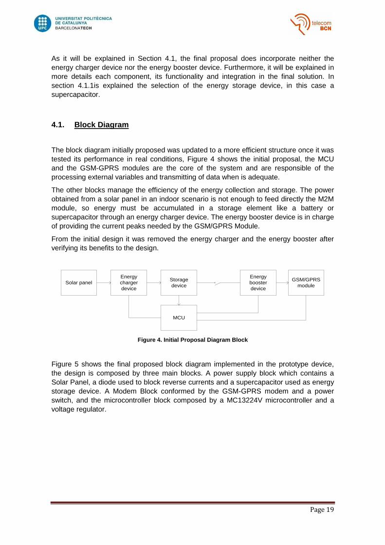
The block diagram initially proposed was updated to a more efficient structure once it was
tested its performance in real conditions, Figure 4 shows the initial proposal, the MCU
and the GSM-GPRS modules are the core of the system and are responsible of the
processing external variables and transmitting of data when is adequate.
The other blocks manage the efficiency of the energy collection and storage. The power
obtained from a solar panel in an indoor scenario is not enough to feed directly the M2M
module, so energy must be accumulated in a storage element like a battery or
supercapacitor through an energy charger device. The energy booster device is in charge
of providing the current peaks needed by the GSM/GPRS Module.
From the initial design it was removed the energy charger and the energy booster after
verifying its benefits to the design.
Figure 4. Initial Proposal Diagram Block
Figure 5 shows the final proposed block diagram implemented in the prototype device,
the design is composed by three main blocks. A power supply block which contains a
Solar Panel, a diode used to block reverse currents and a supercapacitor used as energy
storage device. A Modem Block conformed by the GSM-GPRS modem and a power
switch, and the microcontroller block composed by a MC13224V microcontroller and a
voltage regulator.
Solar panel
Energy
charger
device
Storage
device
Energy
booster
device
GSM/GPRS
module
MCU

Page 20
Figure 5. Final Block Diagram Solution
The microcontroller used in the final design was the MC13224V from Freescale; it
accomplishes all the requirements; low cost, power efficiency and integration of all the
interfaces needed for developing the application. In addition, it was considerable
documented and was highly recommended. More details about the Microcontroller are
explained in Section 4.1.3.
The Modem implemented in the final design was a U-blox GSM-GPRS Modem (SARA
G350). This modem was selected by its functionality, energy performance and relative
low cost in comparison to others modems evaluated. The selection process of Modem is
explained in section 5.
This hardware design has been proved to work with two GSM/GPRS modules
(WISMO228 from Wavecom and SARAG350 from U-blox). As each Modem has different
power requirements the design must be evaluated in case of integrating another module,
specially the Power Supply Block. The integration Modem-Microcontroller tends to be
easy thanks to an UART communication interface which most of the modems have.
In Figure 5, there are also presented other electronic components, one is located in the
Modem Block (TPS27082L) and is responsible of switching on and off the modem. This
switch is controlled by a digital output of the microcontroller with the idea of disconnecting
the modem completely of the power grid when not used to avoid any current leak. When
the switch is on, the incoming voltage of the supercapacitor goes directly to the Modem
input.
The other component is located in the microcontroller Block (TPS62081) and it is a low
consumption regulator that set an output of 1.8V necessary for the operation of the
microcontroller. This regulator has two operation modes, Snooze Mode when it only
consumes 6.5µA and provides up to 2mA, and Normal mode when it consumes 30µA and
provide up to 2.8A. This regulator is also controlled by a digital output of the
microcontroller.

Page 21
4.1.1. Power Supply
As energy source it is used low intensity light radiation, as indoor luminosity or artificial
light. Solar harvesting is a method of generating electrical power by converting solar
radiation into direct current electricity by the photovoltaic effect. The output of a
photovoltaic cell is a product of the area, the efficiency, and the solar energy radiation.
Operation of solar panels in indoor environments presents limited energy characteristics.
Above there are presented the corresponding restrictions:
- Lighting power density of 10-4 W/cm2
- Typical solar panel efficiency of 17%
Thus, for a solar panel of dimensions 40x60mm, the output power provided will be
approx.:
40x60mm2* 10-4 W/cm2 * 17% = 400µW
This energy generation rate is not enough to assure a constant operation of the modem,
therefore, it is required to implement a duty cycle that alternates between operational
mode and off mode. Also some kind of efficient storage device is needed in order to
collect the maximum amount of energy possible.
Taking into account the irregular charging cycles of harvesting sources, it is needed a
storage device able to draw on all the energy collected, minimize current leakage and
provide a long lifetime duration. It also should be capable of charging quickly and be
resistant to a large number of charging and discharging cycles. Best candidates are
batteries and supercapacitors.
Batteries are great storage devices capable of providing large amount of energy, the
problems with these devices are the short lifetime and the long duration of the charging
process, on the other hand, supercapacitors have less energy capacity but have a
greater power density, supercapacitors also guarantee many more cycles of charging and
discharging.
In comparison, a Li-ion battery can carry on between 500 and 1000 charging cycles
before its capacity get reduced to 50%1 and a supercapacitor up to 100.000, as the
device is intended to require the minimum maintenance, supercapacitors are the best
choice. Moreover, supercapacitors are cheaper than batteries (2€-4€ depending on the
amount ordered and its capacity).2
The problem with a supercapacitor is related to the linear voltage variation depending on
the energy collected, so even when they could have enough energy to perform tasks, it is
not useful due to the operational voltage range of the devices connected to them.
1http://batteryuniversity.com/learn/article/how_to_prolong_lithium_based_batteries
2http://es.rs-online.com/

Page 22
Figure 6. 3F and 5V supercapacitor
The solar panel output is connected directly to the energy charger device using a diode
for controlling reverse currents. It was selected a supercapacitor capable to fulfill the
following characteristics:
- To allow input voltage from solar panel of hundreds of mV
- Output voltage comprised between 2 – 4.5V (suitable for MCU and GSM/GPRS
module supply)
- Low shutdown and leakage current
- Low price
The capacitance of the supercapacitor must be chosen according to the power
requirements and power supply sources. After several tests, it was selected a
supercapacitor of 3F and 5V (Figure 6), this device establishes a good compromise
between collection and supply of energy per day according to the designed application.
There are presented more details and results in Section 7.
After several tests, it was obtained that a 3F supercapacitor could be charged in less than
2 hours with direct sunlight and in about 8 hours with artificial or indirect light. If it is
assumed a Voltage of 5V, 3F represents a total amount of energy of:
E=1
2𝐶. 𝑉2 =
1
23𝐹 × (5)2= 37.5Joules.
Nevertheless not all this energy is useful because the operational range of the
GSM/GPRS Modem SARAG350 is from 3.2V to 4.5V. The total amount of energy
capable to provide the supercapacitor in the range needed for the operation of the
modem would be:
𝑬 =1
2𝐶. 𝑉𝑚𝑎𝑥2 −
1
2𝐶. 𝑉𝑚𝑖𝑛2 =
1
2× 3𝐹 × 4,5𝑉2 −
1
2× 3𝐹 × 3,2𝑉2 = 15,02𝐽𝑜𝑢𝑙𝑒𝑠
As the system is conceived to work in both outdoor and indoor conditions it was initially
proposed the implementation of an energy charger with the goal of improving the
charging performance. This charging device could help to use more efficiently the energy
collected and accelerate the charging process. After several tests it was proved that it did
not give any perceptible benefit ant it was removed from the design.
The other component initially proposed and later on eliminated was an energy booster, its
intention was to maximize the usage of stored energy and provide the GSM/GPRS
Module all the current and peaks needed for working effectively. After some tests it was
decided that it was not needed, the supercapacitor was able to overcome the module
consumption.

Page 23
4.1.2. GSM-GPRS Module
The Mobile communication capacity of the node will be provided by a GSM/GPRS
modem. This module should fulfill the following characteristics:
- GSM/GPRS network access and SMS service.
- USSD (Unstructured Supplementary Service Data) capability.
- Support of Internet protocols.
- Temperature of Operation from -25C to +60C.
- Low energy consumption.
- Reduced size of maximum 40x40x5mm.
Once the previous characteristics are assured, the main elements taken into account in
the selective process are the energy consumption (operational voltage and current
consumption) and the price of the module. There are some additional but not mandatory
characteristics that could give more value to the modules as GPS hardware integration
and quad-band support. The selection patterns are detailed in Section 5.
4.1.3. Micro-Controller
The microcontroller unit is the core unit of the device. It will be always active and will be
responsible of collecting external variables, controlling the duty cycle for saving energy,
transmitting data through the GSM/GPRS module and controlling the operational logic.
The microcontroller is programmed under a Contiki Operative System and using the C
programming code language. In Section 6, it is explained the programming and
functionality of the microcontroller used in this project (MC13224V).
4.1.4. Sensors
The microcontroller contains ADC channels and KBI inputs that can be used for collecting
values of transducers as temperature sensor, CO2 sensor, alarms detectors, luminosity
sensors. It could be also incorporated a GPS unit in order to transmit location information.
As in the first proposal is not considered the integration of a GPS unit, an alternative
solution could be to obtain an approximated location using the cell ID and the Location
Area Code (LAC). The Cell ID value is obtained when the modem registers to the
network; therefore it is not needed to waste extra energy obtaining it. This value can be
sent together with other data and the server will be the responsible of getting information
about the location and range of that cell ID. Some tests were executed in the UPC and it
was achieved an accuracy of 300 meters.
In some cases, it is easy to integrate a GPS unit to the device, if it is used a SARAG350
modem; there are some U-blox GPS that can be incorporated directly through I2C and
managed directly using AT commands. In other cases, the GPS must be connected to
the microcontroller and has to be managed independently.

Page 24
As some sensors consume extra energy when there are powered and the goal is to save
energy, the integration of sensor requires an additional hardware and software
programming that disconnect those sensors of the power grid when they are not needed.
This technique is applied to monitor the battery level, it is used a switch (Scap Switch)
that connects the supercapacitor to the voltage divisor (resistance array) only when it is
needed to read the current value.

Page 25
5. Modem Selection
The first phase of the project consisted in finding different GSM-GPRS modules suitable
for the application specified. After filtering by characteristics, there were acquired the
modules with the best features in order to verify its performance under real
circumstances. After that, Modems were tested and depending on the results it was taken
the decision of which module was the most suitable for the required service.
The first selection pattern was based on selecting only those modules which had certain
features:
- Network Access via GSM / GPRS and SMS.
- USSD (Unstructured Supplementary Service Data) interoperability.
- Capability of managing TCP and UDP.
- Operating temperature range between -25 ˚C to 60˚C.
- Low power consumption devices.
- Size less than 40X40X5 mm.
After the first filter, the priority features that were taken into account were:
- Power consumption in:
o Off Mode.
o Idle Mode.
o GPRS Mode (Class10).
- Cost.
- Supply Voltage.
In the third selection pattern it was considered other non-essential features that could add
some value to the module, such as:
- Quad Band/ Dual Band.
- Number of GPIO.
- Jamming Detection.
- GPS Inside.
- SIM interface integrated.
Using the comparison patterns described before there were analyzed modules from
several companies specialized in M2M design like U-blox, CINTERION, TELIT,
SAGEMCOM, uMICRONICS and WAVECOM. Finally it was obtained a short list of the
most appropriate modules for the application. Table 3 shows a brief comparison of the
selected modules to be used. In the Annex Section there is a more complete comparative
table showing more features related to different modules not presented in Table 3.
For the analysis, it was specially considered the voltage operational range, the cost and
the power consumption in GPRS Mode. As the goal is to guarantee maximum energy
efficiency, the Modem will be turned off most of the time. Also, in order to avoid the small
current consumption associated to the “Off Mode” the Modem will be completely
disconnected from the power supply block when there is no needed to perform
transmissions.

Page 26
Brand
(Name)
Power Supply
(V)
Power Consumption Off Mode
(uA)
Power Consumption Idle (mA)
Power Consumption GPRS (mA)
Cost (Euros/Unit)
GPS
Inside
TELIT
(GE-865 DUAL V3)
3.2 a 4.5
2 1.1 DRX9 330 class10 47 No
WAVECOM (WISMO21
8)
3.2 a 4.8
36 1.22 DRX9 366 class10 49.9 No
WAVECOM (WISMO22
8)
3.2 a 4.8
40 1.3 DRX9 371 class10 54.75 No
Ublox
(SARAG350)
3 a 4.5 60 1 DRX9 240 class10 25 No
TELIT
(864-GPS)
3.2 a 4.5
62 1.5 DRX9 420 class10 56 Yes
TELIT
(863-GPS)
3.2 a 4.5
26 2.6 370 class10 100 Yes
Table 3. GPRS Modem Comparison (Unitary Prices)
As the device is intended to be used for transmissions only, the power consumption in
Idle Mode is not going to be considered. Appreciating the Power Consumption in GPRS
presented in Table 3, the best choices are SARAG350, TELIT-GE865 and WISMO218.
TELIT-GE-865 offers a good performance, however due to a low numbers of providers its
integration in the study was delayed until determining the supply capacity of providers.
With respect to the GPS module, it is important to determine which of both solutions
(external or integrated module) performs better in terms of energy consumption. The
GSM/GPRS module needs to be active for the operation of its corresponding embedded
GPS module. On the other hand, an external GPS device can be controlled by the MCU,
thus maintaining GSM/GPRS device off. In a future GPS integration, both solutions have
to be studied in order to resolve which one is more energy efficient.
Concerning the modules with integrated GPS, we choose as possible candidates the
863-GPS and 864-GPS from TELIT, both offering quad band capacity. As best choice, it
is selected the TELIT (864-GPS), this module has a lower cost and provides and idle
Mode consumption current much lower compared to TELIT (863 -GPS).
Even when the transmission consumption is higher for the 864-GPS, most of the time the
device will be in reception and thus is more convenient. Both, TELIT 864-GPS and TELIT
863-GPS have similar power consumption due to the GPS (including the antenna) of
about 55mA, this data must be certified in a real scenario.

Page 27
We were able to execute some tests on an external GPS (LEA-6H) from U-blox, which
could be integrated easily to the SARAG350. It performed well, but the main drawback is
that it is quite expensive. As it was not possible to test a GPS inside modules it was not
possible to define which solution (External or internal GPS) is more convenient.
Finally, we could obtain a SARAG350 sample and we were able to realize test over it.
There were executed the same tests done with the WISMO228 in order to compare them
properly. Section 5 describes each modem and what features leads us to decide which to
use in this project.
The first phase of the project proposed only a general and non-conclusive decision of the
definitive module. If during practical analysis in phase two, there were found any other
module with improved performance, it could be incorporated into the analysis while this
did not affect the work schedule.
There were selected as candidates two modules, the SARAG350 from U-blox and the
WISMO218 from Wavecom. Initially there were problems finding the SARAG350 because
it was a recently launched product (progress of being certified) and was difficult to obtain,
therefore, first test were executed on the WISMO218.
Prices references were obtained3 from different providers, in all cases was chosen the
lower price found among all providers. The price decreases when the amount of devices
requested increase, Table 3 shows the unitary price for each Modem.
WAVECOM (WISMO218) presents an appropriated cost compared to the rest and similar
consumption characteristics, also it is a relatively fast to program module. Later on, it was
evaluated the WISMO228 and verified than it provided better benefits related to its
firmware and a more extensive list of proprietary AT commands that could help us to
develop the project.
WISMO228 was supposed to have consumption bigger than its predecessor WISMO218,
but in our test we did not appreciate that difference, so we took as new best candidate
the WISMO228. This modem is also Quad Band compliant, which is worthy in case an
application needs to be installed in countries that use different GSM bands.
Practical tests of phase two consisted on verifying the real consumption values under
different scenarios: Idle Mode, Off Mode or GPRS transmission. The main goal was to
determine if the dimensioning of the power supply was appropriated. Also it was tested
the receiver sensitivity and the processing time required to run processes as SMS and
TCP/UDP transmissions.
3Prices references, (December 2013):
http://es.rs-online.com, http://www.u-blox.com, http://www.aliexpress.com, http://es.farnell.com/, http://www.telit.com/, http://www.tme.eu/.

Page 28
5.1. JAVA programming for Modem testing
In order to evaluate the real performance of the Modem, it was written a program in Java
(Eclipse) that automatically transmits sequences of AT commands from the PC to the
Modem through the Serial Port. Each AT command is associated to a set of responses;
analyzing these responses allowed to determine if the command was processed
successfully.
There were created the following tasks for testing the Modem:
- Registration: Consisted in turning on the device and waiting registration to the
network.
- SMS Transmission: Consisted in turning on the device, waiting registration to the
network, transmission of a SMS, waiting of the SMS receipt sent and turning off
the device.
- TCP or UDP Transmission: Consisted in turning on the device, waiting
registration to the network, connection to a TCP/UDP socket server, performing of
the transmission, waiting the receipt of data sent and turning off the device.
- SMS Reception: Consisted in turning on the device, waiting registration to the
network, waiting a SMS reception and turning off the device.
These tasks were adapted and executed in both, the WISMO228 and SARAG350 to
compare the energy consumption associated to each one. Using a power analyzer, it was
possible to determine the current consumption during all the process; thanks to this data
and the voltage of the power supply was possible to obtain the total energy consumed,
the analysis of this consumption will be explained in next sections.
Eclipse was installed in a Windows Operating System (Windows 7) and the java library
used for the configuration and sending of commands trough the serial port was Giovynet.
Giovynet is an open source library for Windows that allows an easy management and
configuration of Serial Port and buffers. The java code used is presented in the Annex
Section.
Modem and PC UART ports were configured at the maximum speed possible to manage
and the connection parameters configured as it is presented:
Bit rate: 115200bps.
Format: 8 bits, 1 stop bit.
Parity: none.
Flow control: hardware.
Delay Write: 0ms.
The TCP/UDP server employed to receive the data was also programmed in Eclipse and
a Windows environment; the Server had a fixed public IP and it was not necessary to use
a DNS. In the final deployment it has to be considered that using DNSs could increment
the time of establishing the connection.

Page 29
The exchange of data through SMSs is simpler than through TCP/UDP connections.
When it is send a SMS, the mobile operator is the responsible of storing and transmitting
the SMS once the destination is available, on the other hand for TCP/UDP connections it
is needed to establish a socket for transmitting the data.
It must be taken into account that the Mobile Network assigns dynamic IP addresses to
subscribers in the network, if it is not implemented a DNS solution the server will not be
able of identifying the IP address of the Modem until it creates a socket and identify itself.
It also has to be considered that the modem will be sleeping most of the time and it will
have irregular wake up periods, for that reason, the server has no way to determine when
it is awake until the node announce itself.
There is a difference between the management of data using TCP and UDP; in TCP it is
not possible to define datagrams, just maximum buffer sizes and timeout periods for
sending data. On the other hand UDP allows defining datagrams of a predetermined size.
Data can be sent through UDP using two different modes, Continuous transparent mode
where there is no special meaning associated to [DLE]/[ETX] characters, and Continuous
mode where a [ETX] character is considered as an end of data. When an [ETX] character
is sent on the UART, the TCP socket is shut down and the peer side is informed of this
shutdown with the indication [ETX].
It was found that the AT command used to turn off the modem generate a current peak
and consumes some energy. Even when it is recommended to properly turn off the
device, there are not immediate consequences and the modem could be turned off
cutting the power supply, in this way reducing the power consumption.

Page 30
5.2. WISMO228 Analysis
Initially, we proceeded to the WISMO228 GSM/GPRS device validation through the
evaluation on its development kit. According to the datasheet (Table 4) the WISMO228
module presents a slightly higher consumption with respect to WISMO218, but after
some tests this difference was not appreciated so we conclude to use WISMO228 due to
a best firmware release and a greater number of AT Proprietary commands dedicated to
TCP and UDP connections.
Device WISMO218 WISMO228
Consumption Idle Mode (mA) 1.3 1.22
Consumption GPRS Mode Peak
(mA) 366 371
Table 4.WISMO218 and WISMO228 Current Consumption (Datasheet Information).
The GSM/GPRS module validation procedure consists in obtaining measures of the
energy in Joules consumed by the device when it executes different tasks:
- Registration: Procedure of registering the device to the GSM Network.
- SMS Transmission: Registration and SMS transmission.
- SMS Reception: Registration and waiting until device receives a message.
- Call execution: Registration, Call execution and Hang up after 10sec of tone
ringing.
- GPRS Data Transmission using a UDP Socket: Registration and Transmission of
one UDP packet with ASCII characters. It is started the IP Stack meanwhile the
device is registering to the network to save time.
- GPRS Data Transmission using a TCP Socket. Registration and transmission of
several TCP packets containing. It is started the IP Stack meanwhile the device is
registering to the network to save time.
AT commands are sent automatically to the GSM/GPRS module trough the serial port
RS232 using the developed Java program. It is important to assure a minimum waiting
time between each AT commands execution so each task can be processed
successfully. In all tasks the step one consists in turning on the device and final step in
turning it off.
To determine the best transmission approach in terms of power consumption it was
compared the amount of Joules consumed in each task. Equation 1 shows the formula
used to calculate the total energy consumed in a period of time, expressed in Joules
units. It is calculated the worst case using the greater execution time and the greater
current consumption.
𝑃𝑜𝑤𝑒𝑟 𝐶𝑜𝑛𝑠𝑢𝑚𝑝𝑡[𝐽𝑜𝑢𝑙𝑒𝑠
𝐸𝑥𝑒𝑐𝑢𝑡𝑖𝑜𝑛] = 𝑎𝑣𝑔. 𝑚𝐴 × 𝑃𝑜𝑤𝑒𝑟𝑆𝑢𝑝𝑝𝑙𝑦 (𝑉) × 𝐸𝑥𝑒𝑐𝑢𝑡𝑖𝑜𝑛 𝑇𝑖𝑚𝑒(𝑠𝑒𝑐𝑠)/1000
Equation 1. Energy Consumption Formula [Joules]

Page 31
In UDP transmission it was possible to define the payload size and therefore it is sent just
one datagram. On the other hand, using TCP there were sent several datagram because
it was not possible to assign a predefined payload size, nevertheless it could be adjusted
the MSS, the Min timeout to fragment packets, and the initial TCP windows in order to
assure a good performance. In both cases, after a complete reception of data by the
TCP/UDP Server, it is sent back a reception proof.
The maximum payload that is possible to send in a single SMS message is 140 bytes
(160 characters of 7 bits). In order to compare results in a proper way, the payload used
for both, SMS and GPRS, is the same (140 characters of 8 bits).
There were defined two payload sizes for comparing the energy consumption for larger
transmissions. UDP_small and TCP_small have a Payload of 140 characters (8 bits), and
UDP_Big and TCP_Big which have a Payload of 1200 characters (8 bits). The idea is to
determine if there is a significant difference in the transmission time between them.
The modem must be configured the first time it is used launching the following sequence
of AT commands:
1) AT+IPR=115200 Serial Port Communication configured at 115200bps. 2) AT+CMEE=1 Activate Extended error Info. 3) AT+CPIN? If response= [READY] Continue, if not Disable PIN. 4) AT+CREG=2 Enable notifications of registration to networks. 5) AT+CMGF=1 Set SMS format to text mode. 6) AT+CGDCONT=1,”IP”,”APN” Define PDP Context. 7) AT+WIPCFG=1 Start IP Stack. 8) AT+WIPBR=1,6 Open GPRS Bearer. 9) AT+WIPBR=2,6,11,”APNname” Set APN GPRS. 10) AT+WIPBR=2,6,0,”user” Set User GPRS. 11) AT+WIPBR=2,6,1,”pass” Set Password GPRS. 12) ATE0 Deactivate Echo. 13) AT+WIPBR=6,6,1 Store configuration.
The AT sequence programmed for transmitting a SMS is started when the “+CREG:1”
sequence announcing the registration to the network is received:
- Wait(+CREG:1) Wait registration to network.
- AT+CMGS=cellphone_number Set destination number to send SMS.
- Wait (“>”) Wait “>” to write the message.
- WRITE 140 characters finishing with ASCII character (\032)
- Wait(+CMGS) Wait receipt of message sent.
- AT+CPOF Turn off the Modem.

Page 32
The AT sequence programmed used for transmitting TCP or UDP data packets is
presented below, after each transmitted command an OK response has to be waited:
- Wait(+CREG:1) Wait registration to network.
- AT+WIPCFG=1 Start TCP/IP Stack.
- AT+CGACT=1,1 Activate PDP Context #1.
- AT+WIPBR=1,6 Open GPRS Bearer.
- AT+WIPBR=4,6,0 Start GPRS Bearer.
o TCP case:
AT+WIPCREATE=2,1,“IP_Server”,port Create TCP Client (Connect to
Server).
AT+WIPDATA=2,1,2 Create TCP Socket.
Wait (“connect”) Wait connection to the Server.
Send DATA
Wait (“done”) Wait “done” response from the.
Server (Only for the server used)
+++ Escape sequence.
AT+WIPCLOSE=2,1 Close Socket.
o UDP case:
AT+WIPCREATE=1,1,80,”IP_Server”,port" Connect to Server (UDP).
AT+WIPDATA=1,1,1 Create UDP Socket.
Wait (“connect”) Wait connection to the Server.
Send DATA
Wait (“done”). Wait “done” response from the
Server (Only for the server used)
+++ Escape sequence.
AT+WIPCLOSE=1,1 Close Socket.
- AT+CPOF Turn off the Modem.
There were tested three SIM Cards of different operator to evaluate differences in the
performance. We could just appreciate a small difference in the registration time.
Fortunately, the project was designed for a specific operator Z which had the SIM Card
that provided the lower registration time.
During the execution of tests we had a problem using a SIM Card belonging to certain
operator. Initially, the Modem was tested using a SIM Card belonging to the operator X
and the registration was done without problem, nevertheless when using another SIM
Card belonging to the operator Y, a malfunctioning was observed. After analyzing the
problem, it was decided to carry out a firmware update of the WISMO228 and the
problem was solved.
Table 5 presents execution times and power consumptions associated to the tasks
presented in 5.1. A total of 10 measurements were performed per task; the power
consumption (Joules/execution) was computed according to the Equation 1 and there
were used the greater execution time and the greater current consumption for obtaining
the worst case. The scenario for executing the tests was:

Page 33
- LAC: 0852,Cell ID: 1F4E
- Signal Level: 13/99-87dbm
- SIM Card Operator Z.
Data consumption results presented in Table 5are approximated because measures were
obtained using the development kit provided by WISMO. This development kit has an
approximated power consumption of 68mA when the Modem is off, the power supply set
to 4V and the current limited to 500mA. Values are presented including the extra
consumption caused by the development kit; the real current consumption of the Modem
is lower than the appreciated here.
Approach
Execution
Time (Sec)
[Avg],[Max]
Power
Consumption
(mA)
[Avg],[Max]
Max
Peak
(mA)
Power
Consumption
(Joules/execution)
Registration
PSSLEEP=1 [12.5],[16] [115],[117] 410 7.49
Registration
PSSLEEP=0 [9],[16] [112],[120] 425 7.68
SMS Transmission [13],[16] [110],[118] 240 7.55
SMS Reception [15],[17] [108],[110] 300 7.48
Call execution
(10secs ringing) 20 115 245 9.2
GPRS Data Transmission (TCP_Small)
[28],[42] [132.8],[146] 435 24.53
GPRS Data Transmission (UDP_Small)
[27],[34] [106.4],[108] 468 14.7
GPRS Data Transmission
(TCP_Big)
[70],[100] [127.4],[131] 322 52.4
GPRS Data Transmission
(UDP_Big)
[27],[32] [119.3],[124] 262 15.8
Table 5.First measures of WISMO228 power consumption using the development kit.
The first two approaches show the consumption associated to the registration time when
the Modem works in two operational modes, a saving power mode (PSSLEEP=1) and a
normal mode (PSSLEEP=0). It is appreciated a similar consumption when the modem is
in saving power mode, the reason is that the saving power mode is only activated a
period of time after the registration process is complete.
Page 34
In relation to the Power Consumption (Joules/execution),it is appreciated a much lower
consumption when it is used SMS instead of GPRS data packets for transmission. It is
also appreciated a better performance of UDP in comparison to TCP, nevertheless in
UDP it is needed to create an application layer mechanism that guarantee the deliverer of
packets.
For the purpose our application, there is not needed to transmit big amount of data and
therefore the employment of SMS offers a good solution in terms of power consumption.
The use of GPRS transmission is useful when it is needed to transmit a much larger
amount of data.
We can observe maximum current peaks below 470mA, later on it was discovered that
due to the sample period selected it was not possible to appreciate all of them. The
sample period was reduced from 200ms to 50ms and we could notice peaks of about 1A.
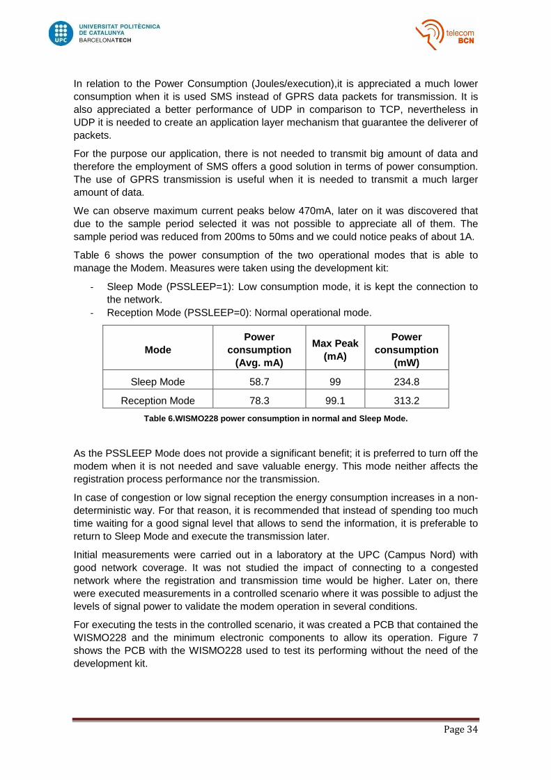
Table 6 shows the power consumption of the two operational modes that is able to
manage the Modem. Measures were taken using the development kit:
- Sleep Mode (PSSLEEP=1): Low consumption mode, it is kept the connection to
the network.
- Reception Mode (PSSLEEP=0): Normal operational mode.
Mode
Power
consumption
(Avg. mA)
Max Peak
(mA)
Power
consumption
(mW)
Sleep Mode 58.7 99 234.8
Reception Mode 78.3 99.1 313.2
Table 6.WISMO228 power consumption in normal and Sleep Mode.
As the PSSLEEP Mode does not provide a significant benefit; it is preferred to turn off the
modem when it is not needed and save valuable energy. This mode neither affects the
registration process performance nor the transmission.
In case of congestion or low signal reception the energy consumption increases in a non-
deterministic way. For that reason, it is recommended that instead of spending too much
time waiting for a good signal level that allows to send the information, it is preferable to
return to Sleep Mode and execute the transmission later.
Initial measurements were carried out in a laboratory at the UPC (Campus Nord) with
good network coverage. It was not studied the impact of connecting to a congested
network where the registration and transmission time would be higher. Later on, there
were executed measurements in a controlled scenario where it was possible to adjust the
levels of signal power to validate the modem operation in several conditions.
For executing the tests in the controlled scenario, it was created a PCB that contained the
WISMO228 and the minimum electronic components to allow its operation. Figure 7
shows the PCB with the WISMO228 used to test its performing without the need of the
development kit.

Page 35
Figure 7. PCB for WISMO228 Evaluation
Table 7 presents a new collection of measures obtained in a controlled scenario using a
power supply of 4.2V and limiting the current to 1A. In previous tests it was used a power
supply of 4V and a current limitation of 500mA, however, during these test it was
appreciated that the Modem was unable to register to low power signal with this
limitations. It was increased the current limitation to 1A and the Power to Supply to 4.2V
and the Modem was able to register. The sample period also changed to 0.02ms instead
of 50ms which allowed us to identify peaks that were not appreciated in previous
measures.
There were executed the same tasks of the previous test but changing the signal level
and band frequency. For these tests it was used the PCB showed instead of the
development kit with a WISMO228, therefore the results presented show the real power
consumption of the Modem.
During the execution of the tests we realized that the WISMO228 module turns off when
the power supply does not satisfy certain current requirements. This phenomenon was
not appreciated in previous tests because the signal level was good enough to let the
device operate with a power supply lower than 500mA at 4V.
In the approaches presented in Table 7, step one consists in turning on the device and
the final step in turning it off. Tests were executed under the following scenarios:
- Two bands: 1800MHz and 900MHz
- Three Signal Levels: good (-46dbm), medium (-80dbm), bad (-93dbm)
- SIM Card Z.

Page 36
Approach Band
Rx Power (dbm)
Execution Time (sec)
Power consumption
(Avg. mA) Max Peak (mA)
Power consumption
(Joules/execution)
SMS Transmission 900 -46 16.6, 16.4 45.2, 45.2 1201, 1180 3.15, 3.11
SMS Transmission 900 -80 17.7, 18.3 47.1, 43.9 1193, 1200 3.5, 3.37
SMS Transmission 900 -93 18.5, 18.6 43.6, 43.6 1189, 1194 3.39, 3.41
SMS Transmission 1800 -46 17.3, 17.1 43.3, 43.4 1004, 1007 3.15, 3.12
SMS Transmission 1800 -80 16.5, 19.5 44.2, 41 1009, 1009 3.06, 3.36
SMS Transmission 1800 -93 16.3, 18.6 43.5, 42.8 1004, 1007 2.98, 3.34
TCP_small 900 -46 54.7, 23.2 50.8, 76 1184, 1183 11.67, 7.41
TCP_small 900 -80 22.8, 20.4 145.1, 151 1248, 1242 13.89, 12.94
TCP_small 900 -93 50.4, 25.2 88.4, 129.4 1223, 1234 18.71, 13.7
TCP_small 1800 -46 24.02, 21.77 61.1, 64.9 1006, 1100 6.16, 5.93
TCP_small 1800 -80 52.5, 22.8, 53.1 57.6, 100.9, 56.8 1006, 1008, 1007 12.7, 9.66, 12.67
TCP_small 1800 -93 20.4, 20.7, 22.4 122.7, 135.2, 115.6 1028, 1029, 1024 10.51, 11.75, 10.88
TCP_big 900 -46 28.53, 27.3 84, 84.3 1194, 1200 10.07, 9.67
TCP_big 900 -80 27.5, 37.2 174.4, 144.9 1222, 1250 20.14, 22.64
TCP_big 900 -93 28.5, 35.4 166.8, 148.5 1239, 1213 19.97, 22.08
TCP_big 1800 -46 27.2, 26.3 72.2, 72.8 1009, 1006 8.25, 8.04
TCP_big 1800 -80 26.8, 25, 26.4, 60
111, 114.4, 117.1, 69 1006,1006,1007,1015
12.49,12.01,12.98, 17.39
TCP_big 1800 -93 26.7, 26.6, 28.5 144.4, 142.6, 137.4 1027, 1025, 1026 16.19, 15.93, 16.45
UDP_small 900 -46 27.3, 25.8 69.4, 80.6 1197, 1209 7.96, 8.73
UDP_small 900 -80 28.6, 25.8 117.8, 127.4 1247, 1250 14.15, 13.81
UDP_small 900 -93 27.8, 28.2 120.5, 117.3 1236, 1211 14.07, 13.89
UDP_small 1800 -46 27.5, 28.2 58.4, 58.8 1006, 1006 6.75, 6.96
UDP_small 1800 -80 57.6, 26.8 58.1, 82 1018, 1008 14.06, 9.23
UDP_small 1800 -93 27.2, 25.7 96.7, 101.3 1021, 1026 11.05, 10.93
UDP_Big 900 -46 30.9, 32.7 74.6, 74.5 1196, 1200 9.68, 10.23
UDP_Big 900 -80 30.9, 65 128.5, 88.1 1233, 1239 16.68, 24.05
UDP_Big 900 -93 30, 30.3 131.5, 138.9 1223, 1223 16.57, 17.68
UDP_Big 1800 -46 31.5, 30.9 60, 64.8 1004, 1008 7.94, 8.41
UDP_Big 1800 -80 64, 64 60.6, 64.1 1004, 1001 16.29, 17.23
UDP_Big 1800 -93 30.9, 64 110.2, 73.2 1025, 1024 14.3, 19.68
Table 7. Power consumption of WISMO228 in a controlled environment adjusting Bands and Signal Levels

Page 37
It is observed that the transmission of SMSs is lightly affected when the signal level
decreases or it is used a different frequency band. On the other hand TCP and UDP
transmissions are more sensitive to variations of the signal level. It is also appreciated
that the power consumption of transmitting big packets is quite similar to the power
consumption of transmitting small packets.
UDP has lower power consumption than TCP; nevertheless it is not a significant
difference. As in UDP there are risk of failed transmissions, sometimes it will be needed
to retransmit packets wasting more energy. Therefore, it is decided to use TCP instead of
UDP as transport mechanism over GPRS.
In order to reduce the power consumption the Modem was configured to manage
predefined Power Classes (CPWC) and Slots Classes. Depending on the Frequency
Band used it was only possible to choose some Power Classes:
- For DCS 1800 Band: CPWC=1->28dbm and CPWC=2->26dbm
- For EGSM 900 Band: CPWC=4->35dbm and CPWC=5->33dbm
- Slots Classes: Class 2->(2Rx,1Tx) Class 10->(4Rx,2Tx)
After several tests it was not appreciated any advantage of changing the Power Class or
Class Slots (see Table 15 in the Annex Section). A possible reason is that this value is
set by the cell and cannot be modified by the Modem.
Using the 900 MHz Band there is bigger power consumption than using the 1800 MHz;
the reason is the larger delay of the registration time for EGSM900 in comparison to
DCS1800, the transmission time is the same for both. In order to spend the lower amount
of energy possible it could be configured the default band to be used by the modem. As
GPRS Class2 or Class10 selection does not affect the power consumption, it will be used
Class10 that provides a better transmission rate (Table 15 in the Annex Section).
This test also allowed us to detect that the antenna connection hardware used in the
embedded board had a worst performance to the used in the devolvement kit; there were
a difference of about 10dbm in the level of signal reception.
The execution of TCP/UDP transmissions have a big delay associated to the activation of
the PDP Context through the command (AT+ACTGT=1,1). It was not possible to reduce
this time and the power consumption.

Page 38
5.3. SARAG350 Analysis
To determine the behavior and current consumption of the modem SARAG350, there
were repeated the same tests prepared for the WISMO228. The SARAG350 could be
removed from the development kit and it was not necessary to consider the current
consumption of the electronic components added in the development kit.
The SARAG350 development kit integrates several modules as GPS module, USB
Module, UART Module, and Power Regulators. In our application none of them is
needed.
Using a Java Program it is automatically send a sequence of AT commands trough the
Serial Port RS232. This program reads the response of the Modem after processing each
AT command, in this way it is assured that the process is executed as fast as it is
possible. Serial Port Communication was kept in the maximum speed; 115200bps and
Minimum Delay of Writing on buffer in 0ms.
Some AT commands can be used in the same way for the WISMO228 and SARAG350,
for example the one related to network registration or SMS transmission. There are other
proprietary AT commands useful for just one modem, for example the related to packet
data transmission. In that way, some of the Java program used for the WISMO228 was
the base for creating the Java program for the SARAG350.
For testing, the power supply was set at 4.5V without setting any current limitation and
the sample period was set to 0.02ms in order to identify current peaks.
Tests were executed under the following scenario:
- LAC: 0852,Cell ID: 1F4E
- Signal Level: 13/99-87dbm
- SIM Card Operator Z.
The SARAG350 module validation procedure consists in obtaining measures of the
energy in Joules consumed by the device when it executes different tasks. Due to the
requirements of the application it was neither tested the Call execution nor the SMS
reception:
- SMS Transmission: Consisting in Registration, SMS transmission and Power Off.
- GPRS Data Transmission using a TCP Socket. Consisting in Registration,
transmission of several TCP Packets containing in total a Payload of 1200 Bytes,
and Power Off.
- GPRS Data Transmission using a UDP Socket. Consisting in Registration,
transmission of several UDP Packets containing in total a Payload of 1200 Bytes,
and Power Off.
To determine the best approach in terms of power consumption it is compared the
amount of Joules needed in each task. It is used the higher execution time and higher
power consumption value to obtain the worst case using Equation 1. Results can be
appreciated in Table 8 and more detailed values are added in the Section Annex Table
16.

Page 39
It is not presented the UDP case because the power consumption is similar that using
TCP. As TCP guarantee transmission in the transport layer is a preferable choice.
SMS SARAG350
TCP SARAG350
Avg. Execution Time (sec)
21,22 Avg. Execution Time
(sec) 31,40
Avg. Consumption (mA) 43,85 Avg. Consumption (mA) 58,21
Avg. Joules/execution (Joules)
3,72 Avg. Joules/execution
(Joules) 7,19
Table 8. SARAG350 power consumption in SMS and TCP_Small transmissions
Table 8 shows that a SMS transmission offers lower power consumption than a TCP one
(More Details in Table 16, Annex Section). The application required in the project does
not need to send big payloads and the transmission of SMSs is the best approach.
Applications with higher data transmission requirements could get benefit of using
TCP/UDP transmissions in comparison to the transmission of several SMSs.
It was also tested the operational range of modem in terms of input voltage from the
power supply. According to the datasheet, the operational range of the SARAG350 was
supposed to be between 3V-4.5V; nevertheless the device did not work properly when
the power supply was lower than 3.2V. A smaller operational range limits the amount of
energy that can be drained from the supercapacitor.
The modem must be configured the first time it is used executing the following sequence
of AT commands:
1) AT+CMEE=2 Enable notifications of errors 2) AT+CPIN? If READY continue, if not Disable PIN 3) AT+CREG=2 Enable notifications of registration to networks 4) AT+CMGF=1 Set SMS format to text mode 5) AT&W0 Save into memory 6) AT+CGDCONT=1,”IP”,”APN” Define PDP Context #1 7) AT+CGACT=1,1 Activate PDP Context #1 8) AT+UPSD=0,1,"APN_name" Set APN name 9) AT+UPSD=0,2,"APN_User" Set User 10) AT+UPSD=0,3,"APN_Password" Set Password 11) AT+UPSDA=0,1 Store Configuration 12) AT+UPSDA=0,3 Activate PSD Profile #0 13) AT+USOCR=6,0 or AT+USOCR=17,0 Create TCP or UDP Socket 14) AT+USOCO=0,"IP_Server ",port Link Socket to remote server 15) USODL=0 Enables end to end transparent com. in socket 0 16) AT&YO Set boot profile 0 17) ATE0 Deactivate Echo 18) AT+CFUN=15 Reboot and saves parameters

Page 40
The AT sequence programmed for transmitting a SMS is started when the “+CREG:1”
sequence announcing the registration to the network is received:
- AT+CREG=2 Enable notifications of errors
- Wait(+CREG:1) Wait registration to network
- AT+CMGS=cellphone_number Set destination number to send SMS
- Wait (“>”) Wait “>” to write the message.
- WRITE 140 characters finishing with ASCII character (\032)
- Wait(+CMGS) Wait receipt of message sent
- AT+CPWROFF Turn off the Modem
The AT sequence used for transmitting TCP or UDP data packets is presented below,
after each received command an OK response has to be waited:
- AT+CREG=2 Enable notifications of errors
- Wait(+CREG:1) Wait registration to network
- AT+CGDCONT=1,"IP","APN_Name" Define PDP Context #1
- AT+CGACT=1,1 Activate PDP Context #1
- AT+UPSD=0,1,"APN_Name" Set APN name
- AT+UPSDA=0,3 Activate PSD Profile #0
o TCP case:
AT+USOCR=6 Create TCP Socket
o UDP case:
AT+USOCR=17,0 Create UDP Socket
- AT+USOCO=0,”IP_Server” Connect to Server
- AT+USODL=0 Link Serial Port buffer to the Socket
established
- Wait(“CONNECT”) Wait connection to the Server
- Send DATA
- Wait (“done”) Wait “done” response from the Server
(Only for the server used)
- +++ Escape sequence
- AT+USOCL=0 Close Socket
- AT+CPWROFF Turn off the Modem

Page 41
5.4. Modem Choice
Modems WISMO228 and SARAG350 performs very similar in terms of energy
consumption, WISMO228 execute a faster registrations but consumes a little more
current and SARAG350 execute a slower registration but consumes lesser; in conclusion
both spend similar amount of energy.
Table 9 shows a comparison table indicating the power consumption of SMS and TCP
transmissions related to both modems. The execution time is higher in the SARAG350
module due to a longer registration time and longer waiting time of acknowledges
responses from the network, for example the acknowledge of SMS received (+CMGS:
ID).
SMS WISMO228 TCP WISMO228
Avg. Execution Time (sec) 19,40 Avg. Execution Time (sec) 24,55
Avg. Consumption (mA) 48,71 Avg. Consumption (mA) 75,62
Avg. Joules/execution (Joules) 3,77 Avg. Joules/execution
(Joules) 7,37
SMS SARAG350 TCP SARAG350
Avg. Execution Time (sec) 21,22 Avg. Execution Time (sec) 31,40
Avg. Consumption (mA) 43,85 Avg. Consumption (mA) 58,21
Avg. Joules/execution (Joules) 3,72 Avg. Joules/execution
(Joules) 7,19
Table 9. WISMO228 and SARAG350 power consumption comparison for SMS and TCP_Small transmission
SARAG350 offers a slightly better performance in terms of energy consumption than
WISMO228, about a 2%; therefore it is needed to study other features of the Modems to
conclude which is the most suitable and beneficial for the application.
Figure 8 shows a comparison of the current consumption of a SMS transmission in both
modems using the power analyzer. The power supply was set to 4V for the WISMO228
and 4,5V for the SARAG350.
Figure 8. Current consumption during a SMS transmission in WISMO228(left) and SARAG350(right)

Page 42
In both cases it is appreciated a first phase with low current consumption associated to
the registration process, during this period the Modem is on and searching available
networks. The second phase starts when the modem registers to the network and tries to
transmit a SMS immediately. The total time spent in all the process depends mostly on
the registration time, once registered the transmission of the SMS and reception of the
receipt usually takes the same amount of time.
As both Modems have a similar performance in terms of energy consumption, Table10
shows a comparison of other features that could help to take the decision of what Modem
to use in the project. The first feature compared is the price, where the SARAG350 is
preferable.
Feature WISMO228 SARAG350
Price (€) 54.75 25
Consumption in SMS
transmissions (J) 3.77 3.72
Consumption in TCP transmission
(J) 7.37 7.19
GPS connectivity None Easy
Adding Modem to prototype Board Easy Hard
AT commands Capabilities Medium Good
Table10. WISMO228 and SARAG350 Comparison (Quantity: 1 Unit)4
In case it is needed a GPS systems, U-blox has designed special GPSs that can be
easily integrated to the Modem SARAG350, however these GPSs are expensive than
others. The integration of a GPS unit to the Modem WISMO228 is not as simple as it is
for the SARAG350 but neither is difficult.
The attachment of the Modem SARAG350 on a PCB is quite hard due to its chip package
with bottom pins and also the number of electronic components needed for its integration.
On the other hand, a WISMO228 is easier to solder because it has a pad layout with
lateral pins only.
Related to AT commands, SARAG350 provides a larger set of AT commands that allow a
better management of data connections and SMTP capabilities. Depending on the
application desired, these capabilities could be useful or not.
After comparing the benefits and drawbacks of each modem, it was decided to implement
the SARAG350 in the final design. The decision was taken in agreement with the client.
4Prices references, (December 2013):
http://es.rs-online.com, http://www.u-blox.com, http://www.aliexpress.com, http://es.farnell.com/, http://www.telit.com/, http://www.tme.eu/.

Page 43
6. Micro Controller Programming
6.1. MC13224V Functionality
The microcontroller is the core unit of the prototype; it will be in charge of managing the
logic, collecting data from external transducers and transmitting information through a
communication interface. The microcontroller must fit several aspects according to the
project requirements:
- Support of Contiki OS.
- Enough processing capacity
- Enough RAM
- Low power consumption
- Communication interfaces: UART, I2C, and SPI.
- ADC and digital inputs and outputs.
- Low cost
- Small size
The MC13224V from Freescale, showed in Figure 9 accomplishes all the features and
also contains a 2.4 GHz wireless communication interface IEEE 802.15.4 which will
allows the connection with WSN devices. As a future improvement, it would be possible
to create an 802.15.4 network between several nodes in order to collect data from
different sensors; the node having the GSM-GPRS can work as a gateway collecting all
data and sending it to external servers.
Moreover, this microcontroller has been tested and used several time by the telematics
group in the UPC for the developing of multiple projects; in all cases there have been
obtained good results.
The size specifications of this microcontroller are:
- LGA145 Package (Land Grid Array)
- 16 pads per size, 9x9 grid of underpaid.
- 9.5mm X 9.5mm
Figure 9.MC13224V Chip Pad Layout.

Page 44
The details of the micro controller functionality are detailed below:
- 32bits ARM7TDMI-S processor that operates up to 26MHz. The simplicity of ARM
processors makes them energy efficient and quite useful in this kind of
applications.
- 128kB Flash memory.
- Operational range of temperature: -40C to 105C.
- Three RAM pages configurable to reach a total of 96kB. In Sleep Mode the
number of active RAM pages can be adjusted to save energy.
- Sleep Mode: The microcontroller has two programmable low consumption modes,
doze mode and hibernate mode, the first one consumes more energy but allows a
quick wake up, the second is defined for long periods of inactivity. Table 11 shows
the different current consumptions according to the capabilities defined.
- 8 ADC channels with a 12 bits resolution and minimum sample time of 20µs.
- 8 KBI control purposes (4 inputs and 4 outputs by default, it can be changed).
- Communication interfaces: 2 configurable UART ports with a maximum speed rate
of 115200bps, one I2C, and two SPI buses.
- It can be connected to a typical oscillator of 24 MHz and an optional one of 32
kHz useful for saving power in case of low demanding applications.
- The microcontroller has a cost of 1.96€.
Table 11.MC1322x Power consumption characteristics
Characteristics Min Typ. Max Unit
Power Supply Operating Voltage 2.0 - 3.6 Vdc
Hibernate current
8 Kbyte RAM retention
32 Kbyte RAM retention
64 Kbyte RAM retention
96 Kbyte RAM retention
0.9
2.3
3.7
5.1
2.2
4.9
-
-
µA
µA
µA
µA
Run current 3.3 7.3 mA
Receiver ON current 22 25 mA
Transmit ON current 29 31 mA
Over the Air Data Rate 250 kbps
Nominal Impedance RF_RX_TX 50

Page 45
Figure 10, shows the pins of the microcontroller. There will be used 3 KBI for controlling
the Scap switch, the Voltage regulator mode, and the Modem switch. It will also be used
a UART interface (UART2) to connect with the Modem, and the UART1 will be left for
programming purposes.
ADCs will be used for sensors and connected to external transducers, some other KBIs
can be connected to switches that disconnect sensors from power supply and avoid extra
current leakages.
Figure 10. MC13224V Pins

Page 46
6.2. Microcontroller Programming
The microcontroller MC13224V was initially tested and programmed in an embedded
platform called Econotag, shown in Figure 11. Most of the libraries used were
programmed by Mariano Alvira and other programmers dedicated to the development of
MC1322x applications, these libraries can be found in https://github.com/contiki-
os/contikias Open Source.
Figure 11.Econotag (MC13224V development Platform)
For programming and flashing the chip it is recommended to use a Linux platform. Even
when it can be used a Virtual Machine to develop projects, sometimes it can cause timing
and flashing problems. Also it is slower than working directly with a native Linux operating
system. Contiki can be programmed directly using any C editor program as Eclipse. In
case of using Eclipse, it has to be configured adding several libraries and a cross
compiler.
Both, Contiki and the MC1322x, have their own library set. As the code will be compiled
and flashed into the MC13224V using a Contiki Operative System both libraries
(MC1322x and Contiki) have to be used. It will be described above the set of steps
needed to configure the working environment in order to program and flash the
microcontroller:
1. Working in a Linux native machine preferable, (also possible using a Virtual
Machine).
2. Download from https://github.com/contiki-os/contiki the official Contiki repository
updated to the last version.
3. Get a tool chain from Sourcery executing the following command lines, this
procedure is explained in details in https://github.com/malvira/libmc1322x/wiki a. Wget http://www.codesourcery.com/sgpp/lite/arm/portal/package3688/public/arm-none-
eabi/arm-2008q3-66-arm-none-eabi.bin
b. /bin/sh arm-2008q3-66-arm-none-eabi.bin
c. PATH=$PATH:$HOME/CodeSourcery/Sourcery_G++_Lite/bin
d. git clone git://git.devl.org/git/malvira/libmc1322x.git
e. cd libmc1322x/tests
f. make BOARD=redbee-dev
g. sudo apt-get install aptitude
h. sudo aptitude install -y libdevice-serialport-perllibterm-readkey-perl
i. $ PATH=$PATH:$HOME/contiki-mc1322x/cpu/mc1322x/tools
j. sudo apt-get install libftdi-dev
k. ~/libmc1322x/tools/ftditools$ make
l. PATH=$PATH:$HOME/libmc1322x/tools
m. ~/libmc1322x/tools$ gcc -c mc1322x-load.c -o mc1322x-load
n. ~/libmc1322x/tools$ chmod 755 mc1322x-load
o. ~/libmc1322x/tools/ftditools$ make

Page 47
p. user@ubuntu:~/libmc1322x/tools$ gccmc1322x-load.c -o mc1322x-load
4. Write the desired code to compile in afilename with *.c extension. E.gtest1.c
5. Create a folder with the same name of the file and put that file and the makefile
there.
6. In order to delete previous data stored in the flash memory of the Econotag it must
be plugged into the USB port and write the command: a. sudo /home/user/libmc1322x/tools/ftditools/bbmc -l redbee-econotag erase
7. Compile the code a. MakeTARGET=redbee-econotag
8. Flash the program in ROM:
a. sudo /home/user/libmc1322x/tools/mc1322x-load -f
/home/user/libmc1322x/tests/flasher_redbee-econotag.bin -s Modem_econotag.bin -t
/dev/ttyUSB1 -c '/home/user/libmc1322x/tools/ftditools/bbmc -l redbee-econotag
reset'
9. Flash the program in RAM:
a. sudo /home/user/libmc1322x/tools/mc1322x-load -f WISMO_econotag.bin -t
/dev/ttyUSB1 -c '/home/user/libmc1322x/tools/ftditools/bbmc -l redbee-econotag
reset'
The microcontroller MC13224V has to be programmed using another platform different to
Econotag (Figure 12.Testing Platform); this platform allows connecting and disconnecting
the microcontroller. The programming steps and libraries are the same used for the
Econotag. This platform does not have external pins to test the functionality. Also the
oscillator is different and the adjustment of the clock must be configured depending on
the platform used.
Figure 12.Testing Platform
Due to the absence of external pins to test the functionality in the Testing Platform, it is
preferable to program and make tests using the Econotag. Once it is tested and
programmed the final code, it can be used the Testing Platform to flash the
microcontroller that will be integrated in the prototype.

Page 48
6.3. Algorithm Design
As the main goal is to save energy, the algorithm was designed to execute a quick
transmission and return to a low power consumption mode for a determined period of
time. The microcontroller is intended to be most of the time in this low power consumption
mode called Sleep Mode. It wakes up periodically to check the battery level and only if
there is enough energy to perform a transmission it enters into Transmission Mode.
The code is planned to be the simpler and lighter possible. It is composed by 4 different
processes:
- Main_process: Main controller of other processes, it is the only process started
when the mode is booted.
- WISMO_process or SARA_process: It is in charge of managing the transmission
of SMS or packet data, it establishes the communication with the modem through
the UART port.
- SerialPort_process: Independent process in charge of managing the UART buffer
for the communication Micro-Modem.
- ADC_process: Collect sensor data and measured the battery level.
Figure 13 shows the flow chart of the global algorithm programmed, there are two
processes always running when the node is not in Sleep Mode, the Main_process which
is the core of the application and the ADC_process which is in charge of sensing the
battery level and other variables.
The ADC_process is periodically sampling the voltage of the supercapacitor and saving
its value in a global variable called Vcap. The Main_process checks this variable Vcap in
order to decide if it returns to Sleep Mode or start the Transmission Mode
(WISMO_process or SARA_Process).
Figure 13. Global Algorithm

Page 49
In case the transmission of data is taking more time than expected the energy
consumption will be higher and it is preferable to put the node in Sleep Mode and execute
the transmission in other time. Therefore it is used a timeout for stopping the
Transmission Mode and returning to Sleep Mode.
As the application does not have any requirements for transmitting information at specific
time, the Transmission Mode is activated just depending on the energy available. If
scheduled times of transmission were needed, there would have to be modified the
algorithm in a way of adjusting fixed periods of Sleep Mode.
6.3.1. Main Program
The Main program is designed as a controller for the rest of the processes; it will be
checking the battery level and the timeout for executing processes. If a process is taking
more time than the expected it will be stopped and the system returned to Sleep Mode
during a determined period of time.
In Figure 14, it can be appreciated that the Main_process consists in an infinite loop
which alternates between two modes, Transmission Mode and Sleep Mode. The amount
of time the process spends in each Mode can be adjusted and will depend on the
application and the energy availability.
WISMO_Process or SARA_Process are constantly sending or receiving AT commands
and data, for the communication with the Modem it is used the SerialPort_process which
is in charge of managing the UART buffer. The sequence of characters received by the
buffer are stored in a Global Variable, in this way the WISMO_Process or SARA_Process
can evaluate this Global Variable and decide which action to take.
Figure 14.Main_process Flow Chart

Page 50
The timeout presented in the flow chart is a general timeout used to stop the
Transmission Mode if it is taking more time than it should (Main Timeout). There is
another timeout inside the WISMO_Process or SARA_Process related to the registration
time (Registration Timeout), this timeout is useful in case there is not network coverage
and the modem cannot register to the network. Therefore it is defined Main Timeout with
a superior value than the Registration Timeout.
Vcap is a global variable obtained directly from the output voltage of the supercapacitor
using an ADC interface. According to its value the Main_process determines if there is
enough energy to start the Transmission Mode or return to Sleep Mode. The Vmin value
will depend on the application, the supercapacitor and the amount of data needed to
transmit.

Page 51
6.3.2. Transmission Mode
This mode is essentially a process oriented to data transmissions. The microcontroller
establishes a Serial Port connection with the Modem through the UART port in order to
send AT commands. It sends AT commands and waits the answer to decide further
actions and continue with the process.
Once connected to the Modem there are several ways of transmitting information, SMS,
E-Mail or to a Server directly using a TCP socket. The data to be send is collected from
different variables, for example ADC inputs or execution times.
This mode presents an internal timeout that aborts the process in case the registration is
taking too much time (Registration Timeout). WISMO228 and SARAG350 require a
similar sequence of AT command for executing the transmission in case of SMS
transmission, nevertheless for TCP/UDP transmission each modem has its own set of
proprietary commands and it was not possible to create a unique code for both modems.
There were created two different codes for each Transmission Mode, SMS transmission
and TCP transmission; both modes consist in sending a set of AT commands (including
the data) through the UART and wait responses to continue the execution. Figure 15
shows the interconnection between Serial Port and WISMO/SARA processes in the
Transmission Mode.
Figure 15. Flow Chart of Transmission Mode

Page 52
Serial Port and WISMO/SARA processes are running as threads in a kind of parallelism.
SerialPort_process store the incoming answer from the buffer in the global variable and
WISMO_Process or SARA_Process read that value in order to determine what action to
take. This parallelism of execution is possible thanks to the use of interruptions in the
Contiki OS.
The interruption of a process is performed using the Contiki function
PROCESS_PAUSE().The function gives time to the CPU to execute other tasks and
processes, also thanks to the use of internal pointers it is possible to return to the same
point before using the PROCESS_PAUSE() function. This function is used in
WISMO/SARA processes after sending any AT command and in the SerialPort_process
after reading the buffer.
The data transmitted to the server is collected from the ADC, KBI inputs and an internal
timer for measuring the Registration Time. It is implemented another process called
ADC_process which periodically sample the ADC and the KBI inputs. These values are
stored in global variables that can be used by the WISMO_Process or SARA_Process for
their transmission. At the end of the ADC_process there is also another
PROCESS_PAUSE() that let other process to run.

Page 53
6.3.3. Sleep Mode
This mode is oriented to save the highest amount of energy possible. Before entering to
this mode all processes except the Main_process are stopped, the modem is turned off
and the TPS62081regulator is put in doze mode. The microcontroller then enters into
hibernate mode, where it waits a timeout for waking up.
The hibernate mode is configurable and adaptable according to the application
requirements, the RAM pages can be adjusted to reduce the current consumption, in this
application only two RAM pages were configured to be retained. It was not possible to
stop completely the MCU and all RAM pages because this leaded to further problems
with the microcontroller in the startup when global pointers to the process got lost.
Also all the KBI must be kept in the last state. In order to guarantee this, the default
values of the KBI were changed to the required state before entering into the Sleep
Mode, in this way they will keep the state desired all the time. In Transmission Mode the
KBIs outputs states can be modified without problem.
The Sleep Mode has to be programmed in a different way using the Econotag and the
Testing Platform, the reason is that both have different oscillators and the clock reference
needs to be adjusted with different values.

Page 54
7. Prototype
7.1. Prototype Tests
Once decided the final design, all tests for programming the micro controller MC13224V
were done in the prototype shown in Figure 16. The final design will embed all this
components in one single PCB. As it can be appreciated there is a battery of 3.7V and
6000mAh, it was used for powering the device and execute multiple tests because the
supercapacitor was only able to send up to 3SMSs with one complete charge to 4.5V. It
was surprising that the battery was capable of supplying the current peaks of almost 3A
without the need of any extra capacitor.
In Figure 16 are presented the main blocks part of the design, the SARAG350 embedded
board connected to a SIM Card interface, the 1.8V Regulator of the microcontroller, the
Switch for controlling the Modem, the microcontroller in its embedded board and the
power Supply (Battery or supercapacitor).
In this prototype there were adjusted the timeouts for registering and transmission. It was
also tested its performance under different environments to certify its operation. The code
algorithm was presented in Section 6.2 and it is based in the periodical transmission of a
single SMS when the energy level was enough to perform this operation. It was also
tested the sending of E-mails through the use of AT proprietary commands.
Figure 16. First Prototype for testing

Page 55
Using a supercapacitor of 3F and 5V, (Charged at 4.5V) the prototype design is able to
send up to 3 SMSs continuously in case of a good signal level. The Sleep Mode
consumes in Average 20uA.
Figure 17 shows the performance of the prototype when it is connected to the power
analyzer, there are observed 4 cycles complete cycles (Transmission and Sleep Modes),
in the third cycle it is simulated a no coverage case removing the antenna (see graph
between the marks m1 and m2). As it can be appreciated, the modem keeps waiting until
the Registration Timeout expires. The avg. current consumption in this cycle is 30mA and
its duration 43.5secs. approx., this represents 4.57Joules with a power supply of 3.5V.
Figure 17. Prototype consumption using SARAG350 (3.5V power supply, unlimited current)
Figure 18 shows the consumption during a typical SMS sending, where the registration
and transmission processes were completed in 20secs. In neither of the cases was
measured nor considered the impact of the network congestion or the moving of the
modem from one location to another at different speeds (Handover).
Figure 18. SMS sending consumption in Prototype using SARAG350 (3.5V power supply, unlimited current)
SleepMode
Without Antenna

Page 56
In order to compute the registration timeout it was measured the registration time
obtaining values in a fixed location. The histogram presented in Figure 19, shows the
results obtained after executing the test 20 times. In 85% of the cases the registration
time is lower than 20secs, so this would be a good value to set. If we take into account
only those values lowers than 20secs the average registration time would be 14.875secs.
Figure 19. Registration Time of Prototype
Figure 20 shows the current consumption of a SMS transmission process using the
prototype test platform. In this case, the transmission process takes 11.4 sec, but in
average the transmission time is 7secs and in 90% of the cases is lower than 15secs.
From these values it is possible to deduce a good value to set for the Main Timeout
(15secs. more than the registration timeout). In conclusion, good values to set for
timeouts would be:
- Registration Timeout: 20 sec.
- Main Timeout: 35 sec.
Figure 20. SMS transmission cost in mA
0
2
4
6
8
10
13 14 15 16 17 18 19 20 21 22 23 24 25 26 27 28 29 30 31 32
Fre
cue
ncy
Registration Time (secs)
Histogram

Page 57
The energy consumed by the prototype depends on the time the device is on and the
time the device is off (Duty Cycle).The transmission process is not initiated when there is
not enough energy to successfully complete a transmission, therefore there will not be
wasted unnecessary energy. Assuming a power supply of 4.5V, the energy consumed in
Joules during a complete cycle (Transmission Time and Sleeping Time) is presented in
Equation 2.
𝐸 = 4.5𝑉 ∗ [[(𝑅𝑒𝑠𝑔𝑖𝑡𝑟𝑎𝑡𝑖𝑜𝑛𝑇𝑖𝑚𝑒)(𝐶𝑢𝑟𝑟𝑒𝑛𝑡𝐶𝑜𝑛𝑠𝑢𝑚𝑝_𝑅𝑒𝑠𝑔𝑖𝑡𝑟𝑎𝑡𝑖𝑜𝑛𝑇𝑖𝑚𝑒) ]
+ ⌈(𝑇𝑟𝑎𝑛𝑠𝑚𝑖𝑠𝑠𝑖𝑜𝑛𝑇𝑖𝑚𝑒)(𝐶𝑢𝑟𝑟𝑒𝑛𝑡𝐶𝑜𝑛𝑠𝑢𝑚𝑝_𝑇𝑟𝑎𝑛𝑠𝑚𝑖𝑠𝑠𝑖𝑜𝑛𝑇𝑖𝑚𝑒) ⌉
+ [(𝑆𝑙𝑒𝑒𝑝𝑖𝑛𝑔𝑇𝑖𝑚𝑒)(𝐶𝑢𝑟𝑟𝑒𝑛𝑡𝐶𝑜𝑛𝑠𝑢𝑚𝑝_𝑆𝑙𝑒𝑒𝑝𝑖𝑛𝑔𝑇𝑖𝑚𝑒) ]]
Equation 2. Power consumption of Prototype test
Based in collected data, the consumption of Transmission Mode in average would be:
𝐸 = 4.5𝑉 ∗ [(15𝑠𝑒𝑐𝑠)(30𝑚𝐴) ] + ⌈(7𝑠𝑒𝑐𝑠)(50𝑚𝐴) ⌉= 3.6 Joules
Equation 3. Power consumption of Prototype test in Transmission Mode (Avg. case)
In the worst case, assuming the modem registers to the network and transmits data just
before the timeouts suspend the process, the energy consumed during Transmission
Mode would be:
𝐸 = 4.5𝑉 ∗ [(20𝑠𝑒𝑐𝑠)(30𝑚𝐴) ] + ⌈(15𝑠𝑒𝑐𝑠)(50𝑚𝐴) ⌉]= 6.075 Joules
Equation 4. Power consumption of Prototype test in Transmission Mode (Worst Case)
Sleeping mode only consumes 0.3 Joules/hour which represents 7.2 Joules per day. With
a complete charge of the supercapacitor (15.02Joules of useful energy) there would
remain 7.2 Joules for executing transmissions which allows sending 2 SMS in average. In
the worst case, assuming 8 hours of artificial light, it would still be possible to send 2 SMS
per day (If there is enough signal for registering and transmitting).

Page 58
7.2. Prototype costs
The final cost of the prototype depends on the modem used and the amount of devices,
Table 12 shows the cost associated to the two possible final PCB that incorporates all the
electronic components (WISMO228 Model or SARAG350 model) which differs only in the
modem used and in certain electronic components for the integration. The prototype
includes the microcontroller, the modem, the supercapacitor and other electronic
components needed in the hardware. The prototype does not include any sensor, just the
capability to connect to them.
Prototype Model Amount (Units) Cost (€)
WISMO228 Model 1 54,75
WISMO228 Model >5 30
SARAG350/QuadBand
Model 1 25
SARAG350/QuadBand
Model >5 19,86
Table 12. Costs of Prototypes depending on the ammount ordered5
In relation to the components prices of each final device, mostly of the cost (almost 70%
of the device) is due to the modem price in the case of using the WISMO228, on the
other hand if it is used a SARAG350 the percentage of the device due to the modem is
less than 60%.
5Prices references, (December 2013):
http://es.rs-online.com, http://www.u-blox.com, http://www.aliexpress.com, http://es.farnell.com/, http://www.telit.com/.

Page 59
8. Conclusions
More often, people are interested in having a complete knowledge of their surrounding
environment, as available services, transport systems and environmental forecast. All
these new requirements can be provided thanks to the rapid growth of ubiquitous
computing and M2M services. These technologies are used by different sectors in order
to provide an extended quality of service and increase the quality of experience of their
clients. The final outcome is the reduction of implementation costs and the formation of a
competitive market.
The use of Mobile Networks to provide M2M services has become one the most accepted
approaches since they provide scalability, easy deployment and already have a
completely deployed infrastructure. Initially, Mobile Networks did not differentiate M2M
services from their other services; therefore it was difficult and costly to use the Mobile
Network for integrating M2M solutions. Nowadays, with the expansion of M2M
applications, Mobile Companies started to create and integrate new ways of providing
cheaper services to allow these installations.
One of the main limitations of WSNs is related to its self-sustainability. Commonly, WSNs
nodes are deployed in vast areas with no power grid connections, using just harvesting
energy source. In order to deal with this limitation of energy, it is proposed and fabricated
a low cost and high energy efficient M2M device capable of monitoring and controlling
external variables. The device uses a harvesting source of energy consisting in a solar
panel capable of working with low luminosity levels (Indoor Environment).
The device is oriented to guarantee low maintenance requirements and capability of
supporting a large number of charging and discharging energy cycles. In order to assure
that, all components were selected taking into account its energy consumption, cost and
performance.
The communication technology to be used is a GSM/GPRS network. This technology
provides enough bandwidth for the amount of data required to transfer in this application
and consumes less energy than a 3G or 4G network could. The data transmission
method depends on the payload size, for big payloads it is used GPRS (data packet
transmission through TCP) and for small payloads SMSs.
It is decided to use the SARAG350 Modem instead of the WISMO228 modem, mostly
due to its cost, better performance and client support. In general, both modems present
similar features in relation to the energy consumption and performance.
It is used the microcontroller MC13224V with Contiki as operative system. This operative
system was proved to be efficient dealing with low memory devices and easy to program
due to several libraries that help to the programming. The algorithm designed is very
simple and block oriented which simplifies the update and adding of new functionalities.
Depending on the application, the microcontroller can be easily reprogrammed to
manage new variables or to update execution timeouts.
Page 60
9. Future Improvements
It was designed a first prototype that could be tested and improved according to the
results and requirements. There are presented above some of these improvements that
could be configured and tested in order to create a more complete solution.
In Sleep Mode, the device consumes about 20 µA which represents 7.2 Joules/day. In
order to reduce this consumption, the microcontroller could be programmed to enter in an
extreme low consumption mode where just one RAM page is available. As there are
problems in the wake up phase when the RAM is not retained, the approach would be to
save the RAM information into the Flash memory before entering to Sleep Mode and
recover it in the wake up.
The device was not tested in roaming and this issue is important in case of mobile nodes
that cross countries. Also, it was only used a solar panel (suitable for indoors) as power
supply, it would be a valuable to try others harvesting sources of energy that could be
adapted to the device.
As GPS units increase the final cost considerably, an alternative proposal could be to use
the Cell-ID value to determine an approximated location. Cell-ID value is obtained in the
registration process and it is not needed extra computing time. This approach was tested
and provides an accuracy of a few hundred of meters depending on the location.
The algorithm can also be improved depending on the application. For example, in case
of failed transmissions a good approach could be to save the data pending to transmit
and send it later as a collection of information. Depending on the amount of information
that is required to transmit there will be needed several SMS or the establishment of a
TCP connection through GPRS.

Page 61
10. Programming Code
10.1. Modem.c
/*
PATH=$PATH:$HOME/CodeSourcery/Sourcery_G++_Lite/bin
sudo /home/user/libmc1322x/tools/ftditools/bbmc -l redbee-econotag erase
sudo /home/user/libmc1322x/tools/mc1322x-load -f WISMO_econotag.bin -t /dev/ttyUSB1 -c
'/home/user/libmc1322x/tools/ftditools/bbmc -l redbee-econotag reset'
sudo /home/user/libmc1322x/tools/mc1322x-load -f
/home/user/libmc1322x/tests/flasher_redbee-econotag.bin -s Modem_econotag.bin -t
/dev/ttyUSB1 -c '/home/user/libmc1322x/tools/ftditools/bbmc -l redbee-econotag reset'
env GIT_SSL_NO_VERIFY=true git clone
https://mgalarza:[email protected]:44356/git/dists/contiki.git
*/
/*Timeouts Management:
-abort: Maximum time it will spend trying to complete complete process (Turn on, Register
and Transmit).(1min)
-Regist_timeout: Maximum time it will spend trying to register after modem is on.(30secs)
Led: It turns on when modem registers and turns off when micro go to sleep.
*/
/*-----------------------LIBRARIES---------------------------*/
#include "contiki.h"
#include <stdio.h> /* For printf() */
#include "dev/leds.h"
#include <string.h>
#include <mc1322x.h>
#include <board.h>
#include "config.h"
#include "tests/tests.h"
#include "Modem.h"
#include "dev/button-sensor.h"
#include <stdlib.h>
/*-----------------------PROCCESS---------------------------*/
PROCESS(Main_process, "Main process"); //Main controller of processes
PROCESS(WISMO_process, "WISMO process");
PROCESS(SARA_process, "SARA process");
PROCESS(SerialPort_process, "Serial Port process");
PROCESS(ADC_process, "ADC Manager");
PROCESS(Events_process, "Events process");
AUTOSTART_PROCESSES(&Main_process);
/*-----------------------THREADS----------------------------*/
PROCESS_THREAD(Main_process, ev, data)
{
PROCESS_BEGIN();
Set_LowConsumption();
Regulator_awake();
leds_init();
Modem_off();
static struct etimer abort, delay;
process_start(&ADC_process, NULL);
etimer_set(&delay, CLOCK_SECOND*3);
PROCESS_WAIT_EVENT_UNTIL(etimer_expired(&delay));
//Waiting for UART starting...
/*For Econotag:*/
disable_irq(UART2);
uart_flowctl(UART2, 1);
uart_init(UART2, 115200);
/*For Testing Platform:*/
/*disable_irq(UART1);
uart_flowctl(UART1, 1);
uart_init(UART1, 115200);*/
//goto_sleep_chip(1);
goto_sleep_econotag(1);

Page 62
while(1){
PROCESS_PAUSE();
Registered=0;
if(Vcapacitor>1000){//3.8V approx...
printf("\n\rStarting SerialPort and Modem Transmission\n\r");
attempts++;
process_start(&SerialPort_process, NULL);
process_start(&SARA_process, NULL);
Modem_on(); //Scap_on();
current_time=clock_seconds();
etimer_set(&abort, CLOCK_SECOND*90); //70 for sms, 90 for email
while(process_is_running(&SARA_process) && ! etimer_expired(&abort)){
//Keep running until process ends or timeout occurs (60secs). && !etimer_expired(&abort)
PROCESS_PAUSE();
}
process_exit(&SARA_process);
process_exit(&SerialPort_process);
Modem_off(); //Scap_off();
}
leds_off(1);
Registered=0;
//goto_sleep_chip(60); //go to sleep for 60secs...
printf("sleep");
goto_sleep_econotag(10); //go to sleep for 15secs...
}
PROCESS_END();
}
PROCESS_THREAD(SARA_process, ev, data)
{
PROCESS_BEGIN();
static struct etimer Regist_timeout,data_timer, delay;
char LAC[4], CID[4];
etimer_set(&data_timer, CLOCK_SECOND*3); //Adjust this value depending data size.
/*---------------------REGISTRATION----------------------------*/
etimer_set(&Regist_timeout, CLOCK_SECOND*40); //Adjust this value depending
Registration timeout.
while(wait_response("INFO:")){
if (etimer_expired(&Regist_timeout)){PROCESS_EXIT();}
PROCESS_PAUSE();
}
send_UART("AT+CREG=2;+CMEE=2\r");
while(wait_response("OK")){PROCESS_PAUSE();}
while(wait_response("+CREG: 1,")){
if (etimer_expired(&Regist_timeout)){PROCESS_EXIT();}
PROCESS_PAUSE();
}
Registered=1;
current_time=clock_seconds()-current_time;
leds_on(1);
char buffer0[8],buffer1[8],buffer2[8],buffer3[8];
/*---------------------------SMS SENDING--------------------*/
/* send_UART("AT+CMGD=4\r");
while(wait_response("OK")){PROCESS_PAUSE();}
send_UART("at+cmgw=\"664877095\"\r");
while(wait_response(">")){PROCESS_PAUSE();}
sprintf(buffer0,"%d",adc_vbatt);
send_UART("SARAG350 msg:\nMicro_Vbat:");
send_UART(buffer0);
send_UART("mV\n");
sprintf(buffer1,"%d",Vcapacitor);
send_UART("Vcap:");
send_UART(buffer1);
send_UART("mV\n");
sprintf(buffer2,"%d",attempts);
send_UART("Attempts:");
send_UART(buffer2);
send_UART("\n");
sprintf(buffer3,"%d",current_time);
send_UART("Registration time:");
send_UART(buffer3);
send_UART("sec\n;)");
send_UART("\x1A");
while(wait_response("OK")){PROCESS_PAUSE();}
send_UART("AT+CMSS=4\r");

Page 63
while(wait_response("OK")){
if(Error==1){
send_UART("AT+CMSS=4\r");
etimer_set(&delay, CLOCK_SECOND*3);
PROCESS_WAIT_EVENT_UNTIL(etimer_expired(&delay)); //Trying
again...
}
PROCESS_PAUSE();
}
*/
/*------------------TCP TRANSMISSION--------------------*/
/*send_UART("at+cgdcont=1,\"IP\",\"internet\"\r");
while(wait_response("OK")){PROCESS_PAUSE();}
send_UART("at+cgact=1,1\r");
while(wait_response("OK")){PROCESS_PAUSE();}
send_UART("at+upsd=0,1,\"internet\"\r");
while(wait_response("OK")){PROCESS_PAUSE();}
send_UART("at+upsda=0,3\r");
while(wait_response("OK")){PROCESS_PAUSE();}
send_UART("at+usocr=6\r");
while(wait_response("OK")){PROCESS_PAUSE();}
send_UART("at+usoco=0,\"147.83.39.81\",50005\r");
while(wait_response("OK")){PROCESS_PAUSE();}
send_UART("at+usodl=0\r");
while(wait_response("CONNECT")){PROCESS_PAUSE();}
send_UART("Se envian caracteres ASCII -+*++*+\n");
while(wait_response("done")){PROCESS_PAUSE();}
etimer_set(&delay, CLOCK_SECOND*1);
PROCESS_WAIT_EVENT_UNTIL(etimer_expired(&delay));
send_UART("+++");
while(wait_response("OK")){PROCESS_PAUSE();}
send_UART("at+usocl=0\r");
while(wait_response("OK")){PROCESS_PAUSE();}
*/
/*------------------EMAIL TRANSMISSION--------------------*/
/*
send_UART("at+cgdcont=1,\"IP\",\"internet\";+cgact=1,1;+upsd=0,1,\"internet\";+upsda=0,3\r
");
while (wait_response("OK")){PROCESS_PAUSE();}
send_UART("AT+USMTP=1,\"smtp.mail.yahoo.com\";+USMTP=2,\"[email protected]\";+USMTP=3,\"MC
1322X_UPC\"\r"); //MC1322X_UPC, [email protected]
while (wait_response("OK")){PROCESS_PAUSE();}
send_UART("AT+USMTP=4,1;+USMTP=5,3600\r"); //MC1322X_UPC, [email protected]
while (wait_response("OK")){PROCESS_PAUSE();}
send_UART("AT+UDNSRN=0,\"smtp.mail.yahoo.com\"\r");
while (wait_response("OK")){PROCESS_PAUSE();}
send_UART("AT+USMTPM=0,\"[email protected]\";+USMTPM=1,\"[email protected]\"\r");
while (wait_response("OK")){PROCESS_PAUSE();}
send_UART("AT+USMTPM=2,\"[email protected]\"\r");
while (wait_response("OK")){PROCESS_PAUSE();}
send_UART("AT+USMTPM=3,\"SARAG350\"\r");
while (wait_response("OK")){PROCESS_PAUSE();}
send_UART("AT+USMTPM=4,\"Values:\n");
sprintf(buffer0,"%d",adc_vbatt);
send_UART("Mic_Vbat:");
send_UART(buffer0);
send_UART("mV\n");
sprintf(buffer1,"%d",Vcapacitor);
send_UART("Vcap:");
send_UART(buffer1);
send_UART("mV\n");
sprintf(buffer2,"%d",attempts);
send_UART("Attempts:");
send_UART(buffer2);
send_UART("\n");
sprintf(buffer3,"%d",current_time);
send_UART("Regist.time:");
send_UART(buffer3);
send_UART("sec\n;)\"\r");
while (wait_response("OK")){PROCESS_PAUSE();}
send_UART("at+USMTPC=1\r");
while (wait_response("+UUSM")){PROCESS_PAUSE();}
send_UART("at+USMTPC=2\r");
while (wait_response("+UUSM")){PROCESS_PAUSE();}

Page 64
*/
/*-----------------OFF & END PROCESS--------------------------*/
send_UART("AT+CPWROFF\r");
while(wait_response("OK")){PROCESS_PAUSE();}
PROCESS_END();
}
PROCESS_THREAD(WISMO_process, ev, data)
{
PROCESS_BEGIN();
static struct etimer Regist_timeout,data_timer;
char LAC[4], CID[4];
etimer_set(&Regist_timeout, CLOCK_SECOND*30); //Adjust this value depending
Registration timeout.
etimer_set(&data_timer, CLOCK_SECOND*2); //Adjust this value depending data size.
/*---------------------REGISTRATION----------------------------*/
while(wait_response("+CREG: 1,")){
if (etimer_expired(&Regist_timeout)){PROCESS_EXIT();}
PROCESS_PAUSE();
}
Registered=1;
//leds_on(1);
/*---------------------------SMS SENDING--------------------*/
/* printf("\r\n Sending SMS: \r\n");
send_UART("at+cmgs=\"664877095\"\r");
while(wait_response(">")){PROCESS_PAUSE();}
send_UART("Hola, es WISMO228 \x1A");
while(wait_response("+CMGS")){PROCESS_PAUSE();}
*/
/*------------------TCP TRANSMISSION--------------------*/
/* printf("\r\nTCP TRANSMISSION: \r\n");
send_UART("at+wipcfg=1\r");
while(wait_response("OK")){PROCESS_PAUSE();}
send_UART("at+cgact=1,1\r");
while(wait_response("OK")){PROCESS_PAUSE();}
send_UART("at+wipbr=1,6\r");
while(wait_response("OK")){PROCESS_PAUSE();}
send_UART("at+wipbr=4,6,0\r");
while(wait_response("OK")){PROCESS_PAUSE();}
send_UART("at+wipcreate=2,1,\"147.83.39.81\",50005\r");
while(wait_response("+WIPREADY:")){PROCESS_PAUSE();}
send_UART("at+wipdata=2,1,2\r");
while(wait_response("CONNECT")){PROCESS_PAUSE();}
send_UART("Se envian caracteres ASCII -+*++*+\n");
etimer_restart(&data_timer); PROCESS_WAIT_EVENT_UNTIL(etimer_expired(&data_timer));
//Sending DATA...
while(wait_response("done")){PROCESS_PAUSE();}
send_UART("+++");
while(wait_response("OK")){PROCESS_PAUSE();}
send_UART("at+wipclose=2,1\r");
while(wait_response("OK")){PROCESS_PAUSE();}
/*-----------------OFF & END PROCESS--------------------------*/
send_UART("at+cpof\r");
while(wait_response("OK")){PROCESS_PAUSE();}
PROCESS_END();
}

Page 65
PROCESS_THREAD(SerialPort_process, ev, data)
{
PROCESS_BEGIN();
char data[]=" ";
while(1) {
PROCESS_PAUSE();
/*if(uart1_can_get()) { //Something in buffer UART1?
uart2_putc(uart1_getc());
}*/
if(uart2_can_get()) { //Something in buffer UART?
data[0]=uart2_getc();
strcat(text,data);
if (data[0]=='>'||data[0]=='\r'||data[0]=='\x1A') { //Update
Response when '>' '\r' 'CTRL-Z' is received.
//If(strstr(Response,"ERROR")!=NULL &&
Registered==1){process_exit(&SARA_process);process_start(&SARA_process, NULL);} //SEND /A
//If(strstr(Response,"ERROR")) {continue;/*Manage ERRORS:*/}
//SEND /A
strcpy(Response,text);
printf("%s",Response);
memset(text,0,30); //Clear Text
}
}
}
PROCESS_END();
}
PROCESS_THREAD(ADC_process, ev, data)
{
PROCESS_BEGIN();
static struct etimer ADC;
adc_init();
adc_setup_chan(2); //(ADC2 GPIO_32)
adc_setup_chan(3); //(ADC3)
while(1){
adc_service();
//printf("%u %04u %04u mV\r\n", 2, adc_reading[2], adc_voltage(2));
//printf("Vbatt mc1322x: %d mV\n\r", adc_vbatt);
Vcapacitor=adc_reading[2];
Sensor1=adc_reading[3];
PROCESS_PAUSE();
}
PROCESS_END();
}

Page 66
PROCESS_THREAD(Events_process, ev, data)
{
PROCESS_BEGIN();
leds_init();
//Set_LowConsumption();
static struct etimer events;
#define WRITE_NBYTES 8
#define WRITE_ADDR 0x1e000
#define WRITEVAL0 0xdeadbeef
#define WRITEVAL1 0xdeadbeef
//nvmType_t type=0;
nvmErr_t err;
//uint32_t buf[WRITE_NBYTES/4];
uint32_t buf[WRITE_NBYTES];
uint32_t send[WRITE_NBYTES];
uint32_t i;
while(1){
//PROCESS_PAUSE();
Modem_on();leds_on(1);
//vreg_init();
err = nvm_read(gNvmInternalInterface_c, 0, (uint8_t *)buf,WRITE_ADDR,WRITE_NBYTES);
printf("nvm_read returned: 0x%02x\r\n", err);
printf("reading\r\n");
/*
for(i=0; i<WRITE_NBYTES; i++) {
printf("0x%08x\r\n", (unsigned int)buf);
}
err = nvm_erase(gNvmInternalInterface_c, 0, 1 << WRITE_ADDR/4096);
printf("nvm_erase returned: 0x%02x\r\n", err);
err = nvm_read(gNvmInternalInterface_c,0,(uint8_t *)buf,WRITE_ADDR,WRITE_NBYTES);
printf("nvm_read returned: 0x%02x\r\n", err);
printf("reading\r\n");
for(i=0; i<WRITE_NBYTES/4; i++) {
printf("0x%08x\r\n", (unsigned int)buf[i]);
}
buf[0] = 0xdeadbeef;
buf[1] = 0xdeadbeef;
*/
send[1] = 0xdeadbeef;
err = nvm_write(gNvmInternalInterface_c,0,(uint8_t *)send,WRITE_ADDR,WRITE_NBYTES);
printf("nvm_write returned: 0x%02x\r\n", err);
//printf("writing\n\r");
//for(i=0; i<WRITE_NBYTES; i++) {
// printf("0x%08x\r\n", (unsigned int)buf[i]);
// buf[i] = 0x00000000; /* clear buf for the read */
//}
err = nvm_read(gNvmInternalInterface_c, 0, (uint8_t *)buf, WRITE_ADDR,
WRITE_NBYTES);
printf("nvm_read returned: 0x%02x\r\n", err);
printf("reading\r\n");
printf("0x%08x\r\n", (unsigned int)buf);
etimer_set(&events,
CLOCK_SECOND*2);PROCESS_WAIT_EVENT_UNTIL(etimer_expired(&events));
printf("go to sleep");
//etimer_set(&events,
CLOCK_SECOND/2);PROCESS_WAIT_EVENT_UNTIL(etimer_expired(&events));
//goto_sleep_chip(5);//go to sleep for 5secs...
Modem_off(); leds_off(1);
goto_sleep_econotag(10);
//goto_sleep_chip(20);
//PROCESS_WAIT_EVENT_UNTIL(ev == event);
//PROCESS_PAUSE();
//process_post(&Blink_process, blink_event, NULL);//Post async event
}
PROCESS_END();
}

Page 67
10.2. Modem.h
/*Global Varibles*/
char text[160];
char Response[160];
int Vcapacitor;
int Registered;
int current_time;
int attempts=0;
int Sensor1;
int Error=0;
/*Function that sends String through UART (char by char)*/
void send_UART(char text[]){
int i;
for(i=0;i<strlen(text);i++){
uart2_putc(text[i]);
}
}
/*Function that waits a determined string sequence and clear "Response" variable*/
int wait_response(char comparison[]){
if(strstr(Response, comparison)==NULL){ //Waiting response
if(strstr(Response, "ERROR")!=NULL){Error=1;}
return 1;
}
else { //Response received
memset(Response,0,160);
return 0;
Error=0;
}
}
/*Turn On Scap KBI1*/
void Scap_on(void){
GPIO->DATA.GPIO_23 = 1;
}
/*Turn Off Scap KBI1*/
void Scap_off(void){
GPIO->DATA.GPIO_23 = 0;
}
/*Turn On Modem KBI2*/
void Modem_on(void){
//GPIO->PAD_DIR.GPIO_24 = 1; //set as output
GPIO->DATA.GPIO_24 = 1;
}
/*Turn Off Modem KBI2*/
void Modem_off(void){
GPIO->DATA.GPIO_24 = 0;
}
/*Turn On Current Regulator KBI3*/
void Regulator_awake(void){
//GPIO->PAD_DIR.GPIO_25 = 1; //set as output
GPIO->DATA.GPIO_25 = 0;
}
/*Turn Off Current Reglator KBI3*/
void Regulator_asleep(void){
//GPIO->PAD_DIR.GPIO_25 = 1; //set as output
GPIO->DATA.GPIO_25 = 1;
}
/* Function that puts Micro (Econotag) in Sleep Mode. It is based in rtimer_arch_sleep
from rtimer-arch.c */

Page 68
void goto_sleep_econotag(rtimer_clock_t howlong)
{
clock_delay_msec(2000); //Needed in case of unfinihed proccesses.
CRM->WU_CNTLbits.EXT_OUT_POL = 8; //(4bits) [KBI3 KBI2 KBI1 KBI0]-->[1 0 0 0]
CRM->WU_CNTLbits.TIMER_WU_EN = 1;
CRM->WU_CNTLbits.RTC_WU_EN = 0;
CRM->WU_TIMEOUT = howlong*2000; //2000 is 1 secs.
/* the maca must be off before going to sleep *//* otherwise the mcu will reboot on
wakeup */
maca_off();
Regulator_asleep();
CRM->SLEEP_CNTLbits.DOZE = 0;
CRM->SLEEP_CNTLbits.RAM_RET = 2; //(2bits), [0->8kbytes, 1->32kbytes, 2-
>64kbytes, 3->96kbytes]
CRM->SLEEP_CNTLbits.MCU_RET = 1;
CRM->SLEEP_CNTLbits.DIG_PAD_EN = 0;
CRM->SLEEP_CNTLbits.HIB = 1;
/* wait for the sleep cycle to complete */
while((*CRM_STATUS & 0x1) == 0) { continue; }
/* write 1 to sleep_sync --- this clears the bit (it's a r1wc bit) and powers down
*/
*CRM_STATUS = 1;
/* asleep */
/* wait for the awake cycle to complete */
while((*CRM_STATUS & 0x1) == 0) { continue; }
/* write 1 to sleep_sync --- this clears the bit (it's a r1wc bit) and finishes
wakeup */
*CRM_STATUS = 1;
Regulator_awake();
CRM->WU_CNTLbits.TIMER_WU_EN = 0;
CRM->WU_CNTLbits.RTC_WU_EN = 1;
/* reschedule clock ticks */
clock_init();
clock_adjust_ticks((CRM->WU_COUNT*CLOCK_CONF_SECOND)/rtc_freq);
}
void goto_sleep_chip(rtimer_clock_t howlong)
{
clock_delay_msec(2000); //Needed in case of unfinihed proccesses.
//clear_bit(*CRM_RINGOSC_CNTL,0); /* enable the 32kHZ crystal */
set_bit(*CRM_XTAL32_CNTL,0);
/* set the XTAL32_EXISTS bit *//* the datasheet says to do this after you've
check that RTC_COUNT is changing, the datasheet is not correct */
set_bit(*CRM_SYS_CNTL,5);
{
static volatile uint32_t old;
old = *CRM_RTC_COUNT;
while(*CRM_RTC_COUNT == old) {
continue;
}
/* RTC has started up */
set_bit(*CRM_SYS_CNTL,5);
}
CRM->WU_CNTLbits.EXT_OUT_POL = 8; //(4bits) [KBI3 KBI2 KBI1 KBI0]-->[1 0 0 0]
CRM->WU_CNTLbits.TIMER_WU_EN = 1;
CRM->WU_CNTLbits.TIMER_WU_EN = 1;
CRM->WU_CNTLbits.RTC_WU_EN = 0;
CRM->WU_TIMEOUT = 32768*howlong;
/* the maca must be off before going to sleep *//* otherwise the mcu will reboot on
wakeup */
maca_off();

Page 69
Regulator_asleep();
CRM->SLEEP_CNTLbits.DOZE = 0;
CRM->SLEEP_CNTLbits.RAM_RET = 2; //(2bits), [0->8kbytes, 1->32kbytes, 2->64kbytes,
3->96kbytes]
CRM->SLEEP_CNTLbits.MCU_RET = 1;
CRM->SLEEP_CNTLbits.DIG_PAD_EN = 0;
CRM->SLEEP_CNTLbits.HIB = 1;
/* wait for the sleep cycle to complete */
while((*CRM_STATUS & 0x1) == 0) { continue; }
/* write 1 to sleep_sync --- this clears the bit (it's a r1wc bit) and powers down
*/
*CRM_STATUS = 1;
/* asleep */
/* wait for the awake cycle to complete */
while((*CRM_STATUS & 0x1) == 0) { continue; }
/* write 1 to sleep_sync --- this clears the bit (it's a r1wc bit) and finishes
wakeup */
*CRM_STATUS = 1;
Regulator_awake();
CRM->WU_CNTLbits.TIMER_WU_EN = 0;
CRM->WU_CNTLbits.RTC_WU_EN = 1;
/* reschedule clock ticks */
clock_init();
clock_adjust_ticks((CRM->WU_COUNT*CLOCK_CONF_SECOND)/rtc_freq);
}
/* Configure pullups for low power consumption*/
void Set_LowConsumption(){
GPIO->FUNC_SEL.GPIO_63 = 3;
GPIO->PAD_PU_SEL.GPIO_63 = 0;
GPIO->FUNC_SEL.SS = 3;
GPIO->PAD_PU_SEL.SS = 1;
GPIO->FUNC_SEL.VREF2H = 3;
GPIO->PAD_PU_SEL.VREF2H = 1;
GPIO->FUNC_SEL.U1RTS = 3;
GPIO->PAD_PU_SEL.U1RTS = 1;
}

Page 70
11. Bibliography
1. Nuevas tendencias GSM para M2M: SIM Electrónica y UMTS 900MHz. Jesús Santos
2. End-to-End M2M (Sample/Excerpts Copy Only – Not Full Report) Conceived and written by Stephen M. Dye; published by www.MindCommerce.com.
3. M2M Project Management. Stefan GONNET [email protected] Marketing Manager Radio Resource Allocation in LTE-Advanced Cellular Networks with M2M Communications.
4. KanZheng¤, Senior Member, IEEE, Fanglong Hu¤, Wei Xiangy, Senior Member, IEEE, MischaDohler, Senior Member, IEEEz and Wenbo Wang¤, Member, IEEE
5. White Paper: Power Considerations for 2G&3G Modules in MID Designs, Option Wireless Technologies.
Manuals:
6. MC1322x Advanced ZigBee™- Compliant SoC Platform for the 2.4 GHz IEEE®
802.15.4 Standard Reference Manual. Document Number: MC1322xRM Rev. 1.6
01/2012.
7. AT Command Manual for Firmware L23. Air Prime WS Series.
WA_DEV_WISMO_UGD_012, Rev004, November 3, 2011.
8. Product Technical Specification& Customer Design Guidelines. AirPrime WISMO218. WA_DEV_W218_PTS_002, Rev007, September 10, 2010
9. SARA-G350 GSM/GPRS modules Data Sheet. GSM.G2-HW-12001-2. 2012. 10. U-blox Wireless Modules. Data and Voice Modules. AT Commands Manual. WLS-
SW-11000-C. 2012. 11. AT Commands Examples. Examples for U-blox wireless modules. Application
Note. WLS-CS-11003
WEB Links:
12. http://www.contiki-os.org/
13. https://github.com/contiki-os/contiki
14. http://www.giovynet.com/
15. http://www.etsi.org/
16. http://www.3gpp.org
17. http://sourcecodemania.com/sockets-and-network-programming-in-java/
18. http://www.radio-electronics.com/info/cellulartelecomms/gsm_technical/power-
control-classes-amplifier.php
19. http://www.blogelectronica.com/gps/datosGSM.php?mcc=214&mnc=01&lac=0820
&cid=20dc
20. http://www.xatakandroid.com/operadoras/primeros-pasos-con-android-principales-
apn-para-configurar-los-moviles
21. http://m2m.com/servlet/JiveServlet/previewBody/1003-102-2-
1006/Whitepaper_01.pdf
22. http://www.redeweb.com/_txt/641/76.pdf

Page 71
23. http://www.ericsson.com/res/thecompany/docs/publications/ericsson_review/2011/
m2m_remotesubscriptions.pdf
24. http://www.adaptivem2m.com/gprs-modem/modems.htm
25. http://www.machinetomachinemagazine.com/2011/11/14/telefonica-and-giesecke-
devrient-team-up-on-m2m-sims/
26. http://www.aunclicdelastic.com/machine-to-machine/modulos-m2m-3g-mejores-
que-2g-a-largo-plazo/
27. http://machine2twomachine.wordpress.com/2011/08/25/machine-2-machine-
internet-of-things-real-world-internet/
28. http://ipv6day.orangelabs.es/
29. http://wiki.maemo.org/N900_Hardware_Power_Consumption

Page 72
12. Annex
Part Number WISMO 218 SARA-G3 series
LEON-G100 LEON-G200 M55i MC75i 863-GPS 864-GPS GC-864 Quad
Manufacturer Wavecom U-blox U-blox U-blox Cinterion Cinterion Telit Telit Telit Input Voltage 3.2V - 4.8V 3V – 4.5V 3V - 4.5V 3V - 4.5V 3.3V - 4.8V
3.2V - 4.5V 3.2V - 4.5V 3.2V - 4.5V 3.2V - 4.5V
Current Off Mode
36 µA 60 µA 90 µA 90 µA 50 µA 50 µA 26 µA 62 µA 26 µA
Current Idle Mode
1.3 mA DRX9 1 mA 1 mA DRX9 1 mA
DRX9
2.5 mA
DRX9
3.7 mA
DRX9
2.6 mA GPS off
1.5 mA
DRX9
GPS off
2.6 mA
Current GPRS (transmission) Mode
369 mA class10 240 mA class10
410 mA class10
410 mA class10
450 mA class10
475mAclass10 370 mA class10 420 mA class10 370 mA class10
GPIO 11 4 4 4 N. A. N. A. 18 10 4 A/D, D/A converter interface
2 N.A. 1 N. A. N. A. N. A. 3 3 22
USSD Yes N. A. Yes Yes Yes Yes Yes Yes Yes Protocols TCP, UDP,
SMTP, FTP TCP, UDP, HTTP, FTP
TCP, UDP, HTTP, FTP
TCP, UDP, HTTP, FTP
TCP, UDP, HTTP, FTP
TCP, UDP, HTTP, FTP
TCP, UDP, SMTP, FTP
TCP, UDP, SMTP, FTP
TCP, UDP, SMTP, FTP
Network Access
GSM, GPRS, SMS
GSM, GPRS, SMS
GSM, GPRS, SMS
GSM, GPRS, SMS
GSM, GPRS, SMS
GSM, GPRS, SMS, EDGE
GSM, GPRS, SMS
GSM, GPRS, SMS
GSM, GPRS, SMS
Bands Dual Band Quad Band Quad Band Quad Band Quad Band Quad Band Quad Band Quad Band Quad Band Temperature -30Cto+75C -40Cto +85C -40Cto +85C -40Cto
+85C
-40Cto
+70C
-40Cto +75C -40Cto+85C -40Cto+85C -40Cto+85C
Size 25x25x2.8 mm 16x26x3 mm 19X30X3 mm 19X30X3 mm 35x33x3 mm 34x35x3.5 mm 41X31X3.6 mm 30X30X2.8 mm 30X37X3 mm Integrated GPS No No No No No No Yes Yes No Price 49.9€ 25€ 85€ 95€ 65€ 85€ 100€ 56€ 105€
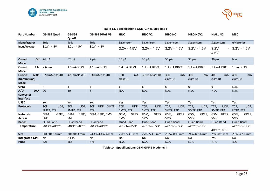
Page 73
Table 13. Specifications GSM-GPRS Modems I
Part Number GE-864 Quad GE-864 Quad2
GE-865 DUAL V3 HILO HILO V2 HILO NC HILO NCV2 HIALL NC M80
Manufacturer Telit Telit Telit Sagemcom Sagemcom Sagemcom Sagemcom Sagemcom uMicronics Input Voltage 3.2V - 4.5V 3.2V - 4.5V 3.2V - 4.5V
3.2V - 4.5V 3.2V - 4.5V 3.2V - 4.5V 3.2V - 4.5V 3.2V -
4.6V
3.3V - 4.6V
Current Off Mode
26 µA 62 µA 2 µA 35 µA 35 µA 56 µA 35 µA 36 µA N.A.
Current Idle Mode
2.6 mA 1.5 mADRX9 1.1 mA DRX9 1.4 mA DRX9 1.1 mA DRX9 1.4 mA DRX9 1.1 mA DRX9 1.4 mA DRX9 1 mA DRX9
Current GPRS (transmission) Mode
370 mA class10 420mAclass10 330 mA class10 360 mA class10
361mAclass10 360 mA class10
360 mA class10
400 mA class10
450 mA class10
GPIO 4 3 3 6 6 6 6 6 N.A. A/D, D/A converter interface
20 10 8 N.A. N.A. N.A. N.A. N.A. N.A.
USSD Yes Yes Yes Yes Yes Yes Yes Yes Yes Protocols TCP, UDP,
SMTP, FTP TCP, UDP, SMTP, FTP
TCP, UDP, SMTP, FTP
TCP, UDP, SMTP, FTP
TCP, UDP, SMTP, FTP
TCP, UDP, SMTP, FTP
TCP, UDP, SMTP, FTP
TCP, UDP, SMTP, FTP
TCP, UDP, HTTP, FTP
Network Access
GSM, GPRS, SMS
GSM, GPRS, SMS
GSM, GPRS, SMS GSM, GPRS, SMS
GSM, GPRS, SMS
GSM, GPRS, SMS
GSM, GPRS, SMS
GSM, GPRS, SMS
GSM, GPRS, SMS
Bands Quad Band Quad Band Dual Band Quad Band Quad Band Quad Band Quad Band Quad Band Quad Band Temperature -40Cto+85C -40Cto+85C -40Cto+85C -40Cto+85C -40Cto+85C -40Cto+85C -40Cto+85C -
40Cto+85C -45Cto+85C
Size 30X30X2.8 mm 30X30X3 mm 24.4x24.4x2.6mm 27x27x3.6 mm 27x27x3.6 mm 28.5x34x3 mm 24x24x2.6 mm 29x34x3 mm 23x25x2.6 mm Integrated GPS No A-GPS No No No No No Yes No Price 52€ 46€ 47€ N. A. N. A. N. A. N. A. N. A. 49€
Table 14. Specifications GSM-GPRS Modems II

Page 74
Figure 21. Network Registration of WISMO228 using the development kit
Figure 22.Sleep and Normal Mode Change in WISMO228 using the development kit

Page 75
Figure 23.SMS Transmission in WISMO228 using the development kit
Figure 24.GPRS Transmission TCP in WISMO228 using the development kit

Page 76
Figure 25.GPRS Transmission UDP in WISMO228 using the development kit
Figure 26.Reception Mode in WISMO228 using the development kit

Page 77
Figure 27 WISMO228 Development Kit
Figure 28 SARA G350 Development Kit

Page 78
Band PWC Class Slots
Current Avg (mA)
Current Peak (mA) Time
1800 1 10 83,3 1 27,6
1800 1 10 67,1 1 28,5
1800 1 10 78,4 1 23
1800 1 2 62 1 30,9
1800 1 2 77,4 1 23,1
1800 1 2 72 1 24,3
1800 2 10 79 1 28,2
1800 2 10 73 1 26,7
1800 2 10 74,7 1 26,6
EGSM 4 10 74,6 1,2 42,6
EGSM 4 10 67,5 1,2 41
EGSM 4 10 71 1,23 42,6
EGSM 5 10 70 1,23 41
EGSM 5 10 72,2 1,2 40
EGSM 5 10 71,3 1,3 42
Table 15 Power consumption comparison of WISMO228 related to Bands, PWC and GPRS Mode.

Page 79
Approach MODEM Band Execution Time (sec)
Power current (Avg. mA)
Max Peak (mA)
Power consumption (Joules/execution)
SMS Transmission SARAG350 1800 23,27 40,9 968 3,81
SMS Transmission SARAG350 1800 22,9 42,5 975,9 3,89
SMS Transmission SARAG350 1800 22,22 42,1 973,7 3,74
SMS Transmission SARAG350 1800 20,27 46,4 970 3,76
SMS Transmission SARAG350 1800 20,12 45,1 973,8 3,63
SMS Transmission SARAG350 1800 20,57 45,4 972,3 3,74
SMS Transmission SARAG350 1800 21,92 43,2 970,2 3,79
SMS Transmission SARAG350 1800 20,42 43,7 970,2 3,57
SMS Transmission SARAG350 1800 19,67 44,6 973,4 3,51
SMS Transmission SARAG350 1800 20,86 44,6 972,2 3,72
SMS Transmission WISMO228 1800 18,43 51,6 1004 3,80
SMS Transmission WISMO228 1800 21,17 48,8 929,5 4,13
SMS Transmission WISMO228 1800 18,62 48,5 993,2 3,61
SMS Transmission WISMO228 1800 20,12 47,6 992,4 3,83
SMS Transmission WISMO228 1800 17,72 50 995 3,54
SMS Transmission WISMO228 1800 20,42 48,2 979,5 3,94
SMS Transmission WISMO228 1800 20,57 49 980 4,03
SMS Transmission WISMO228 1800 20,72 45,1 981,8 3,74
SMS Transmission WISMO228 1800 18,47 48,4 979,1 3,58
SMS Transmission WISMO228 1800 17,72 49,9 992,5 3,54
TCP_Small SARAG350 1800 28,83 58,5 983,7 6,75
TCP_Small SARAG350 1800 33,6 46,1 987 6,20
TCP_Small SARAG350 1800 25,33 57,6 984,8 5,84
TCP_Small SARAG350 1800 25 61 988,2 6,10
TCP_Small SARAG350 1800 25,03 53,3 989,3 5,34
TCP_Small SARAG350 1800 27,93 57,2 986,5 6,39
TCP_Small SARAG350 1800 24,29 54,7 988,8 5,31
TCP_Small SARAG350 1800 59,41 43,1 989,1 10,24
TCP_Small SARAG350 1800 35,48 85,9 986,7 12,19
TCP_Small SARAG350 1800 29,13 64,7 984,8 7,54
TCP_Small WISMO228 1800 23,4 71,3 1020 6,67
TCP_Small WISMO228 1800 25,67 78,6 1029 8,07
TCP_Small WISMO228 1800 23,27 78,9 1017 7,34
TCP_Small WISMO228 1800 22,37 74,3 1015 6,65
TCP_Small WISMO228 1800 21,77 77,1 1035 6,71
TCP_Small WISMO228 1800 25,68 73,5 1014 7,55
TCP_Small WISMO228 1800 21,47 83,1 1017 7,14
TCP_Small WISMO228 1800 22,52 80,2 1014 7,22
TCP_Small WISMO228 1800 33,64 63,2 998,9 8,50
TCP_Small WISMO228 1800 25,68 76 1016 7,81
Table 16 SARAG350 and WISMO228 power consumption values collected

Page 80