design and fabrication of multipurpose vehicle
TRANSCRIPT

ISSN (Print) : 2320 – 3765
ISSN (Online): 2278 – 8875
International Journal of Advanced Research in Electrical,
Electronics and Instrumentation Engineering
(An UGC Approved Journal)
Vol. 6, Issue 8, August2017
Copyright to IJAREEIE
Design and Fabrication of Multipurpose
Vehicle
Ali Imran S1*
, Bilal U1, Gohar M
2
1COMSATS University of Science & Technology, Sahiwal, Punjab, Pakistan
2Department of Mathematics, Shanghai University, Shanghai, China
Abstract: In the era of mechanical world you have to deal with new technology and ideas so the first thing is design
which should be stable in surrounding. To get the final product we will use such a frame which can be modified for car,
boat and as well as for helicopter. Frame have to deal with three type of moving objects so it is important to analysis
before it’s fabrication, that it can bear forces. We should have to visualize it’s modification and material.
Keywords: Fabrication; Design analysis; Meshing; Simulation; Shear stress
I. INTRODUCTION
We have to analysis different materials for best result that can help to bear the forces. The software solid works is used
here to check elasticity of different materials. This belongs to static simulation in solid works [1,2]. There are different
types of helicopter and here we are dealing with a flying machine having rotor above and tail rotor. Helicopter is such a
vehicle which don’t need runway and can make stable itself by different mechanisms. But there are complexions for its
flight so we have to deal with different theories to solve complexions like momentum theory of hover, vortex theory,
moment theory of climb, element theory, dynamic theories for blades power losses due to drag and flight for forward,
rear, and right side [3]. In fluid dynamics, the momentum theory or disk actuator theory is a theory describing a
mathematical model of an ideal actuator disk; the rotor is modeled as an infinitely thin disc, inducing a constant
velocity along the axis of rotation. The basic state of a helicopter is hovering. This disc creates a flow around the rotor.
Under certain mathematical premises of the fluid, there can be extracted a mathematical connection between power,
radius of the rotor, torque and induced velocity. The rotor is modeled as an infinitely thin disc, inducing a constant
velocity along the axis of rotation. The basic state of a helicopter is hovering. This disc creates a flow around the rotor.
Under certain mathematical premises of the fluid, there can be extracted a mathematical connection between power,
radius of the rotor, torque and induced velocity [4]. For a helicopter it is important study about the blades and blade
element theory is an important article it is a mathematical process It involves breaking a blade down into several small
parts then determining the forces on each of these small blade elements. These forces are then integrated along the
entire blade and over one rotor revolution in order to obtain the forces and moments produced by the entire propeller or
rotor. One of the key difficulties lies in modeling the induced velocity on the rotor disk. Because of this the blade
element theory is often combined with the momentum theory to provide additional relationships necessary to describe
the induced velocity on the rotor disk [5]. Blades have very importance for the flight of helicopter, blades we are going
to use made of aluminum and have all properties of aerodynamics, symmetrical blade of naca with airfoil database
coordinates(naca 0012) [6]. Data are presented for lift coefficients from near zero through maximum values at Mach
numbers from 0.30 to 0.86 and Reynolds numbers of 3.0 × 10 to the sixth power with transition fixed. A limited
amount of data is presented near zero and maximum lift for a Reynolds number of 6.0 × 10 to the sixth power with
transition fixed. In addition, transition free data is presented through the Mach number range from 0.30 to 0.86 for near
zero lift and a Reynolds number of 3.0 × 10 to the sixth power [7]. The analysis of the two dimensional subsonic flow
over a National Advisory Committee for Aeronautics (NACA) 0012 air foil at various angles of attack and operating at
a Reynolds number of 3 × 10⁶ is presented. The flow was obtained by solving the steady-state governing equations of
continuity and momentum conservation combined with one of three turbulence models [shear stress transport (SST)]
aiming to the validation of these models through the comparison of the predictions and the free field experimental
measurements for the selected air foil. The aim of the work was to show the behaviour of the air foil at these conditions

ISSN (Print) : 2320 – 3765
ISSN (Online): 2278 – 8875
International Journal of Advanced Research in Electrical,
Electronics and Instrumentation Engineering
(An UGC Approved Journal)
Vol. 6, Issue 8, August2017
Copyright to IJAREEIE
and to establish a verified solution method. The computational domain was composed of 80000 cells emerged in a
structured way, taking care of the refinement of the grid near the air foil in order to enclose the boundary layer
approach. Calculations were done for constant air velocity altering only the angle of attack for every turbulence model
tested. This work highlighted two areas in computational fluid dynamics (CFD) that require further investigation:
transition point prediction and turbulence modelling. The laminar to turbulent transition point was modeled in order to
get accurate results for the drag coefficient at various Reynolds numbers. In addition, calculations showed that the
turbulence models used in commercial CFD codes does not give yet accurate results at high angles of attack [8]. A
comprehensive data base is given for the low speed aerodynamic characteristics of the NACA 0012 airfoil section. The
Langley low-turbulence pressure tunnel is the facility used to obtain the data. Included in the report are the effects of
Mach number and Reynolds number and transition fixing on the aerodynamic characteristics. Presented are also
comparisons of some of the results with previously published data and with theoretical estimates The Mach number
varied from 0.05 to 0.36. The Reynolds number, based on model chord, varied from 3 × 10 to the 6th to 12 × 10 to the
6th power [9]. To get actual results of helicopter blades, 8in × 10 feet cord and length of blade respectively simulated
done in software solid works the results were close to actual report the results are for maximum and minimum rpm and
also for maximum angle of attack and for minimum angle of attack [10]. A portable boat for all commercial and
recreational uses, with particular application to shallow water situations. The boat comprises a multi-tube flotation
perimeter hull constructed of connected, epoxy-laminated foam cores and totally encased with a vinyl polyester fabric;
a reinforced floor portion and, a full rear transom means. This water craft is strong, yet flexible, unsinkable and
virtually impervious to punctures and abrasion damage. These positive benefits are accomplished without sacrificing
the advantages of lightweight construction and ease of transportation [11]. Mechanism for transmitting power to two
members from a common power source, one of these members having to be driven continuously and the other having
either to be halted, to be driven by said common power source, or to be used as a motor for driving the rest member
which is then disconnected from the source. Such a power transmitting mechanism can be applied to helicopters with
advantage, the first continuously driven member being the hydraulic, electrical or pneumatic ancillary systems and the
second member the rotor or rotors [12]. A model helicopter rotor pitch control mechanism is provided. The mechanism
comprises a seesaw; a stabilizer bar attached to said seesaw; a mixing lever pivotally supported by said stabilizer bar,
said mixing lever having a first end and a second end; an upper swash lever to which said first end is connected by way
of a rod and a main rotor grip to which said second end is connected by way of said rodn [13]. A stabilizer bar has an
aerodynamically shaped member, such as a winglet, on opposite ends thereof, and the bar is connected to rotate on its
longitudinal axis and is mounted to tilt about a pivot axis at right angles thereto connecting it to a rotor shaft that also
carries a pair of rotor blades the pitch of which can be changed about their longitudinal axis, that is parallel with the
stabilizer bar pivot axis. A pair of oppositely directed mixing levers on opposite sides of the rotor shaft and connected
parallel with the stabilizer bar for tilting movement there with is connected by first control linkages to diametrically
opposite sides of a wobble plate assembly, and by second control linkages to vary the pitch of the pair of rotor blades.
An arm attached to the stabilizer bar in the plane of the aerodynamically shaped members has an end disposed in
alignment with the pivot axis of the stabilizer bar that is connected by a control rod to the wobble plate assembly 90°
from the connections of the first control linkages, for cyclic adjustments of the pitch of the aerodynamically shaped
members [14].
1.1. Objective
• The objective of this project is to design and fabricate such an automative that can fly, run and as well as float
on water.
• purpose to facilitate the users for three different rides in a singleoautomotive vehicle.
• This vehicle wold be very helpfull for military purpose. You can take any ride at any time at any situation,
whether you want to cross a road or water or mountains.
• Here are some steps we are going to take to complete our objectiveOptimization of the controller gains of
2DOF controllers such as 2DOF-PI, 2DOF-PID and 2DOF-IDD controller in a two area wind thermal system using
FPA.
1.2. Aim of Work
• Structural designe in software.
ISSN (Print) : 2320 – 3765
ISSN (Online): 2278 – 8875
International Journal of Advanced Research in Electrical,
Electronics and Instrumentation Engineering
(An UGC Approved Journal)
Vol. 6, Issue 8, August2017
Copyright to IJAREEIE
• Simulation of different structure and blades.
• Fabrication.
• Assembling (that make possible to can Fly, run and float over water).
1.3. Methodology
The methodology is show in Figure 1.
Figure 1: Methodology.
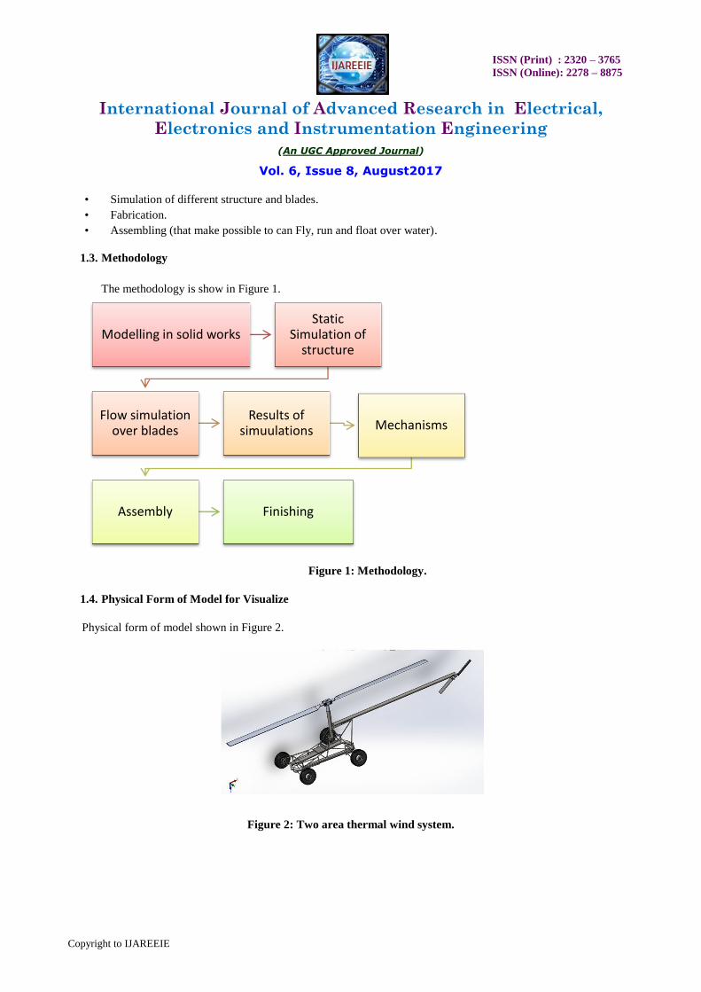
1.4. Physical Form of Model for Visualize
Physical form of model shown in Figure 2.
Figure 2: Two area thermal wind system.
Modelling in solid works Static
Simulation of structure
Flow simulation over blades
Results of simuulations Mechanisms
Assembly Finishing

ISSN (Print) : 2320 – 3765
ISSN (Online): 2278 – 8875
International Journal of Advanced Research in Electrical,
Electronics and Instrumentation Engineering
(An UGC Approved Journal)
Vol. 6, Issue 8, August2017
Copyright to IJAREEIE
II. STRUCTURE SIMULATION
Here the basic structure is simulated for different materials under 4000 N force from the front side which different
nodes which shows that how much force it can bear. First i use Aluminimum (6063-T6) and then steel (ANSI 4130
steel normalized at 870c) and after that i simulate for iron (ductile iron).
Simulation results shows that iron is best to that we can use in our structure and is easily available in Pakistan (Table
1).
Simulation of Chassis
Date: Thursday, July 27, 2017
Designer: Ali imran
Study name: basic frame
Analysis type: Static
Table of Contents
Description 1
Assumptions 2
Model Information 2
Study Properties 7
Units 7
Material Properties 8
Loads and Fixtures 9
Connector Definitions 10
Contact Information 10
Mesh information 11
Sensor Details 11
Resultant Forces 12
Beams 13
Study Results 18
Conclusion 19
Table 1: Simulation of chassis.
2.1. Description
It is about the simulation for the structure of vehicle.
2.2. Assumptions
In this we assume that the base is fixed and 3500 N force is applied normal to the top plane to check the stability of
structure under that force.

ISSN (Print) : 2320 – 3765
ISSN (Online): 2278 – 8875
International Journal of Advanced Research in Electrical,
Electronics and Instrumentation Engineering
(An UGC Approved Journal)
Vol. 6, Issue 8, August2017
Copyright to IJAREEIE
2.3. Model Information
Model information showm in Table 2.
Model name: Chassis 2
Current Configuration: Predeterminado<Como mecanizada>
Beam Bodies:
Document Name and Reference Formulation Properties
Beam-1(Recortar/Extender18)
Beam – Uniform C/S
Section Standard-iso/pipe/14.2 ×
1.65
Section Area: 6.50545e-005m2
Length: 841.994 mm
Volume: 5.47295e-005 m3
Mass Density: 7100 kg/m3
Mass: 0.388579 kg
Weight: 3.80808 N

ISSN (Print) : 2320 – 3765
ISSN (Online): 2278 – 8875
International Journal of Advanced Research in Electrical,
Electronics and Instrumentation Engineering
(An UGC Approved Journal)
Vol. 6, Issue 8, August2017
Copyright to IJAREEIE
Beam-2(Miembro estructural5)
Beam – Uniform C/S
Section Standard-iso/pipe/14.2 ×
1.65
Section Area: 6.50545e-005 m2
Length: 502.075 mm
Volume: 3.26402e-005 m3
Mass Density: 7100 kg/m3
Mass: 0.231745 kg
Weight: 2.2711 N
Beam-3(Recortar/Extender13)
Beam – Uniform C/S
Section Standard-iso/pipe/14.2 ×
1.65
Section Area: 6.50545e-005 m2
Length:884.548 mm
Volume:5.74797e-005 m3
Mass Density:7100 kg/m3
Mass:0.408106 kg
Weight:3.99944 N
Beam-4(Recortar/Extender13)
Beam – Uniform C/S
Section Standard-iso/pipe/22.2 ×
1.65
Section Area: 0.000106524 m2
Length:754.507 mm
Volume:8.04211e-005 m3
Mass Density:7100 kg/m3
Mass:0.57099 kg
Weight:5.5957 N
Beam-5(Recortar/Extender5)
Beam – Uniform C/S
Section Standard-iso/pipe/22.2 ×
1.65
Section Area: 0.000106524 m2
Length:1619.52 mm
Volume:0.000172169 m3
Mass Density:7100 kg/m3
Mass:1.2224 kg
Weight:11.9795 N

ISSN (Print) : 2320 – 3765
ISSN (Online): 2278 – 8875
International Journal of Advanced Research in Electrical,
Electronics and Instrumentation Engineering
(An UGC Approved Journal)
Vol. 6, Issue 8, August2017
Copyright to IJAREEIE
Beam-6(Recortar/Extender2)
Beam – Uniform C/S
Section Standard-iso/pipe/14.2 ×
1.65
Section Area: 6.50545e-005 m2
Length:969.942 mm
Volume:6.31334e-005 m3
Mass Density:7100 kg/m3
Mass:0.448247 kg
Weight:4.39282 N
Beam-7(Recortar/Extender19)
Beam – Uniform C/S
Section Standard-iso/pipe/22.2 ×
1.65
Section Area: 0.000106524 m2
Length:735.41 mm
Volume:7.8341e-005 m3
Mass Density:7100 kg/ m3
Mass:0.556221 kg
Weight:5.45097 N
Beam-8(Miembro estructural5)
Beam – Uniform C/S
Section Standard-iso/pipe/14.2 ×
1.65
Section Area: 6.50545e-005 m2
Length:236.633 mm
Volume:1.53758e-005 m3
Mass Density:7100 kg/ m3
Mass:0.109168 kg
Weight:1.06985 N
Beam-9(Recortar/Extender17)
Beam – Uniform C/S Section Standard-iso/pipe/14.2 ×
1.65
Section Area: 6.50545e-005 m2
Length:859.654 mm
Volume:5.54902e-005 m3
Mass Density:7100 kg/ m3
Mass:0.393981 kg
Weight:3.86101 N

ISSN (Print) : 2320 – 3765
ISSN (Online): 2278 – 8875
International Journal of Advanced Research in Electrical,
Electronics and Instrumentation Engineering
(An UGC Approved Journal)
Vol. 6, Issue 8, August2017
Copyright to IJAREEIE
Beam-10(Recortar/Extender14)
Beam – Uniform C/S
Section Standard-iso/pipe/14.2 ×
1.65
Section Area: 6.50545e-005 m2
Length:884.646 mm
Volume:5.74884e-005 m3
Mass Density:7100 kg/ m3
Mass:0.408168 kg
Weight:4.00004 N
Beam-11(Recortar/Extender4)
Beam – Uniform C/S
Section Standard-iso/pipe/22.2 ×
1.65
Section Area: 0.000106524 m2
Length:583.915 mm
Volume:6.22305e-005 m3
Mass Density:7100 kg/ m3
Mass:0.441836 kg
Weight:4.33 N
Beam-12(Recortar/Extender8)
Beam – Uniform C/S
Section Standard-iso/pipe/14.2 ×
1.65
Section Area: 6.50545e-005 m2
Length:728.445 mm
Volume:4.7377e-005 m3
Mass Density:7100 kg/ m3
Mass:0.336377 kg
Weight:3.29649 N
Beam-13(Miembro estructural7)
Beam – Uniform C/S Section Standard-iso/pipe/14.2 ×
1.65
Section Area: 6.50545e-005 m2
Length:469.584 mm
Volume:3.05191e-005 m3
Mass Density:7100 kg/ m3
Mass:0.216686 kg
Weight:2.12352 N

ISSN (Print) : 2320 – 3765
ISSN (Online): 2278 – 8875
International Journal of Advanced Research in Electrical,
Electronics and Instrumentation Engineering
(An UGC Approved Journal)
Vol. 6, Issue 8, August2017
Copyright to IJAREEIE
Beam-14(Recortar/Extender18)
Beam – Uniform C/S
Section Standard-iso/pipe/22.2 ×
1.65
Section Area: 0.000106524 m2
Length:735.414 mm
Volume:7.8367e-005 m3
Mass Density:7100 kg/ m3
Mass:0.556406 kg
Weight:5.45278 N
Beam-15(Miembro structural5)
Beam – Uniform C/S
Section Standard-iso/pipe/14.2 ×
1.65
Section Area: 6.50545e-005 m2
Length:235.632 mm
Volume:1.53185e-005 m3
Mass Density:7100 kg/ m3
Mass:0.108761 kg
Weight:1.06586 N
Beam-16(Recortar/Extender15)
Beam – Uniform C/S
Section Standard-iso/pipe/14.2 ×
1.65
Section Area: 6.50545e-005 m2
Length:850.724 mm
Volume:5.52962e-005 m3
Mass Density:7100 kg/ m3
Mass:0.392603 kg
Weight:3.84751 N
Beam-17(Recortar/Extender19)
Beam – Uniform C/S
Section Standard-iso/pipe/14.2 ×
1.65
Section Area: 6.50545e-005 m2
Length:861.334 mm
Volume:5.59916e-005 m3
Mass Density:7100 kg/ m3
Mass:0.397541 kg
Weight:3.8959 N

ISSN (Print) : 2320 – 3765
ISSN (Online): 2278 – 8875
International Journal of Advanced Research in Electrical,
Electronics and Instrumentation Engineering
(An UGC Approved Journal)
Vol. 6, Issue 8, August2017
Copyright to IJAREEIE
Beam-18(Recortar/Extender10)
Beam – Uniform C/S
Section Standard-iso/pipe/22.2 ×
1.65
Section Area: 0.000106524 m2
Length:1619.52 mm
Volume:0.000172158 m3
Mass Density:7100 kg/ m3
Mass:1.22232 kg
Weight:11.9788 N
Beam-19(Recortar/Extender4)
Beam – Uniform C/S
Section Standard-iso/pipe/14.2 ×
1.65
Section Area: 6.50545e-005 m2
Length:968.814 mm
Volume:6.3026e-005 m3
Mass Density:7100 kg/ m3
Mass:0.447484 kg
Weight:4.38535 N
.
Beam-20(Miembro estructural8)
Beam – Uniform C/S
Section Standard-iso/pipe/14.2 ×
1.65
Section Area: 6.50545e-005 m2
Length:738.248 mm
Volume:4.80264e-005 m3
Mass Density:7100 kg/ m3
Mass:0.340987 kg
Weight:3.34168 N
Table 2: Model information shown.
2.4. Study Properties
Study properties of modal shown in Table 3.

ISSN (Print) : 2320 – 3765
ISSN (Online): 2278 – 8875
International Journal of Advanced Research in Electrical,
Electronics and Instrumentation Engineering
(An UGC Approved Journal)
Vol. 6, Issue 8, August2017
Copyright to IJAREEIE
Study name Basic frame
Analysis type Static
Mesh type Beam Mesh
Solver type Direct sparse solver
In plane Effect Off
Soft Spring Off
Inertial Relief Off
Incompatible bonding options Automatic
Large displacement Off
Compute free body forces On
Result folder SOLIDWORKS
document
Table 3: Study properties.
2.5. Units
Units for modal shown in Table 4.
Unit system: SI (MKS)
Length/Displacement mm
Temperature Kelvin
Angular velocity Rad/sec
Pressure/Stress N/ m2
Table 4: Units for modal.
2.6. Material Properties
Material Properties for modal shown in Table 5.
Model Reference Properties Components
Name: Ductile Iron SolidBody 1(Recortar/Extender18)(Chassis 2),
Model type: Linear Elastic
Isotropic
SolidBody 2(Miembro estructural5)(Chassis 2),
Default failure
criterion:
Max von Mises
Stress
SolidBody 3(Recortar/Extender16)(Chassis 2),
Yield strength: 5.51485e+008
N/m2
SolidBody 4(Recortar/Extender13[1])(Chassis 2),
Tensile
strength:
8.61695e+008
N/m2
SolidBody 5(Recortar/Extender5)(Chassis 2),

ISSN (Print) : 2320 – 3765
ISSN (Online): 2278 – 8875
International Journal of Advanced Research in Electrical,
Electronics and Instrumentation Engineering
(An UGC Approved Journal)
Vol. 6, Issue 8, August2017
Copyright to IJAREEIE
Elastic
modulus:
1.2e+011 N/m2 SolidBody 6(Recortar/Extender2)(Chassis 2),
Poisson's ratio: 0.31 SolidBody 7(Recortar/Extender19)(Chassis 2),
Mass density: 7100 kg/m3 SolidBody 8(Miembro estructural5)(Chassis 2),
Shear modulus: 7.7e+010 N/m2 SolidBody 9(Recortar/Extender17)(Chassis 2),
Thermal
expansion
coefficient:
1.1e-005 /Kelvin SolidBody 10(Recortar/Extender14)(Chassis 2),
SolidBody 11(Recortar/Extender4)(Chassis 2),
SolidBody 12(Recortar/Extender8)(Chassis 2),
SolidBody 13(Miembro estructural7)(Chassis 2),
SolidBody 14(Recortar/Extender18)(Chassis 2),
SolidBody 15(Miembro estructural5)(Chassis 2),
SolidBody 16(Recortar/Extender15)(Chassis 2),
SolidBody 17(Recortar/Extender19)(Chassis 2),
SolidBody 18(Recortar/Extender10)(Chassis 2),
SolidBody 19(Recortar/Extender4)(Chassis 2),
SolidBody 20(Miembro estructural8)(Chassis 2)
Curve Data: N/A
Table 5: Material Properties for modal.
2.7. Loads and Fixtures
Fixtures and Loads for the modal shown in Tables 6a and 6b.
Fixture name Fixture Image Fixture Details
Fixed-1
Entities: 5 Joint(s)
Type: Fixed
Geometry
5 Joint(s)
Fixed
Geometry
Table 6a: Fixtures for the modal.
Load name Load Image Load Details
Force-1
Entities: 1 plane(s), 2 Joint(s)
Reference: Alzado
Type: Apply force
Values: ---, ---, 4000 N
Moments: ---, ---, --- N.m

ISSN (Print) : 2320 – 3765
ISSN (Online): 2278 – 8875
International Journal of Advanced Research in Electrical,
Electronics and Instrumentation Engineering
(An UGC Approved Journal)
Vol. 6, Issue 8, August2017
Copyright to IJAREEIE
Table 6b: Loads for the modal.
2.8. Connector Definitions
In this type simulation joint connection are used (Table 7).
Mesh type: Beam Mesh.
Total Nodes 654
Total Elements 647
Time to complete mesh(hh;mm;ss): 00:00:05
Computer name:
Sensor Details: No Data
Table 7: Simulation joint connection.
2.9. Resultant Forces
Resultant forces are shown in Tables 8a and 8b.
Reaction forces:
Selection set Units Sum X Sum Y Sum
Z Resultant
Entire Model N 0 4.58E-05 -8000 8000
Table 8a: Reaction forces.
Reaction moments:

ISSN (Print) : 2320 – 3765
ISSN (Online): 2278 – 8875
International Journal of Advanced Research in Electrical,
Electronics and Instrumentation Engineering
(An UGC Approved Journal)
Vol. 6, Issue 8, August2017
Copyright to IJAREEIE
Selection set Units Sum X Sum Y Sum Z Resultant
Entire Model N.m 1.974 -41.8032 25.1283 48.8143
Table 8b: Reaction forces.
Beams:
Table 9 shows the beams for modal.
Beam Name Joints Axial(N) Shear1(N) Shear2(N) Moment1
(N.m)
Moment2
(N.m)
Torque
(N.m)
Beam-1
(Recortar/Extender1
8)
1 0 0 0 0 0 0
2 0 0 0 0 0 0
Beam-2
(Miembro
estructural5)
1 -40.0169 0.537179 -2.66546 -1.39843 1.06968 -0.0528
2 40.0169 -0.53717 2.66549 2.7367 -0.8 0.052801
Beam-3
(Recortar/Extender1
6)
1 83.2541 -2.49757 23.1447 -0.67384 -0.42627 -1.62257
2 1236.2 -12.3295 62.1854 19.5964 4.39345 5.46851
3 -83.2541 2.4977 -23.1447 -6.37262 -0.33417 1.62257
Beam-4
(Recortar/Extender1
3)
1 0 0 0 0 0 0
2 0 0 0 0 0 0
Beam-5
(Recortar/Extender5
)
1 -32.2843 -8.33024 27.224 10.1458 2.58291 1.57174
2 30.3626 13.5015 -21.9962 -9.29866 -5.2024 -1.47819
3 32.2843 8.33023 -27.224 10.7174 3.80096 -1.57175
Beam-6
(Recortar/Extender2
)
1 -3109.61 2.02089 -13.6337 -0.51535 -0.83889 -2.30182
2 3109.61 -2.02093 13.6337 -3.45106 0.250515 2.30182
3 -3097.82 -7.07085 1.98845 0.522619 2.52537 -1.22846
Beam-7
(Recortar/Extender1
9)
1 -1120.78 80.9452 -39.4193 21.5301 42.3837 14.5386
2 1121.6 -80.2633 41.0491 8.19046 15.7565 -14.524
3 1120.78 -80.9452 39.4193 -21.315 -41.942 -14.5386
Beam-8
(Miembro
estructural5)
1 -30.7501 -9.97106 19.7017 -1.25194 -1.54023 0.434858
2 30.8713 9.51257 -19.7388 -3.38194 -0.73978 -0.44265
Beam-9
(Recortar/Extender1
7)
1 -1123.14 2.03797 6.54529 -0.13198 0.035793 2.26522

ISSN (Print) : 2320 – 3765
ISSN (Online): 2278 – 8875
International Journal of Advanced Research in Electrical,
Electronics and Instrumentation Engineering
(An UGC Approved Journal)
Vol. 6, Issue 8, August2017
Copyright to IJAREEIE
2 1123.14 -2.03857 -6.54576 5.84027 -1.81378 -2.26522
Beam-10
(Recortar/Extender1
4)
1 -54.7123 0.596797 -25.3643 6.21567 0.027132 -1.79176
2 -2126.98 13.6375 -56.5479 17.9579 4.51776 5.0185
3 -54.6196 -0.44915 -25.5663 -0.99893 0.083215 -1.88085
Beam-11
(Recortar/Extender4
)
1 0 0 0 0 0 0
2 0 0 0 0 0 0
Beam-12
(Recortar/Extender8
)
1 -5511.2 -9.36763 1.99804 -1.49085 -0.96445 -1.84576
2 5511.21 -4.81002 3.16763 -0.73142 -2.21235 1.84857
Beam-13
(Miembro
estructural7)
1 1732.17 1.53026 -0.48636 0.86666 6.28292 0.010904
2 -1731.84 8.28008 -33.069 0.158441 -4.04222 0.068035
Beam-14
(Recortar/Extender1
8)
1 -1963.06 -76.3519 -37.4036 19.8284 -40.5568 -13.6683
2 1963.06 76.3522 37.413 7.10556 -14.4167 13.6683
Beam-15
(Miembro
estructural5)
1 18.4393 7.80705 -19.0907 -0.74406 -1.10577 0.743421
2 -18.5428 -8.19836 18.8245 -3.71311 -0.81325 -0.74836
Beam-16
(Recortar/Extender1
5)
1 1996.36 -1.3643 5.89712 -5.48878 -1.32482 2.10449
2 -1996.36 1.36325 -5.89627 0.34605 0.134622 -2.10449
Beam-17
(Recortar/Extender1
9)
1 -1.94264 0.097391 0.002419 0.000927 -0.0291 0.086961
2 1.94264 -0.09739 -0.00242 0.001209 -0.05691 -0.08696
Beam-18
(Recortar/Extender1
0)
1 -17.6287 12.5074 -15.3478 6.49639 4.74013 -1.69907
2 -18.7444 6.40297 -19.133 -7.52362 -3.08562 -1.8066
3 17.6287 -12.5074 15.3478 6.41326 5.78034 1.69907
Beam-19
(Recortar/Extender4
)
1 -4575.23 3.63362 9.34393 -0.16405 -1.15494 2.52382
2 4575.22 -12.3043 -5.72179 2.82964 -0.15588 -2.5189
3 -4553.9 -9.65857 -1.05629 -0.17314 3.39869 0.921853
Beam-20
(Miembro
estructural8)
1
4463.51
-2.41114
-3.44493
0.732984
-1.3731
-1.96406
2 -4463.13 55.0289 20.4017 2.2173 -1.83042 1.98254

ISSN (Print) : 2320 – 3765
ISSN (Online): 2278 – 8875
International Journal of Advanced Research in Electrical,
Electronics and Instrumentation Engineering
(An UGC Approved Journal)
Vol. 6, Issue 8, August2017
Copyright to IJAREEIE
Table 9: Beams for modal.
Beam stresses:
Tables 10a- 10c shows the Beam Stresses for modal.
Beam Name
Joints
Axial(N/m2)
Bending Dir1
(N/m2)
Bending
Dir2(N/m2)
Torsional
(N/m2)
Upper bound
axial and
bending (N/m2)
Beam-1
(Recortar/Extender18)
1 0 0 0 0 0
2 0 0 0 0 0
Beam-2
(Miembro estructural5)
1 615128 7.62046e+006 5.82901e+006 -143861 1.02093e+007
2 615128 1.49131e+007 4.35941e+006 143865 1.61523e+007
Beam-3
(Recortar/Extender16)
1 -1.27976e+006 3.67195e+006 -2.3229e+006 -
4.42093e+006
5.62476e+006
2 1.90025e+007 1.06787e+008 -2.39412e+007 1.48998e+007 1.2844e+008
3 -1.27976e+006 -3.47263e+007 1.82097e+006 4.42094e+006 3.60538e+007
Beam-4
(Recortar/Extender13)
1 0 0 0 0 0
2 0 0 0 0 0
Beam-5
(Recortar/Extender5)
1 -303072 1.98993e+007 -5.06597e+006 1.54135e+006 2.08371e+007
2 285031 -1.82378e+007 1.02037e+007 -
1.44962e+006
2.11832e+007
3 -303072 -2.10205e+007 7.45498e+006 -
1.54137e+006
2.26064e+007
Beam-6
(Recortar/Extender2)
1 -4.78e+007 -2.80829e+006 4.57137e+006 -
6.27164e+006
5.31651e+007
2 -4.78e+007 1.88059e+007 1.36513e+006 6.27165e+006 6.66554e+007
3 -4.76188e+007 2.84791e+006 -1.37615e+007 -
3.34712e+006
6.16719e+007
Beam-7
(Recortar/Extender19)
1 1.05215e+007 -4.22278e+007 8.31289e+007 1.42576e+007 1.03761e+008
2 1.05291e+007 1.60643e+007 -3.09038e+007 -
1.42433e+007
4.53588e+007
3 1.05215e+007 -4.18059e+007 8.22625e+007 -
1.42576e+007
1.02797e+008
Beam-8
(Miembro estructural5)
1 472682 6.82222e+006 -8.39316e+006 1.18484e+006 1.12888e+007
2 474545 -1.84292e+007 4.03126e+006 -
1.20607e+006
1.93395e+007
Beam-9
(Recortar/Extender17)
1 -1.72647e+007 -719214 -195047 6.17192e+006 1.80098e+007
2 -1.72647e+007 -3.18254e+007 -9.88381e+006 -
6.17193e+006
5.05895e+007
Beam-10
(Recortar/Extender14)
1 -841022 3.3871e+007 -147848 -
4.88192e+006
3.47124e+007
2 3.26954e+007 -9.78578e+007 2.46186e+007 1.36737e+007 1.33602e+008
3 -839597 -5.44345e+006 -453461 -
5.12466e+006
6.30191e+006
Beam-11 1 0 0 0 0 0

ISSN (Print) : 2320 – 3765
ISSN (Online): 2278 – 8875
International Journal of Advanced Research in Electrical,
Electronics and Instrumentation Engineering
(An UGC Approved Journal)
Vol. 6, Issue 8, August2017
Copyright to IJAREEIE
(Recortar/Extender4) 2 0 0 0 0 0
Beam-12
(Recortar/Extender8)
1 -8.47166e+007 -8.12409e+006 5.25558e+006 -
5.02904e+006
9.43925e+007
2 -8.47167e+007 3.9857e+006 -1.20558e+007 5.03672e+006 9.74142e+007
Beam-13
(Miembro estructural7)
1 -2.66265e+007 -4.72269e+006 3.42375e+007 29710.7 6.11881e+007
2 -2.66213e+007 863390 2.20273e+007 185372 4.86655e+007
Beam-14
(Recortar/Extender18)
1 1.84284e+007 -3.88903e+007 -7.95456e+007 -
1.34041e+007
1.06972e+008
2 1.84284e+007 1.39364e+007 2.82761e+007 1.34041e+007 4.99524e+007
Beam-15
(Miembro estructural5)
1 283443 -4.05459e+006 6.02566e+006 2.02556e+006 7.54625e+006
2 285035 2.02338e+007 -4.43163e+006 -
2.03902e+006
2.09985e+007
Beam-16
(Recortar/Extender15)
1 -3.06874e+007 2.991e+007 -7.21931e+006 5.73401e+006 6.14563e+007
2 -3.06874e+007 1.88573e+006 -733594 -5.734e+006 3.27108e+007
Beam-17
(Recortar/Extender19)
1 -29861.7 5052.03 158595 236939 188537
2 -29861.7 -6589.06 -310138 -236939 340069
Beam-18
(Recortar/Extender10)
1 165491 -1.27416e+007 9.29701e+006 -
1.66623e+006
1.59384e+007
2 -175965 -1.47564e+007 6.05196e+006 -
1.77168e+006
1.61252e+007
3 165491 1.25786e+007 -1.13372e+007 1.66622e+006 1.70993e+007
Beam-19
(Recortar/Extender4)
1 -7.03291e+007 -893953 6.29359e+006 6.87652e+006 7.66859e+007
2 -7.0329e+007 -1.54195e+007 -849432 -
6.86311e+006
8.57719e+007
3 -7.00013e+007 -943503 -1.85205e+007 2.51173e+006 8.85458e+007
Beam-20
(Miembro estructural8)
1 -6.86118e+007 -3.99425e+006 -7.48242e+006 -
5.35138e+006
7.70936e+007
2 -6.86059e+007 1.20828e+007 9.97448e+006 5.40172e+006 8.42738e+007
Table 10a: Beam Stresses for modal.

ISSN (Print) : 2320 – 3765
ISSN (Online): 2278 – 8875
International Journal of Advanced Research in Electrical,
Electronics and Instrumentation Engineering
(An UGC Approved Journal)
Vol. 6, Issue 8, August2017
Copyright to IJAREEIE
Name Type Min Max
Stress1 Upper bound axial and bending 0.000e+000 N/m2 1.336e+008 N/m
2
Chassis 2-basic frame-Stress-Stress1
Table 10b: Stress 1.
Name Type Min Max
Displacement1 URES: Resultant
Displacement
0.000 mm 10.029 mm
Chassis 2-basic frame-Displacement-Displacement1
Table 10c: Displacement 1.

ISSN (Print) : 2320 – 3765
ISSN (Online): 2278 – 8875
International Journal of Advanced Research in Electrical,
Electronics and Instrumentation Engineering
(An UGC Approved Journal)
Vol. 6, Issue 8, August2017
Copyright to IJAREEIE
III. OVERVIEW
From the simulation of software we come to know that it can bear the force of 4000 N because by applying force it
did not cross the elastic limit and from von-mesis theory it is clear that material is below the yielding force in the
action of force.
IV. FLOW SIMULATION
Flow simulation is basically thrust which is created by the blades and thrust is different at different angles. The blade
we used for the flow simulation is Naca-0012 it is symmetrical as it is clear from its airfoil four digit section. First digit
show the maximum height of the mean camber of blade in percent of cord and here digit is 0. Second digit shows the
maximum height of camber from the leading edge intends of cord and here it is 0. Last two digit shows the thickness of
blade in percent of cord digits are 12. Here the thrust results are at 650 rpm which is maximum rpm according to our
theoretical calculations and at various angles (Table 11).
Tip speed
Thrust coeffecient
N
rpm
150 0.0036 470
160 0.00321 501
170 0.00271 532
180 0.0025 564
190 0.0021 595
210 0.0018 650
Table 11: Flow simulation.
These calculations should be in specific range and our calculations are in range due to which we get good results.
4.1. Standard Values
In flow range = 6.4 to 14.3 m/s
Coefficient of thrust = 0.004 to 0.006
Calculations:
In Flow range = 6.998 m/s
Coefficient of thrust = 0.00434
Induced power = 32.16 hp
Total power = 65 hp
4.2. General Information
Objective of the simulation: We want get desired inflow for the flight of vehicle and according to this simulation our climb rate is perfect which we
need. These are basic results for every helicopter.

ISSN (Print) : 2320 – 3765
ISSN (Online): 2278 – 8875
International Journal of Advanced Research in Electrical,
Electronics and Instrumentation Engineering
(An UGC Approved Journal)
Vol. 6, Issue 8, August2017
Copyright to IJAREEIE
4.3. Analysis Environment
Software Product: Flow Simulation 2016 SP4.0. Build: 3501
CPU Type: Intel(R) Core(TM) i3-4030U CPU @ 1.90GHz
CPU Speed: 1900 MHz
RAM: 8096 MB / 134217727 MB
Operating System: Windows 10 (or higher) (Version 10.0.14393)
Model Information:
Model Name: Assembly for blades.SLDASM
Project Name: blade simulation results
Project Comments:
Unit System: SI (m-kg-s)
Analysis Type: External (not exclude internal spaces)
4.4. Size of Computational Domain
Table 12 shows size of the computational domain.
X min -3.577 m
X max 3.577 m
Y min -0.498 m
Y max 0.100 m
Z min -3.644 m
Z max 3.638 m
Table 12: Computational domain.
4.5. Simulation Parameters
Mesh Settings: Basic Mesh.
Basic Mesh Dimensions (Table 13).
Number of cells in X 100
Number of cells in Y 50
Number of cells in Z 50
Table 13: Basic mesh dimensions.
Analysis mesh:
Total Cell count: 407816
Fluid Cells: 407816
Solid Cells: 30806

ISSN (Print) : 2320 – 3765
ISSN (Online): 2278 – 8875
International Journal of Advanced Research in Electrical,
Electronics and Instrumentation Engineering
(An UGC Approved Journal)
Vol. 6, Issue 8, August2017
Copyright to IJAREEIE
Partial Cells: 56600
Trimmed Cells: 0
Additional physical calculation options:
Heat Transfer Analysis:
Heat conduction in solids: Off
Flow Type: Laminar and turbulent
Time-Dependent Analysis: Off
Gravity: Off
Radiation:
Humidity: Off
4.6. Material Settings
Material Settings: Fluids, Air.
4.7. Ambient Conditions
The ambient conditions for the modal simulation (Table 14).
Thermodynamic
parameters
Static Pressure: 101325.00 Pa
Temperature: 293.20 K
Velocity parameters
Velocity vector
Velocity in X direction: 0 m/s
Velocity in Y direction: 0 m/s
Velocity in Z direction: 0 m/s
Turbulence
parameters
Table 14: Ambient conditions for the modal simulation.
4.8. Goals
Surface Goals: SG Force (Y) 1(Table 15).
Type Surface Goal
Goal type Force (Y)
Faces Face<3>@blade for simulation-1
Face<1>@blade for simulation-1
Face<2>@blade for simulation-2
Face<2>@blade for simulation-1
Face<1>@blade for simulation-2
Face<3>@blade for simulation-2

ISSN (Print) : 2320 – 3765
ISSN (Online): 2278 – 8875
International Journal of Advanced Research in Electrical,
Electronics and Instrumentation Engineering
(An UGC Approved Journal)
Vol. 6, Issue 8, August2017
Copyright to IJAREEIE
Coordinate system Global coordinate system
Use in convergence On
Table 15: Surface goals: SG force (Y).
4.9. Analysis Time
Calculation Time: 10998 s
Number of Iterations: 93
4.10. Results for Minimum Angle
Analysis Goals (Table 16).
Name Unit Value Progress Criteria Delta Use in convergence
SG Force (Y) 1 N 4994.54 100 272.989 262.1 On
Table 16: Analysis goals.
4.11. Global Min-Max-Table
Global Min-Max (Table 17).
Name Minimum Maximum
Density (Fluid) [kg/m^3] 0.94 1.38
Pressure [Pa] 78582.59 127052.68
Temperature [K] 275.35 320.63
Temperature (Fluid) [K] 275.35 320.63
Velocity [m/s] 4.30E-04 236.214
Velocity (X) [m/s] -63.266 62.065
Velocity (Y) [m/s] -61.66 57.588
Velocity (Z) [m/s] -236.003 235.972
Mach Number [ ] 1.25E-06 0.69
Mach Number RRF [ ] 0 0.88
Velocity RRF [m/s] 0 293.952
Velocity RRF (X) [m/s] -237.479 237.552
Velocity RRF (Y) [m/s] -61.66 57.588
Velocity RRF (Z) [m/s] -293.626 293.778
Vorticity [1/s] 1.60E-04 32805.5
Relative Pressure [Pa] -22742.41 25727.68
Shear Stress [Pa] 0 146.76
Heat Transfer Coefficient [W/m^2/K] 0 0

ISSN (Print) : 2320 – 3765
ISSN (Online): 2278 – 8875
International Journal of Advanced Research in Electrical,
Electronics and Instrumentation Engineering
(An UGC Approved Journal)
Vol. 6, Issue 8, August2017
Copyright to IJAREEIE
Surface Heat Flux [W/m^2] 0 0
Surface Heat Flux (Convective) [W/m^2] 0 0
Table 17: Global min-max.
V. CONCLUSION
Minimum Angle
I was required climb rate between 15 to 20 m/s and this simulation has good results at its maximum rpm 650 rpm and at
angle of attack nearly 5 degree. These results are for minimum angle.
Maximum Angle
Now we simulate at maximum angle between 10 to15 degree at this angle we get 10327 N thrust force which shows
that it is good for climb rate.
VI. REFERENCES
[1] Van De RAJM, Wai CPB, Helicopter rotor. frame and fins 2008; 581: 341.
[2] Kurowski, Engineering Analysis with SolidWorks SimulatioN. SDC publications 2013; 2013.
[3] Johnson W, Helicopter theory. Courier Corporation 2012.
[4] Seddon JM, Newman S, Basic helicopter aerodynamicsi vol. 40: John Wiley & Sons, 2011.
[5] Carpenter PJ, Fridovich B, Effect of a rapid blade-pitch increase on the thrust and induced-velocity response
of a full-scale helicopter rotor. 1953.
[6] McAlister KW, Carr LW, Dynamic stall experiments on the NACA 0012 airfoil. 1978.
[7] Harris CD, Two-dimensional aerodynamic characteristics of the NACA 0012 airfoil in the Langley 8 foot
transonic pressure tunnel. 1981.
[8] Eleni DC, Athanasios TL, et al. Evaluation of the turbulence models for the simulation of the flow over a
National Advisory Committee for Aeronautics (NACA) 0012 airfoil. Journal of Mechanical Engineering
Research 2012; 4: 100-111.
[9] Ladson CL, Effects of independent variation of Mach and Reynolds numbers on the low-speed aerodynamic
characteristics of the NACA 0012 airfoil section, 1988.
[10] Matsson JE, An Introduction to SolidWorks Flow Simulation. SDC publications 2013; 2013.
[11] Robinson GR, Portable foam tube boat with flexible shell. Google Patents 1997.
[12] Charles FH, Control of rotating wing aircraft. Google Patents 1948.
[13] Kunii M, Kamiya Y, Model helicopter rotor pitch control mechanism. Google Patents 2003.
[14] Kavan F, Stabilizing and control device for two-bladed helicopter rotors. Google Patents 1978.