design and fabrication of a modular multi-material 3d
TRANSCRIPT

Design and Fabrication of a Modular Multi-Material 3D Printer
by
Justin LanS.B. Mechanical Engineering
Massachusetts Institute of Technology, 2011
Submitted to the Department of Mechanical Engineeringin partial fulfillment of the requirements for the degree of
Master of Science in Mechanical Engineering
at the
MASSACHUSETTS INSTITUTE OF TECHNOLOGY
June 2013
ARCHIVESMASSACHUSETTS INST IfE
OF TECHNOLOGY
JUN 25 2013
!?RA R1 ES
@ Massachusetts Institute of Technology 2013. All rights reserved.
Depfnent of Mechanical EngineeringApril 30, 2013
Certified by....................................................... .......- ---- I -------------
Wojciech MatusikAssociate Professor of Electrical ngineering and Computer Science
Thesis Supervisor
Certified by..............................................Certified by
John LeonardProfessor of Mechanical Engineering
Mechanical Engineering Faculty Reader
Accepted byW-David E. Hardt
Ralph E. and Eloise F. Cross Professor of Mechanical EngineeringChairman, Department Committee on Graduate Students
Author

Design and Fabrication of a Modular Multi-Material 3D Printer
by
Justin Lan
Submitted to the Department of Mechanical Engineeringon April 30, 2013, in partial fulfillment of the
requirements for the degree ofMaster of Science in Mechanical Engineering
ABSTRACT
This thesis presents 3DP-0, a modular, multi-material 3D printer. Currently, 3D printersavailable on the market are typically expensive and difficult to develop. In addition, thesimultaneous use of multiple materials in 3D printing has not been extensively explored.The printer presented in this thesis was developed to address these shortcomings. Theprinter features a low-cost high-performance design largely using commercial off-the-shelfparts. Inkjet print heads from commercial desktop printers allow the use of multiplematerials within a single print. In addition, the modular and open design of the printerallows the independent and continuing development of print heads and print materials.Testing has shown the system to be capable of producing objects with fine features,including 500 jm-wide cubes containing multiple materials separated within a core.
Thesis Supervisor: Wojciech MatusikTitle: Associate Professor of Electrical Engineering and Computer Science
Mechanical Engineering Faculty Reader: John LeonardTitle: Professor of Mechanical Engineering
2

Acknowledgements
I would like to thank Professor Wojciech Matusik for giving me the opportunity to work on
this exciting and engaging project. I would also like to extend my thanks to the members of
the Computer Graphics Group, both for their technical support on the project and for being
a fantastic community to be a part of these past two years.
I would also like to thank Ron Wiken of the CSAIL machine shop. I made most of the
components used on the project in the CSAIL shop, and Ron was always there to provide
help when I needed it.
Finally, I would like to thank my friends and family for their support during my time here at
MIT. Thanks for helping me to keep things in perspective.
3

Contents
1 Introduction ....................................................................................................................... 6
2 B ackgroun d ........................................................................................................................ 7
2.1 M ulti-M aterial Printers ........................................................................................................... 8
2.1.1 Stratasys O bjet Connex Series ............................................................................... 8
2.1.2 Fab@ H om e...........................................................................................................................8
3 D esign G oals.....................................................................................................................11
3.1 Balance Betw een Cost and Q uality............................................................................. 11
3.2 M odular and O pen A rchitecture.................................................................................. 12
3.3 M ulti-M aterial Printing .................................................................................................. 13
4 D esign ................................................................................................................................. 15
4.1 D istribution of M otion A xes .......................................................................................... 15
4.1.1 A rrangem ent of the A xes ............................................................................................ 15
4.2 D esign of a Linear M otion A xis ..................................................................................... 18
4.2.1 Linear Guides ................................................................................................................... 18
4.2.2 Transm ission.................................................................................................................... 20
4.2.3 A ctuators............................................................................................................................ 21
5 H ardw are Im plem entation ..................................................................................... 24
5.1 X- and Y -Axes Overview ................................................................................................... 24
5.2 X -A xis D etails............................................................................................................................ 27
5.3 Y -A xis D etails............................................................................................................................ 29
5.4 Z-A xis Overview ...................................................................................................................... 31
5.5 Z-A xis D etails ............................................................................................................................ 32
5.6 M odular System ....................................................................................................................... 36
5.7 Print H eads ................................................................................................................................ 38
5.8 Electronics and W iring ......................................................................................................... 39
5.9 Fram e and Enclosure ........................................................................................................ 40
6 Controls System Im plem entation ............................................................................. 4 3
7 R esults ................................................................................................................................ 50
4

7.1 Bas-Relief Coin ......................................................................................................................... 50
7.2 M ulti-M aterial "Dots"........................................................................................................ 52
8 Conclusions ...................................................................................................................... 54
8.1 Extensions / Future W ork.............................................................................................. 54
Bibliography ........................................................................................................................... 55
Appendix A: Measuring the Maximum Acceleration of the X-Axis ............. 57
Appendix B: M ATLAB Code............................................................................................. 58
Appendix C: Bill of Materials............................................. 60
5

1 Introduction
Additive manufacturing is rapidly finding a variety of applications in producing
objects with complex geometries. In particular, as 3D printers build up the final object from
raw materials rather than starting with a monolithic piece of stock, the material
composition of the object being fabricated can be varied, resulting in a multi-material
object. This technique can be used to produce objects with non-uniform mechanical
properties and internal structures such as conducting traces. However, few available
additive manufacturing technologies support the use of multiple materials in the same
object; those that do are closed-source and expensive, making development of new
materials and applications expensive.
This thesis presents the design of a 3D printer to address these concerns. The
printer has the following qualities:
* Multi-Material: The printer uses inkjet print heads to dispense build materials,
allowing for the production of objects composed of more than one type of material.
e Low-cost, high-resolution: The printer is intended to supply print quality
approaching that of industrial 3D printers, with a price only a few times that of
current desktop printers.
" Modular: The print heads are attached to the printer using a modular system,
allowing the use of multiple types of print heads as well as the development of
print heads independent of the printer's positioning system.
First, in Section 2 an overview of existing multi-material 3D printers is presented.
Next, the motivation for the development of a new type of 3D printer is discussed in Section
3, with an emphasis on addressing the shortcomings of current 3D printers. The design of
the motion system is presented in Section 4 along with alternative designs, their benefits,
and their shortcomings. The implementation of the design is presented in Section 5 and the
design and implementation of the controls system is described in Section 6. Next, in Section
7 sample output from the printer is analyzed, including small multi-material structures.
Finally, future work aimed at increasing the capabilities of the printer is discussed in
Section 8.
6

2 Background
Traditional computer-aided manufacturing typically involves starting with a piece of
raw material, such as metal or wood, and machining away material until the final shape is
achieved. As material is always being removed during these processes, conventional
machining can be thought of as subtractive manufacturing. In contrast, additive
manufacturing consists of joining raw material until the final shape is achieved. Although
the technology dates back several decades, in recent years additive manufacturing,
commonly known as "3D printing", has become more widespread [1].
Fundamentally, all 3D printers follow the same basic process. Initially, the user
creates a model of the desired object using 3D modeling software, as would be done in
preparation for conventional computer-aided manufacturing. The printer's software then
takes in the digital model and converts it to a number of parallel "slices". These slices are
representations of cross-sections of the object. The 3D printer then deposits raw material
in order to produce a single slice. The printer gradually builds up the object by adding new
layers of slices on top of previously deposited ones.
zar
x
Figure 1: A depiction of the slicing process for additive manufacturing. From theWikipedia article on 3D printing [2].
7

2.1 Multi-Material Printers
While multi-material 3D printing has not been extensively explored, a few examples
do exist. In this section, a commercial example from Objet Geometries is presented, along
with an open-source example from the Fab@Home project.
2.1.1 Stratasys Objet Connex Series
The only available multi-materials on the market today are the Objet Connex series
produced by Stratasys. These printers feature excellent print resolution due to the use of
inkjet print heads to dispense materials. However, their high cost makes access to this
technology difficult for many research labs and hobbyists. In addition, the closed-source
nature of the printers means that development of new materials or modifications of the
printer by users is essentially impossible.
Figure 2: A Stratasys Objet5OO Connex. Stratasys produces the Connex series, theonly multi-material 3D printers currently on the market. Image from the Stratasyswebsite [7].
2.1.2 Fab@Home
A previous project that attempted to address the limitations of 3D printing was
Fab@Home. This project, begun in 2005 at Cornell University by Evan Malone and Hod
Lipson, focused on developing a "simple, low-cost, user modifiable freeform fabrication
system" (Malone and Lipson, 2007). The resulting printers, the Fab@Home Model 1 and
Model 2, are low-cost, open-source designs made primarily from laser-cut plastic. The
8

open-source nature of the project allowed others to build and modify their own Fab@Home
printers.
Figure 3: A Fab@Home Fabber Model 2. The printer is made primarily from laser-cut acrylic and features a closed-loop positioning system. Image from theFab@Home Wiki [8].
The Fab@Home printers use syringes to dispense build materials, allowing the use
of a variety of materials such as epoxies, silicones, food materials, and hydrogels. Variations
on the printers include multiple-syringe print heads, allowing the fabrication of multi-
material objects. Syringes can be swapped in and out of the printer, allowing the same
machine to be used for printing a variety of objects.
9

Figure 4: A silicone sphere (right) printed on a Fab@Home Fabber. Frosting wasused as a support material (left). Image from Fab@Home Wiki gallery [9].
While the positioning abilities of the Fab@Home Model 2 are adequate, the use of a
syringe as a dispensing tool limits the minimum feature size that can be produced. In
addition, the use of acrylic as a structural material lowers the stiffness of the printer's
frame, adversely affecting the print quality. Overall, the print quality of the Fab@Home
printers as seen in the Fab@Home Wiki gallery is lower than other desktop printers such
as the Makerbot and the Ultimaker.
10

3 Design Goals
Given the current shortcomings in the field of 3D printing, the current research
proposes a low-cost, modular, multi-material 3D printer, intended primarily for research
purposes. The design presented in this thesis delivers a good balance between cost and
quality, as detailed in Section 3.1. The benefits of a modular design are discussed in Section
3.2. Finally, the importance of multi-material printing capabilities are presented in Section
3.3.
3.1 Balance Between Cost and Quality
The designs of 3D printers seen today reflect compromises between cost and print
quality. Printers produced by traditional manufacturers such as 3DSystems and Stratasys
produce high-resolution objects using mature technologies such as fused filament
fabrication and stereolithography. Accordingly, these printers are expensive devices
usually purchased by research labs and research divisions of companies. Their high prices
(tens or possibly hundreds of thousands of dollars) typically keep them beyond the reach
of typical consumers and hobbyists.
In recent years, however, a trend has begun to produce 3D printers that individuals
can afford. Projects such as Makerbot [3], RepRap [4], and Ultimaker [10] have brought
fused filament fabrication technology to the consumer level. In particular, the RepRap
project features 3D printers built using 3D printed parts, allowing hobbyists to acquire a
3D printer at low cost from other RepRap owners. These projects have in turn inspired an
endless variety of low-cost 3D printers, both in kit and prebuilt form.
However, the print quality of most of these "desktop" printers tends to be much
lower than industrial 3D printers. To keep costs down, the structural components of these
printers are typically made from inexpensive materials such as wood, plastic, or threaded
rod; the resulting reduction in mechanical stiffness tends to adversely affect the print
quality. Additionally, most kit-based printers require extensive manual assembly and
calibration to function properly.
Finally, only a limited variety of 3D printing technologies is available at a low cost.
Almost all hobbyist-level printers use fused filament fabrication, as it is an inexpensive and
safe technology. Accordingly, this choice of technology mostly limits the available print
11

materials to thermoplastics such as ABS and PLA, although some hobbyists are beginning
to develop other material choices [5]. In addition, due to their simplified design most low-
cost printers feature only a single extrusion head. As a result, they are limited to either
printing only objects that do not require support material, or to using the build material as
support. Some recent projects such as the Form1 printer from Formlabs have begun to
bring stereolithography to the consumer market [6]. These printers are capable of
producing parts with a much finer resolution, owing to the superior minimum feature size
and layer thickness available with stereolithography. However, these printers are still at
the early stages of production, so their effect on the consumer market remains to be seen.
This research focuses on keeping the cost of the printer low while delivering print
quality similar to that of industrial 3D printers. As this research concerns the development
of a printer, the exact cost of the final printer is hard to define. Nevertheless, an emphasis is
placed on use of commercial off-the-shelf components with good performance, should the
design be open-sourced in the future, allowing others to easily replicate the printer.
3.2 Modular and Open Architecture
Another issue in additive manufacturing concerns the ease of designing and testing
new 3D printers and print materials. Industrial 3D printers are closed systems, usually
offered with a maintenance contract from the manufacturer. As a result, it is difficult or
nearly impossible to modify these printers, making development of new hardware and
software difficult.
In contrast, consumer-level printers such as the Makerbot are readily modifiable. In
particular, the open-source nature of the RepRap project allows users to easily modify the
printer's mechanical design, source code, or support software. Accordingly, a variety of
modifications have been proposed and distributed over the Internet. However, the extent
of modifications to these printers is inherently limited by their design. As a result, there has
been little experimentation with technologies other than fused filament fabrication.
Consequently, in order to ease development of print heads and print materials, the
printer features a modular design. By providing a modular interface with which to attach
print heads to the printer, the system separates the complexity of a positioning system
from the development of print head systems. In addition, the modular nature of the printer
12

allows the use of multiple types of print heads on the same printer, allowing the same
device to be used for different types of development.
3.3 Multi-Material Printing
Traditionally, when a designer desired a combination of physical properties in a
single object, he or she would create the object out of a combination of parts, each part
having some of the desired properties. For instance, consider a typical office chair. The
chair must have sufficient structural rigidity to support a person's weight, but it must also
be comfortable to sit on. Making the chair's frame out of metal fulfills the first functional
requirement; making the seat and back of the chair out of padding and fabric fulfills the
second.
With traditional manufacturing techniques, achieving the desired combination of
physical properties is a complex task. Either a combination of parts must be used,
complicating the design, or exotic materials or composites must be used, complicating the
manufacturing process. As additive manufacturing works by depositing material only
where it is needed, it is possible to create a single object from a combination of materials, a
process known as multi-material 3D printing.
Unfortunately, most current 3D printing techniques are unable to support this
capability. Stereolithography requires that the object being built be immersed in a pool of
build material; as a result, the build material cannot be changed without draining the build
area and flushing with solvent, a time-consuming and impractically expensive procedure.
Similarly, it would be difficult to use multiple build materials in powder-based techniques
such as selective laser sintering.
A 3D printer using fused filament fabrication can make use of multiple materials if it
has multiple extruder heads; most commercial printers do in fact feature multiple
extruders to allow the use of support material. However, comparatively little attention has
been given to the use of multiple materials within a single object printed on a fused
filament fabrication device, or even the use of multiple colors of filament. Part of the
difficulty may lie with the mechanics of the printers' feed mechanism, which requires raw
materials be fed in as long filaments.
13

As described in Section 2.1.1, the only commercially available multi-material
printers available today are the Objet series produced by Stratasys. These printers use
photopolymer inkjet technology, allowing for easy mixing of materials. These printers can
use two different types of material, in addition to support material, and can produce 12
grades of "digital materials" by mixing the two source materials. The primary drawback of
these printers is their high cost, as well as the high cost of their materials. In addition, as
the build materials used in these printers are UV-cured, the variety of available material
properties is somewhat limited. Finally, a multi-material model requires one triangular
mesh file per material used, which complicates the process of creating multi-material
models.
To this end, the printer presented in this research features multi-material printing
capabilities. Despite the potential of 3D printing to allow the manufacture of objects
featuring a variety of materials, this ability has not been extensively capitalized on in 3D
printer development. The research will initially focus on the use of inkjet print heads to
dispense build materials, as they offer a fine print resolution and minimum feature size.
14

4 Design
This section presents the design of the motion system of the 3D printer. First, the
merits of particular motion axes arrangements are discussed in Section 4.1. Then, in
Section 4.2 a variety of designs for linear motion axes are presented, along with the
benefits and drawbacks of each and the design eventually chosen.
4.1 Distribution of Motion Axes
3D printing requires positioning a print head in three dimensions relative to a build
platform: two dimensions are required to produce a single slice, and one more is required
to reposition the system to fabricate additional slices on top of the first. Generating three
degrees of positioning movement requires a minimum of three degrees of actuation.
Theoretically, this positioning may be carried out via a number of means, such as revolute
positioning arms. In practice, a typical arrangement consists of three linear degrees of
actuation corresponding to the linear X-, Y-, and Z-axes of a traditional Cartesian coordinate
system. While more exotic arrangements may have specialized applications, three
prismatic joints usually results in a simpler motion control problem.
Since the printer's motion control system must be able to position the print head
relative to the build platform, the question becomes how best to distribute actuation in the
X, Y, and Z directions between the print head and the build platform. Movement in the X
and Y directions occur more frequently than movement in Z; as a result, typical designs in
other 3D printers, as well as the design used on this printer, move the print head in the X
and Y directions and actuate the build platform only in the Z direction. This prevents the
heavy build platform from being shifted excessively frequently. In addition, lateral
movement of the build platform could disturb delicate parts being fabricated on top of it.
Moving the platform in the vertical direction avoids these complications while requiring a
less complicated design than one that moves the print head in all three directions.
4.1.1 Arrangement of the Axes
In order to position the carriage in 2 dimensions, the motions of the X-axis and the
Y-axis must be combined. A typical design uses the X-axis to move the carriage; the Y-axis
in turn moves the entire X-axis, supplying the second degree of freedom, as seen in Figure
15

5(a). This standard design is commonly used on mills, routers, and a variety of 3D printers,
both industrial and desktop. However, the load for the two axes is different, as the X-axis
needs only to move the mass of the carriage, whereas the Y-axis must move both the mass
of the carriage and the X-axis. Consequently, the control schemes for the two axes must be
different to compensate for the difference in weight, which complicates the process of
following two-dimensional motion paths.
One alternative design is the "crossed axes" design, shown in Figure 5(b). This
design is symmetric and works by having both the X- and the Y- axes move a single linear
shaft; the carriage is located where the shafts cross each other and rides on both of them.
Neither axis has to support the weight of the other or the weight of the motors, so the
overall moving mass is greatly reduced.
The primary drawback with the crossed axes design is the reduction in space
available at the carriage. The position where the shafts cross must house bushings or linear
bearings for the design to move smoothly. Consequently, print heads would have to be
mounted either well below the carriage, or to the sides of it in the "quadrants" created by
the crossed shafts.
Another parallel-kinematics design is the "delta robot", shown in Figure 5(c). This
design uses linkages to transfer the motion of three actuators to the carriage [11].
Consequently, the moving mass is reduced, and the system dynamics are symmetric with
respect to the actuators. In addition, this design can move the carriage in three dimensions,
eliminating the need for a separate Z-axis.
However, the delta design is more complex to build as it has a large number of
moving parts. In addition, there may be a significant amount of play at the carriage due to
the combined play in all of the mechanical linkages. Finally, control of a delta design is
complicated due to the need to solve a complex inverse kinematics problem to control the
position of the carriage.
16

(c)
Figure 5: A series axes arrangement (a), a crossed axes arrangement (b), and a deltarobot configuration (c). In each figure, the carriage being moved is shown in green.
While the crossed axes and delta arrangements have superior dynamics, option (a)was eventually chosen for ease of development and increased carriage mountingspace.
Consequently, there are two primary reasons that a standard serial arrangement of
the axes was chosen. First, as a traditional design is compartmentalized, the X-axis and Y-
axis can be developed independently, simplifying the design process. The mass of the X-axis
must be known or estimated in order to select components for the Y-axis, but the design of
the Y-axis is not strongly dependent on the design chosen for the X-axis. In contrast, the
linked nature of the two axes in the parallel designs means that their design and
implementation is more complex. Similarly, in the traditional design the axes can be
assembled sequentially rather than having to align both axes simultaneously. The
sequential nature of the assembly also allows for testing of the X-axis prior to assembly
with the Y-axis.
17

Secondly, because the printer is intended for use primarily with inkjet printing
technologies, balanced dynamics are less critical than they might be in fused filament
fabrication. Inkjet printing primarily consists of rapid long-distance movements in the X-
axis interspersed with short movements in the Y-axis. Consequently, as the typical
movements of the two axes are quite different, similarity in the dynamics of the two axes
becomes less important. As a result, ease of development was more important to this
project than balanced dynamics between the two axes, so a standard arrangement of axes
was chosen.
4.2 Design of a Linear Motion Axis
To produce controllable and repeatable linear motion, a linear motion axis must be
stiff enough to resist deflections in unwanted directions while still allowing free and
precise movement in the desired direction. These goals are accomplished by the
combination of two components: a linear guide to constrain motion to a straight line, and
an actuator to produce the motive force.
4.2.1 Linear Guides
The linear guide consists of a moving carriage that rides on a linear element called a
rail. Since the carriage initially has three rotational and three linear degrees of freedom, the
guide must constrain five degrees of freedom to produce the desired motion.
Traditional designs for machine tools such as mills and lathes use dovetail joints as
linear guides, as seen in Figure 6(a). Dovetail joints are relatively simple, robust, and can
support heavy loads. However, their high operating friction makes them poor choices for
automation. In addition, achieving near-kinematic constraint of the carriage on the rail
requires careful manufacturing of the mating surfaces, raising the complexity of
manufacture and cost greatly.
Another alternative for a linear guide is a guide bushing riding on a round rail.
Hardened round shafts are relatively easy to produce, so they are widely available in a
range of lengths and sizes. Because a single guide bushing does not fully constrain the
carriage, a pair of rails is usually used, as seen in Figure 6(b). The rails must be carefully
aligned to avoid over-constraining the system.
18

A related design replaces the guide bushings of the twin rail design with linear ball
bearings, pictured in Figure 6(c). Linear ball bearings create less friction and hence require
less force to move than a design using sleeve bearings. However, they are more expensive
than sleeve bearings and can support less weight before they fail.
An extension of the ball bearing and rail design is the linear motion rail, which
consists of specially shaped hardened rails and matching linear ball bearings, shown in
Figure 6(d). These designs tend to support more weight than a round rail and bearing
while also delivering higher accuracy due to the shape of the rail and bearing. However,
they also tend to be much more expensive. In addition, the specially shaped rails require a
large flat surface to mount against.
(a) (b)
(c) (d)
Figure 6: Dovetail rail (a), twin rails with bushings (b), twin rails with linearbearings (c), and linear motion rail (d), the four choices considered for linear guideson the printer. Option (c) was selected for its balance between cost, rigidity, andsmoothness of motion.
On this printer, all three axes use twin round rails for linear guides. This design was
chosen due to its good performance at relatively low cost: Properly constructed, a twin rail
design provides nearly perfect kinematic constraint with easily available components. Due
to the need for frequent movement in the X- and Y-axes, the carriages for those axes ride on
19

linear ball bearings, allowing for smooth and precise motion. Although the twin round rails
are less stiff than specialty linear motion rail, the current design provides sufficient
strength and precision at a fraction of the cost.
4.2.2 Transmission
Having selected the design for the linear guide, the next question became how to
supply the force for actuation. As most commonly available actuators produce rotary
motion, a transmission must be used in order to convert the actuator output to a desired
linear motion.
One of the most commonly used linear transmissions is the lead screw drive, as seen
in Figure 7(a). This design converts the relative rotary motion between a screw and nut to
a linear motion. Typically, the screw turns while the nut is prevented from rotating; this
causes the nut to travel along the length of the screw. If the lead angle of the screw is low
enough, the design is non-backdrivable: axial forces applied to the nut will not cause the
screw to turn. Leadscrews also have a large mechanical advantage, meaning that they can
be used to precisely position heavy loads. As such, they are commonly seen on machine
tools such as mills and lathes.
However, due to their large mechanical advantage and rotation inertia, leadscrews
cannot move very quickly, limiting the maximum travel speed of a leadscrew-actuated
design. In addition, leadscrews are not very efficient and generate heat due to friction
between the nut and the screw, making them poor choices for frequent motion. Finally,
because clearance is required between the nut and the screw leadscrews have backlash
that must be compensated for using a preload force. To reduce friction and eliminate
backlash, most modern machine tools use ball screws, which replace the plain nut with a
ball bearing assembly that acts as a precision nut. Unfortunately, due to their greater
complexity and manufacturing costs ball screws are much more expensive than ordinary
leadscrews.
Another method of converting the rotary output of actuators to linear motion is a
belt drive, as seen in Figure 7(b). While belt drives are usually used to transmit rotary
motion between a pair of pulleys, they can also be used to produce linear motion by
attaching the carriage of a linear guide to the belt. Due to their low mass, belt drives allow
20
for rapid precise positioning of a linear stage. In addition, by using timing belts with
carefully designed tooth profiles, backlash can be almost completely eliminated.
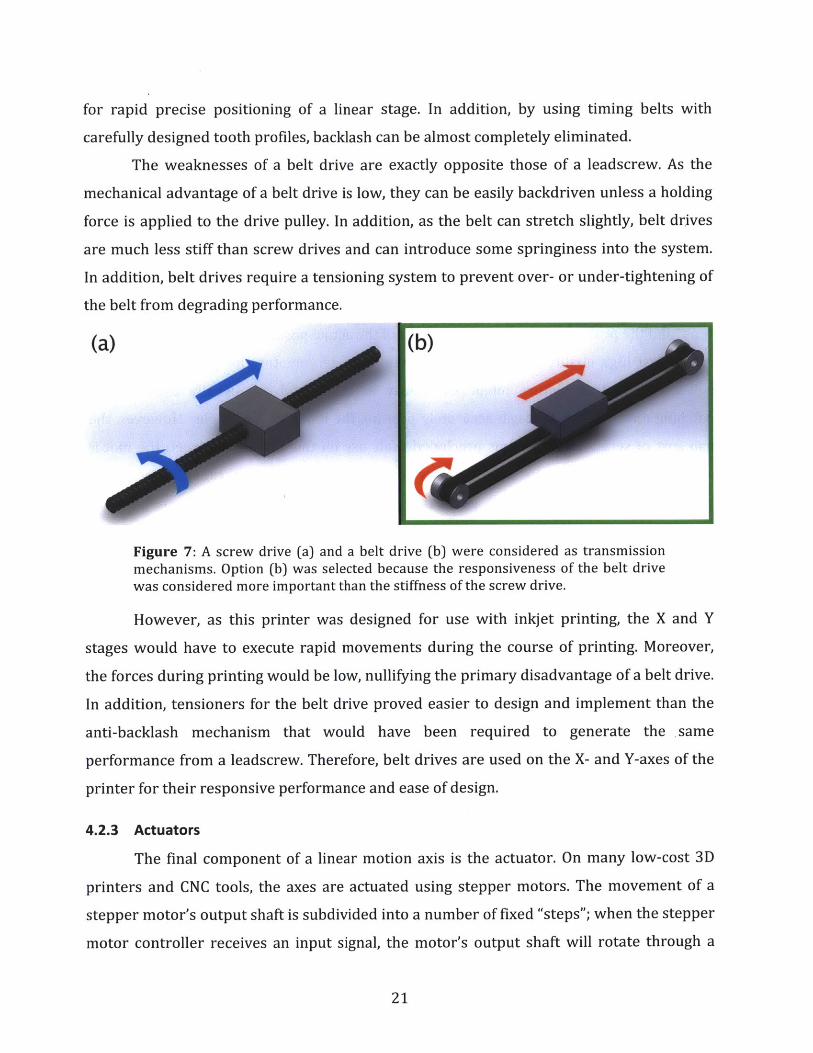
The weaknesses of a belt drive are exactly opposite those of a leadscrew. As the
mechanical advantage of a belt drive is low, they can be easily backdriven unless a holding
force is applied to the drive pulley. In addition, as the belt can stretch slightly, belt drives
are much less stiff than screw drives and can introduce some springiness into the system.
In addition, belt drives require a tensioning system to prevent over- or under-tightening of
the belt from degrading performance.
(a)
Figure 7: A screw drive (a) and a belt drive (b) were considered as transmissionmechanisms. Option (b) was selected because the responsiveness of the belt drivewas considered more important than the stiffness of the screw drive.
However, as this printer was designed for use with inkjet printing, the X and Y
stages would have to execute rapid movements during the course of printing. Moreover,
the forces during printing would be low, nullifying the primary disadvantage of a belt drive.
In addition, tensioners for the belt drive proved easier to design and implement than the
anti-backlash mechanism that would have been required to generate the same
performance from a leadscrew. Therefore, belt drives are used on the X- and Y-axes of the
printer for their responsive performance and ease of design.
4.2.3 Actuators
The final component of a linear motion axis is the actuator. On many low-cost 3D
printers and CNC tools, the axes are actuated using stepper motors. The movement of a
stepper motor's output shaft is subdivided into a number of fixed "steps"; when the stepper
motor controller receives an input signal, the motor's output shaft will rotate through a
21

fixed angle and then stop and hold that position. This feature makes it possible to use a
stepper motor in open-loop mode for controlling position without the need for sensors.
However, the number of steps per revolution is small, typically 200, so more precise
positioning applications may require a reducing transmission. An alternative method of
improving positioning resolution is to use a microstepping driver, which subdivides each
step of the motor into multiple smaller steps. One potential drawback with using stepper
motors in open-loop mode is positioning slip: if a sufficiently high load is applied to the
output of a stepper motor, the motor's shaft may stop rotating, causing the motor to "lose
steps" and the positioning system to lose track of the actual position of the motor's output.
Most high-quality motion control systems use servomotors for positioning. These
high-torque motors feature integrated rotary encoders and are usually used with a
matching motor driver that can accurately position the motor at any angle. However, the
high cost of servomotor systems precluded their use on this project: between the motor
and controller, a servomotor positioning system can easily cost several times the price of a
suitable stepper motor system. In particular, due to the relatively low torques required in
this system, appropriately sized stepper motors supply sufficient positioning resolution
and torque.
A compromise that addresses the above problem would be to use a standard DC
motor to actuate the axis, paired with a linear encoder to register position - in effect, a
scratch built servomotor. In addition, due to the low stiffness of a belt drive, the linear
encoder is useful for verifying the actual position of the carriage, a task that cannot be
performed using a rotary encoder attached to the motor's output shaft. However, non-
stepper motors usually require a gearbox or other transmission to generate sufficient
torque, thereby introducing backlash into the system and negatively affecting positioning
performance. Low-backlash gearboxes are available, but typically add significant cost to the
system. Additionally, a DC motor would require a control algorithm in order to perform the
necessary position and velocity control tasks for printing.
For this project, stepper motors were found to give the best positioning ability for
their cost. As servomotors were deemed too costly, the remaining decision was between
stepper motors and standard DC motors. The primary weakness of a stepper motor is the
potential for losing steps, but this weakness can be overcome by the addition of a linear
22

encoder, as would be used with a DC motor. The resulting combination is much easier to
control than a standard DC motor with encoder, as low-speed positioning can be effected
using open-loop positioning. In addition, open-loop velocity control can be achieved by
simply feeding step commands to the motor at a constant rate. Consequently, stepper
motors were chosen as actuators on this printer due to their low cost and ease of control.
23

5 Hardware Implementation
The following section covers specific design details of the printer's subsystems.
Section 5.1 provides an overview of the X- and Y-axes, followed by detailed descriptions in
Sections 5.2 and 5.3, respectively. The Z-axis design is presented in Sections 5.4 and 5.5.
Next, the printer's modular system is described in Section 5.6, and the print heads
presented in Section 5.7. Section 5.8 presents the electrical systems of the printer, and
Section 5.9 details the printer's structural frame and enclosure.
5.1 X- and Y-Axes Overview
The X-axis and Y-axis are arranged in a series configuration to move the printer's
carriage in a plane. In particular, the Y-axis carries the X-axis, which actuates the carriage,
as shown in Figure 8. Both axes use a timing belt drive for actuation and ride on linear ball
bearings carried on twin round shafts.
Figure 8: The Y-axis of the printer (blue) carries the X-axis of the printer (red),which in turn moves the carriage (green).
24
Given the functional requirements, the printer features stepper motors as the
actuators on all of its axes. Stepper motors are far and away the lowest-cost option, and are
capable of delivering the desired functionality. High-torque stepper motors drive the X- and
Y-axis belt drives directly, allowing the printer to execute the high-speed movements
required for inkjet printing. Each motor is paired with a Big Easy Stepper Driver from
SparkFun Electronics, which operates in 16x microstepping mode to provide a positioning
resolution better than 2000 DPI. Both the X-axis and the Y-axis feature 2mm pitch GT2
timing belt, which provide smooth engagement and low backlash.
In order to compensate for the possibility of missed steps, both the X- and Y-axes
feature linear incremental encoders from US Digital. The 500 lines-per-inch encoders are
used in quadrature mode, giving an effective sensing resolution of 2000 counts per inch.
These encoders measure the actual position of the load being moved, thereby allowing
detection of missed steps. As the encoders are a more reliable measure of the position of
the printer's carriage, they are also used to trigger the print heads during printing. Finally,
data from the encoders was used to compute acceleration trajectories for the X- and Y-axes,
allowing for smoother movement and more accurate positioning. This algorithm is
described in more detail in Section 6.
25

Figure 9: A view inside the printer, showing the X- and Y-axes.
26

5.2 X-Axis Details
Figure 10: The X-axis of the printer. The guide rail of the modular system is visiblebeneath the carriage (center).
The linear guide for the X-axis is a pair of 5/8" precision-ground hardened steel
shafts supported at each end by holes in aluminum box-beam extrusion. Two shafts are
required to constrain the carriage to a straight-line motion. To ensure that the shafts are
parallel, the support holes for the shafts were drilled and reamed through both pieces of
extrusion in a single machining operation. Aluminum clamps attached to the box-beam
extrusion prevent axial movement of the rods.
27

Figure 11: One of four end clamps of the X-axis guide rods. The clamps firmlysecure the guide rods and prevent them from shifting axially.
The carriage that carries the print heads is machined from a block of aluminum and
travels along these shafts on four flanged linear bearings. The design avoids overconstraint
because the bearings can move laterally during assembly, allowing their separation to be
matched to the separation between the guide shafts.
A 23Y-102D hybrid stepper motor from Anaheim Automation actuates the carriage
of the X-axis via a 2mm pitch GT2 belt drive. The motor is rigidly bolted to the box-beam
extrusion at one end of the axis. The other end features an idler pulley, whose position can
be adjusted to change the tension in the belt. The drive belt loops around the motor and
idler and is attached to the carriage with a belt clamp, thereby converting the rotary motion
of the motor to linear travel of the belt.
28

5.3 Y-Axis Details
Guide shafts
Figure 12: The Y-axis of the printer, with key components labeled. The steppermotor and the retaining plates at each end of the guide shafts are attached to theprinter's frame.
As on the X-axis, the load of the Y-axis is carried on four linear ball bearings riding
on a pair of 5/8" precision-ground hardened steel shafts. In this case, the load is the entire
X-axis and carriage assembly, providing a second degree of translation for the printer. One
pair of bearings is rigidly attached to the box-beam extrusion at the motor-carrying end of
the X-axis. The other pair of bearings is attached to the idler end of the X-axis with a pair of
flexures. The flexures allow the position of the bearings to shift slightly to account for
misalignment of the guide shafts or thermal expansion of the X-axis.
29

Figure 13: A CAD model of one end of the X-axis (left), showing the flexures(highlighted in yellow), and a photo of the flexures on the actual printer (right). Theflexures were cut from aluminum sheet on the waterjet and allow the Y-axisbearings to shift laterally to compensate for misalignment and thermal expansion,while still supporting the weight of the X-axis.
A pair of end plates supports each shaft of the Y-axis. The two end plates for each
shaft were drilled and reamed together to ensure the support holes were parallel.
Aluminum clamps bolted to the end plates constrain the shafts axially. As each shaft has its
own pair of end plates, the separation between the shafts is not fixed until they are bolted
to the frame. This feature allows for sequential assembly of the two motion axes, as the
shaft separation can be set to the length of the X-axis.
Owing to the large width of the X-axis, the Y-axis features two drive belts, one for
each guide rod. Each belt has its own tensioner and is clamped on to one end of the X-axis.
A "double shafted" 24Y-404D stepper motor from Anaheim Automation is used to
actuate both belts synchronously, ensuring that the X-axis is carried smoothly. The motor's
shaft extends out both sides of the case; each end connects to its corresponding belt drive
30

pulley via a helical beam coupling, which allows for misalignment between the motor and
the drive shafts. The motor and end plates of the Y-axis are attached to the structural frame
of the printer.
Figure 14: The double-shafted stepper motor used to actuate the Y-axis. Helicalbeam couplings are used to attach each end of the motor to its corresponding pulleydrive shaft.
5.4 Z-Axis Overview
In contrast to the X- and Y-axes, the Z-axis only needs to make infrequent small
movements: namely, each time a layer is finished, it must descend one layer in height,
typically a few thousandths of an inch or less. Accordingly, low movement speed is not a
concern. However, as it must support the weight of the build platform in the direction of
movement, stiffness and strength are of critical importance.
A lead screw drive provides exactly the required combination of features needed for
this task. The large mechanical advantage of the screw drive means even a modestly sized
motor will be able to move the weight of the build platform. Screw drives are non-
backdrivable, so the drive motor will not need to exert a large holding torque to maintain
31

the platform's position. The primary drawback of a leadscrew, the slow movement speed, is
mostly irrelevant in this application because the build platform is not required to translate
quickly or frequently. Finally, the backlash in the lead screw system is eliminated because
the weight of the build platform preloads the drive nut against the lead screw.
Many desktop 3D printers feature a cantilevered build platform that is actuated by a
single screw drive. While this design is adequate for small prints, its low stiffness makes it
unsuitable for larger printers. An examination of existing industrial printers reveals that
most feature two or more linear screw drives actuating the platform together, allowing
multiple-point support of the build platform. Due to the size and weight of the build
platform in this printer, three independent screw drives are used to control the Z-axis. The
use of additional screw drives provides more support for the platform, as well as the ability
to tilt the platform for leveling and calibration.
5.5 Z-Axis Details
Much like on the X- and Y-axes, the linear guide on each Z-axis screw drives is made
from a pair of 5/8-inch precision-ground hardened steel shafts. The end plates of each
screw drive were drilled and reamed in a single machining operation to ensure that the
guide shafts would be parallel. Clamps on the end plates hold the shafts in position.
As the screw drives move more slowly and less frequently than the X- and Y-axes,
their carriages ride on bronze guide bushings instead of linear ball bearings. These
bushings provide a low-cost and robust alternative to linear ball bearings. The guide
bushings are mounted in oversize holes and were glued into place on the carriage during
final assembly of each screw drive, ensuring alignment with the guide shafts.
32

End plates Leadscrew
Guide rails
Figure 15: A CAD model (left) and photo (right) of a single screw-drive unit fromthe Z-axis. The motor at the top a leadscrew, which translates the carriage up anddown. The screw drive mechanism is preloaded by the weight of the platform.
Each linear screw drive features a 23Y-002D stepper motor from Anaheim
Automation at its upper end. The motor drives a %"-10 acme leadscrew using a helical
beam coupling, which compensates for misalignment between the motor shaft and
leadscrew. A Teflon@ PTFE leadscrew nut is attached to the carriage, causing the carriage
to traverse linearly when the stepper motor rotates; the screw is preloaded by the weight
of the build platform, removing backlash from the system. A pair of needle roller bearings
at the upper end plate supports the weight on the leadscrew. Belleville washers apply a
preload force to the bearings, and the entire bearing and end plate assembly is secured
between two Acme nuts held in place by Loctite, as seen in Figure 16. As the lead screw
"hangs" by its top end, loading forces on the screw place it in tension rather than
compression, avoiding the potential for buckling.
33

Figure 16: A close-up photo (left) and labeled diagram (right) of the top end of oneof the Z-axis screw drives. The helical coupling compensates for misalignmentbetween the lead screw and the stepper motor, while the needle thrust bearingssupport the weight of the platform.
The reduction of the screw drive gives each Z-axis drive unit an effective resolution
of 2000 motor steps per inch of travel, even without microstepping. As a screw drive
increases the effective torque of the stepper motor and is non-backdrivable, it is unlikely
that the stepper motor would skip steps. Consequently, unlike the X-axis and Y-axis, the Z-
axis screw drives do not feature linear encoders. However, each motor features a rear shaft
for mounting rotary encoders if necessary.
Together, the three screw-drive units support the weight of the build platform. The
carriage of each unit features a precision steel ball, which rides on a pair of steel shafts on
the underside of the build platform. The combination of the three balls and three sets of
shafts forms a kinematic coupling, precisely and repeatably locating the build platform
relative to the screw-drive units. The platform is held in place by gravity. As a result, the
platform can be easily removed from the printer and returned to precisely the same
location. This feature potentially allows for mid-print inspections of printed parts, as well
as servicing and cleaning of the build platform without re-calibration of the Z-axis. In
34

addition, because the three screw-drive units are independent, they can also be used to
control the angle of tilt of the Z-axis. These extra degrees of freedom allow for automatic
platform leveling and calibration.
Figure 17: A top-down diagram of the build platform (left), along with a photo of
the ball-and-shafts coupling mechanism (right). The diagram shows the the pairedshafts (red) and precision balls (green) that form the kinematic coupling that joinsthe platform and the screw drive units. The platform has been made transparent inthis image for ease of understanding.
The build platform itself is made from a single piece of -inch thick piece of
aluminum. Aluminum was chosen due to its thermal stability and good strength-to-weight
ratio. In addition, it does not react chemically with most organic chemicals, making it
relatively easy to clean the build platform after printing.
One potential objection to the current design is the necessity of using three
independent motors to drive the three screws of the Z-axis. As only one degree of freedom
is required to control the vertical axis, using a single motor to drive all three screws would
be sufficient. Furthermore, synchronizing the screws using a belt or gear mechanism would
keep the Z-axis from becoming misaligned after initial calibration. However, belts or gears
35

would exert a radial force on the screws being driven. The radial loading would necessitate
a more complex design incorporating bearings to absorb the lateral forces in addition to
the axial forces exerted by the weight of the platform. Finally, the synchronization afforded
by a belt or gear drive can be emulated by driving all three screw drives in sync, a relatively
easy task as the leadscrew drives are powered by stepper motors.
5.6 Modular System
The printer features multiple print heads, allowing the use of a variety of materials
and print technologies to create objects. The printer's modular system serves to attach the
print heads to the printer carriage. In order to simplify development of individual print
head systems, each print head module can be easily removed from or reattached to the
printer, allowing for easy testing of individual print heads or combinations of print heads.
The modular system consists of a single piece of RLA-series dovetail optical rail
from Thorlabs attached to the carriage, and an optical rail carrier attached to each print
head module, as seen in Figure 18.
Figure 18: The optical rail (top) and carrier (bottom). The rail is attached to theunderside of the carriage, and the carriers are attached to the modules. This allowsthe modules to be attached and removed easily by adjusting the thumbscrew.
The optical rail is bolted to an aluminum box beam, which stiffens the rail and
serves as a transition between the rail and the carriage. Although the dovetail rail does not
provide exact kinematic constraint, it does provide a relatively stiff attachment point for
the print head modules. In addition, both the rails and the carriers are commercial off-the-
36

shelf components, which allows for a relatively simple design and short development time.
Furthermore, print head modules can be positioned at any location along the length of the
optical rail, allowing for print heads of differing widths to be mounted to the carriage
without wasting space.
Figure 19: Two modules on the printer. The optical rail is attached to the undersideof the aluminum box beam behind the module.
An alternative design features locator pins attached to each module; the pins
interface with holes machined into a flat plate attached to the carriage. The modules are
secured to the plate with a bolt, which provides a restraining force but does not locate the
module. This design provides near-exact kinematic constraint and requires fewer
expensive commercial off-the-shelf parts. However, the flat plate with mounting holes
would have to be carefully machined; in addition, the spacing of the modules is rigidly
37

fixed, which prevents the use of modules of differing sizes. This design would be a fairly
good choice for a lower-cost printer that features a smaller number of print heads.
5.7 Print Heads
Commercially available inkjet printers typically operate on one of two technologies:
thermal or piezoelectric. In thermal inkjet printing, each nozzle consists of a small resistor
quickly heated by a large electric current. The heat thus produced vaporizes a small
quantity of ink, producing a pressure pulse that ejects a droplet of ink from the nozzle. In
piezoelectric printing, each nozzle consists of a small piezoelectric actuator, which changes
shape in response to high voltage. A voltage pulse fed to the piezoelectric element causes it
to deform and produce a pulse of pressure in the ink, ejecting a droplet of ink from the
nozzle.
Figure 20: Close-up view of a piezoelectric print head from an Epson Workforce 30desktop inkjet printer. Each horizontal line is an individual piezoelectric element.
While piezoelectric print heads are more difficult to manufacture and hence are
more expensive than thermal print heads, they are compatible with a wider variety of
materials. In particular, as piezoelectric print heads do not heat the ink, they can be used
with thermally sensitive materials that would otherwise be unsuitable for use with thermal
inkjets. Accordingly, piezoelectric print heads were selected for this project because they
allowed for easy experimentation with a wide variety of print materials.
38

While industrial-scale piezoelectric print heads intended for use in poster printing
do exist, they tend to be expensive and difficult to acquire. In addition, each print head
features fewer nozzles and only supports a single color, complicating the process of
printing with multiple materials. Consequently, the print heads used in this printer are
harvested from commercially available Epson Workforce 30 inkjet printers. Inkjet printers
are widely available, and provide a source of low-cost, high precision piezoelectric print
heads. In addition, the ubiquity of color printing means that in almost all cases commercial
print heads support the use of multiple colors of ink, meaning that multiple materials can
be printed using a single print head. A custom Ethernet-enabled print head driver board
was used to control the print head, as seen in Figure 19.
5.8 Electronics and Wiring
As the printer has the ability to carry multiple print heads on the carriage, a large
number of cables and pipes must be routed through the motion system. These include the
motor power cables for the X-axis, encoder cables, power and communication lines for the
print head driver boards, and material feed lines. Cable carriers are used to organize these
wires and pipes, as well as to prevent them from being tangled within the printer's
mechanisms.
Two carriers are used to route electrical wires to the carriage. One carrier rests atop
a structural framing element and runs parallel to the Y-axis guide rods. The Y-axis encoder
wire and X-axis motor cables connect to their respective components immediately upon
exiting this carrier. The second carrier is supported above the X-axis by a pair of aluminum
shafts and is carried along with it when the Y-axis moves. This second carrier carries the
remaining power and control cables for the print heads, as well as the X-axis encoder wire.
Finally, a third cable carrier houses tubes that supply materials to the print heads.
This carrier is separate from the others both to reduce the overall size of each individual
carrier and to isolate the electrical systems from the effects of a leak in the materials feed
systems. In order to reach the carriage, this carrier is mounted in the carriage's plane of
motion, giving it two degrees of freedom as seen in Figure 21.
39

Figure 21: The three cable carriers in the printer. Cable carriers allow pipes andwires to be routed to the carriage in an orderly way without risk of entanglement orfatigue due to bending.
5.9 Frame and Enclosure
The structural frame of the printer supports the motion axes of the printer, houses
the electronics, and isolates the interior of the printer from the surrounding environment.
As the printer is intended for research, it is important that the frame and enclosure be
simple to assemble and modify, and also allow for easy inspection of the printer's
mechanical elements.
The structural frame of the printer is made from "80/20" T-slotted aluminum
beams, which provides the requisite structural strength. Due to the T-slots, printer
subsystems can be mounted at any point along the length of a structural framing element.
Attached to the frame of the printer are UV-blocking acrylic sheets. These sheets isolate the
interior of the printer from the environment, containing any volatiles or gases that are
emitted during the printing process. This isolation allows the use of materials with toxic or
unpleasant fumes without harming people nearby. As the panels also block ultraviolet rays,
40
UV-sensitive materials and photopolymers can be used as printing materials. In addition,
the panels also protect individuals nearby from the UV light source used to cure
photopolymers within the printer.
To improve access to the printer's internals, the upper portion of the printer's
enclosure is mounted on a separate section of aluminum framing and can swing upwards to
allow access to the printer's internals. Friction hinges connect the lid to the rest of the
printer and hold the lid in the open position. Like the rest of the frame, the lid is covered
with UV-blocking transparent acrylic panels, allowing for easy inspection of the printer's
internals while the lid is closed. A safety switch disengages when the lid is opened, keeping
the printer from moving or moving while the lid is open for inspection.
One potential concern when printing with potentially toxic materials, such as
photopolymers, is that volatile gases may leak out through the printer, endangering people
nearby. Two electric fans attached to the rear panel of the printer expel any gases or
particulates produced during the printing process through a pair of exhaust ducts, as seen
in Figure 22. The exhaust gases can then be vented to a chemical fume hood or captured in
filters. As the exhaust fans are sufficiently powerful to lower the pressure within the print
volume, outside air is pulled into the printer through any leaks, rather than exhaust gases
within the printer leaking out. This system simplifies the design of the enclosure, as not
every seam on the printer must be sealed perfectly.
Finally, the rear panel of the printer also features an electronics door, as seen in
Figure 22. Wires pass through the printer's enclosure via this door, allowing power and
control signals to be transmitted to subsystems within the printer. The door features seals
that conform to wires passing through, reducing leakage of air through the door.
41

Figure 22: A rendering of the rear of the printer (top), showing the location of theelectronics door (left) and exhaust fans (right). The electronics door can be adjustedto allow more wires to pass through the printer. The fans expel vapors producedwithin the printer to a fume hood. They also supply sufficient suction to draw air into the printer through leaks, rather than letting gases escape the printer.
42

6 Controls System Implementation
As stated previously, while the printer can be used with a variety of print
technologies, it has been designed with inkjet printing in mind. Inkjet printing requires the
print head be placed at equally spaced intervals in rapid succession. Rather than repeatedly
starting and stopping the print carriage's motion, the requirement can be more easily met
by moving the carriage at a constant velocity. In particular, constant velocity movement can
be obtained by feeding step commands to a stepper motor at regular intervals.
However, due to its discrete nature, a stepper motor rotating slowly may turn
unsteadily. The use of a microstepping stepper motor driver allows each step of the motor
to be further subdivided, allowing smoother movement. Consequently, microstepping
drivers are used on all axes of this printer.
A further problem arises if a stepper motor is immediately commanded to rotate at
a high speed. A stepper motor's torque decreases with increasing rotation speed, making
quick accelerations to high speeds difficult without losing steps. In extreme cases, the
motor's shaft may fail to rotate at all when step commands are fed too quickly to the
driving circuit. In addition, sudden accelerations and decelerations of the motion system
introduce impulses into the system, causing the printer to shake and the motors to lose
steps.
Input shaping can be used to improve the performance of motion systems. A simple
method involves linearly increasing the commanded velocity, thereby maintaining a
constant acceleration. However, this approach results in step changes in the motion
system's acceleration when starting, slowing, and stopping. These sudden changes in
acceleration introduce impulses into the motion system, causing vibrations. A secondary
effect of these impulses is to cause unsteadiness in the velocity of the carriage, betraying
the assumption of constant velocity required for inkjet printing.
Consequently, a more sophisticated motion profile is used in this printer. The profile
linearly increases the acceleration to its maximum value, then decreases it back to zero,
while accelerating to the desired speed. The resulting velocity profile is piecewise
quadratic, as seen in Figure 23.
43

Piecewise-Constant Jerk Motion Profle600
400
200
00 0.005 0.01 0.015 0.02 0.025 0.03
10
C
0 0.005 0.01 0.015 0.02 0.025 0.03
0.2
8 0.1
010 0.005 0.01 0.015 0.02 0.025 0.03
Time (s)
Figure 23: Acceleration, velocity, and position as a function of time using apiecewise-constant jerk profile, which linearly increases the system's acceleration toa maximum value then decreases it again.
As the stepper driver controls only the motors' positions and not their velocities, the
desired velocity profile must be converted into a series of positions, known as a motion
trajectory. One possibility is to use the printer's onboard processor to generate trajectories
on the fly. In theory, generating motion profiles in real-time allows for the optimum profile
for any given speed. However, the mathematics of profile generation may require complex
processor calculations, or may even be beyond the capabilities of small embedded
processors. An approximate method has been developed that are appropriate for use on
embedded processors, as shown in [12]. However, implementation of that method proved
difficult, even for the case of a linear velocity ramp. A linear acceleration ramp would
require further complex modifications to the algorithm.
An alternative approach is to precompute the motion trajectory. As the trajectory is
generated off-board, the computational load on the printer's embedded processor is
significantly reduced. A more powerful computer can be used to generate the trajectory,
allowing for the use of more complex input motion profiles. In addition, the task of writing
computer code for trajectory generation is vastly simplified, due to the increased
capabilities of off-board computers compared to the printer's embedded processor.
44

However, in order to support a variety of final speeds, a variety of motion profiles
must be generated, potentially consuming storage space on the onboard processor. An
alternative approach is to precompute only a small number of profiles, which are then
rescaled or modified on the fly.
This printer uses scaled precomputed ramps for input shaping. Given a maximum
allowable acceleration, a desired final velocity, and the acceleration profile shown in Figure
23, the distance required to accelerate to the desired velocity is
Sf = , (1)amax
where sf is the distance in microsteps (psteps), vf is the desired velocity in psteps/s, and
anax is the maximum acceleration in Isteps/s 2. As the stepper motor's velocity is controlled
by the delay between steps, a velocity profile can be generated by solving for the time at
which each step in the profile is reached, then taking the difference between timestamps.
The total time taken by the motion profile is given by
T = 2 vf (2)amax
where T is the time in seconds. As the acceleration increases and decreases linearly, the
system follows a piecewise-constant jerk profile, with the jerkj given by
j amax _ amax (3)T/2 vf
where j is the jerk in pisteps/s 3 and the formula for T has been substituted from (2). Using
this information, during the first half of the motion profile, between t = 0 and t = T/2, the
motion system follows the profile
s(ti) = 1jt13, (4)
45

where si is the microstep count at time ti, 0 < t2 < T/2. This equation can be inverted to
solve for the time ti of a given step during the first phase of the motion profile.
s2 (t 2 ) = -j(t 2 - T/2)3 + amax(t 2 - T/2)2 + L(t 2 - T/2) + s1 (T/2), (5)6 2 2
where s2 is the microstep count at time t2, T/2 < t2 < T, j is the jerk obtained in (3), and
si(T/2) is the value for si at ti = T/2, as obtained using (4). While this equation cannot be
directly inverted, it can be easily solved using a numerical solver to obtain the time t2 for a
given step position, demonstrating the advantages of precomputing a motion profile. The
sequence of timestamps for the steps in the first and second phases of the motion profile
can be combined to give a complete third-order positioning profile for accelerating to vf
with a maximum acceleration of amax. The difference between successive time stamps gives
the sequence of delays between steps of the stepper motor. Reversing the sequence of
delays yields the motion profile for decelerating from vf to 0.
To obtain motion profiles for accelerating to other speeds, first a profile is generated
for a chosen maximum velocity Vmax. This profile can then be rescaled for other desired final
velocities vf by multiplying each delay by Vdes/ v, with vf < Vmax. As profiles for final velocities
less than Vmax accelerate more slowly, the maximum allowable acceleration amax is never
exceeded. Conversely, this method does not accelerate the motion system as quickly as one
that always reaches the maximum acceleration amax. However, the profile does require a
fixed number of steps regardless of the final velocity, allowing for "acceleration zones" of
known size at the limits of the motion system's travel.
In this printer, the value for the maximum acceleration of 106 psteps/s 2 was selected
based upon experiments, as described in Appendix A. As the print heads used on the
printer have a maximum firing frequency of 10 kHz, a maximum movement speed vf
greater than this yields no improvement in print speed. However, because higher
movement speeds can still be useful for repositioning the carriage, vf was chosen to be
15000 isteps/s. The generated profile was loaded onto the computer's onboard processor,
46

which performs profile rescaling in real-time depending on the desired velocity. The
MATLAB code used for generating the profile can be found in Appendix B.
Tests were then run to assess the effects of the ramping profile on the motion
system's performance. The motion axes were accelerated to various speeds while the true
position of the carriage was measured using the system's encoders. The resulting data was
then compared with the system's behavior without the ramping profile. Figure 24 shows a
portion of a test where the X-axis carriage was commanded to move at 10000 [isteps/s.
8Effects of Input Shaping on X-axis Velocity
7
6
5-
3 -
2
1 -
0.--0.05 0.05
Tine (s)5
Figure 24: A comparison between the velocity of the X-axis without the rampingprofile (red -- line) and with it (blue solid line). The black dashed line shows thetarget speed of 4.6752 in/s (10000 psteps/s). During these experiments, theposition of the carriage was recorded using the X-axis encoder and used to calculatethe carriage's velocity. The resulting velocity values have been smoothed with amoving average filter with span 10.
It can be seen that the X-axis velocity exhibits significantly less overshoot and fewer
oscillations when using input shaping. The rise time is increased, but much of the increase
can be accounted for by the 0.045 seconds required to execute the ramping sequence when
47
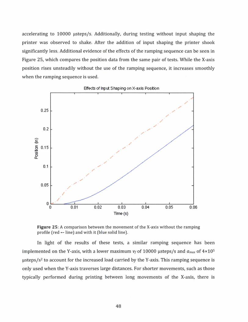
accelerating to 10000 psteps/s. Additionally, during testing without input shaping the
printer was observed to shake. After the addition of input shaping the printer shook
significantly less. Additional evidence of the effects of the ramping sequence can be seen in
Figure 25, which compares the position data from the same pair of tests. While the X-axis
position rises unsteadily without the use of the ramping sequence, it increases smoothly
when the ramping sequence is used.
Efiects of Input Shaping on X-axis Position
0.25
0.2
6I0.15
0.1 -
0.05 -
0 L0 0.01 0.02 0.03 0.04 0.05
Time (s)0.06
Figure 25: A comparison between the movementprofile (red -- line) and with it (blue solid line).
of the X-axis without the ramping
In light of the results of these tests, a similar ramping sequence has been
implemented on the Y-axis, with a lower maximum vf of 10000 psteps/s and amax of 4x10 5
[isteps/s 2 to account for the increased load carried by the Y-axis. This ramping sequence is
only used when the Y-axis traverses large distances. For shorter movements, such as those
typically performed during printing between long movements of the X-axis, there is
48

insufficient travel distance to execute the entire ramping sequence. Consequently, those
movements are performed at a low speed to reduce induced vibrations.
Due to the low movement speed of the Z-axis screw drives, trajectory generation is
not used in the control of those motors.
49

7 Results
Initial testing of the printer consisted of two parts: verification of the motion system,
and printing test objects. Experiments with the printer's motion system were used to
develop and test an appropriate input-shaping scheme for the X-axis and Y-axis, as
described in the Controls System section. Current experiments focus on using the
characterizing the printer's printing capabilities; testing is ongoing. Some preliminary
results follow below.
7.1 Bas-Relief Coin
This object was printed using a photopolymer known as "E-20", which was
developed in-house. The "coin" measures approximately 25mm in diameter, with a raised
ring bearing the text "SIGGRAPH 2013" and "TWO CENTS". A profile of comedian Stephen
Colbert, retrieved from [13], resides in the center of the coin. The "coin" was selected as a
test object due to its relatively small thickness and variety of feature types. In addition, it
can be printed without the use of support material, allowing testing without the
complications of aligning the print patterns of multiple materials. The object as initially
designed measured 100mm in diameter, and was reduced by a factor of 4 to expedite
testing. The coin consists of 600 layers and was printed at 600 DPI.
Figure 26: A test object as designed (left) and printed using the "E-20" polymer(right). The printed object measures approximately 25mm in diameter.
50

Overall, small details were reproduced reasonably well. In particular, fine details of
the profile such as the ear are visible, and the text on the rim of the coin is readable from a
couple feet away. A few faint horizontal lines can be seen across the surface of the coin;
these are artifacts produced by the nature of the printing process, as the print head is
swept side-to-side to build up the object. Similar lines can be seen on prints produced by
industrial printers. Key dimensions of the object as printed and as designed are compared
in Table 1.
Designed (mm) Scaled 25% mm Printed (mm)Diameter 100 25 24.88 ±.04Ring Width 10 2.5 2.63 ±.13Thickness 8 2 2.46 ±.07
Table 1: A comparison between the dimensions of the "coin" as designed and asprinted; the design was scaled by a factor of 4 prior to printing. Five measurementswere made of each dimension.
As printed, the diameter and ring width are fairly close to the scaled design values.
However, the thickness deviates from the scaled value by almost 25%. This discrepancy
can be explained by the use of an inaccurate layer thickness value during printing: As the
actual layer thickness was unknown, an estimate was substituted into the software for the
purposes of this test. Given that 600 layers were used during the printing, the actual layer
thickness is approximately 4.1x10⁻⁶ m.
An additional discrepancy can be seen in the feature in the center of Colbert's head.
The brain-shaped artifact occurred as a result of print head failure during the print. Prior
testing has revealed that during the course of printing, the nozzles of the print head
gradually cease to eject print material, in no discernable pattern. The most likely cause is
due to the viscosity of the print materials, which prevents them from flowing smoothly
through the feed lines of the printer. As the print heads used on this printer were salvaged
from desktop inkjet printers, they do not feature the extensive pressure and temperature
sensing and control systems typically found on industrial print heads intended for use with
unusual materials. Testing is currently underway to determine if the printer can be
configured to operate without these systems, or if a simplified design for them is possible.
51
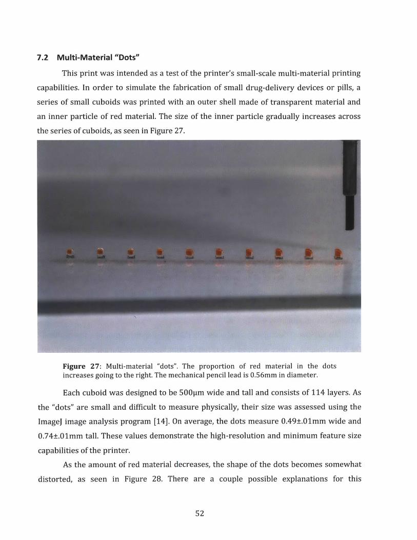
7.2 Multi-Material "Dots"
This print was intended as a test of the printer's small-scale multi-material printing
capabilities. In order to simulate the fabrication of small drug-delivery devices or pills, a
series of small cuboids was printed with an outer shell made of transparent material and
an inner particle of red material. The size of the inner particle gradually increases across
the series of cuboids, as seen in Figure 27.
Figure 27: Multi-material "dots". The proportion of red material in the dotsincreases going to the right. The mechanical pencil lead is 0.56mm in diameter.
Each cuboid was designed to be 500pm wide and tall and consists of 114 layers. As
the "dots" are small and difficult to measure physically, their size was assessed using the
ImageJ image analysis program [14]. On average, the dots measure 0.49±.01mm wide and
0.74±.01mm tall. These values demonstrate the high-resolution and minimum feature size
capabilities of the printer.
As the amount of red material decreases, the shape of the dots becomes somewhat
distorted, as seen in Figure 28. There are a couple possible explanations for this
52

phenomenon. First, the output spectrum of the UV LED used to cure the build materials
may not exactly match the sensitivity wavelength of the build materials, leading to
incomplete curing and causing the dots to have a distorted shape. Subsequent versions of
the UV curing module on the printer may feature alternative light sources with a broader
output spectrum in order to more reliably cure all build materials. Another possibility is
that the size of the jetted drops may be different between the colored and transparent
materials, leading to an uneven height in the final print. Nevertheless, these "dots" provide
a good demonstration of the printer's printing resolution and multi-material capabilities.
Figure 28: Photos showing the leftmost (left) and rightmost (right) multi-materialdots from Figure 27. The distortion in shape increases with the proportion ofcolored material.
53

8 Conclusions
The printer demonstrates a robust and low-cost design using stepper motors for
actuation. Commercial off-the-shelf components are used where possible, such as in the
framing and linear guide systems, reducing the cost and complexity of the system without
sacrificing performance. In particular, the print heads currently used on the printer are the
same as those used in commercial desktop inkjet printers, allowing for high-resolution,
multi-material performance in a small package at the fraction of the cost of industrial inkjet
print heads. Additionally, the modular nature of the print head mounting allows for the
independent development and testing of print heads.
As of the latest testing, the printer is capable of producing small high-resolution
multi-material objects, as seen in the results section. In addition, the printer is capable of
producing fine details, such as the lettering around the rim of the coin in Figure 26. These
features allow experimentation and development of additional applications for multi-
material printing.
8.1 Extensions / Future Work
Currently, the selection of print materials is limited, as development of materials is
still ongoing. In particular, many photopolymers that have been tested suffer from
excessive viscosity, so the print heads currently used on the printer are unable to eject
them. Other polymers do not cure completely under the current UV LED module. Alternate
curing modules may be developed to address this problem, either by using LEDs with
different frequencies or a broad-spectrum UV lamp.
In addition, the print head currently draws material from repurposed ink cartridges.
Consequently, the maximum print volume is restricted by the amount of material that can
be carried on the carriage in those cartridges. By attaching the cartridges to a constant-
level feed system, materials can be continuously supplied to the print head via external
tanks, allowing for longer prints and larger printed objects.
54

Bibliography
[1] Lipson, Hod and Melba Kurman. Fabricated: The New World of 3D Printing.Indianapolis: John Wiley and Sons, 2013.
[2] Wikimedia Foundation. 2013. 3D Printing.http://en.wikipedia.org/wiki/3D-printing (accessed March 14, 2013).
[3] Makerbot Industries. 2013. MakerBot Replicator' 2 Desktop 3D Printer.https://store.makerbot.com/replicator2.html (accessed March 10, 2013).
[4] RepRap project. 2013. RepRap - RepRapWiki.http://www.reprap.org/wiki/MainPage (accessed March 10, 2013).
[5] Parthy, Kai. 2013. Print wood now - with tree rings! LAYW00-D3 mm filament byKaipa - Thingiverse. http://www.thingiverse.com/thing:30552 (accessed March 10,2013).
[6] Formlabs. 2013. Formlabs - High Resolution Desktop 3D Printer. http://formlabs.com(accessed March 11, 2013).
[7] Stratasys Ltd. 2013. Objet500 Connex Multi-Material 3D Printer.http://www.stratasys.com/3d-printers/design-series/precision/objet-connex500(accessed April 17, 2013).
[8] Fab@Home Project. 2012. Main Page - Fab @ Home.http://fabathome.org/wiki2/wiki.html (accessed March 11, 2013).
[9] Fab@Home Project. 2011. Fab@Home:Gallery.http://fabathome.org/wiki2/fab-home-gallery.html (accessed February 20, 2013).
[10] Ultimaker. 2012. Ultimaker / the fast, easy to build, affordable 3D printer - 3D printingfor everyone! http://www.ultimaker.com (accessed April 10, 2013).
[11] Sogeva, S.A., Pascal Demaurux, and Marc-Oliver Demaurex. Devicefor the movementand positioning of an element in space. US Patent 4,976,582, filed September 6, 1989,and issued December 11, 1990.
[12] Austin, David. 2005. Generate stepper-motor speed profiles in real time.http://www.embedded.com//showArticle.jhtml?articlelD=56800129 (accessedApril 3, 2013).
[13] Glachant, Mathieu. 2011. Stephen Colbert's Peabody Award! bysyvwlch - Thingiverse.http://www.thingiverse.com/thing:9141 (accessed April 3, 2013).
55

[14] National Institute of Health. 2004. ImageJ. http://rsb.info.nih.gov/ij/ (accessed April3, 2013).
56

Appendix A
Measuring the Maximum Acceleration of the X-Axis
In order to produce the motion profiles described in theControls System section, a maximum value for the acceleration of the X-axis had to
be selected. Ideally, this value is based upon the actual maximum acceleration achievable
by the motion system. The holding torque of the stepper motor and the mass of the carriage
can be used to calculate a value for the acceleration, but this value is inaccurate as the
available torque of a stepper motor decreases with stepping frequency. In addition,
nonlinear effects such as friction from ball bearings and other components may be present
in the system, causing further deviation from estimated values. Thus, it was deemed easier
to determine the maximum acceleration experimentally rather than simply attempting to
calculate it.
The trajectory generation algorithm chosen for this project requires a chosen
maximum velocity, which in the final implementation is 15000 isteps/s. To measure the
maximum achievable resolution at this velocity, the X-axis stepper motor was commanded
to run at this speed without any ramping. The X-axis encoder was then used to measure the
resulting motion path of the carriage. The data was then fit to a quadratic polynomial,
under the assumption that the carriage could be modeled as a mass moving under uniform
acceleration. This analysis yielded a value for the acceleration of 1065.8 in/s 2 (R2 = .99949),
or approximately 2.28x10⁶ psteps/s 2. For a conservative estimate, this measured value was
approximately halved to yield 106 psteps/s 2, which was used in the calculations for
trajectory generation.
A similar technique was used to select the maximum acceleration value used on the
trajectory generation for the Y-axis.
57

Appendix B
MATLAB Code
The following code was used to generate the motion trajectories for the X- and Y-axes, asdescribed in Section 6.
% generates a precomputed ramp to vel with max acceleration accel% takes in vf in steps/sec, max acceleration in steps/sec/secfunction [t, s) = precompute2ndOrdRamp(vf, a-max)
s_f = ceil(v-f^2 / a max ); % final positionfprintf(1, 'total steps: %d\n', s_f);fprintf(1, 'about %g inches\n', s_f * 19 * (2/25.4) / 3200);
T = 2*vf/amax; % total time, secondsjerk = a_max^2 / vf; % calculate jerk
s_m = ceil(vf.^2 / (6*a-max) ); % calculate halfway positionv m = v f/2; % velocity at halfway time (half of final velocity)
% concave sections-pl = [O:s m]'; % motor moves one step at a time
% speed is controlled by time difference% between steps
t_pl = (6 *s-pl / jerk) .^(1/3); % time of each step in concave% section is just the appropriate% points on a cubic curve
% convex sections_p2 = [(s-m+1): sf]'; % remaining steps until final step positiont_p2 = zeros(length(sp2),1); % initialize time vector for convex
% velocity portion
s-m-true = v f.A2 / (6*a-max); % calculate non-truncated halfway position
%syms t2for i=1:length(s_p2)
a = -jerk/6; % t^b = amax/2; % t^
c =v m; % td = s_m_true-sp2(i); % co
tvals = roots([a, b, c, d]);
3 term (jerk)2 term (acceleration)term (velocity)nstant term (position)
% solve cubic for time associated% with position (d)
t_p2(i) = tvals(3)+T/2; % shift by halfway time
end
% comparison vectors with intended trajectorydt = 0.0001; % fine level time differencetc = [0:dt:t_pl(length(tpl))]; % time vector for comparisonsc = jerk/6 * tc.^3; % comparison position during first half
58

sc2 = sc(length(sc)) + v m*tc + amax/2 *tc.A2 - jerk/6*tc.A3;% comparison position during second half
t = [tpl; tp2]; % output associated timess = [s_pl; s_p2]; % output position
figure(3);% plot generated position with intended trajectory for comparisonplot(t, s, 'b.', tc, sc, 'r', tc+T/2, sc2, 'g');
end
59

Appendix C
Bill of Materials
This appendix lists the commercial off-the-shelf parts used in the construction of the
printer. In addition to these components, various thicknesses of aluminum plate and some
aluminum box beam were used to form structural elements of the printer.
FramePart # Part Name Vendor Quantity- 1515-Lite T-slotted extrusion, 24" long 80/20 Inc. 7- 1515-Lite T-slotted extrusion, 48" long 80/20 Inc. 8- 1515-Lite T-slotted extrusion, 36" long 80/20 Inc. 6- 1515-Lite T-slotted extrusion, 4.5" long 80/20 Inc. 4
47065T156 Aluminum Inch T-Slotted Framing System McMaster-Carr 4Concealed 90 Degree Connector, for 1-1/2"Extrusion
47065T51 Aluminum Inch T-Slotted Framing System Extended McMaster-Carr 290 Degree Bracket, Sngl, 4-Hole, for 1-1/2"
47065T178 Aluminum Inch T-Slotted Framing System 90 McMaster-Carr 16Degree Plate, Single, 5-Hole, for 1-1/2" Extrusion
47065T149 Double End-Feed Fastener, for 1-1/2" Aluminum McMaster-Carr 12Inch T-Slotted Framing System, packs of 4
6111K83 Swivel Leveling Mount Znc-Pltd STL, W/Pad, 3/8"-16 X McMaster-Carr 42" L Thrd, 2800#Load
CarriagePart # Part Name Vendor Quantity
Polycarbonate Belt clamp for single and double sidedA 6M51M090 belts SDP-SI 1
Steel Flange-Mount Linear Ball Bearing Square Flange,6483K64 5/8" Shaft Dia, 1-1/2 O'all Lg McMaster-Carr 4RLA2400 Imperial Dovetail Optical Rail, 24" Thorlabs 1
Extended Rail Carrier, 1" x 2", #8-32 Tapped Holes,RC2 1/4" Counterbore Thorlabs 8
60

X-AxisPart # Part Name Vendor Quantity
SparkFunROB-10735 Big Easy Driver Electronics 1
Anaheim
23Y102D-LW8 NEMA 23 double-shaft stepper motor, 175 oz-in Automation 1Hardened Precision Steel Shaft 5/8" Diameter, 24"
6061K151 Length McMaster-Carr 2
A 6A51- GT2 (2MM) Pitch, 19 Teeth, Aluminum Alloy Timing
019DF0908 Pulley SDP-Sl 2
A 6R51- GT2 (2mm) Pitch, 680 Teeth, 9mm (.354)lnch Wide
M680090 Neoprene Belt SDP-Sl 1
Polycarbonate Belt clamp for single and double sided
A 6M51M090 belts SDP-SI 1
Architectural Aluminum (Alloy 6063) Rect Tube, 1-1/2"
88935K111 X 3", 1/4" Wall Thk, 1' Length McMaster-Carr 1Steel Ball Bearing Flanged Open for 1/4" Shaft Dia,
6383K214 7/8" OD, 5/16" W McMaster-Carr 2
1327K113 Miniature 12L14 Drive Steel Shaft 1/4" OD, 3" Length McMaster-Carr 1
Steel Flange-Mount Linear Ball Bearing Square Flange,6483K64 5/8" Shaft Dia, 1-1/2 O'all Lg McMaster-Carr 2
Self-Aligning Linear Ball Bearing Closed, for 5/8" Shaft
6489K51 Diameter McMaster-Carr 1
External Retaining Ring for Linear Bearing for 1-1/8"9968K25 Bearing OD McMaster-Carr 2
EM1-0-500-N EM1 Transmissive Optical Encoder Module, 500 LPI US Digital 1
LIN-500-36-N LIN Transmissive Linear Strip, 500 LPI, No Index US Digital 1
61

Y-AxisPart # Part Name Vendor Quantity
SparkFunROB-10735 Big Easy Driver Electronics 1
Anaheim23Y202D-LW8 NEMA 23 double-shaft stepper motor, 262 oz-in Automation 1
Aluminum Helical Beam Clamp-on Shaft Coupling 1/4"6208K511 X 1/4" Bore, 1-1/2" Length, 1" OD McMaster-Carr 28632T139 D-Profile Shaft 1045 Steel, 1/4" OD, 12" Length McMaster-Carr 2A6A51- GT2 (2MM) Pitch, 19 Teeth, Aluminum Alloy Timing019DF0908 Pulley SDP-SI 4A6R51- GT2 (2mm) Pitch, 680 Teeth, 9mm (.354 inch) WideM680090 Neoprene Belt SDP-SI 2
Polycarbonate Belt clamp for single and double sidedA 6M51M090 belts SDP-SI 257155K304 Mini HI-Precision SS Ball Bearing - ABEC-5 Flanged McMaster-Carr 8
Open, 1/4" ID, 1/2" OD, 1/8" Width6061K151 Hardened Precision Steel Shaft 5/8" Diameter, 24" McMaster-Carr 2
Length4638K511 Zinc-Pltd STL, 1/8 Pipe Sz, Hex-Socket Plug McMaster-Carr 489015K18 Multipurpose Aluminum (Alloy 6061) .125" Thick, 12" McMaster-Carr 1
X 12"1327K113 Miniature 12L14 Drive Steel Shaft 1/4" OD, 3" Length McMaster-Carr 247065T149 Double End-Feed Fastener, for 1-1/2" Aluminum Inch McMaster-Carr 2
T-Slotted Framing System, packs of 4EM1-0-500-N EM1 Transmissive Optical Encoder Module, 500 LPI US Digital 1LIN-500-21-N LIN Transmissive Linear Strip, 500 LPI, No Index US Digital 1
62

Z-Stage (per screw drive unit; 3 units total)Part # Part Name Vendor Quantity
SparkFunROB-10735 Big Easy Driver Electronics 3
Anaheim23Y002D-LW8 NEMA 23 double-shaft stepper motor, 76 oz-in Automation 3
1018 Carbon Steel Precision ACME Threaded Rod 1/2"-99030A005 10 Sz, 1/10" Travel Distance/Turn, 3'L, RH Thread McMaster-Carr 3
Aluminum Helical Beam Clamp-on Shaft Coupling 1/2"6208K541 X 1/4" Bore, 1-1/4" Length, 1-1/4" OD McMaster-Carr 3
Hardened Precision Steel Shaft 5/8" Diameter, 24"6061K151 Length McMaster-Carr 6
Graphite SAE 841 Bronze Flange Bearing for 5/8" Shaft9440T41 Dia, 3/4" OD, 1" Length McMaster-Carr 3
Multipurpose Aluminum (Alloy 6061) Rect Tube 1/8"6546K412 Wall Thickness, 2" X 3", 3' Length McMaster-Carr 3
Cage Assembly for 1/2" Shaft Diameter, 15/16" GD5909K31 Steel Thrust Needle-Roller Bearing McMaster-Carr 6
.032" Thick Washer for 1/2" Shaft Diameter Steel5909K44 Thrust Needle-Roller Bearing McMaster-Carr 12
Plain Steel ACME 2G Hex Nut Right-Hand, 1/2"-1094815A107 ACME Size McMaster-Carr 6
High-Carbon Steel Belleville Disc Spring .505" ID,9712K74 1.000" OD, .035" Thick, packs of 12 McMaster-Carr 1
Zinc-Plated Steel Type A SAE Flat Washer 1/2" Screw90126A033 Size, 1-1/16" OD, .07"-.13" Thick, packs of 55 McMaster-Carr 1
Double End-Feed Fastener, for 1-1/2" Aluminum Inch47065T149 T-Slotted Framing System, packs of 4 McMaster-Carr 3
63

EnclosurePart # Part Name Vendor Quantity
Aluminum Inch T-Slotted Framing SystemDrop-in Fastener W/Spring-Loaded Ball, for 1-
47065T327 1/2" McMaster-Carr 216Spring Steel Triple-Wave Spring Washer 5/16"
90134A030 Screw Size, .45" OD, .01" Thick (pack of 50) McMaster-Carr 5Plain Steel Type A SAE Flat Washer 5/16"Screw Size, 11/16" OD, .05"-.08" Thick (pack
91083A030 of 192) McMaster-Carr 2Aluminum Metric T-Slotted Framing System Drop-in
5537T248 Fastener W/Rubber Handle, 4 mm Hex, for 40mm McMaster-Carr 6Alum Load-Rated Oval Pull Hndl with Holes Black, 4-
5190A21 9/16" Ctr-to-Ctr, 1124# Load Rating McMaster-Carr 4Plain Grade 2 Steel Extra-Wide Thin Hex Nut5/16"-18 Thread Size, 9/16" W, 13/64" H (pack
90502A030 of 100) McMaster-Carr 1Aluminum Inch T-Slotted Framing System Plate,
47065T212 Double, 4-Hole, for 1-1/2" Extrusion McMaster-Carr 2
64