design and fabrication guidelines - lennox …webmanuals.lennoxeurope.com/out of...
TRANSCRIPT

Page 1
DESIGN AND FABRICATION GUIDELINES
I–INTRODUCTION
Lennox split system condensing units and heat pumps (fourtons and under) match with line sets of varying lengths of upto 50 feet (linear). These applications offer quick and simpleinstallations that are trouble free if the line sets are properlyinstalled. On split commercial applications and residentialinstallations beyond 50 feet, special design considerationsmust be followed to assure satisfactory system performance.An improperly designed system could result in a serious lossof capacity or even compressor failure.
This manual does not include piping information for Zone-master systems. Refer to the Zonemaster installation instruc-tions for further information about the Zonemaster system.
The intent of this manual is to represent generally acceptedsafe engineering practices. Specifications and limits outlinedin this manual are subject to change. System design shouldconform to all codes, laws and regulations applying at the site atthe time of installation. In addition, the procedures and limitsoutlined in this manual do not supersede local, state or na-tional codes under any circumstances. If you have questionsor comments about any of this information, contact LennoxApplication (Technical Support) in Dallas, Texas.
II–GENERAL INFORMATION
Four prime considerations in designing refrigeration lines are:1) cost of tubing, refrigerant and installation;2) pressure drop in lines;3) oil return; and4) amount of refrigerant in the system.
Cost is an obvious consideration which dictates that thesmallest tubing possible be used that will result in a systemwith acceptable pressure drop.
Pressure drop is important from a performance standpoint.The following general statements point out the effects ofpressure drop in the various components of the refrigerationpiping system:
1) Pressure drop in the suction line reduces capacity and in-creases power consumption. For air conditioning systems, aone pound drop in the suction line reduces capacity approxi-mately one percent. A suction line pressure drop of up to 3psi(3% capacity loss) is generally acceptable. A higher pressuredrop may be necessary in some applications to achieve ade-quate velocity for oil return even though this will result inhigher capacity loss.
2) Pressure drop in the liquid line produces no significant ca-pacity loss as long as 100% liquid is delivered to the expansionvalve and the pressure available is adequate to produce the re-quired flow. Pressure drop due to lift must be added to the fric-tion losses to determine total pressure drop. At normal liquidtemperatures, R22 pressure drops 1/2 pound per foot of verti-cal liquid lift.
Oil return is a major consideration since some oil is continual-ly being circulated with the liquid refrigerant and separates inthe evaporator. Oil must be returned to the compressor by en-trainment with the refrigerant vapor. Minimum velocity mustbe 800 fpm (approximately) in horizontal runs, 1500 fpm(approximately) in vertical suction risers.
Subcooling should be at least 10�F leaving the outdoor unit.All Lennox equipment is designed so that the charge may beadjusted to provide at least 10�F subcooling. This will allow a30 to 35 pound drop in the liquid line (including pressure dropdue to friction loss and vertical lift).
Introduction Page 1. . . . . . . . . . . . . . . . . . . . . . . . . . . . . . . . . . . . . . . . . . . . . . . . . . . . . . . . . . . . . . . . . . . . . . . . . . . . . . . . . . . . . . . . . . . . General Information Page 1. . . . . . . . . . . . . . . . . . . . . . . . . . . . . . . . . . . . . . . . . . . . . . . . . . . . . . . . . . . . . . . . . . . . . . . . . . . . . . . . . . . . Limitations – Air Conditioning Systems Page 2. . . . . . . . . . . . . . . . . . . . . . . . . . . . . . . . . . . . . . . . . . . . . . . . . . . . . . . . . . . . . . . . . . Limitations – Heat Pump Systems Pages 2,3. . . . . . . . . . . . . . . . . . . . . . . . . . . . . . . . . . . . . . . . . . . . . . . . . . . . . . . . . . . . . . . . . . . . How To Design Piping Layout – R22 Systems Pages 3-5. . . . . . . . . . . . . . . . . . . . . . . . . . . . . . . . . . . . . . . . . . . . . . . . . . . . . . . . . .
Liquid Line Pages 3-5. . . . . . . . . . . . . . . . . . . . . . . . . . . . . . . . . . . . . . . . . . . . . . . . . . . . . . . . . . . . . . . . . . . . . . . . . . . . . . . . . . . . . . Layout and Design – Standard Systems Pages 3-5. . . . . . . . . . . . . . . . . . . . . . . . . . . . . . . . . . . . . . . . . . . . . . . . . . . . .
Suction Line Pages 5-10. . . . . . . . . . . . . . . . . . . . . . . . . . . . . . . . . . . . . . . . . . . . . . . . . . . . . . . . . . . . . . . . . . . . . . . . . . . . . . . . . . . . Layout and Design – Standard Systems Pages 7,8. . . . . . . . . . . . . . . . . . . . . . . . . . . . . . . . . . . . . . . . . . . . . . . . . . . . . Layout and Design – Two Speed Systems Pages 8,9. . . . . . . . . . . . . . . . . . . . . . . . . . . . . . . . . . . . . . . . . . . . . . . . . . . Layout and Design – Other Variable Capacity Systems (Hot Gas Bypass Systems) Pages 9,10. . . . . . . . . . . . .
Operation and Construction of Double Suction Risers Pages 9,10. . . . . . . . . . . . . . . . . . . . . . . . . . . . . . . . . Appendix: Reference Tables, Charts, Other Information Pages 11-21. . . . . . . . . . . . . . . . . . . . . . . . . . . . . . . . . . . . . . . . . . . . . . .
Table, Refrigerant Capacity in Copper Pipe Page 11. . . . . . . . . . . . . . . . . . . . . . . . . . . . . . . . . . . . . . . . . . . . . . . . . . . . . . . . . . . Table, Equivalent Length of Valves, Fittings Page 11. . . . . . . . . . . . . . . . . . . . . . . . . . . . . . . . . . . . . . . . . . . . . . . . . . . . . . . . . . . How To Charge By Subcooling Method Page 11. . . . . . . . . . . . . . . . . . . . . . . . . . . . . . . . . . . . . . . . . . . . . . . . . . . . . . . . . . . . . . Table, R22 Saturation Chart Page 12. . . . . . . . . . . . . . . . . . . . . . . . . . . . . . . . . . . . . . . . . . . . . . . . . . . . . . . . . . . . . . . . . . . . . . . . . Pump Down Control, Typical Wiring and Operating Sequence Page 13. . . . . . . . . . . . . . . . . . . . . . . . . . . . . . . . . . . . . . . . . Table, Low Ambient Cooling Controls Page 13. . . . . . . . . . . . . . . . . . . . . . . . . . . . . . . . . . . . . . . . . . . . . . . . . . . . . . . . . . . . . . . . Complex Liquid Line Sizing Pages 14,15. . . . . . . . . . . . . . . . . . . . . . . . . . . . . . . . . . . . . . . . . . . . . . . . . . . . . . . . . . . . . . . . . . . . . Complex Suction Line Sizing Pages 15,16. . . . . . . . . . . . . . . . . . . . . . . . . . . . . . . . . . . . . . . . . . . . . . . . . . . . . . . . . . . . . . . . . . . . Types of Expansion Devices Page 17. . . . . . . . . . . . . . . . . . . . . . . . . . . . . . . . . . . . . . . . . . . . . . . . . . . . . . . . . . . . . . . . . . . . . . . . . Piping Support Pages 18,19. . . . . . . . . . . . . . . . . . . . . . . . . . . . . . . . . . . . . . . . . . . . . . . . . . . . . . . . . . . . . . . . . . . . . . . . . . . . . . . . .
Glossary Pages 20,21. . . . . . . . . . . . . . . . . . . . . . . . . . . . . . . . . . . . . . . . . . . . . . . . . . . . . . . . . . . . . . . . . . . . . . . . . . . . . . . . . . . . . . . . . .
TABLE OF CONTENTS
MISCELLANEOUSOCTOBER 1993
#450119Corp.9351–L9Litho U.S.A.
1993 Lennox Industries Inc.

Page 2
One contributor to pressure loss in refrigerant lines is elbowsand fittings. Figure 1 shows how lines can be run to avoidpressure losses.
ÏÏÏÏÏÏÏÏÏÏÏÏÏÏÏÏÏÏÏÏÏ
FIGURE 1
ÏÏÏÏÏÏÏÏÏÏÏÏÏÏÏÏÏÏÏÏÏ RecommendedAcceptable
ELBOWS AND FITTINGS PRODUCE PRESSURE DROP. CARE-FULLY ROUTE LINES TO AVOID OBSTACLES IN PATH OF LINES.
Lower Pressure DropHigher Pressure Drop
In systems with lines over 50 feet and with suction line 7/8 inchO.D. or smaller, add 3 ounces of oil for each 10 feet of line over50 feet. For systems with 1-1/8 inch O.D. and larger suctionlines, add 4 ounces of oil for each 10 feet of line above 50 feet.When adding oil, use non-foaming refrigeration oil with a vis-cosity above 200 (e.g. 3G or 4G).
A major cause of compressor failure is liquid slugging. Due to theadditional refrigerant required to fill the lines, the likelihood ofslugging is greatly increased with lines over 50 feet in length. It isdesirable to use the smallest liquid line that will not result in re-frigerant flashing due to pressure drop. Table 1 (in Appendix)shows that each incremental increase in liquid line size results ina 40 to 50 percent increase in liquid to fill the line.
The liquid line must not directly contact the vapor line. If therefrigerant line plan results in a pressure drop of 20psi ormore, the liquid line should be insulated in all places where itpasses through an environment (such as an attic) which expe-riences temperatures higher than the subcooled refrigerant(approximately 105�F to 115�F liquid at 95�F ambient).
Refrigeration lines must not be buried in the ground unlessthey are insulated and waterproofed. Uninsulated copperlines buried in wet soil or under concrete can cause serious ca-pacity loss and erratic operation as well as early failure due tocorrosion. See Appendix for more information.
Systems with buried refrigerant lines can experience significantor total capacity loss if allowed to transmit heat to the surround-ings. In addition, buried lines are susceptible to corrosion whichcan shorten the life of the system. For this reason, buried linesmust rest inside a sealed, watertight, thermally insulated con-duit. The lines must not contact the soil for any reason and theconduit must be designed so it cannot collect and retain water.
Expansion valves are required on all commercial installationsand all residential (and multifamily) installations with linesover 50 feet linear.
In all installations with lines over 50 feet, use only hard copperrefrigeration tubing (clean and dry). Soft copper is prone tosagging in long horizontal runs. Elbows, Tees, Couplings andother joints should be made of wrought copper and elbowsshould be long radius. For leak free joints, properly clean tub-ing and fittings and use a brazing material with at least 3 to 5percent silver content (“sil-phos”). To prevent copper oxidesfrom forming inside copper tubing it is necessary to bleed drynitrogen through the tubing during the soldering process.
WARNINGFire Hazard. Never bleed oxygen through lines whensoldering joints. Oxygen burning in the presence ofoil can cause damage, personal injury or death.
WARNINGExplosion Hazard. Never use oxygen in refriger-ant lines. Oxygen in contact with oil creates anexplosive mixture which can cause damage, per-sonal injury or death.
WARNINGExplosion Hazard. Always use a regulator on nitro-gen bottle. Never connect bottle directly to gaugesor hoses without first regulating output. Hoses,gauges and or refrigerant lines could burst underpressure causing damage, personal injury or death.
III–LIMITATIONS FOR A/C SYSTEMS
Lennox line sets may be used up to 50 feet linear length (notincluding equivalent length of fittings). Lines over 50 feet upto 150 feet linear should be sized in accordance with section V.
Applications with less than 50 linear feet of refrigerant linemay use RFC metering devices on approved matchups aslisted in Lennox’ Engineering Handbook. Plans with less than50 linear feet of line may also use Lennox pre-fabricated linesets if available as listed in Lennox’ Engineering Handbook.
Maximum suction lift must not exceed 150 linear feet andmaximum liquid lift must not exceed 50 linear feet.
When line lengths exceed 50 feet, a liquid line solenoid shouldbe installed at the evaporator coil. If the compressor is notequipped with a crankcase heater, one must be added. In addi-tion, only expansion valves may be used (RFC and cap-tubeexpansion devices are not acceptable). In applications wherethe lines exceed 75 feet, the solenoid valve should be installedwith a non-recycling pump-down control. See appendix formore information and typical wiring.
Line lengths over 150 feet linear are not recommended. ContactLennox Application Department for engineering assistance.
In applications where cooling operation below 50�F is antici-pated and an economizer is not being used, low ambient(head pressure) controls must be installed. See Low ambientsection in Appendix.
IV–LIMITATIONS FOR HEAT PUMP SYSTEMS
Lennox line sets may be used up to 50 feet linear length (does notinclude equivalent length of fittings). Lines over 50 feet and up to100 feet linear should be sized in accordance with section V.
In applications up to 50 feet linear, either expansion valve orRFC metering may be used on approved system matchups aslisted in Lennox’ Engineering Handbook. But, when the linesexceed 50 feet, an expansion valve (in the indoor unit) and anaccumulator (in the outdoor unit) are both required. Expan-sion valve (in the indoor unit) and accumulator should beused in all commercial installations regardless of line length.Most Lennox equipment is equipped with a factory installedaccumulator. Never add a second accumulator. If an accumu-lator is not supplied and one must be added, the accumulatormust be properly sized and must be located in the suction linebetween the reversing valve and the compressor. In addition,when lines exceed 50 feet, a compressor crankcase heatermust be added to the compressor if not factory supplied.

Page 3
If heat pump refrigerant lines must exceed 100 feet, contactLennox Application Department for further assistance. Thisapplication is not recommended and should be avoided.Never install a liquid line filter drier in addition to factoryinstalled driers due to risk of excess pressure drop and risk ofimproper installation. Some Lennox heat pump units are fac-tory equipped with a liquid line filter drier with internal checkvalve. If a liquid line filter drier must be installed in a heatpump system make sure that refrigerant can only flow oneway through the device.
Special consideration must be given to heat pump systemswhen there is a difference in elevation between the outdoorand indoor units. Due to the reversal of refrigerant flow fromheating to cooling cycle, there is always a liquid and suctionlift to consider when sizing the refrigerant lines.
Maximum liquid lift should not exceed 50 linear feet (due tothe static pressure drop of 25psi). Additional pressure dropdue to friction will result in total pressure drop approachingthe 30psi maximum that could produce flashing.
Likewise, maximum suction lift must not exceed 50 feet due tolimitations placed on the liquid line. (When refrigerant flow isreversed, a liquid drop will become a liquid lift). The vapor linemust be sized as a suction riser with adequate velocity for oilreturn if there is any difference in elevation between the in-door and outdoor units.
In applications where cooling operation below 50�F is antici-pated and an economizer is not being used, low ambient(head pressure) controls must be installed.
Solenoid valves are uni-directional devices. Since solenoidvalves are uni-directional, they are seldom used on heat pumpsystems. If used, they require a check valve to bypass refriger-ant around the solenoid during the heating cycle. Never installa pump-down cycle on a heat pump system.
V–PIPE SIZING, LINE LAYOUT AND DESIGN
(A/C and Heat Pump Systems)
The first step in the design of a piping system is to layout theentire system (i.e. relative location of the condensing unitand the evaporator, length of each segment of the piping sys-tem, length of suction risers and liquid risers etc...) Start bymaking a sketch of the system including lengths of pipe,number of elbows, tees, valves, and any other irregular pip-ing and fittings needed. This information will be used to de-termine total “equivalent” length for calculating pressuredrop due to friction.
The same methods apply to both A/C and heat pump systems.A suction line sized to produce adequate velocity for oil entrain-ment and pressure drop with minimum capacity reduction willfunction properly as a hot gas discharge line during a heatingcycle. Also, if there is a vertical difference in height between theoutdoor and indoor units, there is always a vapor and liquid liftto consider in sizing due to the reversal of refrigerant flow.
A–Liquid Line Design
Considerations
The purpose of the liquid line is to convey a full column of100% liquid from the condenser to the metering device at theevaporator without flashing. The amount of liquid line pres-sure drop which can be tolerated is dependent on the number
of degrees of liquid subcooling leaving the condenser and thesaturated condensing temperature. If the condensing temper-ature and subcooling are known, the maximum allowablepressure drop can be calculated.
Lennox equipment is designed to hold a charge allowing 10�Fsubcooling at 95�F ambient. High efficiency equipment fivetons capacity and under typically operates at a saturated con-densing temperature of 115�F, (245psi) (see footnote 1). Equip-ment above five tons capacity typically operates at a saturatedcondensing temperature of 125�F, (280psi) (footnote 1).
Maximum Allowable Pressure Drop, Example 1
A high efficiency unit operating at 10�F subcooling and 115�F(245psi) condensing temperature, find the maximum allow-able pressure drop in the liquid line. Refer to the pressure/temperature chart (figure 16) in the appendix. 115�F condens-ing temperature minus 10�F subcooling equals 105�F sub-cooled liquid temperature (212psi - see footnote 2). 245psicondensing pressure minus 212psi subcooled pressureequals 33psi. The maximum allowable pressure drop is 33psi.
Maximum Allowable Pressure Drop, Example 1
A mid efficiency unit operating at 10�F subcooling and 125�F(280psi) condensing temperature, find the maximum allow-able pressure drop in the liquid line. Refer to the pressure/temperature chart (figure 16) in the appendix. 125�F condens-ing temperature minus 10�F subcooling equals 115�F sub-cooled liquid temperature (245psi - see footnote 2). 280psicondensing pressure minus 245psi subcooled pressureequals 35psi. The maximum allowable pressure drop is 35psi.
Two factors must be considered when sizing liquid lines:
Pressure Drop in Lines
First, the pressure drop through the liquid line is not especial-ly critical provided that 100% liquid is available entering theexpansion device. For the most part, the generation of flashgas will be determined by the amount of pressure drop in theliquid line. To calculate total pressure drop in liquid lines, thefollowing must be determined then added together:1) Pressure drop due to friction in pipe (figure 2), fittings andfield installed accessories such as a drier, solenoid valve orother devices (table 1). The pressure drop due to friction isusually smaller than pressure drop due to lift but must be con-sidered. The pressure drop ratings of field installed devices isusually supplied by the manufacturer of the device andshould be used if available.2) Pressure drop due to vertical liquid lift (1/2 pound per foot)is usually large and may be a limiting factor in the ultimate de-sign of the system.
Pressure Across Expansion Device and Distributor
Next, the pressure entering the expansion device must be suf-ficient to produce the required flow through the expansion de-vice. A pressure drop of 100 psi across the expansion valveand distributor is necessary to produce full refrigerant flow atrated capacity. Therefore, it is necessary for liquid refrigerant(free of flash gas) to be delivered to the expansion valve at aminimum of 175 psi.
Footnote 1 – The temperature listed here is an arbitrary number chosen to represent summer operating conditions. Thecondensing temperature at summer operating conditions is used to calculate maximum allowable pressure drop. Thisnumber may vary with regional climate.Footnote 2 – This is the pressure below which subcooled liquid will begin to form flash gas.

Page 4
REFRIGERANT-22 LIQUID LINE PRESSURE DROP/VELOCITYAt 45�F Evaporating Temperature and 125�F Condensing Temperature
30
25
20
15
10
9
8
7
6
5
4
3
2
1.5
1.0
.9
.8
.7
10 9 8 7 6 5 4 3 2 1.5 1.0 .9 .8 .7 .6 .5 .4 .3 .2
R22 LIQUID LINE PRESSURE DROP (lbs./100 Feet)
CO
OLIN
G C
APA
CIT
Y (
TO
NS
)
30
25
20
15
10
9
8
7
6
5
4
3
2
1.5
1.0
.9
.8
.7
CO
OLIN
G C
APA
CIT
Y (
TO
NS
)
10 9 8 7 6 5 4 3 2 1.5 1.0 .9 .8 .7 .6 .5 .4 .3 .2R22 LIQUID LINE PRESSURE DROP (lbs./100 Feet)
NOTE—Shaded area denotes unacceptable velocity range.
FIGURE 2
12.5
To use this chart, first find capacity (tons) on left side of chart. To find pipe size, proceed right to smallest pipe size. Pressure drop (verticalline) and velocity (diagonal lines) can then be determined for the pipe size selected. For example, for 10 ton unit, select 5/8 in. O.D. line.
EXAMPLE:10 TON UNIT 5/8 IN. O.D. LINE 4.25PSI DROP PER 100 FEET 275 FPM VELOCITY
40 30 20 15
40 30 20 15
Sizing Procedure – First ExampleSimple System
Given: 10 ton (single speed) condensing unit on ground levelwith a 10 ton evaporator on the third level above ground and atotal of 96 feet (linear) of piping. Unit is charged with 10�F sub-cooling at 125�F condensing temperature (280 psi R22 liquid).See figure 3.
Find: Select tube size from figure 2.
Figure 2 illustrates the relationship between liquid line sizing,pressure drop per 100 feet, velocity range and tonnage. Whenusing liquid line solenoid valves, velocities should not exceed300 fpm to avoid liquid hammer when closing. Enter figure 2from left and extend to the right to the smallest tube size thatwill not exceed 300 fpm velocity.

Page 5
10 TONCONDENSING
UNIT
10 TONEVAPORATOR
53 FT.
3 FT. 40 FT.
GIVEN; 10 TON EVAPORATOR10 TON CONDENSING UNITWITH 10�F SUBCOOLING at 125�FLENGTH OF LINE –– 96 FT.
FIND; LIQUID LINE SIZE
LIQUID LINE SIZING EXAMPLE
FIGURE 3
FILTER/DRIER
4.25 psi100ft.
x 98ft. = 4.17psi
ANSWER; 5/8” O.D. COPPER TUBING CAN BE USED. PRESSURE LOSS DOES NOT EX-CEED MAXIMUM ALLOWABLE PRESSURE DROP (6�F TO 7�F SUBCOOLING WILL BEAVAILABLE AT THE EXPANSION VALVE) AND VELOCITY IS ACCEPTABLE.
SELECT A PROPOSED TUBINGSIZE: 5/8in. COPPER
SOLUTION: PRESSURE DROP CANNOT EXCEED35 psi.
TOTAL PRESSURE DROP=TOTAL FRICTION LOSSES + LIFT LOSSES + FILTER/DRIER
TOTAL EQUIVALENT LENGTH = LINEAR LENGTH + EQUIVALENT LENGTH OF FITTINGS
TWO 90� LONG RADIUS ELBOWS @ 5/8in. O.D. = 1ft. EQUIV. FT. EA.
TOTAL EQUIVALENT LENGTH = 98ft.
TOTAL FRICTION LOSSES =
LIFT LOSSES = 40ft. x 1/2psi per foot = 20psi
TOTAL PRESSURE DROP = 20 psi + 4.17 psi + 1 psi = 25.17 psi
FILTER DROP = 1 psi (by manufacturer)
Solution: For a 10 ton system, 5/8 inch O.D. line with 4.25 psiper 100 feet drop is selected. Now, calculate pressure drop dueto friction and liquid lift to determine if this is a good selection.
The pressure lost to two elbows must be added to the equa-tion. The total friction drop for 96 feet of 5/8 inch O.D. pipe plus(from table 2) 1 equivalent foot per elbow = 98 equivalent feet.
Figure 2 shows that, in a 10 ton system, we can expect 4.25psi drop per 100 feet of 5/8 inch O.D. copper. When we mul-tiply 4.25/100 by 98 equivalent feet, we see that the totalfriction loss is 4.17 psi.
Now, we must add the pressure drop for vertical lift. R22 pres-sure drop is 1/2 psi per foot of vertical lift. When multiplied by40 feet vertical lift we find that pressure drop due to lift = 20 psi.
Finally, we have added a filter drier to the liquid line which has1psi drop (this number provided by manufacturer).
Add the three components of pressure drop together to findthat the total pressure drop in this 5/8 inch line = 25.17 psi.
Now, by comparing 25.17 psi to our maximum allowable pres-sure drop we find that this setup falls well within the accept-able range. The 5/8 inch line, therefore, is a good selection be-cause it is well below the maximum allowable pressure drop,is in a satisfactory velocity range, uses minimum refrigerantand provides sufficient pressure at the expansion valve.
First ExampleAlternative Pipe Size
Suppose 3/4 inch O.D. line with 1.6 psi drop per 100 feet hadbeen selected. The total equivalent length is computed by ad-ding the linear length (96 ft.) plus the equivalent length of thefittings (from table 2, two 90� ells at 1.25 ft. each). The totalequivalent length is 98.5 feet. The total friction drop wouldhave been 1.6/100 multiplied by 98.5 = 1.57 psi. When the pres-sure drop due to lift (20 psi) and the filter drier (1 psi) are addedwe find that the total pressure drop for 3/4 inch line = 22.57 psi.
Yet, 3/4 inch line is a less desirable choice. Why?
10 TONCONDENSING
UNIT
10 TONEVAPORATOR
53 FT.
3 FT. 40 FT.
GIVEN; 10 TON EVAPORATOR10 TON CONDENSING UNITWITH 10�F SUBCOOLING at 125�FLENGTH OF LINE –– 96 FT.
FIND; LIQUID LINE SIZE
LIQUID LINE SIZING EXAMPLE
FIGURE 4
FILTER/DRIER
1.6 psi100ft.
x 98.5 ft. = 1.57 psi
ANSWER; 3/4” O.D. COPPER TUBING CAN BE USED BECAUSE PRESSURE DROP ANDVELOCITY FALL WITHIN AN ACCEPTABLE RANGE. BUT 3/4 INCH LINE IS LESS DESIR-ABLE BECAUSE:1) A SMALLER LINE WITH ACCEPTABLE PRESSURE DROP AND VELOCITY IS AVAIL-ABLE (5/8 INCH) AND,2) THE LARGER (3/4 INCH) LINE WILL REQUIRE MORE REFRIGERANT IN THE SYSTEM.
SELECT A PROPOSED TUBING SIZE: FOR A 10 TON SYSTEM, 3/4 in. COPPER
SOLUTION: PRESSURE DROP CANNOTEXCEED 35 psi.
TOTAL PRESSURE DROP=TOTAL FRICTION LOSSES + LIFT LOSSES + FILTER/DRIER
TOTAL EQUIVALENT LENGTH = LINEAR LENGTH + EQUIVALENT LENGTH OF FITTINGS
TWO 90� LONG RADIUS ELBOWS @ 3/4 in. O.D. = 1.25 ft. EQUIV. FT. EA.
TOTAL EQUIVALENT LENGTH = 98.5 ft.
TOTAL FRICTION LOSSES =
LIFT LOSSES = 40ft. x 1/2psi per foot = 20 psi
TOTAL PRESSURE DROP = 20 psi + 1 psi + 1.57 psi = 22.57 psi
FILTER DROP = 1 psi (by manufacturer)
The difference in pressure drop between 5/8 inch line and 3/4inch line is only 2.35 psi. But, the larger line adds 5.5lbs. morerefrigerant into the system (see table 1). The risk of refrigerantslugging is increased and the smaller line will be less costly.The smaller line should be used.
B–Suction Line Design
PrinciplesThe purpose of the suction line is the return of refrigerant va-por and oil from the evaporator to the compressor. The sizingof vertical risers is extremely important. Movement of oildroplets up the inner surface of the tubing is dependant on themass velocity of the gas at the wall surface.The larger the pipe the greater the velocity required at the cen-ter of the pipe to maintain a given velocity at the wall surface.
Suction line design is critical. The design must minimize pres-sure loss to achieve maximum unit efficiency and yet provideadequate oil return to the compressor under all conditions.
Because oil separates from the refrigerant in the evaporator, thesuction velocity must be adequate to sweep the oil along. Hori-zontal suction lines require a minimum of 800 fpm velocity foroil entrainment. Suction risers require 1200 fpm minimum andpreferably1500 fpm regardless of the length of the riser.
Figure 5 illustrates the relationship between suction line sizing,pressure drop per 100 feet, velocity and cooling tonnage. Thischart is used to determine suction line pressure drop which canthen be used to determine suction line capacity loss. This chartcan also be used to determine suction line velocity to assure oilreturn to the compressor.
Vertical lift does not significantly affect pressure drop. However,systems will lose approximately 1% capacity for every pound ofpressure drop due to friction in the suction line. This “1%” factoris used to estimate the capacity loss of refrigerant lines. To usethe “1%” factor, first you must use figure 5 to estimate the pres-sure drop in the “total equivalent length” of the lines you choose.

Page 6
REFRIGERANT-22 SUCTION LINE PRESSURE DROP/VELOCITY PER 100ft. OF LINEAt 45�F Evaporating Temperature and 125�F Condensing Temperature
30
25
20
15
10
9
8
7
6
5
4
3
2
1.5
1.0
.9
.8
.7
10 9 8 7 6 5 4 3 2 1.5 1.0.9 .8 .7 .6 .5 .4 .3 .2R22 SUCTION LINE PRESSURE DROP (lbs./100 Feet)
CO
OLIN
G C
APA
CIT
Y (
TO
NS
)
30
25
20
15
10
9
8
7
6
5
4
3
2
1.5
1.0
.9
.8
.7
CO
OLIN
G C
APA
CIT
Y (
TO
NS
)
10 9 8 7 6 5 4 3 2 1.5 1.0.9 .8 .7 .6 .5 .4 .3 .2
R22 SUCTION LINE PRESSURE DROP (lbs./100 Feet)
NOTE—Shaded area denotes unacceptable velocity range.
FIGURE 5
40 30 20 15
40 30 20 15
EXAMPLE: 10 TON UNIT1-3/8 IN. O.D. LINE3.3 PSI DROP PER 100 FEET2400 FPM VELOCITY
12.512.5
To use this chart, first find capacity (tons) on left side of chart. To find pipe size, proceed right to smallest pipe size. Pressure drop (verticalline) and velocity (diagonal lines) can then be determined for the pipe size selected. For example, for 10 ton unit, select 1-3/8 in. O.D. line.
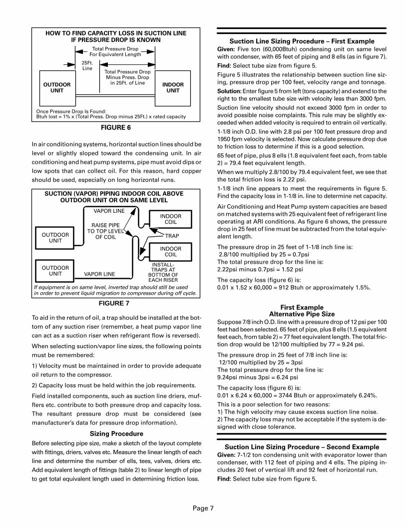
The (Engineering Handbook) capacity ratings of Lennox splitsystem equipment show the capacity when matched with aparticular indoor coil and 25 ft. of refrigerant line. These ca-pacity ratings have the loss for a 25ft. refrigerant line alreadydeducted. When you use this manual to estimate the capacityloss due to friction, you must calculate the pressure drop ofthe entire refrigerant line then subtract the pressure drop of a25ft. line. See figure 6. Remember, the objective is to hold re-
frigerant line capacity loss to a minimum.
Considerations
When an evaporator is located above or on the same level asthe condensing unit, the suction line must rise to the top of theevaporator. See figure 7. This helps prevent liquid from mi-grating to the compressor during the off cycle. Traps shouldalso be installed at the bottom of all vertical risers.
Page 7
OUTDOORUNIT
INDOORUNIT
HOW TO FIND CAPACITY LOSS IN SUCTION LINEIF PRESSURE DROP IS KNOWN
Total Pressure DropFor Equivalent Length
25Ft.Line
Once Pressure Drop Is Found:Btuh lost = 1% x (Total Press. Drop minus 25Ft.) x rated capacity
FIGURE 6
Total Pressure DropMinus Press. Drop
in 25Ft. of Line
In air conditioning systems, horizontal suction lines should belevel or slightly sloped toward the condensing unit. In airconditioning and heat pump systems, pipe must avoid dips orlow spots that can collect oil. For this reason, hard coppershould be used, especially on long horizontal runs.
OUTDOORUNIT
INDOORCOIL
SUCTION (VAPOR) PIPING INDOOR COIL ABOVEOUTDOOR UNIT OR ON SAME LEVEL
FIGURE 7
OUTDOORUNIT
INDOORCOIL
VAPOR LINE
VAPOR LINE
If equipment is on same level, inverted trap should still be usedin order to prevent liquid migration to compressor during off cycle.
TRAP
RAISE PIPETO TOP LEVEL
OF COIL
INSTALL-TRAPS AT
BOTTOM OFEACH RISER
To aid in the return of oil, a trap should be installed at the bot-tom of any suction riser (remember, a heat pump vapor linecan act as a suction riser when refrigerant flow is reversed).
When selecting suction/vapor line sizes, the following pointsmust be remembered:
1) Velocity must be maintained in order to provide adequateoil return to the compressor.
2) Capacity loss must be held within the job requirements.
Field installed components, such as suction line driers, muf-flers etc. contribute to both pressure drop and capacity loss.The resultant pressure drop must be considered (seemanufacturer’s data for pressure drop information).
Sizing Procedure
Before selecting pipe size, make a sketch of the layout completewith fittings, driers, valves etc. Measure the linear length of eachline and determine the number of ells, tees, valves, driers etc.Add equivalent length of fittings (table 2) to linear length of pipeto get total equivalent length used in determining friction loss.
Suction Line Sizing Procedure – First Example
Given: Five ton (60,000Btuh) condensing unit on same levelwith condenser, with 65 feet of piping and 8 ells (as in figure 7).
Find: Select tube size from figure 5.
Figure 5 illustrates the relationship between suction line siz-ing, pressure drop per 100 feet, velocity range and tonnage.
Solution: Enter figure 5 from left (tons capacity) and extend to theright to the smallest tube size with velocity less than 3000 fpm.
Suction line velocity should not exceed 3000 fpm in order toavoid possible noise complaints. This rule may be slightly ex-ceeded when added velocity is required to entrain oil vertically.
1-1/8 inch O.D. line with 2.8 psi per 100 feet pressure drop and1950 fpm velocity is selected. Now calculate pressure drop dueto friction loss to determine if this is a good selection.
65 feet of pipe, plus 8 ells (1.8 equivalent feet each, from table2) = 79.4 feet equivalent length.
When we multiply 2.8/100 by 79.4 equivalent feet, we see thatthe total friction loss is 2.22 psi.
1-1/8 inch line appears to meet the requirements in figure 5.Find the capacity loss in 1-1/8 in. line to determine net capacity.
Air Conditioning and Heat Pump system capacities are basedon matched systems with 25 equivalent feet of refrigerant lineoperating at ARI conditions. As figure 6 shows, the pressuredrop in 25 feet of line must be subtracted from the total equiv-alent length.
The pressure drop in 25 feet of 1-1/8 inch line is: 2.8/100 multiplied by 25 = 0.7psiThe total pressure drop for the line is:2.22psi minus 0.7psi = 1.52 psi
The capacity loss (figure 6) is:0.01 x 1.52 x 60,000 = 912 Btuh or approximately 1.5%.
First ExampleAlternative Pipe Size
Suppose 7/8 inch O.D. line with a pressure drop of 12 psi per 100feet had been selected. 65 feet of pipe, plus 8 ells (1.5 equivalentfeet each, from table 2) = 77 feet equivalent length. The total fric-tion drop would be 12/100 multiplied by 77 = 9.24 psi.
The pressure drop in 25 feet of 7/8 inch line is: 12/100 multiplied by 25 = 3psiThe total pressure drop for the line is:9.24psi minus 3psi = 6.24 psi
The capacity loss (figure 6) is:0.01 x 6.24 x 60,000 = 3744 Btuh or approximately 6.24%.
This is a poor selection for two reasons:1) The high velocity may cause excess suction line noise.2) The capacity loss may not be acceptable if the system is de-signed with close tolerance.
Suction Line Sizing Procedure – Second Example
Given: 7-1/2 ton condensing unit with evaporator lower thancondenser, with 112 feet of piping and 4 ells. The piping in-cludes 20 feet of vertical lift and 92 feet of horizontal run.
Find: Select tube size from figure 5.

Page 8
FIGURE 8
INDOOR COIL
EXAMPLE - INDOOR COIL BELOW CONDENSER
SUCTION (VAPOR) LINE
SUCTION RISER
OIL TRAP
20 FT.
2 FT.
90 FT.
Solution: 1-1/8 inch O.D. line with 6 psi per 100 feet pressuredrop and 2900 fpm velocity is selected. Now, calculate pres-sure drop due to friction to determine if this is a good selection.
From table 2, four ells at 1.8 equivalent feet each = 7.2 equiva-lent feet. When added to the 112 feet of pipe, the total equiva-lent feet becomes 119.2 feet (round up to 120 feet).
When we multiply 6/100 by 120 equivalent feet, we see that thetotal friction loss is 7.2 psi.
Use figure 5 to calculate the pressure drop in 25 feet of 1-1/8inch line. When we multiply 6/100 by 25 feet, we see that thefriction loss is 1.5 psi.
The capacity lost in the “total equivalent length” of the refrig-erant line (using figures 5 and 6) = 1% x (7.2 – 1.5) x 90,000.Btuh lost= 0.01 x (5.7) x 90,000Btuh lost = 5130Capacity loss for the line selected is approximately 5.7%.
The preceding calculation shows that this is a workable sys-tem but will result in a loss of capacity and efficiency.
Second ExampleAlternative Pipe Size
Using the same (7-1/2 ton) example, this time select 1-3/8 inchO.D. line. 1-3/8 inch O.D. line with 2 psi per 100 feet pressuredrop has 1760 fpm velocity. Now calculate pressure drop dueto friction loss to determine if this is a better selection.
From figure 5, four ells at 2.4 equivalent feet each = 9.6 equiva-lent feet. When added to the 112 feet of pipe, the total equiva-lent feet becomes 121.6 feet (round up to 122 feet).
When we multiply 2/100 by 122 equivalent feet, we see that thetotal friction loss is 2.4 psi.
Use table 5 to calculate the pressure drop in 25 feet of 1-3/8inch line. When we multiply 2/100 by 25 feet, we see that thefriction loss is 0.5 psi.
The capacity lost in the “total equivalent length” of the refrig-erant line (using figures 5 and 6) = 1% x (2.4 – 0.5) x 90,000.Btuh lost= 0.01 x (1.9) x 90,000Btuh lost = 1710Capacity loss for the line selected is approximately 1.9%.
The conditions in this example will allow either 1-1/8 inch or1-3/8 inch suction line to be used since capacity loss is mini-mized and velocity is sufficient to return oil to the compressor.
Third Example - Suction Sizing with Variable CapacityTwo Speed Condensing Unit
Some variable capacity installations may use a single suctionriser for minimum load conditions without serious penalty atdesign load. Lennox units with two speed compressors haveapproximately 60% capacity at low speed and normally do notrequire double suction risers (Zonemaster not included).
Given: 15 ton two-speed condensing unit with a single 15 ton(dual circuit) evaporator.High Speed Capacity = 15 tons and,Low Speed Capacity = 9 tons.
The system is plumbed with the evaporator 60 feet below thecondensing unit and 40 feet horizontally away from the con-densing unit. A trap is plumbed at the bottom of the riser. Thetrap is composed of 90� ells.
Find: Determine if single suction riser is suitable or if doublesuction riser must be used.
FIGURE 9
15 TONINDOOR COIL
TWO SPEED SIZING EXAMPLEINDOOR COIL BELOW CONDENSER
SUCTION (VAPOR) LINE
SUCTION RISER
OIL TRAP
60 FT.
1 FT.
39 FT.15
TONTWO
SPEED
Solution: Select the line size based on full unit capacity (15 tons).1-5/8 inch O.D. line with 3 psi per 100 feet pressure drop and 2600fpm velocity (at full capacity) is selected. Then determine theequivalent length of the segment to calculate the pressure drop.
60 feet of pipe (vertical), plus 40 feet of pipe (horizontal), plusfour 90� elbows (2.8 equivalent feet each) = 111.2 equivalentfeet length (round to 111).
From figure 5, 1-5/8 inch O.D. suction line with 15 tons capac-ity has 3 psi drop per 100 feet. When we multiply 3/100 by 111equivalent feet, we see that the total friction loss is 3.3 psi.
Use table 5 to calculate the pressure drop in 25 feet of 1-5/8inch line. When we multiply 3/100 by 25 feet, we see that thefriction loss is 0.75 psi.
The capacity lost in the “total equivalent length” of the refrig-erant line (using figures 5 and 6) = 1% x (3.3 – 0.75) x 180,000.Btuh lost= 0.01 x (2.55) x 180,000Btuh lost = 4590Capacity loss for the line selected is approximately 2.55%.
Low Speed Capacity
1-5/8 inch line appears to be appropriate for this system operat-ing at full (15 ton) capacity. Now we must check the low speed (9ton) capacity to determine if 1-5/8 inch line is appropriate.
Lennox two speed units operate at approximately 60% capac-ity when operating on low speed:15 tons x 0.6 = 9 tons (if an engineering data sheet is availableuse the actual capacities rather than this approximation).
9 tons capacity when used with 1-5/8 inch pipe (figure 5) indi-cates a velocity of 1500 fpm. This is sufficient to return oil to thecompressor and meets the requirement of maintaining at least1500 fpm in vertical risers.
When comparing high speed to low speed performance inthis case we find that a single 1-5/8 inch suction riser may beused and double suction risers are not required.

Page 9
Systems on the Fringe
Many two speed applications will require a reduction in suc-tion riser size to maintain adequate velocity for oil return atlow speed. For example, a 5 ton two speed system will nor-mally use a 1-1/8 inch suction line (figure 5). A suction riser inthis system may be reduced to 7/8 inch pipe size while the hor-izontal runs may use 1-1/8 inch pipe size.
Figure 5 shows the tradeoffs that will result from downsizingthe riser. The disadvantage is that the riser will exceed 3000fpm when operating at full capacity (potential for sound trans-mission). In addition, the pressure drop in the smaller line willresult in significantly greater pressure drop (capacity loss).The advantage is that the smaller line will guarantee sufficientvelocity for oil return when operating at reduced capacity.
If, by reducing the riser pipe size, the pressure drop (capacityloss) becomes unacceptable, the system must be designedwith double suction risers.
Fourth ExampleSuction Sizing Variable Capacity - Hot Gas Bypass
There are two basic types of hot gas bypass kits. The most de-sirable is the type that feeds the hot gas from the compressordischarge line to a side tap on the distributor in the evaporatorcoil. When installed in this manner, full flow of suction gas ismaintained in the suction line and suction piping should fol-low standard procedures as outlined in the previous sections.
The second type of hot gas bypass is installed and connectedwithin the condensing unit. This is known as a “run-around”hot gas bypass in that hot compressor discharge gas and liq-uid from the liquid line are circuited to the hot gas bypassvalve and directly into the suction line.
This method reduces flow through the evaporator and suc-tion line. Special handling of suction risers is required.
When to Use Double Suction Risers
If a condensing unit can unload more than 50% either by a hotgas bypass (run-around cycle) or other mechanical means,double suction risers may be required.
If the condensing unit unloads less than 50%, suction linescan be generally sized in accordance with the previous sec-tions. If the suction velocity is high enough to entrain oil whenthe unit is operating at reduced capacity, double suction risersare generally not required.
In general, double suction risers are required any time the mini-mum load on the compressor does not create sufficient velocityin vertical suction risers to return oil to the compressor. Doublesuction risers are also generally required any time the pressuredrop or velocity in a single suction riser is excessive.
How Double Suctions Risers Work
Figure 10 shows a typical double suction riser installation. Atrap is installed between the two risers as shown. During partialload operation (figure 11) when gas velocity is not sufficient toreturn oil through both risers, the trap gradually fills with oil un-til the second riser is sealed off. When this occurs, the vaportravels up the first riser only. With only the first riser being used,there is enough velocity to carry the oil. This trap must be close
coupled to limit the oil holding capacity to a minimum. Other-wise, the trap could accumulate enough oil on a partial load toseriously lower the compressor crankcase oil level.The second suction riser must enter the main suction linefrom the top to avoid oil draining down the second riser dur-ing a partial load. See Figure 11.
FIGURE 10
EVAPORATOR
CONDENSINGUNIT WITHHOT GASBYPASS
HORIZONTAL SUCTION LINE IS SIZEDTO HANDLE TOTAL LOAD.
IN THE VERTICAL PORTION OF THE LINE, A SMALLER LINE IS SIZED TO HANDLE
THE REDUCED CAPACITY.
TYPICAL DOUBLE SUCTION RISER
DOUBLE SUCTIONRISER
THE REMAINING LINE IS SIZED TOHANDLE THE REMAINING CAPACITY
FIGURE 11
INDOORCOIL
TYPICAL SIZINGDOUBLE SUCTION RISERS5 TON
2 SPEEDOUTDOOR
UNIT
3 TON (3/4IN.)
2 TON (5/8IN.)
3/4IN. – SIZING BASED ON MINIMUM LOAD.5/8IN. – SIZING BASED ON REMAINING LOAD.
Based on Figure 5
Sample Calculation
Given: 10 ton condensing unit with hot gas bypass (run-around type) or mechanical unloaders capable of 65% unload-ing. Matched evaporator is located below condensing unit.Piping will require 57 (linear) feet of pipe (figure 12). Construc-tion without double suction risers will only require 2 ells.Find: 1) Select tube sizes for horizontal runs and risers (figure 5).2) Determine if double suction risers are needed.3) Size double suction riser for proper system performance.Solution: Size each segment based on the tons of refrigerantthat will flow in the segment.Full load capacity = 10 tons. Minimum load capacity is 35% of10 tons = 3.5 tons. The difference between full capacity andpart load capacity is 6.5 tons.From figure 5, select a pipe size for full load capacity. 1-3/8 inchO.D. pipe with 3.3 psi drop per 100 feet and 2400 fpm velocity isselected. Now, by using figure 5, find the velocity for the se-lected pipe size at part load capacity. The part load velocity isapproximately 850 fpm. 850 fpm is sufficient to return oil inhorizontal runs but not in vertical risers.
FIGURE 12
EVAPORATOR
10 TONCONDENSING
UNIT WITHHOT GASBYPASS
15 FT.
40 FT.
2 FT.
DOUBLE SUCTION RISER EXAMPLE
DOUBLE SUCTIONRISER
A
B

Page 10
If we tried to size this system by simply reducing the riser size to1-1/8 inch, we would find the velocity in the riser to be excessive(3800 fpm) when the system is operating at full capacity. As aresult of these obstacles, this system will require constructionof double suction risers. Construction of double suction riserwill require five ells and two tees total for a system.
Size small riser
(Riser carrying smallest part of load)
The unit produces 3.5 tons capacity at minimum load. Selectfrom figure 5 a 7/8 inch O.D. line (smallest line with acceptablevelocity). When operating at 3.5 tons capacity, this line willoperate at 2500 fpm and will produce 6 psi drop per 100 ft.
Size large riser
(Riser carrying largest part of load)
The larger line carries 6.5 tons capacity at full load. Select fromfigure 5 a 1-1/8 inch O.D. line (smallest line with acceptable ve-locity). When operating at 6.5 tons capacity, this line will oper-ate at 2500 fpm and will produce 4.5 psi drop per 100 ft.
Putting the Segments Together
Next, we must determine if the line sizes we selected will resultin satisfactory pressure drop between the condensing unit andthe evaporator.
Start by finding the total equivalent feet of the large (B) riser. 15feet of pipe, plus two tees (branch side of tee at 4.5 equivalentfeet each), plus four ells (1.8 equivalent feet each) = 31.2 equiv-alent feet length.
Now, find the total equivalent feet of the small (A) riser. 15 feetof pipe, plus one ell (1.5 equivalent feet), plus one tee (branchside of tee at 3.5 equivalent feet), plus one tee (line side of teeat 1.0 equivalent feet) = 21.0 equivalent feet length.
Use the total equivalent length of each riser to compute thepressure drop of each riser. For the large (B) riser, 1-1/8 inchO.D. suction line with 6.5 tons capacity has 4.5 psi drop per100 feet. When we multiply 4.5/100 by 31.2 equivalent feet, wesee that the total friction loss is 1.4 psi.
For the small (A) riser, 7/8 inch O.D. suction line with 3.5 tonscapacity has 6 psi drop per 100 feet. When we multiply 6/100 by21 equivalent feet, we see that the total friction loss is 1.26 psi.
The total pressure drop for the riser is equal to the average ofthe pressure drop in both risers:1.4 (B riser pressure drop) + 1.26 (A riser pressure drop) = 2.662.66 � 2 = 1.33 (average pressure drop through A and B risers).
Find the pressure drop for the horizontal run of pipe. 1-3/8 inchpipe at 10 tons capacity has 3.3 psi drop per 100 feet. When wemultiply 3.3/100 by 61 equivalent feet, we see that the totalfriction loss is 2.01 psi.
The pressure drop through the risers is added to the pressuredrop through the horizontal run to find the total pressure dropfor the system:2.01 psi (horiz. run) + 1.33 psi (avg. riser) = 3.34 psi.
Use table 5 to calculate the pressure drop in 25 feet of 1-3/8inch line. When we multiply 3.3/100 by 25 feet, we see that thefriction loss is 0.825 psi.
The capacity lost in the “total equivalent length” of the refriger-ant line (using figures 5 and 6) = 1% x (3.34 – 0.825) x 120,000.Btuh lost= 0.01 x (2.515) x 120,000Btuh lost = 3018Capacity loss for the line selected is approximately 2.5%.
FIGURE 13
DOUBLE SUCTION RISER CONSTRUCTION
Method “A”90� STREET ELL
METHOD
Method “B”U-BENDMETHOD
“A” “B”VAPOR LINEFROM AIR HANDLER
(Slope to Compressor)
REDUCING TEE
U-BEND
VAPOR LINETO COMPRESSOR
“A” “B”VAPOR LINEFROM AIR HANDLER
(Slpoe to Compressor)
REDUCINGTEE
90�STREETELBOW
90�STREET ELBOW
REDUCING TEE
STREET ELL
VAPOR LINETO COMPRESSOR

FIGURE 14
SUBCOOLING CHECKALL SYSTEMS
LIQUIDLINE
THERMOMETERWELL
HIGHPRESSURE
GAUGE
Page 11
VI–Appendix
A– Refrigerant Capacity in LinesTABLE 1
Refrigerant Charge (lbs.) in Various Lengths of Type L Copper Tubing forR-22 Air Conditioning Systems @ 45�F Suction and 125�F Liquid
Line Size (O.D. in.)
Length of Lines 3/8 1/2 5/8 3/4 7/8 1-1/8 1-3/8 1-5/8 2-1/8g(ft.) Liquid Liquid Liquid Suction Liquid Suction Liquid Suction Suction Suction Suction Suction
10 0.378 0.702 1.128 0.0293 1.683 0.0437 2.34 0.0608 0.1037 0.1579 0.223 0.38820 0.756 1.404 2.256 0.0586 3.366 0.0874 4.68 0.1216 0.2074 0.3158 0.446 0.77630 1.134 2.106 3.384 0.0879 5.049 0.1311 7.02 0.1824 0.3111 0.4737 0.669 1.16440 1.512 2.808 4.512 0.1172 6.732 0.1748 9.36 0.2432 0.4148 0.6316 0.892 1.55250 1.890 3.510 5.640 0.1465 8.415 0.2185 11.70 0.3040 0.5185 0.7895 1.115 1.94060 2.268 4.212 6.768 0.1758 10.098 0.2622 14.04 0.3648 0.6222 0.9474 1.338 2.32870 2.646 4.914 7.896 0.2051 11.781 0.3059 16.38 0.4256 0.7259 1.1053 1.561 2.71680 3.024 5.616 9.024 0.2344 13.464 0.3496 18.72 0.4864 0.8296 1.2632 1.784 3.10490 3.402 6.318 10.152 0.2637 15.147 0.3933 21.06 0.5472 0.9333 1.4211 2.007 3.492100 3.780 7.020 11.280 0.2930 16.830 0.4370 23.40 0.6080 1.0370 1.579 2.230 3.880
B– Equivalent Length
Table 2
Equivalent Length in Feet of Straight Pipefor Valves and Fittings
LineSizeO.D.in.
Solenoid/GlobeValve
AngleValve
90�Long*RadiusElbow
45�Long*RadiusElbow
TeeLine
TeeBranch
3/8 7 4 0.8 0.3 0.5 1.51/2 9 5 0.9 0.4 0.6 2.05/8 12 6 1.0 0.5 0.8 2.53/4 14 7 1.3 0.6 0.9 3.07/8 15 8 1.5 0.7 1.0 3.5
1-1/8 22 12 1.8 0.9 1.5 4.51-3/8 28 15 2.4 1.2 1.8 6.01-5/8 35 17 2.8 1.4 2.0 7.02-1/8 45 22 3.9 1.8 3.0 102-5/8 51 26 4.6 2.2 3.5 12
Long radius elbow. Multiply factor by 1.5 for short radius elbow equivalent length.
C–Charge for Subcooling
To operate at rated capacity andefficiency, all air conditioningand heat pump systems must beproperly charged. Most equip-ment manufactured in recentyears depends on subcooling toattain rated capacity and effi-ciency. See definition of sub-cooling in glossary of terms. Aunit can operate at what appearsto be normal pressure and tem-perature, and if the refrigerantcharge does not provide theproper subcooling for the ap-plication, as much as 8 to 10% ofits capacity can be lost withoutany reduction in power con-sumption.
Some Lennox equipment is designed to operate at peak effi-ciency with less than 10�F subcooling. Yet, if the refrigerant in-curs much restriction, such as that experienced in vertical lift,less subcooling may not be adequate and a loss of capacitywill be experienced.
Lennox equipment is designed so the refrigerant charge maybe adjusted in order to obtain 10�F subcooling.
Many charging methods are available (charts, superheat, ap-proach, sight glass) but none of these methods will assureyou of a solid column of liquid at the expansion valve. A favor-ite of the service tech has been the sight glass. It will show thata solid column of liquid is present, but it will not provide in-formation regarding subcooling. A common problem with asight glass in a long line system is that flash gas can form afterthe sight glass and before the expansion valve.How to charge a unit using subcooling
1– Indoor temperature must be between 70�F and 80�F. 2– Fill thermometer well with oil (to assure accurate read-
ing) and insert thermometer in well. 3– Hook up gauges to liquid and suction lines. 4– Turn on unit (cooling mode if heat pump – high speed if
two speed compressor) and operate long enough forpressure to stabilize (at least five minutes).
5– Read condensing temperature from gauge and read liq-uid line temperature from thermometer.
6– To achieve 10�F subcooling, liquid line should be 10�Fcooler than condensing temperature. The amount of sub-cooling will vary with outdoor temperature.Add refrigerant to make liquid line cooler.NOTE– If system is grossly overcharged, liquid line willget cooler as refrigerant is added.NOTE–After checking charge, if suction pressure is ex-cessively low, do not add charge. Check filters, air volumeand check for restrictions is system (i.e. strainers, driers,expansion valve etc)Recover refrigerant to make liquid line warmer.
Low Ambient Charging (Below 70�F Outdoor Temp.)
Air flow will need to be restricted in order to boost liquid linepressure above 240 psig.In order to obtain proper results, it is important that you blockequal sections of the coil with cardboard, plastic sheet or simi-lar material. On formed (wrap around) coils, the blockageshould be applied totally covering the coil from top to bottomand then extending from side to side.
BLOCKING OUTDOOR COIL
CARDBOARD ORPLASTIC SHEET
FIGURE 15
Outdoor coil should be blockedone side at a time with cardboardor plastic sheet until proper test-ing pressures are reached.

FIGURE 16
0 20 40 60 80 100 120 14010 30 50 70 90 110 130 1500
20
40
60
80
100
120
140
10
30
50
70
90
110
130
150
160
180
200
170
190
220
240
210
230
250
260
300
290
320
340
310
330
350360
380
400
370
390
PR
ES
SU
RE
— P
ou
nd
s P
er S
qu
are
Inch
Gag
e
0
20
40
60
80
100
120
140
10
30
50
70
90
110
130
150
160
180
200
170
190
220
240
210
230
250
260
280
300
270
290
320
340
310
330
350360
380
400
370
390
PR
ES
SU
RE
— P
ou
nd
s P
er S
qu
are
Inch
Gag
e
0 20 40 60 80 100 120 14010 30 50 70 90 110 130 150
CONDENSING TEMPERATURE (Degrees F)
R22 SATURATION TEMPERATURE
CONDENSING TEMPERATURE (Degrees F) 115*
* Denotes summer operating conditions.
270280
115*
245*245*
Page 12
D– R22 Pressure Temperature Chart
R22 Pressure Temperature Table (Psig)
Degrees F R22 Degrees F R22 Degrees F R22 Degrees F R22 Degrees F R22
–40 0.6 18 41.1 36 63.3 75 133.4 120 262.5–30 409 20 43.3 38 66.1 80 145.0 125 280.7–20 10.2 22 45.5 40 69.0 85 157.2 130 299.7–10 16.6 24 47.9 45 76.6 90 170.0 135 319.60 24.1 26 50.3 50 84.7 95 183.6 140 340.310 32.9 28 52.7 55 93.3 100 197.9 145 362.012 34.9 30 55.2 60 102.4 105 212.9 150 384.614 36.9 32 57.8 65 112.2 110 228.6 155 406.316 39.0 34 60.5 70 122.5 *115 *245.2 160 433.3

Page 13
E– Pump Down Cycle Control
FIGURE 17
NON-RECYCLING PUMP DOWN CONTROL FIELD WIRING DIAGRAM
Operating SequenceThe following sequence refers to figure 17: On a call for cooling,the thermostat energizes the “Y” circuit which in turn ener-gizes the control relay.The control relay energizes the liquid line solenoid valve andprepares a circuit to energize the pumpdown relay when thelow pressure switch closes. Opening the liquid line solenoid valve causes refrigerant to flowfrom the higher pressure condenser and liquid line into the evap-orator and suction line. Pressure in the suction line quickly risesto the 55psig cut-in pressure closing the low pressure switch.The low pressure switch energizes the pump down relay andthe compressor contactor starting the condenser. The pumpdown relay seals itself around the control relay.When cooling is satisfied, the thermostat “Y” circuit is de-ener-gized dropping out the control relay and the liquid line solenoidvalve. The compressor continues to operate pumping refriger-ant from the evaporator and suction line into the condenser andliquid line which is sealed by the closed liquid line solenoid.When the suction line pressure drops to 25psig the low pres-sure switch opens de-energizing the pump down relay andthe compressor contactor. The compressor cannot operateuntil there is another call for cooling.Lower cut-in and cut-out pressures may be required for lowambient cooling operation.
F– Low Ambient Cooling
All Lennox equipment is designed for low ambient cooling op-eration down to 50�F. Low ambient cooling operation below50�F requires the addition of Lennox low ambient control kits.Cooling operation below 30�F requires Lennox low ambientcontrol kit plus a variable speed controller on the outdoor fan(s).
Lennox low ambient kits are available for all Lennox (expan-sion valve equipped) units. These kits may need to beinstalled and may need to be supplemented with fieldinstalled equipment when applied to systems with long re-frigerant lines. Field installed equipment may include any orall of the following; solenoid valve installed in the liquid line atthe evaporator, pump-down controls, accumulator, addition-al crankcase heaters or capacity unloading.
If your application requires low ambient cooling operation andalso requires long refrigerant lines, you should contact Len-nox Application Engineering for technical assistance beforedesigning your refrigerant line system.
Factory supplied low ambient kits may include low ambientthermostat, low pressure switch, relays or any combination ofthe above. The variable speed controller and freezestat areavailable through Lennox Dealer Service Centers.
The operation of each kit is different for each model number.Refer to the low ambient kit for specific information.
Generally, the low ambient kits are wired to accomplish thefollowing: Low pressure switches are installed to sense headpressure and cycle the condenser fan. The fan is cycled in or-der to keep head pressure high during low ambient operation.Low ambient thermostats are used in capacity reduction (twospeed and multi-compressor units) to lock-out full capacityoperation when ambient temperature drops. Relays are add-ed to the low ambient kits to help accomplish the necessaryswitching. Variable speed controllers may require ball bear-ing fan motors for proper operation at low speed.
Table 3Lennox Low Ambient Cooling Recommendations for Split Systems with Long Refrigerant Lines
Product Family
Low AmbientOperation WithoutLow Ambient Kit
Installed
Low Ambient OperationWith Lennox Low Ambient
Kit Added And FieldInstalled Freezestat
Low Ambient Operation With LennoxLow Ambient Kit Added and With FieldSupplied Outdoor Fan Speed Control*
And Freezesatat Added
RFC A/C orHeat Down to 60�F
Kit Not AvailableOperation Below 60�F - - - -
Split SystemsResidential and
Metering HeatPump
Down to 60�F Operation Below 60�FNot Recommended
- - - -
Residential andCommercial Expansion
A/C Down to 50�F Down to 30�F Down to 0�FCommercial ExpansionValve Heat
Pump Down to 50�F Down to 30�F Cooling Operation Below 30�FNot Recommended
*Requires ball bearing motor construction. Outdoor fan motor may have to be changed in some instances.

Page 14
If low ambient operation is required and the outdoor unit isexposed to high prevailing winds, a permanent wind barriershould be constructed to protect the outdoor coil. In coolingoperation, high prevailing winds can significantly reducehead pressure. In heat pumps, high prevailing winds can re-duce the effectiveness of the defrost cycle. Use the minimuminstallation clearances (provided in Engineering Handbook)as a guide when constructing a wind barrier. Wind barriersshould extend vertically to the height of the coil.
G–Complex Liquid Line Sizing
Example - Liquid Sizing with Multiple Evaporators
Occasionally, more than one evaporator may be connected toone condensing unit. The line sizing method shown here is fora system with multiple evaporators operating simultaneous-ly. This method does not apply to Lennox Zonemaster systemwhich utilizes the RTM1 tank module allowing each evapora-tor to operate independently. The surest and safest methodway to pipe a Zonemaster system is to run a liquid and suctionline from each evaporator back to a liquid and suction man-ifold located at the RTM1 tank module.
In this example, all the evaporators are located above thecondensing unit. All evaporators experience the effects ofliquid lift. The system is equipped with a 2 ton, 5 ton and 3ton evaporator in order from top to bottom.
Given: 10 ton commercial (single speed) condensing unit onground with three evaporators above condenser. See figure 18.
Find: Select tube size from figure 2.
Solution: Size each segment based on the tons of refrigerantthat will flow in the segment.
Segment A to B
First solve segment A to B (10 tons). Figure 2 indicates that, fora 10 ton system, 5/8 inch O.D. liquid line should be selected(smallest liquid line with acceptable velocity). Figure 2 also in-dicates that 5/8 inch line carrying 10 tons of capacity has 4.3psi drop per 100 feet. Then determine the equivalent length ofthe segment to calculate the pressure drop.
21 feet of pipe, plus three 90� elbows (one equivalent footeach, from table 2), plus one tee (line side of tee at 0.8 equiva-lent feet each, from table 2) = 24.8 equivalent feet length(round up to 25 equivalent feet).
When we multiply 4.3/100 by 25 equivalent feet, we see thatthe total friction loss is 1.1 psi.
Now, we must add the pressure drop for vertical lift. R22 pres-sure drop is 1/2 psi per foot of vertical lift. When multiplied by10 feet vertical lift we find that pressure drop due to lift = 5 psi.
When the two components of pressure drop are added togetherwe find that the total pressure drop in this 5/8 inch line = 6.1 psi.
Segment B to C
B to C has a capacity of three tons. Figure 2 indicates a threeton system should use 3/8 inch O.D. line (smallest line with ac-ceptable velocity). Now, determine the equivalent length ofthe segment to calculate the pressure drop.
Two feet of pipe, plus one tee (branch side of tee at 1.5 equiva-lent feet each) = 3.5 equivalent feet length (round up to 4equivalent feet).
From figure 2, 3/8 inch O.D. liquid line with 3 tons capacity has8.3 psi drop per 100 feet. When we multiply 8.3/100 by 4 equiv-alent feet, we see that the total friction loss is 0.33 psi.
Vertical lift = 0.
FIGURE 18
10 TONOUTDOOR
UNIT
2 TONINDOOR
COIL
LIQUID PLUMBINGFOR MULTIPLE INDOOR COILS
5 TONINDOOR
COIL
3 TONINDOOR
COIL
5/8in.
3/8in.
5/8in.
1/2in.
10ft.
10ft.
4ft.
10ft.
2ft.
6ft.
2ft.
40ft.
1ft.
3/8in.
DRIER
DRIER
DRIER
TOTALHEIGHT
GROUND LEVELA
B
D E
C
F
In this segment, the only component of pressure drop is theequivalent length; 0.33 psi.
Segment B to D
B to D has a capacity of seven tons. Select from figure 2 a 5/8inch O.D. line (smallest line with acceptable velocity). Thendetermine the equivalent length of the segment to calculatethe pressure drop.10 feet of pipe, plus one tee (line side of tee at 0.8 equivalent feet)= 10.8 equivalent feet length (round up to 11 equivalent feet).From figure 2, 5/8 inch O.D. liquid line with 7 tons capacity has2.3 psi drop per 100 feet. When we multiply 2.3/100 by 11equivalent feet, we see that the total friction loss is 0.25 psi.Now, we must add the pressure drop for vertical lift. R22 pres-sure drop is 1/2 psi per foot of vertical lift. When multiplied by10 feet vertical lift we find that pressure drop due to lift = 5 psi.When the components of pressure drop are added together wefind that the total pressure drop in this 5/8 inch line = 5.25 psi.
Segment D to E
D to E has a capacity of five tons. Select from figure 2 a 1/2 inchO.D. line (smallest line with acceptable velocity). Then deter-mine the equivalent length of the segment to calculate thepressure drop.40 feet of pipe, plus one tee (branch side of tee at 2.0 equiva-lent feet each) = 42 equivalent feet length.From figure 2, 1/2 inch O.D. liquid line with 5 tons capacity has4.6 psi drop per 100 feet. When we multiply 4.6/100 by 42equivalent feet, we see that the total friction loss is 1.93 psi.Vertical lift = 0.In this segment, the only component of pressure drop is theequivalent length; 1.93 psi.
Segment D to F
D to F has a capacity of two tons. Select from figure 2 a 3/8 inchO.D. line (smallest line with acceptable velocity). Then deter-mine the equivalent length of the segment to calculate thepressure drop.

Page 15
12 feet of pipe, plus one 90� elbow (0.8 equivalent feet each) =12.8 equivalent feet length (round up to 13 equivalent feet).
From figure 2, 3/8 inch O.D. liquid line with 2 tons capacity has4 psi drop per 100 feet. When we multiply 4/100 by 13 equiva-lent feet, we see that the total friction loss is 0.52 psi.
Now, we must add the pressure drop for vertical lift. R22 pres-sure drop is 1/2 psi per foot of vertical lift. When multiplied by10 feet vertical lift we find that pressure drop due to lift = 5 psi.
When the components of pressure drop are added together wefind that the total pressure drop in this 3/8 inch line = 5.52 psi.
Putting the Segments Together
Next, we must determine if the line sizes we selected will resultin satisfactory pressure drop between the condensing unit andeach evaporator. To do this we simply add the total pressuredrop of each line segment between the condensing unit andeach evaporator. Remember the total pressure drop betweenthe condensing unit and evaporator should be less than 30 psi.
Total pressure drop A to C = A to B plus B to C.Total pressure drop = 6 + 0.33 = 6.33 (Acceptable).
Total pressure drop A to E = A to B plus B to D plus B to C.Total pressure drop = 6 + 5.25 + 1.93 = 6.33 (Acceptable).
Total pressure drop A to F = A to B plus B to D plus D to F.Total pressure drop = 6 + 5.25 + 5.52 = 16.77 (Acceptable).
H–Complex Suction Line Sizing
When a single condenser is connected to more than one evap-orator, there are additional rules which must be followedwhen designing the refrigerant piping. These rules apply toseparate coils in separate air handlers as well as to split coilsin a single air handler.First, the total evaporator load must at least equal the con-densing unit capacity. Next, when evaporators in differentlevels are connected to a single main, the suction line fromeach coil must rise to the top of that coil before joining themain. Finally, all connections to a suction main must loop overand enter the top of the main to avoid the gravity draining ofoil into the suction risers during off cycles.
FIGURE 19
INDOORCOIL
VAPOR PIPING INDOOR COILS ABOVE AND BELOW MAIN
TOOUTDOOR
UNIT
PITCH DOWN TOOUTDOOR UNIT
VAPOR MAIN
LOOP OVER TOPREVENT DRAINAGEDURING OFF CYCLE
INDOORCOIL
INDOORCOIL
Example - Suction Sizing with Multiple Evaporators
On systems with multiple evaporators operating simulta-neously connected to a single condensing unit, suction linesare sized similar to the method used for sizing liquid lines.Each line segment is sized based on the tons of refrigerantflowing in the segment.
In this example, all the evaporators are located above thecondensing unit so that none of the evaporators experiencethe effects of suction lift. The system is equipped with a 2 ton,5 ton and 3 ton evaporator in order from top to bottom.
Given: 10 ton condensing unit with three evaporators, higherthan condenser, operating simultaneously,
FIGURE 20
10 TONOUTDOOR
UNIT
2 TONINDOOR
COIL
SUCTION PLUMBINGFOR MULTIPLE INDOOR COILS
5 TONINDOOR
COIL
3 TONINDOOR
COIL
1-3/8in.
3/4in.
1-1/8in.
1-1/8in.
10ft.
10ft.
4ft.
10ft.
2ft.
6ft.
2ft.
40ft.
1ft.
5/8in.
TOTALHEIGHT
GROUND LEVELA
B
D E
C
F
Find: Select tube size from figure 5.
Solution: Size each segment based on the tons of refrigerantthat will flow in the segment.
Segment A to B
First solve segment A to B (10 tons). Select from figure 5 a1-3/8 inch O.D. line (smallest suction line with acceptable ve-locity). Then determine the equivalent length of the segmentto calculate the pressure drop.
21 feet of pipe, plus three 90� elbows (2.4 equivalent feet each),plus one tee (line side of tee at 1.8 equivalent feet each) = 30equivalent feet length.
From figure 5, 1-3/8 inch O.D. suction line with 10 tons capac-ity has 3.3 psi drop per 100 feet. When we multiply 3.3/100 by30 equivalent feet, we see that the total friction loss is 0.99 psi.
Vertical lift or drop has no effect on pressure in a vapor line.
Segment B to C
B to C has a capacity of three tons. Select from figure 5 a 3/4inch O.D. line (smallest line with acceptable velocity yet withminimum capacity loss). Note figure 5 shows that 3/4 inch linehas significant pressure drop per 100 feet when combinedwith 3 ton capacity. If segment B to C were much longer, thepressure drop would significantly reduce capacity and a larg-er (7/8 inch) line would have to be selected.
Determine the equivalent length of the segment to calculatethe pressure drop.
Two feet of pipe, plus one tee (branch side of tee at 3.5 equiva-lent feet each), plus six ells (1.25 equivalent feet each) = 13equivalent feet length.

Page 16
From figure 5, 3/4 inch O.D. suction line with 3 tons capacityhas 8.5 psi drop per 100 feet. When we multiply 8.5/100 by 13equivalent feet, we see that the total friction loss is 1.11 psi.
Segment B to D
B to D has a capacity of seven tons. Select from figure 5 a 1-1/8inch O.D. line (smallest line with acceptable velocity). Thendetermine the equivalent length of the segment to calculatethe pressure drop.
10 feet of pipe, plus one tee (line side of tee at 1.5 equivalentfeet each) = 11.5 equivalent feet length.
From figure 5, 1-1/8 inch O.D. suction line with 7 tons capacityhas 5.2 psi drop per 100 feet. When we multiply 5.2/100 by 11.5equivalent feet, we see that the total friction loss is 0.6 psi.
Segment D to E
D to E has a capacity of five tons. Select from figure 5 a 1-1/8inch O.D. line (smallest line with acceptable velocity). Thendetermine the equivalent length of the segment to calculatethe pressure drop.
40 feet of pipe, plus one tee (branch side of tee at 4.5 equiva-lent feet each), plus six ells (1.8 equivalent feet each) = 55.3equivalent feet length.
From figure 5, 1-1/8 inch O.D. suction line with 5 tons capacityhas 2.8 psi drop per 100 feet. When we multiply 2.8/100 by 44.5equivalent feet, we see that the total friction loss is 1.55 psi.
Segment D to F
D to F has a capacity of two tons. Select from figure 5 a 5/8 inchO.D. line (smallest line with acceptable velocity). Then deter-mine the equivalent length of the segment to calculate thepressure drop.
12 feet of pipe, plus seven 90� elbow (1.3 equivalent feet each)= 21.1 equivalent feet length.
From figure 5, 5/8 inch O.D. suction line with 2 tons capacityhas 12 psi drop per 100 feet. When we multiply 12/100 by 21.1equivalent feet, we see that the total friction loss is 2.53 psi.Here also, the pressure drop and resulting capacity loss areapproaching significant levels.
It might be more appropriate to select 3/4 inch line in order tolimit the losses. Equivalent length now equals 20.75 feet. Fromfigure 5, 3/4 inch O.D. suction line with 2 tons capacity has 4.2psi drop per 100 feet. When we multiply 4.2/100 by 20.75 equiv-alent feet, we see that the total friction loss is only 0.87 psi.
Putting the Segments Together
Next, we must determine if the line sizes we selected will resultin satisfactory pressure drop between the condensing unit andeach evaporator. To do this we simply add the total pressuredrop of each line segment between the condensing unit andeach evaporator. Then we convert the pressure drop into a ca-pacity loss for each coil. Remember, there is approximately 1%loss in capacity for each pound of pressure lost to the line.
3 ton evaporator:
Total pressure drop A to C = A to B plus B to C.Total pressure drop = 0.99 + 1.11 = 2.1 psi
1% capacity loss for each pound pressure drop0.01 x 2.1 x 36,000 Btuh = 756 Btuh lost.
5 ton evaporator:
Total pressure drop A to E = A to B plus B to D plus D to E.Total pressure drop = 0.99 + 0.6 + 1.55 = 3.14 psi
1% capacity loss for each pound pressure drop0.01 x 3.14 x 60,000 Btuh = 1884 Btuh lost
2 ton evaporator:
Total pressure drop A to F = A to B plus B to D plus D to F.If 5/8 inch O.D. line is used from D to F:Total pressure drop = 0.99 + 0.6 + 2.53 = 4.12If 3/4 inch O.D. line is used from D to F:Total pressure drop = 0.99 + 0.6 + 0.87 = 2.46
1% capacity loss for each pound pressure drop0.01 x 2.46 x 24,000 Btuh = 590 Btuh lost if 3/4 inch line is used.0.01 x 4.12 x 24,000 Btuh = 989 Btuh lost if 5/8 inch line is used.
When deciding which line should be used from D to F,compare the capacity loss to the capacity required. Use thelarger line size only if the additional capacity is needed to sat-isfy the job requirements.
If the line segments to these evaporators were significantlylonger resulting in excessive capacity loss, larger suctionlines could be selected as long as satisfactory velocities for oilentrainment were maintained.

Page 17
I–Types of Expansion Devices
FIGURE 21
LIQUID LINE SUCTION LINE
RFC II METERINGDEVICE CUTAWAY
RFC IIMETERING DEVICE
UP-FLOW COILILLUSTRATED
RFCII REFRIGERANT FLOWCONTROL DEVICE
STRAINER IS PROVIDED TOPROTECT ORIFICE FROMFOREIGN MATTER
RFCIII REFRIGERANT FLOWCONTROL DEVICE
DISTRIBUTOR
“BULLET”ORIFICE
ORIFICEBODY
FLARENUT
FIGURE 22
FIGURE 23
THERMOSTATIC EXPANSION VALVE(Air Conditioning System Shown)
CAPILLARY TUBE SENSING BULB
EXPANSIONVALVE
LIQUID LINE IN
EQUALIZER LINE
VAPOR LINE
FLAREFITTINGFLARE
FITTING
RFCIV REFRIGERANT FLOWCONTROL DEVICE
DISTRIBUTOR
“BULLET”ORIFICE
ORIFICEBODY
SEALNUT
FIGURE 24
SWEATCONNECTION
RFCIII REFRIGERANT FLOW CONTROL DEVICECOOLING MODE
HEATING MODE
ORIFICE FRONT–SEATEDREFRIGERANT FLOWS THROUGH
CENTER OPENING ONLY
ORIFICE BACK–SEATEDREFRIGERANT FLOWS AROUND ORIFICE
AND THROUGH CENTER OPENING
DISTRIBUTOR
CONNECTOR/STRAINER
LIQUID LINECONNECTOR
CONNECTOR/STRAINER
DISTRIBUTOR
LIQUID LINECONNECTOR
LIQUID LINE
LIQUID LINE
STRAINER
STRAINER
FIGURE 25
Page 18
J– Piping Support
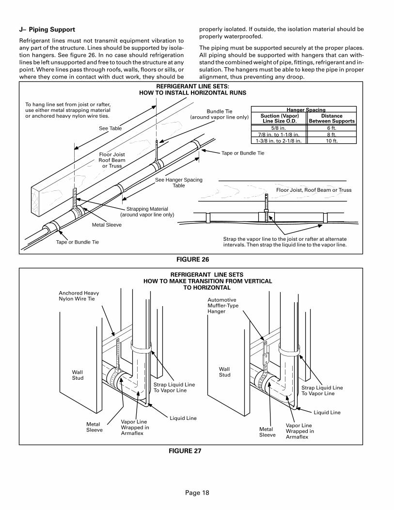
Refrigerant lines must not transmit equipment vibration toany part of the structure. Lines should be supported by isola-tion hangers. See figure 26. In no case should refrigerationlines be left unsupported and free to touch the structure at anypoint. Where lines pass through roofs, walls, floors or sills, orwhere they come in contact with duct work, they should be
properly isolated. If outside, the isolation material should beproperly waterproofed.
The piping must be supported securely at the proper places.All piping should be supported with hangers that can with-stand the combined weight of pipe, fittings, refrigerant and in-sulation. The hangers must be able to keep the pipe in properalignment, thus preventing any droop.
REFRIGERANT LINE SETS:HOW TO INSTALL HORIZONTAL RUNS
FIGURE 26
Metal Sleeve
Tape or Bundle Tie
Bundle Tie(around vapor line only)
Floor JoistRoof Beam
or Truss
Tape or Bundle TieStrap the vapor line to the joist or rafter at alternateintervals. Then strap the liquid line to the vapor line.
To hang line set from joist or rafter,use either metal strapping materialor anchored heavy nylon wire ties.
Floor Joist, Roof Beam or Truss
Strapping Material(around vapor line only)
Hanger Spacing
Suction (Vapor)Line Size O.D.
DistanceBetween Supports
5/8 in.7/8 in. to 1-1/8 in.
1-3/8 in. to 2-1/8 in.
6 ft.8 ft.10 ft.
See Hanger SpacingTable
See Table
REFRIGERANT LINE SETS HOW TO MAKE TRANSITION FROM VERTICAL
TO HORIZONTAL
Liquid Line
Vapor LineWrapped inArmaflex
Strap Liquid LineTo Vapor Line
MetalSleeve
Anchored HeavyNylon Wire Tie Automotive
Muffler-TypeHanger
WallStudWall
Stud
Liquid LineVapor LineWrapped inArmaflex
Strap Liquid LineTo Vapor Line
MetalSleeve
FIGURE 27

Page 19
REFRIGERANT LINE SETS HOW TO INSTALL VERTICAL RUNS (typical new construction shown)
FIGURE 28
PVC Pipe Fiber GlassInsulation
Caulk
Outside Wall
Vapor Line (wrappedwith Armaflex)
Liquid Line
IMPORTANT-Refrigerantlines must
not contact structure.
Outside Wall
Inside Wall
Liquid LineVapor LineIMPORTANT-Refrigerantlines must not contact wall.
Wood BlockBetween Studs
Strap
Sleeve
Wood Block
Strap
Sleeve
Wire Tie
Wire Tie
Wire Tie
NOTE-Similar installation practices should be used if line setis to be installed on exterior of outside wall.

Page 20
VII–Glossary of Terms
accumulator A tank located in the suction line just ahead ofthe compressor. The purpose of the accumulator is to pre-vent liquid from entering the compressor.
ambient The temperature of the air surrounding an object.For a liquid line passing through an attic, the ambient canapproach 180�F. Lennox cooling and heat pump equipmentis designed to provide adequate cooling when the outdoorambient is 115�F.
bypass See Hot Gas Bypass.
bypass valve A valve used in hot gas bypass systems. Thevalve is plumbed so that when the unit is operating at re-duced capacity, liquid refrigerant and hot gas are meteredinto the suction line. See also Hot Gas Bypass.
capillary tube (cap tube) Refrigerant metering device con-sisting of several small diameter tubes feeding liquid refrig-erant into the evaporator. Cap tubes must never be used inlong refrigerant line applications as they provide fair to poorrefrigerant control in extreme conditions.
capacity (capacity loss) A measure of the quantity of refrig-eration available, measured in Btu per hour or watts.
capacity reduction Air conditioning and heat pump systemsdesigned to operate at reduced capacity. Lennox two speedequipment is designed to operate at 60% of full capacityduring low speed operation. Some commercial systems usehot gas bypass as a form of capacity reduction. A form of ca-pacity reduction is used in almost all zoning systems.
column of liquid A length of liquid refrigeration line com-pletely filled with 100% liquid (no bubbles).
condenser A heat transfer device which removes heat fromrefrigerant gas, reduces its temperature, removes latentheat from the refrigerant converting the gas into liquid, thensubcools the liquid.
condensing temperature The temperature in the condensercoil below which latent heat is removed and gas is con-verted into liquid.
distributor A manifold located at the outlet of an expansionvalve designed to feed multiple circuits through the evapo-rator.
double suction riser A type of suction riser used in capacityreduction systems to improve oil entrainment during re-duced capacity operation. A double suction riser consists ofa small riser sized for the capacity of the system when oper-ating at reduced capacity. A second larger riser is plumbedin parallel with the small riser to handle the increased flowwhen the system is operating at full capacity.
drier See Filter Drier.
drop 1) A measure of the downward vertical distance (mea-sured in feet) liquid refrigerant must travel in order to reachthe coil. The weight of the liquid refrigerant increases theliquid line pressure 1/2 pound per foot. 2) See pressure drop.
ell Wrought copper 90� or 45� elbows. Only long radius el-bows should be used as fittings in long refrigerant linesused with Lennox equipment.
entrainment The process of moving oil along the inside sur-face of a refrigerant vapor line. Oil droplets/film attach to theinner surface of the pipe. The refrigerant velocity must besufficient to sweep the oil along (entrain the oil) so it may bereturned to the compressor.
expansion valve See Thermostatic Expansion Valve.
equivalent length (total equivalent length) Wrought copperfittings, filter driers and other devices placed in the refriger-ant line add restriction to the line. The restriction added tothe line is expressed in terms of equivalent feet. The totalequivalent length of a line is equal to the length of the pipeplus the equivalent length of all the fittings, filter driers, etc.placed in the line.
evaporator A heat transfer device (coil) which adds heat toliquid refrigerant, increases its temperature, adds latentheat to the refrigerant converting the liquid into gas, thensuperheats the gas.
filter drier A device placed in the liquid or suction refrigerantlines to filter contaminants from the system and protect theexpansion valve and compressor from potential damage.
flash gas In a liquid refrigerant line, liquid which has lost tem-perature and pressure to the point that gas bubbles begin toform significantly reducing the efficiency of the system.Flash gas can form as a result of friction losses or runningthe liquid line through areas with extremely high ambientsor both.
friction loss See Pressure Drop.
hammer See Liquid Hammer.
hard copper Type L refrigeration grade copper tubing.
hot gas bypass A form of capacity reduction. The system di-verts hot discharge gas and liquid into the suction line by-passing the evaporator coil. The most desirable form of hotgas bypass is the type which feeds hot gas into a side tap onthe distributor on the evaporator coil.
indoor coil The name given to the coil in the indoor unit inheat pump systems.
lift A measure of the upward vertical distance liquid refriger-ant must travel in order to reach the coil measured in feet.The weight of the liquid refrigerant reduces the liquid linepressure 1/2 pound per foot. In air conditioning systems, liftis a factor only if the evaporator is located above the con-denser. In heat pump systems, lift is always a factor due tothe system’s ability to reverse refrigerant flow.
line size The outside diameter (O.D.) of copper pipe used inrefrigeration.
liquid hammer An audible sound heard in liquid refrigerantlines when solenoid valves close. The noise is a result of liq-uid refrigerant travelling at high velocity then stoppingabruptly when the valve closes.
low ambient (temperature) The use of the compressor forcooling when outdoor temperature is below 50�F. Fieldinstalled kits are required to protect the compressor and en-sure proper operation in the event low ambient cooling be-low 50�F is required.
main In systems with multiple refrigerant lines, the name giv-en to the line which feeds or collects refrigerant from multi-ple smaller refrigerant lines.
mass velocity The average velocity of refrigerant in a pipe ex-pressed in feet per minute (fpm).

Page 21
maximum allowable pressure drop The amount of pressuredrop a liquid line can experience before flash gas will beginto form. This number can be calculated if the amount of sub-cooling leaving the condenser is known by subtracting thesubcooling temperature from the summer operating tem-perature then converting the results into a pressure on theR22 saturation chart. The difference in pressure betweensummer operating temperature and the subcooling temper-ature is equal to the maximum allowable pressure drop.
If the outdoor unit is charged to operate with 10�F subcool-ing at 115�F summer operating conditions, the maximumallowable pressure drop will be 35 psi.
metering (metering device) Any device which regulates theflow of liquid refrigerant into an evaporator.
migrate (migration) The tendency of refrigerant gas to slow-ly travel to the coldest part of the piping system during theoff-cycle and condense and collect as liquid.
multiple evaporators Piping arranged so that a single con-denser can operate several evaporators at the same time.
non-recycling pump-down control See Pump Down Con-trol.
oil trap A small U bend located in the suction line where it ex-its the indoor coil. The purpose of the U bend is to trap oiland prevent the oil from filling the suction line.
outdoor coil The name given to the coil in the outdoor unit inheat pump systems.
pressure drop (pressure loss) The loss of refrigerant pres-sure experienced in copper pipe, usually expressed in termsof pounds (psi) per 100 feet.
pump-down control A field installed kit consisting of a sole-noid valve located in the liquid line before the expansionvalve. At the end of a cooling cycle, the controls close thevalve. The compressor continues to run until all refrigerantis returned into the condenser where it is stored as a liquid.The valve remains closed until the next cooling demand.
RFC (refrigerant flow control device) Lennox’ trademarkprotected name for various types of refrigerant metering de-vices with fixed orifice size – RFC: Liquid line serves as the expansion device. It has a pre-cisely sized inside diameter and length which matches thecapacity of the condensing unit and evaporator.RFCII: Fixed orifice for air conditioners located at evaporator.RFCIII: Floating bullet type orifice for heat pump coils whichfront seats for cooling and back seats for heating.RFCIV: Fixed bullet orifice for air conditioners.
riser The name of any length of refrigerant pipe which trans-ports refrigerant vertically upward.
run-around hot gas bypass A type of hot gas bypass systemthat diverts hot discharge gas and liquid directly into thesuction line inside the condensing unit. Although this typeof system requires no piping external to the unit, it is leastdesirable and should not be used.
saturation temperature The temperature at which a gas be-gins to turn into liquid.
sight glass A glass window type device placed in a liquid lineand used for visual inspection of the liquid. It can also beused to determine the point at which all gas bubbles are re-moved from the liquid line. A sight glass is not a good indi-cator of subcooling and cannot be used to determinecharge.
sil-phos Brazing solder composed of silver, phosphorous,and copper and used for welding joints of copper pipe.
slug A column of liquid refrigerant returned to the compres-sor in the suction line. A slug which enters the compressorcan cause permanent compressor damage due to non-com-pressability of liquids.
solenoid valve An electromechanical valve located in the re-frigerant lines and used to shut-off refrigerant flow.
split-coil A single evaporator or condenser coil which isplumbed so that a single coil can serve two or more inde-pendent refrigeration circuits.
subcooling Cooling of refrigerant liquid below its saturatedtemperature while holding it at saturated pressure.
suction riser See Riser.
superheat Heating of refrigeant gas above its saturated tem-perature while holding it at saturated pressure.
thermometer well A device located in the liquid line of mostLennox equipment which allows a thermometer to be in-serted into the liquid line. The well is used for accuratelymeasuring the temperature of the liquid line for chargingpurposes.
thermostatic expansion valve (TXV) An extremely precisetype of expansion device which regulates refrigerant flowinto the evaporator based on the amount of superheat exit-ing the coil. An expansion valve is desirable in long line setapplications because it can maintain control of superheat inextremes of operating conditions.
trap See Oil Trap.
two speed Condensing (or heat pump) outdoor unitsequipped with a two speed compressor. Generally, the com-pressor operates at 60% capacity on low speed and 100% ca-pacity on high speed.
TXV See Thermostatic Expansion Valve.
unload (unloading) See Capacity Reduction.
variable capacity See Capacity Reduction.
velocity A measure of the speed at which refrigerant travelsthrough a pipe.
wrought copper Hammered refrigeration grade copper usedin refrigerant fittings.

Page 22
PLAN6 Lines per Inch

Page 23
CALCULATIONS