design and development of a biped humanoid robot to ... · design and development of a biped...
TRANSCRIPT

SASTECH 67 Volume 11, Issue 1, Apr 2012
Design and Development of a Biped Humanoid Robot to Generate Dynamic Walking Pattern
Shivaraj D.1, Cyril Prasanna Raj P.2, Lasitha M.3
1- M.Sc. [Engg.] Student, 2- Professor and Head, 3- Assistant Professor Department of Electronics and Electrical Engineering,
M. S. Ramaiah School of Advanced Studies, Bangalore- 560 058.
Abstract This study concerns the development, modelling and control of a bipedal humanoid robot and algorithm to generate
dynamic walking pattern using sensory feedback. The implementation of only servo control for robots with walking systems is not sufficient. Even having stable motion pattern and well tuned joint control, a humanoid robot can fall down while walking. Therefore, an adaptively generating gait pattern method is needed, which allows the robot to walk stably in various environments, such as on rough terrain, up and down slopes. To achieve this, the robot has to adapt to the ground conditions with the foot motion and maintain its stability with a torso motion. The gait synthesis is based on the analysis of human’s gait pattern. The proposed algorithm is applied to generate the natural and stable gait pattern of the biped robot.
A small-scale humanoid robot prototype was constructed and used as a test platform for implementing the concepts described; the humanoid robot has totally 18 DoF (Degree of Freedom). Each arm has 3 DoF, each leg has 6 DoF with 2 DoF in ankle allows to control step size and frequency. The main controller communicates with sensor unit and servo motors in real time.
The gait trajectory algorithm is composed of two kinds of trajectory. The first one is Inverse Kinematics (IK). The second one is feedback to the controller from Inertial Measurement Unit (IMU) and the servo motors in the robot, which senses the robot’s velocity, Centre of Gravity (CoG) and posture and it allows to generate and modify motion commands in real time.The motion commands generated comprises of 4 walk states like left leg rise, left leg down, right leg rise and right leg down each with 7 sequences for all the 18 servo actuators to obtain 1 walk cycle with 2 steps, the number of the walk cycles can be specified by the user. The robot was able to walk with a dynamically-stable gait either passively down a ramp, or actively on a flat or slightly uphill surface. From this study we observed that the robot has successfully functioned as driven by the MATLAB code.
1. INTRODUCTION Humanoid robots are expected to assist human activities in daily life. Therefore, humanoid robots are asked to walk natural to provide closeness to human. The human gait is a complex dynamic activity. Although humanoid robots have inherent complexities in locomotion, many successful robots are demonstrated. These robots have abilities to walk, run and dance as humans do. However, despite of these abilities, it is still insufficient to work with human in outdoor environment. Since humanoid robots are commonly composed of very complex hardware and software systems in which various technologies are integrated, it is not only cumbersome but also risky in the aspect of experiment out of doors.
The main objective of this study is to tackle the problem of biped humanoid robot locomotion dynamics and control. In fact, locomotion is the main characteristic studied in humanoid robotics as a humanoid can only resemble like a human if it is able to move like him. And only after achieving the natural walking and locomotion of a humanoid in the human environment, are humanoid robots able to learn how to interact with it and socialize with humans, making use of all of its artificial intelligent. The walking pattern generation in human starts from the sensory organs like eyes, skin, legs etc., based on
information the decisions for the motion planning are made and the pattern generated in the brain.
Fig. 4 Block diagram of walking pattern generation in
(a) human and (b) robot The pattern generated by the brain is updated in real time from the feedbacks provided by the sensory organs due to the possible changes in the terrain and environment. The reflexory control of the body also helps make the decisions for the walking but only comes into action when the body experiences any of the following

SASTECH 68 Volume 11, Issue 1, Apr 2012
conditions like fright, flight and fight collectively called 3Fs.
The sensory feedback and reflexes together give the fine motion control of the muscles involved in walking as shown in the Figure 1 (a) illustrating the steps involved the process of walking pattern generation in human (Shuuji Ka jita, Fu mio Kanehiro, Kenji Kaneko, Kiyoshi Fu jiwara, Kazuhito Yokoi and Hirohisa Hirukawa, 2002).In case of the robot the sensory feedbacks may be obtained from various sources like the actuators, Inertial Measurement unit (IMU), Force Sensing Resistor (FSR) in foot etc. the information from the sensors are processed in the main controller and walking pattern synthesized for the robot to walk in the flat surface is based on the method of called Inverse Kinematics (IK) are updated for the varying terrain condition as shown in the Figure 1 (b) illustrating the steps involved the process of walking pattern generation in robot.
2. PROBLEM STATEMENT
To design and develop a biped humanoid robot with 18 Degrees of Freedom (DoF) to generate dynamic walking pattern using the feedbacks from the servo motors and Inertial Measurement Unit (IMU).
3. METHODOLOGY • Literature review has been conducted on human
anatomy, anthropometry (proportion data), Anthropomorphic (motion in different planes)
• The human proportion data has been scaled and a biped humanoid robot model is designed in SolidWorks
• A humanoid robot prototype has been constructed and is used as a test platform for implementing the proposed concepts
• The humanoid robot has totally 18 DoF (Degree of Freedom). Each arm has 3 DoF, each leg has 6 DoF with 2 DoF in ankle to control step size and frequency
• The PCB for sub controller and IMU has been designed in Altium Designer and has been manufactured using “Toner transfer method”
• The robot is controlled using MATLAB (main controller)
• The MATLAB generates the action gait using Inverse Kinematics (IK) algorithm and feeds to robot’s servo motors via sub controller
• The IMU in the robot detects any change in the orientation of robot due to the walking surface and sends the feedback to the main controller in real time
• Based upon the data like robot’s velocity, Centre of Gravity (CoG) and posture the main controller will dynamically generate and modify walking pattern in real time
• Hence the Robot walks with a dynamically-stable gait on a flat, slightly uphill surface and down a ramp
4. DESIGN AND IMPLEMENTATION The main goal of the study is to design a biped robot that is able to perform dynamic walk, resembling humans as
much as possible, in doing so the efficiency of bipedal locomotion can be very high. The motion command is generated in Matlab, it compiles and offloads control algorithm to the humanoid robot with the sensory data and servo actuation commands being able to stream back and forth with the humanoid servos.
4.1 Mechanical Design and Implementation In order to achieve human-like stable gait with low power consumption the following key points have been determined and should be emphasized in the design
• Resemble the proportions of a human, that is, the length of the limbs should follow the ratios found in humans
• Joints on humans with more than one degree of freedom (DoF) in the same plane should be designed as such on the robot
• The robot has to be designed to house the electronics somewhere in the body technique.
Figure 2 shows the outcome of study conducted in the human anatomy including the (a) structure of bones and human proportions and (b) various DoF in the body aiding to the bipedal walking.
Fig. 5 (a) Human dimensions, (b) kinematics diagram
representing the DoF in human proportions
Dimension Stature H1 1740 R1 430Shoulder height H2 1425 R2 352Elbow height H3 1090 R3 270Hip height H4 920 R4 250Knee height H5 545 R5 136Foot length H6 265 R6 97Foot breadth H7 95 R7 61Thigh thickness H8 160 R8 46Shoulder to elbow H9 365 R9 84Elbow to finger tip H10 475 R10 115
Value for human
Value for robot
Table 1. Robot proportion data based on the human The human proportion data of various parts of the body are listed in Table 1 and the corresponding proportion
SASTECH 69 Volume 11, Issue 1, Apr 2012
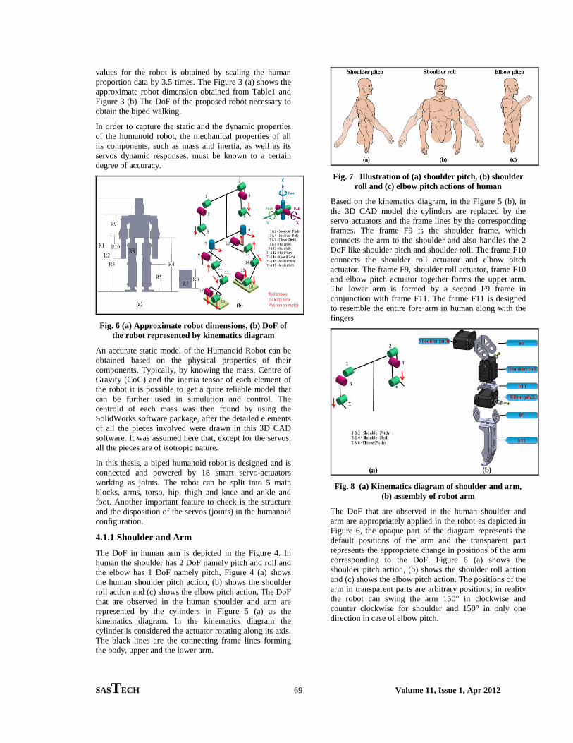
values for the robot is obtained by scaling the human proportion data by 3.5 times. The Figure 3 (a) shows the approximate robot dimension obtained from Table1 and Figure 3 (b) The DoF of the proposed robot necessary to obtain the biped walking.
In order to capture the static and the dynamic properties of the humanoid robot, the mechanical properties of all its components, such as mass and inertia, as well as its servos dynamic responses, must be known to a certain degree of accuracy.
Fig. 6 (a) Approximate robot dimensions, (b) DoF of
the robot represented by kinematics diagram An accurate static model of the Humanoid Robot can be obtained based on the physical properties of their components. Typically, by knowing the mass, Centre of Gravity (CoG) and the inertia tensor of each element of the robot it is possible to get a quite reliable model that can be further used in simulation and control. The centroid of each mass was then found by using the SolidWorks software package, after the detailed elements of all the pieces involved were drawn in this 3D CAD software. It was assumed here that, except for the servos, all the pieces are of isotropic nature.
In this thesis, a biped humanoid robot is designed and is connected and powered by 18 smart servo-actuators working as joints. The robot can be split into 5 main blocks, arms, torso, hip, thigh and knee and ankle and foot. Another important feature to check is the structure and the disposition of the servos (joints) in the humanoid configuration.
4.1.1 Shoulder and Arm The DoF in human arm is depicted in the Figure 4. In human the shoulder has 2 DoF namely pitch and roll and the elbow has 1 DoF namely pitch, Figure 4 (a) shows the human shoulder pitch action, (b) shows the shoulder roll action and (c) shows the elbow pitch action. The DoF that are observed in the human shoulder and arm are represented by the cylinders in Figure 5 (a) as the kinematics diagram. In the kinematics diagram the cylinder is considered the actuator rotating along its axis. The black lines are the connecting frame lines forming the body, upper and the lower arm.
Fig. 7 Illustration of (a) shoulder pitch, (b) shoulder
roll and (c) elbow pitch actions of human
Based on the kinematics diagram, in the Figure 5 (b), in the 3D CAD model the cylinders are replaced by the servo actuators and the frame lines by the corresponding frames. The frame F9 is the shoulder frame, which connects the arm to the shoulder and also handles the 2 DoF like shoulder pitch and shoulder roll. The frame F10 connects the shoulder roll actuator and elbow pitch actuator. The frame F9, shoulder roll actuator, frame F10 and elbow pitch actuator together forms the upper arm. The lower arm is formed by a second F9 frame in conjunction with frame F11. The frame F11 is designed to resemble the entire fore arm in human along with the fingers.
Fig. 8 (a) Kinematics diagram of shoulder and arm,
(b) assembly of robot arm
The DoF that are observed in the human shoulder and arm are appropriately applied in the robot as depicted in Figure 6, the opaque part of the diagram represents the default positions of the arm and the transparent part represents the appropriate change in positions of the arm corresponding to the DoF. Figure 6 (a) shows the shoulder pitch action, (b) shows the shoulder roll action and (c) shows the elbow pitch action. The positions of the arm in transparent parts are arbitrary positions; in reality the robot can swing the arm 150° in clockwise and counter clockwise for shoulder and 150° in only one direction in case of elbow pitch.

SASTECH 70 Volume 11, Issue 1, Apr 2012
Fig. 9 Illustration of (a) shoulder pitch, (b) shoulder
roll and (c) elbow pitch actions of the robot
4.1.2 Torso The torso is the base in human; it connects all limbs and houses the organs. Therefore in robot the design of the torso is done with an intension to be the base of the robot and connect all limbs and also should hold the on-board servo controller and IMU board. The Figure 7 shows the illustration of human torso and the location of Centre of Gravity (CoG).
Fig. 10 Human torso and location of CoG
Fig. 11 (a) Kinematics diagram of hip yaw, (b)
assembly of robot torso Since torso is the base of the does not have any direct DoF but connects to the limbs through actuators. Figure 8 (a) shows the kinematics diagram of the actuators like shoulder pitch and hip yaw present in torso. The exploded view of the torso as depicted in Figure 8 (b) shows the corresponding actuators placed in their positions, the frame F12 act as shoulder and hence it is also called the shoulder frame, the frame F13 act as chest compartment and houses the servo controller, the frame F14 forms the waist or groin compartment, in human this
is position of CoG and hence it is the perfect place to house the IMU.
4.1.3 Hip In human the waist has 2 DoF namely pitch and yaw and the hip has 3 DoF namely yaw, pitch and roll. But in the proposed robot model the waist is not included because it does not contribute to biped walking.
The hip is a separate unit, since the torso of the robot is the base the hip yaw actuators are attached to torso using the frame F16 as shown in Figure 8 (b). The Figure 9 illustrates the 3 DoF like roll and pitch and yaw in human hip.
Fig. 12 Illustration of (a) hip roll, (b) hip pitch and (c)
hip yaw actions of human
Fig. 13 (a) Kinematics diagram of hip roll and hip
pitch, (b) assembly of robot hip Figure 10 (a) shows the kinematics diagram of the actuators like hip roll and hip pitch. Frame F8 as depicted is Figure 10 (b) connects the hip roll and pitch actuators to the hip yaw actuator attached to the torso.
Fig. 14 Illustration of (a) hip roll, (b) hip pitch and (c)
hip yaw actions of the robot
SASTECH 71 Volume 11, Issue 1, Apr 2012
The frame F4 connects hip roll and pitch actuators to each other and always ensures the axis of these two actuators are perpendicular to each other and to the hip yaw actuator. The frame F3 is the manufacturer supplied and it aides in hip roll action. Figure 11 Illustrates (a) hip roll, (b) hip pitch and (c) hip yaw actions of the robot.
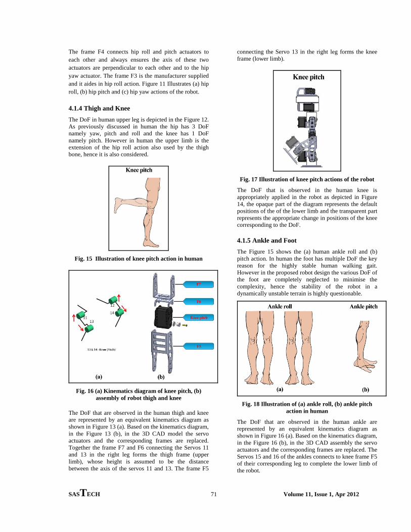
4.1.4 Thigh and Knee The DoF in human upper leg is depicted in the Figure 12. As previously discussed in human the hip has 3 DoF namely yaw, pitch and roll and the knee has 1 DoF namely pitch. However in human the upper limb is the extension of the hip roll action also used by the thigh bone, hence it is also considered.
Fig. 15 Illustration of knee pitch action in human
Fig. 16 (a) Kinematics diagram of knee pitch, (b)
assembly of robot thigh and knee
The DoF that are observed in the human thigh and knee are represented by an equivalent kinematics diagram as shown in Figure 13 (a). Based on the kinematics diagram, in the Figure 13 (b), in the 3D CAD model the servo actuators and the corresponding frames are replaced. Together the frame F7 and F6 connecting the Servos 11 and 13 in the right leg forms the thigh frame (upper limb), whose height is assumed to be the distance between the axis of the servos 11 and 13. The frame F5
connecting the Servo 13 in the right leg forms the knee frame (lower limb).
Fig. 17 Illustration of knee pitch actions of the robot
The DoF that is observed in the human knee is appropriately applied in the robot as depicted in Figure 14, the opaque part of the diagram represents the default positions of the of the lower limb and the transparent part represents the appropriate change in positions of the knee corresponding to the DoF.
4.1.5 Ankle and Foot The Figure 15 shows the (a) human ankle roll and (b) pitch action. In human the foot has multiple DoF the key reason for the highly stable human walking gait. However in the proposed robot design the various DoF of the foot are completely neglected to minimise the complexity, hence the stability of the robot in a dynamically unstable terrain is highly questionable.
Fig. 18 Illustration of (a) ankle roll, (b) ankle pitch
action in human
The DoF that are observed in the human ankle are represented by an equivalent kinematics diagram as shown in Figure 16 (a). Based on the kinematics diagram, in the Figure 16 (b), in the 3D CAD assembly the servo actuators and the corresponding frames are replaced. The Servos 15 and 16 of the ankles connects to knee frame F5 of their corresponding leg to complete the lower limb of the robot.

SASTECH 72 Volume 11, Issue 1, Apr 2012
Fig. 19 (a) Kinematics diagram of ankle roll and
pitch, (b) assembly of robot ankle and foot The foot of the robot is made by the combination two frames F2 and F1.
Fig. 20 Illustration of (a) ankle roll, (b) ankle pitch
actions of the robot
The DoF that is observed in the human ankle is appropriately applied in the robot as depicted in Figure 17, (a) ankle roll action and (b) ankle pitch action.
After performing mechanical analysis within the SolidWorks the parts are virtually assembled to form the complete robot. The Figure 17 illustrates the dimensions of the various parts of robot’s body whose values are listed in Table 2, Figure 18 (a) highlights the identification number of all the servos present in the robot.
Fig. 21 (a) Identification number of the servo motors
in the root, (b) Actual robot dimensions
Dimension
Shoulder height r2 357Elbow height r3 269Hip height r4 249Knee height r5 128Foot length r6 97Foot breadth r7 61Thigh thickness r8 46Shoulder to elbow r9 88Elbow to finger tip r10 115Torso breadth r11 104Torso length r12 108Torso height r13 105
Value for robot (mm)
Table 2. Dimensions values for robot
Fig. 22 Constructed biped humanoid robot with 18
DoF
4.2 Electronics Implementation
4.2.1 Servo Actuator The servo actuators are the ’muscles’ of the humanoid. The servo shown in Figure 20 has some special features such as
• Precision DC motor and a control circuitry with networking functionality.
• 1 MBPS communication speed. • Full feedback on Position (300°), Speed, DC
current, Voltage and Temperature. • Voltage, DC current and Temperature automatic
shutdown. • No load speed of 59 rpm (at 12V, 1.5A) • High Torque servo with 1.47 Nm (at 12V, 1.5A)
The servos communicate through asynchronous serial communication with 8 bit, 1 stop bit and no parity.

SASTECH 73 Volume 11, Issue 1, Apr 2012
Fig. 23 The servo-actuator and its dimensions
(Robotis 2010)
4.2.2 Servo Controller The sub controller is necessary to interface the servo actuators with the PC and enable to transmit and receive data from the Matlab environment. There are 18 servo actuators in the robot and have a communication speed of 1MBPS at the baud rate of 1000000 bps. Hence a fast communication protocol is needed and USB protocol is chosen to be the solution for the demand.
Fig. 24 Schematic diagram of the servo controller
Pin No. Name Type Description
15 USBDP I/O USB Data Signal Plus16 USBDM I/O USB Data Signal Minus 1 TXD Output Transmit Asynchronous Data
Output5 RXD Input Receiving Asynchronous Data
22 CBUS1 I/O Default internal EEPROMconfiguration is RXLED
23 CBUS0 I/O Default internal EEPROMconfiguration is TXLED
13 CBUS2 I/O Default internal EEPROMconfiguration is TXDEN
Table 2. Pins of FT232RL used by the servo controller to establish the communication protocol
The schematic diagram for the servo controller is shown in Figure 21. The servo controller along with the USB to serial chip and multiplexer unit also has USB type B
receptacle and 6 Molex 3 pin connecter to connect the servo actuators, 2 LEDs at CBUS0 and CBUS1 of the FT232RL chip to indicate the data transfers and power supply side of the PCB has a DC power jack, 5 amps Fuse and a SPST slide switch.
Fig. 25 Servo controller PCB
Figure 22 shows the PCB implementation of servo controller and Table 4 lists the bill material of servo controller.
ID Component Description Power Rating
U1 FT232RL USB to serial converter 5V, 100mA U2 74HC126 Quad tri-state buffer 5V, 1μA U3 74HC04 Hex inverter 5V, 1μA D1 LED Red, TX LEDD2 LED Green, RX LED
R1-R2 270Ω ResistorR3 100Ω ResistorR4 10kΩ ResistorC1 0.1μF Capacitor
P1-P6 99-99-0987 3-pin Molex connector 12.0V, 1.5A S1 SPDT Slide switch 250V, 5A F1 Fuse Radial Lead 250V, 5A J1 USB Receptacle Type-B 5V, 500mA J2 DC Power Power jack 16V, 2.5A
Table 3. Bill of material for servo controller 4.2.3 Inertial Measurement Unit (IMU)
Fig. 26 6 DoF digital IMU
IMU is an electronic device that measures the robot’s velocity, orientation, and gravitational forces, using a

SASTECH 74 Volume 11, Issue 1, Apr 2012
combination of accelerometer and gyroscope. The accelerometer detects the current rate of acceleration in three-dimensional space and the gyroscope detects changes in rotational attributes like roll, pitch and yaw. Figure 23 shows the IMU’s physical circuit. Accelerometer Accelerometers are used to sense both static (e.g. gravity) and dynamic (e.g. sudden starts/stops) acceleration. It can measure either in units of meters per second squared (m/s2), or G-force (g), which is about 9.8m/s2. One of the more widely used applications for accelerometers is tilt-sensing. Because they are affected by the acceleration of gravity, an accelerometer can tell how it's oriented with respect to the Earth's surface. An accelerometer can also be used to sense if a device is in a state of free fall.
Gyroscope Gyroscopes are used to measure angular velocity, i.e. how fast an object is spinning about an axis. When trying to monitor the orientation of an object in motion, an accelerometer may not give enough information to know exactly how it's oriented. Unlike accelerometers gyros are not affected by gravity, so they make a great complement to each other. It can measure either in units of rotations per minute (rpm), or degrees per second (°/s). The three axes of rotation are either referenced as x, y, and z, or roll, pitch, and yaw.
Microcontroller and Multiplexer IMU designed for this study incorporates 2 sensors - an ADXL345 (triple-axis accelerometer), and ITG-3200 (triple-axis gyroscope) together gives 6 degrees of inertial measurement. The outputs of the sensors should be processed; therefore an efficient microcontroller is to be selected. Initially many microcontrollers were considered and finally ATmega328 was selected.
Fig. 27 Schematic diagram of IMU data processing
unit
Figure 24 shows the schematic diagram of IMU data processing unit. The data line SDA and the clock line SCL of the accelerometer and gyros are electrically tied and given to the corresponding I2C pin of the microcontroller. The serial output of the microcontroller should be multiplexed into a single data line in order to
be connected along with the servo-actuator in daisy chain link. The multiplexer used in the IMU board has a single tri-state buffer chip called 74HC126, the TX of the serial data line is given to first buffer and is excited by the pin PD7 and the RX of the serial data line is given to second buffer and it is excited by the pin PD6 of the microcontroller. Since the IMU board is connected in series with the servo-actuators using the 3-pin Molex connector, the servo-actuators’ 12V power line can provide the power to the IMU board with the usage of proper voltage regulators like LM1117 5V and LM1117 3.3V for microcontroller and IMU respectively.
Figure 25 shows the PCB implementation of Inertial Measurement Unit (IMU) and Table 5 lists the bill material of IMU.
Fig. 28 Inertial measurement unit PCB
The walking trajectory generation involves various factors to be considered. These factors contribute to the generation of the gait in sequence of the walk cycle.
Fig. 29 Illustration of offset of the foot along X, Y, Z
axes
Figure. 26 illustrates the offset of the foot (a) along X axis in front and back direction, (b) along Y axis in right and left direction and (c) along Z axis in up and down direction, the offsets are measured in mm

SASTECH 75 Volume 11, Issue 1, Apr 2012
ID Component Description Power Rating
8-Bit , 32k flash memory
Micro controllerU2 LM1117-5.0 5V Voltage regulator 5V, 800mAU3 LM1117-3.3 3.3V Voltage regulator 3.3V, 800mAU5 74HC126 Quad tri-state buffer 5V, 1μAU6 ADXL345 3-axis Accelerometer 3.3V, 150μA U7 ITG3200 3-axis Gyroscope 3.3V, 6.5mA Y1 16MHz Crystal oscillator 5V, 1μA
R1-R2 10kΩ ResistorR3 100Ω Resistor
C1-C4 10μF CapacitorC5-C7 0.1μF Capacitor
C8 100pF CapacitorC9-C10 22pF Capacitor
P1 ISP connector Programmer connector 5V, 1μAP4 99-99-0987 3-pin Molex connector 12.0V, 1.5A
U1 ATmega328 5V, 0.3mA
Table 4. Bill of material for IMU4.3 Walking Gait
Generation
Fig. 30 Illustration of offset of the foot across X, Y, Z
axes Fig. 27 illustrates the offset of the foot (a) across X axis as roll offset, (b) across Y axis as pitch offset and (c) across Y axis as yaw offset, the offsets are foot measured in degree.
Fig. 31 Illustration of hip pitch offset
Figure 28 illustrates the offset of the hip across Y axis (pitch) measured in degree, this offset is used to compensate pull back action of the robot due the mass of the body.
Fig. 32 Illustration of period time
Figure 29 illustrates the period time, the time required for the robot to complete two full steps, the time is measured in seconds.
Fig. 33 Illustration of DSP ratio
Figure 30 illustrates the Double Stance Period (DSP) ratio, time ratio of both feet on ground to one foot on ground, the time is measured in seconds.
Fig. 34 Illustration of (a) forward step distance, (b)
side step distance Figure 31 illustrates the differential distance between right and left foot during (a) forward and (b) side walking, the distances are measured in mm.

SASTECH 76 Volume 11, Issue 1, Apr 2012
Fig. 35 Illustration of foot height
Figure 32 illustrates the elevation of the foot during walk; the foot height is measured in mm.
Fig. 36 Illustration of right/left swing
Figure 33 illustrates the robot’s swing to right and left during walk to maintain CoG, the swing is measured in mm.
Fig. 37 Illustration of top/down swing
Figure 34 illustrates the robot’s swing to up and down during walk; the swing is measured in mm.
Fig. 38 Illustration of pelvis offset
Figure 35 illustrates the robot’s roll offset at pelvis level
Fig. 39 Illustration of step direction
Figure 36 illustrates the robot’s stepping direction towards right or left.
The dynamic walking pattern generation and adaptation to different and unpredictable environment is explained in the figure 37, showing the possible outcomes of a kinematics representation of the robot in different terrain conditions with and without IMU. In figure 37 (a) and (b) illustrates the robot walking in flat surface from different view (c) robot walking in uphill without IMU, in this condition the CoG of the robot will fall outside the body and the robot will topple (d) and (e) robot walking in uphill and downhill with IMU, in this condition the CoG is always maintained within the body by providing corresponding equivalent offset, in this case the hip offset of θ° to robot if the surface is inclined at θ° and hence the robot will be stable.

SASTECH 77 Volume 11, Issue 1, Apr 2012
Fig. 40 Dynamic walking gait generation and
adaptation using IMU
5. RESULTS AND DISCUSSION This section illustrates the results from the implementation of the walking gait generated using Inverse Kinematics (IK) to the robot to obtain stable walking pattern.
5.1 Testing of Generated Gait in the Biped Humanoid Robot The values for the factors involved in the generation of walking gait are computed using Inverse Kinematics method. The values are tabulated in the Table 6.
Factors involved in walking gait generation
Values
X offset (mm) -10Y offset (mm) 5Z offset (mm) 20
Roll (x) offset (degree) 0.0°Pitch (Y) offset (degree) 0.0°Yaw (Z) offset (degree) 0.0°Hip pitch offset (degree) 9°
Pelvis offset (degree) 3.0°
Period time (sec) 2.24
Step forward/back (X-direction)(mm)
50
Foot Height (mm) 40Swing right/left (mm) 20Swing top/down (mm) 5
Table 5 Values of various factors involved in walking gait generation
Servo ID 1 2 3 4 5 6 71 423 427 433 442 453 466 4802 473 477 483 492 503 516 5309 500 499 502 505 507 507 505
10 492 485 478 472 468 468 47211 374 379 384 387 390 392 39212 583 594 616 644 677 695 69113 681 679 676 672 670 670 67214 375 355 321 284 248 248 28415 590 593 594 594 594 596 59916 400 391 379 371 367 385 41817 498 492 488 485 484 484 48518 493 487 482 478 475 475 478
Table 6 Servo positions for left leg rise during walk state
Based upon the values obtained for the different factor involved in walking gait generation, a 28 sequence of values for each of the 18 servos are computed to generate one complete walking cycle with 2 steps. The values obtained for the one complete walking cycle can be looped to obtain many numbers of steps.
Servo ID 8 9 10 11 12 13 141 494 508 521 532 541 547 5512 544 558 571 582 591 597 6019 502 499 500 504 511 518 525
10 478 485 492 499 506 513 52011 392 393 396 402 410 422 43512 683 671 662 660 662 659 65513 676 679 681 681 677 668 65414 321 355 375 370 356 347 34315 602 607 612 617 621 624 62216 446 468 479 473 460 448 44017 488 492 498 504 511 518 52518 482 487 493 499 506 513 520
Table 7. Servo positions for left leg down during walk state

SASTECH 78 Volume 11, Issue 1, Apr 2012
Servo ID 15 16 17 18 19 20 211 551 547 541 532 521 508 4942 601 597 591 582 571 558 5449 532 539 546 552 556 556 552
10 524 525 522 519 517 517 51911 441 430 408 380 347 329 33312 650 645 640 637 634 632 63213 649 669 703 740 776 776 74014 343 345 348 352 354 354 35215 624 633 645 653 657 639 60616 434 431 430 430 430 428 42517 531 537 542 546 549 549 54618 526 532 536 539 540 540 539
Table 8. Servo positions for right leg rise during walk state
Servo ID 22 23 24 25 26 27 281 480 466 453 442 433 427 4232 530 516 503 492 483 477 4739 546 539 532 525 518 511 504
10 522 525 524 520 513 506 49911 341 353 362 364 362 365 36912 632 631 628 622 614 602 58913 703 669 649 654 668 677 68114 348 345 343 343 347 356 37015 578 556 545 551 564 576 58416 422 417 412 407 403 400 40217 542 537 531 525 518 511 50418 536 532 526 520 513 506 499
6. CONCLUSIONS In this study a biped humanoid robot with 18 DoF to be able to walk with human gait has been developed. MATLAB has been used to construct an USB protocol for communication in real time between the PC and the humanoid robot. The construction of IMU to measure the velocity and orientation of the humanoid robot in real time and sent the data to the PC and uses the information to balance the robot. From this study we observed that the robot has successfully functioned as driven by the MATLAB code.
REFERENCES [1] Shuuji Ka jita, Fu mio Kanehiro, Kenji Kaneko,
Kiyoshi Fu jiwara, Kazuhito Yokoi and Hirohisa Hirukawa, 2002
[2] A Realtime Pattern Generator for Biped Walking, Proceedings of the 2002 IEEE International Conference on Robotics & Automation,Washington, DC.
[3] Robotis (2010) Servo communication protocol [online] from <http//support.robotis.com/en/product/dynamixel/communication/dxl_packet.htm> [09 September 2011]
Table 9. Servo positions for right leg down during
walk state