design and deployment of reliable physical … and deployment of reliable physical infrastructure...
TRANSCRIPT

Design and Deployment of Reliable Physical Infrastructure Networks for the Industrial Plant Floor
David Dohm, RCDDPanduit Corporation
Robert ElliottPanduit Corporation

• Plant Floor Networks- History and Evolution• Use Case for Deployment of Standard TCP/IP Ethernet on the Plant Floor• Contrasts between Enterprise and Plant Floor Ethernet Network Environments• Codes and Standards which govern Plant Floor Ethernet Networks• MICE Definition, Standards, and Implementation on the Plant Floor• Optimizing the Logical and Physical Network Layers• Effective Bonding and Grounding to Mitigate Noise Disturbance of Networks
Agenda – History and Overview

• Cabling Overview – Locations within the Plant Floor• Cabling Standards and Test Methods• Copper Cabling on the Plant Floor• Fiber Cabling on the Plant Floor• Fiber Optic Cable Types, Constructions, Transceivers, and Loss Budgeting• Network Cable Pathways and Routing• Structured versus Point-To-Point Cabling
Agenda – Cabling On the Plant Floor

Plant Floor Network Evolution• Earliest Networks Transported Alarm and Status Information
• Bandwidth Requirements were limited– Low Update Rate Requirements allowed for simple Parity Check and Error Correction– Network node counts were limited in size
• Physical Media and Signaling Levels were Designed for Hostile Environments– Amplitudes were often +/- 15 volts– Character Rates were typically 1200 – 38K Baud– Media was Often Shielded Pair or Coaxial
• Control and Information Processing Networks were not connected• Protocols and Media were incompatible• Needs for Archival and Analysis of data was minimal

Legacy Plant Floor Environments• Most Power Consuming Devices were Switched “On or Off”
• Inductive Loads were switched at a low rate of repetition– Radiated or Conducted Transient Energy was intermittent
• Control and Power Cabling were routed separately• Pathways were typically Rigid Metal Conduit• Logic Controllers and Power Switching devices were isolated
– Interface was usually via discrete outputs and conductors– Enclosures were separate

Evolution of Plant Floor TopologyModern Networked MCC Traditional PLC panel and Motor Control
Center
Control Network terminated in PLC cabinet with power control devices in separate enclosures
Ethernet Cabling and Network Devices in same enclosure with power control devices

Extension of Ethernet to the Plant Flooro Business Needs Required Information Transport between Enterprise
and Plant Floor Networks• Economic
– Plant Consolidation Made Agile Manufacturing, Asset Utilization, and Downtime More Critical» Return on Investment» Product Availability
– Reduction in Lot Sizes for Product Recall » Lower cost of Scrap and Transportation» Lessen Damage to Reputation due to Media Attention
• Regulatory Compliance– Expansion of Attributes Monitored and Recorded for Recall and Analysis– Tracking of Raw Materials through Production Lots

Benefits of Ethernet on the Plant Floor– Consolidation of Proprietary Control Network Infrastructure
• Allowed for Standardization in Media Types– Reduced Spare Materials and Personnel Training for Maintenance– Simplified Planning for Moves or Expansion of Equipment– Eliminates the need for Hardware Gateway Appliances between network segments
» Reduced the complexity of Controller Interfaces» Eased Programming and Troubleshooting of Programmable Controllers
• Enables Use of Unified Network Health Monitoring and Troubleshooting– Provides opportunity for Predictive Monitoring of Networks– Similar diagnostic and troubleshooting tools can be used Plant Floor and Enterprise Wide

Common Attributes of Ethernet in the Enterprise
• Ethernet has often been initially deployed by, and for, the Business Management sector of an enterprise for use in “office spaces”• Physical Media was designed for a relatively benign space
• Temperature was within range of comfort for workers• Shock and Energy hazards are contained within inaccessible spaces in equipment and building structures• There were few mechanical hazards present• Caustic or Corrosive Chemicals and Solvents were present in small amounts in contained spaces
• Networks were installed and maintained by personnel specifically trained for the task• Configuration, Diagnosis, and Troubleshooting was generally done in a “command line” interface• The scope of responsibilities rarely extended beyond Network or Information Processing tasks
• Security and Reliability of Information Transport were primary goals• Delays of Seconds or Minutes in Printing or Message delivery were tolerable• Access to internal and external resources were equally necessary
• Deployment and Management of Assets was generally centralized• Dynamic Address Assignment and Name Resolution simplified installation and movement of devices• Standard protocols (such as SNMP) were available for monitoring in most networked devices

Physical Challenges for Ethernet on the Plant Floor
• Plant Floor Ethernet occupies a space managed by the Operations and Maintenance Staff of the Company
• Physical Media is now routed through, and connectivity located in, more rigorous space• Temperature may be far beyond the range of comfort for workers in “street attire”• Shock and Energy hazards may be present in the same spaces as network devices• Cabling may be subject to continuous motion, vibration, and impact by moveable machinery• Caustic or Corrosive Chemicals and Solvents may be continuously or repeatedly present in significant amounts
• Determinism may be equally important as Security and Reliability of Information Transport • Delays of milliseconds in packet delivery may slow or halt a production process• Access to external resources may be of far less importance than local devices

Management Challenges for Ethernet on the Plant Floor
• Networks may be installed and maintained by personnel responsible for a wide range of tasks• Troubleshooting will likely be done by personnel unfamiliar with common network diagnostic tools and their interfaces• Few alternatives may exist to rapid repair of specific network segments and devices
• Processes likely cannot be “relocated to other workspaces” as can individual employees• Loss of a single machine may bring down an entire production line• Machines cannot easily be “virtualized” or configured to be individually redundant
• Deployment and Management of Assets may be localized and more complex• Fixed IP Addressing required by programmable controllers may complicate replacement or movement of devices• Standard management protocols (such as SNMP) are rarely available in network devices other than managed switches

Ownership of the Network on the Plant Floor• Network diagrams (physical or logical) often show separation of
Enterprise and Manufacturing networks by a “DMZ”• This segmentation may not exist in all cases
• Information Technology personnel may be tasked with maintenance of all managed switches in the facility
• Maintenance or Operations staff may not have skill sets to manage networks
• Security policies may require centralized management of access control
• This may dictate the type of switch used (managed or unmanaged) and their physical location
• Safety or Collective Bargaining Unit work rules or Good Manufacturing Practices may govern physical access to equipment in some spaces
• Configuration and maintenance of all network switches and routers may be outsourced

Life Safety Codes• Many of the same Life Safety Codes govern the design and installation of power distribution and information or control networks in
both enterprise and manufacturing plant floor spaces
• NFPA 70- National Electrical Code, United States• CSA C22.1- Canadian Electric Code, Canada• NOM-001-SEDE 2012- Instalaciones eléctricas (utilización), Mexico• IEC 60364- Low-voltage electrical installations, International Electrotechnical Commission
• Many countries have adopted portions of the IEC Standard or used it as a template for local standards• BS7671 IEE Wiring Regulations, United Kingdom• VDE 0100, Germany
• Other Life Safety Codes may affect both Enterprise and Manufacturing or Energy Production Facilities, such as IEEE C2-2012 National Electrical Safety Code, where communications and power distribution networks traverse between buildings and equipment in underground or aerial installations where installed or maintained by owners (rather than utilities). Similar codes may exist in specific locales or countries outside the United States.
• Designers and professionals developing specifications for global customers must consider the areas of Harmonization and differences between these Life Safety Codes in the course of preparing deliverables for, or making specific recommendations to, their clients.

Generic and Industrial Standards Throughout the World
Region of the World
North and South America
Europe (Cenelec)
Europe, Other Areas of World
Generic Premise Cabling Standard
ANSI / TIA-568 Series EN 50173-1 IEC / ISO 11801
Series
Industrial Premises Cabling Standard ANSI / TIA-1005-A EN 50173-3 IEC / ISO 24702
Numerous other standards apply to specific regions, such as the AS/NZS (Australian and New Zealand) and Japanese standards, some of which overlap (or are more specific to) portions of those mentioned above.

Industrial Network Infrastructure Standards
• Other Standards apply specifically to Industrial Plant Floors and similar facilities
• TIA 1005 Telecommunications Infrastructure Standard for Industrial Premises• ISO/IEC 24702 Telecommunications installations - Generic cabling - Industrial premises
• These are the Standards which we will examine more closely throughout this session, along with some requirements of NFPA 70 that are specific to the manufacturing space.
• Because of the significant effect that Bonding and Grounding may have on noise mitigation on the Manufacturing Floor and in similar environments, we will also address specific elements of TIA-607 - Telecommunications Grounding (Earthing) and Bonding for Customer Premises. Although this standard applies to all occupancies, the unique issues created by modern power control devices on the plant floor and their propensity for generation of spurious energy in significant magnitudes in frequency spectra well above that of the 60 Hz power distribution system, make effective design and implementation of the bonding system critical.
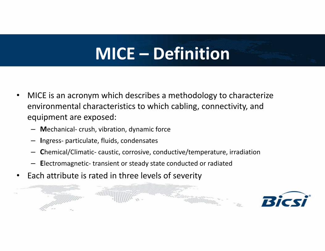
MICE – Definition
• MICE is an acronym which describes a methodology to characterize environmental characteristics to which cabling, connectivity, and equipment are exposed:– Mechanical- crush, vibration, dynamic force– Ingress- particulate, fluids, condensates– Chemical/Climatic- caustic, corrosive, conductive/temperature, irradiation– Electromagnetic- transient or steady state conducted or radiated
• Each attribute is rated in three levels of severity

MICE – Standards• Mice ratings for Facility Areas in which Network Infrastructure Components
may be present are defined and quantified in infrastructure standards such as:– IEC 24702– TIA-1005– TIA-568-C.0 Annex F (Environmental Classifications) Table 8
• Contains measurable limits to each Attribute (with some subclassifications) where these limits have been characterized
• Some are not yet defined, and labeled “ffs” (for further study)
– MICE is mentioned in the TDMM, but not covered to the depth of the standards referenced above.

MICE – MechanicalMechanical M1 M2 M3
Shock/bump (see a)
Peak acceleration 40 m/s-2 100 m/s-2 250 m/s-2
Vibration
Displacement amplitude(2 Hz to 9 Hz) 1.5 mm 7.0 mm 15.0 mm
Acceleration amplitude(9 Hz to 500 Hz)
5 m/s-2 20 m/s-2 50 m/s-2
Tensile force See b) See b) See b)
Crush45 N
over 25 mm (linear) min.1 100 N
over 150 mm (linear) min.2 200 N
over 150 mm (linear) min.
Impact 1 J 10 J 30 J
Bending, flexing and torsion See b) See b) See b)

MICE – IngressIngress I1 I2 I3
Particulate ingress (dia. max) 12.5 mm 50 μm 50 μm
Immersion None
Intermittent liquid jet
≤ 12.5 l/min≥ 6.3 mm jet
> 2.5 m distance
Intermittent liquid jet
≤ 12.5 l/min≥ 6.3 mm jet
2.5 m distance
and immersion(≤1 m for <=30 minutes)
In addition to liquid accumulation due to exposure to spray or drip as well as complete immersion is that which can occur due to infiltration of warm humid air through pathway entering and exiting an equipment enclosure and resulting condensation on the interior of the enclosure.

MICE – Climatic and ChemicalClimatic and chemical C1 C2 C3
Ambient temperature -10 °C to +60 °C -25 °C to +70 °C -40 °C to +70 °C
Rate of change of temperature 0.1 °C per minute 1.0 °C per minute 3.0 °C per minute
Humidity5 % to 85 %
(non-condensing)5 % to 95 %(condensing)
5 % to 95 %(condensing)
Solar radiation 700 Wm-2 1 120 Wm-2 1 120 Wm-2
Liquid pollution (see c))Contaminants
Concentration x 10-6 Concentration x 10-6 Concentration x 10-6
Sodium chloride (salt/sea water) 0 <0,3 <0,3
Oil (dry-air concentration) (for oil types see b) 0 <0,005 <0,5
Sodium stearate (soap) None>5 x 10⁴ aqueous non-
gelling>5 x 10⁴ aqueous gelling
Detergent None ffs ffs
Conductive materials None Temporary Present
Gaseous pollution (see Note 3)Contaminants
Mean/Peak(Concentration x 10-6)
Mean/Peak(Concentration x 10-6)
Mean/Peak(Concentration x 10-6)
Hydrogen sulphide <0.003/<0,01 <0.05/<0,5 <10/<50
Sulphur dioxide <0.01/<0.03 <0.1/<0,3 <5/<15
Sulphur trioxide (ffs) <0.01/<0.03 <0.1/<0.3 <5/<15
Chlorine wet (>50 % humidity) <0.000 5/<0.001 <0.005/<0.03 <0.05/<0.3Chlorine dry (<50 % humidity) <0.002/<0.01 <0.02/<0.1 <0.2/<1.0
Hydrogen chloride -/<0.06 <0.06/<0.3 <0.6/3.0
Hydrogen fluoride <0.001/<0.005 <0.01/<0.05 <0.1/<1.0
Ammonia <1/<5 <10/<50 <50/<250
Oxides of Nitrogen <0.05/<0.1 <0.5/<1 <5/<10
Ozone <0.002/<0.005 <0.025/<0.05 <0.1/<1

MICE – ElectromagneticElectromagnetic E1 E2 E3
Electrostatic discharge – Contact (0,667 µC) 4 kV 4 kV 4 kV
Electrostatic discharge – Air (0,132 µC) 8 kV 8 kV 8 kV
Radiated RF - AM
3 V/m at (80 to1 000 MHz)
3 V/m at (1 400 to2 000 MHz)
1 V/m at (2 000 to2 700 MHz)
3 V/m at (80 to1 000 MHz)
3 V/m at (1 400 to2 000 MHz)
1 V/m at (2 000 to2 700 MHz)
10 V/m at (80 to1 000 MHz)
3 V/m at (1 400 to2 000 MHz)
1 V/m at (2 000 to2 700 MHz)
Conducted RF 3 V at 150kHz to 80MHz 3 V at 150kHz to 80MHz 10 V at 150kHz to 80MHz
EFT/B (comms) 500 V 1 kV 1 kV
Surge (transient ground potential difference) - signal, line to earth 500 V 1 kV 1 kV
Magnetic Field (50/60 Hz) 1 Am-1 3 Am-1 30 Am-1
Magnetic Field(60 Hz to 20 000 Hz) ffs ffs ffs
Conducted RF may be the result of coupling between a poorly bonded cable shield and network cable conductor pairs, resulting in significant Common Mode Voltages at the Network Interface of Plant Floor Devices

Factoring in MICE Levels• Customers and Clients are under pressure to
manage cost of Infrastructure installations– Selection of Media, Pathways, and Enclosures may be
prohibitively costly if a single classification is applied to all areas within a Manufacturing Plant
– Infrastructure elements must meet the rigors of the environment in which they installed

Segregation of MICE into boundaries within a facility

Factory Floor with Point-to-Point Topology24
CONTROL ROOM
CONTROL PNLW
ELD
ING
RO
BO
TSZONE ENCLOSURE
PURCHASING
CAD ENGINEERING
LOBBY
MENSSALES
LADIES
STORAGE ROOM
CP
CP
BORING MILL
3-TON CRANE
60” CNC MILL
SHOP SUPERVISOR
UNIVERSAL ID/OD GRINDER 150 TON
TRYOUTPRESS
WET GRINDERSURFACE GRINDER
CP
MACHINE ASSEMBLY AREA
MACHINE ASSEMBLY AREA
SHIPPING AND RECEIVING
AUTOMATED 48” CUTOFF
SAW
WIRE EDM MACHINES
CP
DO ALLBANDSAW
BAR FEED BANDSAW
CP

Benefits of Zoned vs. Centralized (Point to Point) Topology25
TR
Centralized Cabling – Home runs from each node back to the office space or telecommunication room requires cabling be suitable for all areas through which it passes in addition to the main distribution point and edge device.
TR
ZZ
ZZ
ZZ
Zone Cabling – Provides for reduced network segment lengths inherent in “home-run wiring”, easy moves / adds / changes on the Plant Floor. Media grouping by MICE ratings is simplified.
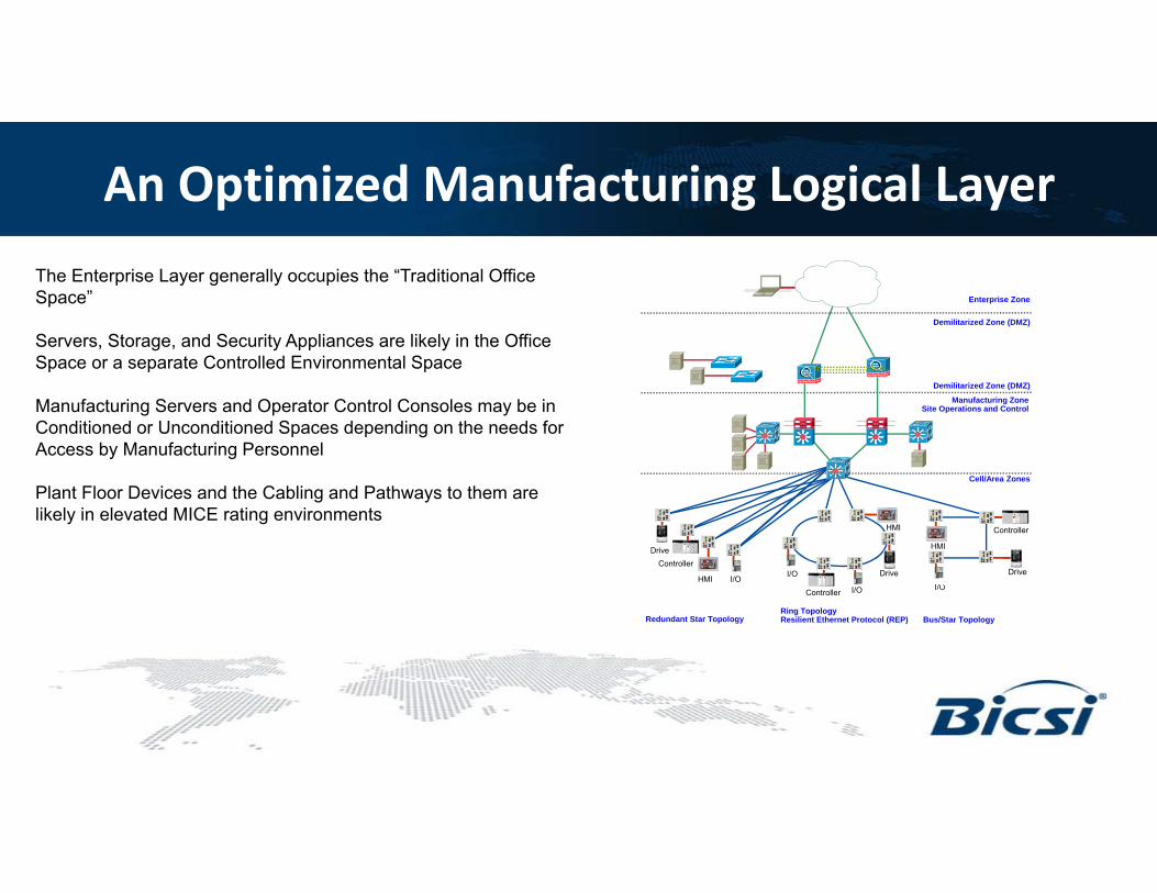
An Optimized Manufacturing Logical Layer
I/O
HMI
Redundant Star Topology Bus/Star Topology
Cell/Area Zones
Demilitarized Zone (DMZ)
Demilitarized Zone (DMZ)
Enterprise Zone
Manufacturing Zone Site Operations and Control
DriveController
HMII/O
Controller
Drive
Controller
Drive
HMI
Ring TopologyResilient Ethernet Protocol (REP)
I/O I/O
The Enterprise Layer generally occupies the “Traditional Office Space”
Servers, Storage, and Security Appliances are likely in the Office Space or a separate Controlled Environmental Space
Manufacturing Servers and Operator Control Consoles may be in Conditioned or Unconditioned Spaces depending on the needs for Access by Manufacturing Personnel
Plant Floor Devices and the Cabling and Pathways to them are likely in elevated MICE rating environments

An Optimized Manufacturing Logical Layer
These typical Layers will likely be identifiable in a Manufacturing Plant organized in “Converged Plantwide Ethernet” (CWPE),“Industrial Internet Of Things”(IIOT), or “Factory 4.0” Topology.
What is common to all is that a “flat network” with a single collision domain will not support high performance real time control over Ethernet networks with large numbers of nodes.
This makes a “Zone Topology” even more desirable from a performance standpoint where High Speed Packaging, Multi-Axis Motion Control, Safety, or Robotics are in use.

A Closer Look at the Manufacturing Logical LayerIn order to provide cabling and pathways for the plant floor, the designer and installers need to understand the Logical layer design• Is redundancy to be used
1. At which logical layera) Core Switchesb) Application Layer Switchesc) Control or Equipment Panelsd) Edge Devices (Automation Equipment)
2. What Topology is to be used (typical relationships)a) Redundant Star (Parallel Redundancy Protocol)b) Ring (Redundant Ethernet or Media Redundancy)c) Mesh (Spanning Tree or Rapid Spanning Tree)d) Linear (Beacon Redundancy or Parallel Redundancy)
3. Degree of Separation of Mediaa) Multiple Fiber Strands or Copper Pairs in same cableb) Separate Cables in Shared Pathwayc) Spatially Separate Pathways and Cabling
Redundant RingMesh Topology

Applying MICE Levels into Designs“IN-Solutions”

MICE Levels and Areas IN the plant“IN-Solutions” • “In-Room”
a) Few Mechanical Hazardsb) Chemicals likely well containedc) Limited Powerd) May be Temperature Controlled
• “In-Route”a) Potentially exposed to mechanical stress during installation
and useb) May be in proximity to Large Power Conductors
• “In-Panel”a) May be at elevated temperaturesb) Likely exposed to Noise Sources
• “In-Field”a) Likely exposed to continuous Mechanical Stressb) Potentially exposed to Liquids or Fine Particlesc) Often subject to Chemicals or Lubricants

Focus on elevated MICE Levels within Designs
CONTROL ROOM
CONTROL PNLZW
ELD
ING
R
OB
OTS
ZONE ENCLOSURE
PURCHASINGMDC
CAD ENGINEERING
LOBBY
MENSSALES
LADIESSTORAGE ROOM
CP
Z
CP
BORING MILL
3-TON CRANE
60” CNC MILL
SHOP SUPERVISOR
UNIVERSAL ID/OD GRINDER 150 TON
TRYOUTPRESS
WET GRINDERSURFACE GRINDER
CP
MACHINE ASSEMBLY AREA
MACHINE ASSEMBLY AREA
Z
SHIPPING AND RECEIVING
ZAUTOMATED 48” CUTOFF
SAW
WIRE EDM MACHINES
CP
Z
DO ALLBANDSAW
BAR FEED BANDSAW
CP
MICE 2-2-2-1
MICE 3-2-3-3
MICE 2-1-3-2
MICE 1-1-1-3
MICE 1-1-1-1
MICE 3-1-2-3
MICE 3-3-3-3

Dielectric ArmoredFiber DistributionCable
DIN mount enclosure to break out and protect buffered fibers and create testable permanent links on distribution cable
LC to LC Jumpers to Ethernet Switch uplink
Copper patch panel and horizontal cable distribution
Industrial ArchitectureExample of Zone Enclosure for Industrial Applications

Life Safety Codes and their Objectives
• Life Safety Codes are Primarily concerned with preventing1. Serious Injury2. Loss of Life
• Using NFPA 70 (United States- National Electric Code) as an example, Effective Grounding and Bonding Systems are designed to protect individuals from electrical shock and fire by
1. Safely conducting current during a ground fault to open overcurrent devices to prevent fire2. Interrupting the flow of stray ground currents that may pose a fibrillation hazard to personnel3. Minimize the potential difference between points of touch or step that may cause electrocution4. Safely discharging Lightning or static electric to Earth

Designing Grounding and Bonding to Life Safety Codes
• Conductor types and sizes are selected based upon 1. Impedance at power distribution frequency (50-60 Hz) to provide for safe operation of ground fault protective devices2. Short term current carrying capacity for Lightning Protection
• Criteria Defined by these Codes and Enforced by Authorities Having Jurisdiction were not developed with the goal of1. Protection of equipment from damage due to transients or static discharge2. Guarding against impairment in Performance of Networks
a) Some standards for Functional Safety Systems, such as IEC 61508, address reliable performance of networks.b) Assessment and enforcement of these types of standards are generally not done by Building Inspection Authorities
i. This may be required by workplace safety rules, enforced by OSHA, MSHA, or similar agenciesii. Machine Level Assessment is by organizations such as TÜV

Telecommunications Bonding Systems
• Telecommunications Bonding Systems Standards are not Enforced by Building Officials unless incorporated into Life Safety Codes
• Objectives of Design and Installation by Standards1. Protection of equipment from damage due to transients or static discharge2. Guarding against impairment in Performance of Networks
• Examples of these standards1. TIA-607 Commercial Building Grounding (Earthing) and Bonding Requirements for Telecommunications2. EN50310 Application of equipotential bonding and earthing in buildings with information technology equipment3. CSA T527 Grounding and Bonding for Telecommunications in Commercial Buildings4. IEEE 1100 Recommended Practice for Powering and Grounding Electronic Equipment (The Emerald Book)5. BICSI TDMM Telecommunications Design Methods Manual

Bonding Systems Design and Acceptance
• Criteria for Design and Acceptance
1. TIA-607-B a) Size of Telecommunications Bonding Backbone conductor (gauge by length) per Paragraph 6.3.2,Table 1b) Verification of overall resistance, including terminations
2. TIA-568-C.0a) Difference in potential between Electrical Distribution and Telecommunications Bonding infrastructure at Equipment
Outlet of less than 1.0 V rms per paragraph 5.3.5

Traditional Noise Sources on the Plant Floor
• Direct Current Power Circuits used in processes such as Plating lines create large magnetic fields around conductors
1. Physical Isolation is often sufficient to reduce interference in cables which are stationary2. Capacitive coupling is rarely an issue
• “Normal Power Distribution” circuits operating at 50-60 Hz, with moderate harmonic distortion (primarily 3rd, 5th
, and 7th on 3 phase circuits powering equipment with non-linear inputs) can be classified as “Low Frequency”. 1. Physical Separation must be larger than DC circuits due to capacitive as well as electromagnetic
coupling2. Impedance of shielding and bonding infrastructure is relatively easy to control due to lower inductance
and skin effect in bonding conductors at those frequencies

Problematic Noise Sources on the Plant Floor
Advanced Automation and efforts at cost reduction achieved by more efficient use of electric power has resulted in large numbers of Power Conversion and Control devices on the plant floor, such as Motion Controllers and Variable Speed Drives.
• Power circuits derived from power conversion devices with high power switching structures may generate “High Frequency” noise, with major components in the 100Khz- 30Mhz range.
1. Shielding becomes more effective than physical separation, due to higher radiated and capacitive coupling.2. Bonding becomes more challenging, due to skin effect and increasing inductive impedance of conductors as
frequency increases
• Noise components at Higher Frequencies (100Mhz and above) become even more problematic1. Copper Network cable geometry becomes more important, using parameters such as Transverse Conversion
Loss to lower Normal Mode noise induced in pairs within signaling character rates

Sources of High Frequency Noise on the Plant Floor
• Power Switching Devices such as Pulse Width Modulated Variable Frequency Drives with Insulated Gate Bipolar Transistors illustrate the factors affecting copper network cabling in Manufacturing Facilities
1. Radiated Electromagnetic Noise from Motor Leadsa) Rapid Turn On of IGBTs (50 ns range) and Turn Off (250 ns range) result in continuous transients which cause high
peak voltages on motor leads that may be amplified by “Transmission Line Effect” on those leads.b) Result is noise in frequencies well above 100 Mhz.c) Coupling between Power Devices and nearby Network Cabling in control enclosures is significantd) Routing of Power and Network cabling outside of enclosures should take into account
i. Physical separation ii. Use of separate bonded metallic pathways where practical
2. Conducted Common Mode Noise on Copper Network Cabling due to Significant Current in Bonding Infrastructurea) Imbalance in Rotor Windings and Air Gap resulting in current flow through bearings and motor frameb) Capacitive imbalance in Stator Windings to motor framec) Gradual breakdown in Winding Insulation due to Corona Effectd) Motor lead capacitance to metal pathways

Noise Coupling to Network CablingModes of Coupling
WW-CPWP-14, Rev.1, 05/2011©2010 Panduit Corp. All rights reserved
Noise Coupling between power circuits and copper Network cabling can be reduced by:
• Physical Isolation1. Network cabling should be kept as short as possible2. Routing and Pathways should minimize parallel runs of
power and network cabling
• Effective Shielding1. In order to mitigate Magnetic Coupling, shields should
contain ferrous materials2. Capacitive coupling can be reduced with shields
constructed of any metals (e.g. non-ferrous or ferrous metals in foil or braided construction)

Magnitude of the Potential for Disruption The graph to the left illustrates the allowed coupled common mode noise signal in a 1000Base-T and 100Base-T system for a 100 meter channel.
Note that 100Base-T cable cannot tolerate more than 0.5V of noise coupling near 100 MHz with the 1000BaseT tolerating much less only 0.1V. A VFD, servo, or inductive load with spikes in hundreds of volts could easily couple in noise at these low levels leading to disrupted communications.
Source: WW-CPWP-14, Rev.1, 05/2011 Optimizing Control Panel Layouts for Noise Mitigation in Factory Automation Systems © Panduit Corp.
Bonding of Network Cable Shields
• EN50174 Information technology- Cabling installation Part 2: Installation planning and practices inside buildings provides the following guidelines regarding Screened (Shielded) cables
• Paragraph 4.7.1.2 “The screen shall be continuous from the transmitter to the receiver”
• Paragraph 5.3.6.3 “Cable screens shall be terminated at each termination point to maintain the intended performance”
• EN50174 Information technology- Cabling installation Part 3: Installation planning and practices outside buildings provides the following guidelines regarding Screened (Shielded) cables
• Paragraph 5.6.4 “Metallic parts (e.g. screens, suspension or catenary wires) and metallic cable management systems should be connected to earth at both ends and every earthed cabinet.”

“Single Point” Bonding of Shields• Often times the term “Single Point Ground” is used where there is a known difference in potential between bonding points at each
end of a network segment. Typically one end of the shield is bonded through a parallel resistor-capacitor network within the connected device (that provides a high DC resistance and low AC impedance bonding connection) with the other end through a solidmetallic bond between the shield and “local” bonding point.
• A common example of this situation might occur where a cathodic protection system is applied to a buried pipeline for corrosion protection.
• This terminology tends to confuse the reader, leaving the impression that fully isolating a shield on one end of an Ethernet network segment is a recommended practice.
Example of Shield Bonding on network segment which terminates at points which are not at Equal Potential
Solid Metallic BondRC Network Bond with Metal Oxide Varistor to limit the magnitude of difference in potential to safe levels
Device Termination

Mitigating Noise with Effective Bonding Infrastructure
• At frequencies above 60 hz, conductors begin to rise in Impedance (Ohms per Foot) per unit length• This is due largely to a phenomenon known as “skin effect” • The style of conductor construction, as well as cross section, has an effect on the impedance• In a solid conductor the current flows primarily in the portion of the illustration identified as δ,
which depends on the frequency of the current and the electrical and magnetic properties of the conductor.
• In copper conductors, the skin depth can be expected to fall at the square root of frequency.• Mitigation of skin effect favors the largest number of most finely stranded individual conductors
to construct a wire• This, in addition to the flexibility gained by a flat braided conductor, makes them ideal for use
in bonding straps within equipment enclosures."Skin depth" by Biezl - Own work. Licensed under Public Domain via Commons
FrequencySkin depth (μm)
6 Awg. Conductor Dia. (mm)
Percent Cross Section
60 Hz 8470 4.115 n/a10 kHz 660 4.115 16.04%100 kHz 210 4.115 5.10%1 MHz 66 4.115 1.60%10 MHz 21 4.115 0.51%100 MHz 6.6 4.115 0.16%
Uninsulated bonding straps Insulated bonding straps

SM
Understanding Grounding Systems Terminology
Earthing Grounding Bonding

SM
Continuous Bonding “From Device to Dirt”
• A Grounding and Bonding System should be:
1. Intentional2. Irreversible3. Visually Verifiable
Telecommunications Bonding System
Utility Entrance and Main Bonding point
TMGB
TGB

SM
Telecommunications Bonding shown in TDMM
• Some of the terminology used by plant floor equipment manufacturers varies from that used in Chapter 8 of the TDMM, however, the principles and objectives of bonding infrastructure are similar.
• Telecommunications Rooms may be replaced by Control or Switchgear Rooms with network equipment mounted in sealed, gasketed, enclosures in these spaces.
• Due to the likelihood of a large number of high power noise sources, and widespread use of copper network segments for network connections to those (and other networked devices in their vicinity) the effectiveness of the Bonding Infrastructure becomes even more critical than that in the Enterprise workspace.
• A low impedance bonding infrastructure must extend to the Equipment Outlet in control enclosures where both significant noise sources and sensitive network equipment are installed on the plant floor.

SM
Challenges Using Building Steel vs TBB
• Many older Industrial Buildings may have been constructed with Brick or Wood Framing.
• Steel Framing added for Seismic Retrofit or remodeling may be isolated from other steel building elements.
• Modern Food Processing facilities (or others with refrigerated or controlled atmospheric spaces) may have entire rooms fabricated from steel panels with foam cores that are not a part of the building structure.
• Verification of the long term integrity of the steel infrastructure as the bonding means may be difficult.
• These factors may favor the use of a copper conductor as the Telecommunications Bonding Backbone.
• Fine Stranded Conductors may be more suitable than standard “Code Conductor” stranding
• TBB conductors run in metallic conduit must be bonded to both ends of the conduit
Ultra Fine Strand often 66 or more strands
Fine Strand typically 19 strands
Standard Strandingusually 7 strands
With finer individual strands, skin effect has less overall effect in reducing effectiveness at higher frequencies

SM
Continuous Bonding Throughout the Facility
• 70–108 NATIONAL ELECTRICAL CODE 2014 Edition
250.6 ARTICLE 250—GROUNDING AND BONDING
(B) Alterations to Stop Objectionable Current.If the use of multiple grounding connections results in objectionable current, one or more of the following
alterations shall be permitted to be made, provided that the requirements of 250.4(A)(5) or (B)(4) are met:(1) Discontinue one or more but not all of such grounding connections.(2) Change the locations of the grounding connections.(3) Interrupt the continuity of the conductor or conductive path causing the objectionable current.(4) Take other suitable remedial and approved action.
(D) Limitations to Permissible Alterations. The provisions of this section shall not be considered as permitting electronic equipment from being operated on
ac systems or branch circuits that are not connected to an equipment grounding conductor as required by this article. Currents that introduce noise or data errors in electronic equipment shall not be considered the objectionable currents addressed in this section.
(E) Isolation of Objectionable Direct-Current Ground Currents.Where isolation of objectionable dc ground currents from cathodic protection systems is required, a listed ac
coupling/dc isolating device shall be permitted in the equipment grounding conductor path to provide an effective return path for ac ground-fault current while blocking dc current.

SM
Physical Network Cable Routing inside Equipment
• Begin by segregating the equipment and bonding the ground plane
• Add duct in such a way that you can maintain wire segregation between “clean”, “dirty” and “very-dirty”
• Add shielding in appropriate places where segregation cannot be achieved by distance
Wire & Equip Segregation – Noise Zones
PWM Drive
PWM Drive
PAC
PSU
Noise
Noise
Sens
itive
Sens
itive
Relay Relay
Main Panel(Front View)
Right Side Panel(Inside View)
PWM Drive
PWM Drive
Segregation from Dirty Duct
Very-Dirty Zone(Black Duct)
Dirty Zone (Grey Duct)
Clean Zone (White Duct)

SM
Network Cable Requirements inside Equipment and Control Panels
• Where cable is terminated in control devices attention must be paid to the voltage rating of the cable jacket
1. Ethernet cables may be rated at 300 Volts
a) The voltage rating may be marked on the cable jacket
b) UL Listed type CM cable is rated 300 Volts, unless marked otherwise
i. Ref: NFPA Article 800.179 Communications Wires and Cables
c) This type of cable (and patch cords) is suitable where no other cables in the enclosure are labeled at higher voltage (e.g. 600 Volts)
• Ethernet cables near power or control cables rated 600 volts should have a 600 volt rating clearly visible on the cable jacket
• Network cables should cross power conductors at right angles and not be routed alongside them
480V Motor and VFD

SM
Network Cable Requirements between Equipment and Control Panels
• Copper Patch Cords interconnecting Equipment with Shielded Jacks must be Shielded
• Network cables which leave the cabinet to connect to Switches or Equipment outside the enclosure should be Shielded
1. Where practical, these should be treated as permanent link cables, terminated in shielded jacks at each end of the segment for testing purposes
a) DIN rail and Panel Mount Patch Panels are available which accommodate a single or multiple jacks
b) Bonding jumpers are available where equipment does not provide bonding of the shield
2. If cabling is Direct Connected (Plugs on one or both ends of cable)
a) Shielded plugs should be usedb) Cable should have stranded conductorsc) Plugs should be designed for use with stranded
conductors
Plant Floor Network and Control Equipment Cabinets
Industrial Network Switch Networked
MCC

SM
Bonding Inside Equipment and Control Panels
Bonding Design Principals
1. Use electrogalvanized (rather than painted) equipment mounting panels
2. Bond equipment panels and doors using flat braided jumpers
3. Provide an adequately sized Bonding Bus Bar properly terminated to the branch circuit and telecommunications bonding and equalizing conductors

SM
Bonding Metallic Armor in Cables
770.114 Grounding. Non–current-carrying conductivemembers of optical fiber cables shall be bonded to a groundedequipment rack or enclosure, or grounded in accordance withthe grounding methods specified by 770.100(B)(2).
770.180 Grounding Devices. Where bonding or groundingis required, devices used to connect a shield, a sheath,or non–current-carrying metallic members of a cable to abonding conductor or grounding electrode conductor shallbe listed or be part of listed equipment.

Generic and Industrial Standards Throughout the World
Region of the WorldNorth and
South America
Europe, Other Areas
of World
Europe (Cenelec)
Generic Premise Cabling Standard
ANSI / TIA-568 Series
IEC / ISO 11801Series EN 50173-1
Industrial Premises Cabling Standard
ANSI / TIA-1005-A IEC / ISO 24702 EN 50173-3

Applicable Industrial Cabling StandardsTelecommunications Standards
• TIA/EIA-568-C defines cabling types, distances, connectors, cable system architectures, cable termination standards and performance characteristics, cable installation requirements and methods of testing installed cable
• C.0 and C.1 have recently been superseded by 568.0-D and 568.1-D respectively
• 0-D defines the overall premises infrastructure for copper and fiber cabling
• C.2 addresses components of copper cable systems• C.3 addresses components of fiber optic cable systems• ANSI/TIA-1005 is a specific standard for Industrial premises
and is explicitly supported by the 568-C cabling standard

• Developed by the TIA TR-42.9 Industrial Infrastructure Subcommittee and published in May 2012. Standard provides infrastructure, distance, telecommunications outlet/connector configuration, and topology requirements for cabling deployed in industrial environments.• Industrial Areas• Telecommunications Spaces• Telecommunications Pathways• Firestopping• Backbone Cabling • Horizontal Cabling • Work Area• Grounding and Bonding• Industrial Cabling Performance Requirements
Industrial PremisesTelecommunications Standards

• M12 D-code• M12 X-code• > 4 connector channel• Coupler / Adaptor• MICE ratings
Some Key Variations of TIA-1005-A from TIA-568 Series
• Note – TIA-1005-A was published in May 2012. The M12 X-code connector system is described in TIA-1005-A-1, published in January 2015.

M12 D-code4 pin connector, keyed2 Pair cable used10/100 Mbit/second capabilityField terminable M12 plug shown to rightSuitable for STP or UTP cableCable type – 22 to 26 awg conductors; stranded or solidCable diameters 4.5 to 8.8 mm (0.18 to 0.35 inches)Interface conforms to IEC-61076-2-101 stdWhen mated will meet IP65 / IP67 requirements
M12 D code
Connection End
Cable End

M12 X-code8 pin connector, keyed4 Pair cable usedConnector design uses separated pairs, hence is a high
data rate connectorConnector will support 10 Gbit/sec, but currently used in
Ethernet/IP deployments to support 1 GbpsSuitable for STP or UTP cableInterface conforms to IEC-61076-2-109 standardWhen mated will meet IP65 and IP67 requirements
M12 X-code

• Although not recommended, TIA-1005-A gives the option of using more than 4 connectors in a channel
• For 5 or 6 connectors in the channel, Category 5e or Category 6 performance can be obtained using Category 5e or Category 6 cable respectively, along with connecting hardware having improved Return Loss and NEXT
• It is expected that the connecting hardware may have to be rated as Category 6A performance
> 4 Connector Channel

Coupler / Adaptor
Industrial Bulkhead RJ45 to RJ45 Coupler
L < 100 mmOne Connection
L > 100 mmTwo Connections
TIA-1005 provisions for the use of the coupler or adaptor. These are often used to transition cabling from inside the enclosure (typically IP20 environment) to outside the enclosure (typically IP67 environment)
L
L

Adaptor
Female M12 D-Code End
Female RJ45 Shielded End
RJ45 to M12 D-code Adaptor
L
Typically used to transition between IP20 environment inside the enclosure to an IP67 environment outside the enclosure
If 4 pair cable is used with the RJ45, the adaptor needs to include 100 ohm termination
resistors for pins 4 to 5 and 7 to 8

IP Ratings
Reference Table of IP rating Code1 st Digit
Solid Object Penetration 2 nd Digit
Liquid Protection
0 No protection 0 No protection
1 Protected against solid objects greater than 50 mm 1 Protected against vertically dripping water
2 Protected against solid objects greater than 12.5 mm 2 Protected against dripping water when inclined up to 15 degrees
3 Protected against solid objects greater than 2.5 mm 3 Protected against spraying water
4 Protected against solid objects greater than 1.0 mm 4 Protected against splashing water
5 Protected against ingress of dust 5 Protected against jetted water
6 Dust tight 6 Protected against powerfully jetted water
7 Protected against temporary immersion in water
8 Protected against continuous immersion in water
Note: IP69K rating has been introduced for food, beverage, etc. washdown. Based on high temp, high pressure power wash.
StandardIEC 60529

• Industrial Networks Must take into consideration the physical challenges of the facilities environment
• Location, routing and equipment choices should be based on the complete understanding of cause and effect conditions
• Environmental Focus– M.I.C.E. (TIA-1005)
Cable Selection ProcessReal World Considerations
SensorDrive
I/O
Plant EthernetController
Switch
Ethernet

Office Industrial
Increased Environmental Severity
Electro-magnetic
ClimaticChemical
Ingress• Water• Dust
Mechanical• Shock• Vibration
E1
C1
I1
M1
E2
C2
I2
M2
E3
C3
I3
M3
(TIA-1005-A)
Cable Selection ProcessM.I.C.E. Describes Real World Challenges

Target ApplicationsWhen to Use Copper Cabling Systems
• Runs equal to or shorter than 100 meters – when following TIA channel model
• Derating factor likely to be required when using stranded cable• Copper cabling has long history of successful installation• Most cost effective media when shorter runs are required• Twisted pair copper cabling has the ability to support power
for Power over Ethernet applications

68
Break- 15 Minutes
Please return early, so that we can restart promptly.

Copper Cable Categories Comparison
ANSI/TIA-568-C.2 - ISO 11801 Cat5e - Class D Cat6 - Class E Cat6A - Class Ea
Construction UTP or STP UTP or STP UTP or STP
Specified Bandwidth 100 MHz 250 MHz 500 MHz
I L @ 100 MHz 24.0 dB 21.7 dB 20.9 dB
NEXT @ 100 MHz 30.1 dB 39.9 dB 39.9 dB
Cable Wire Gauge 24 AWG 24 or 23 AWG 23 AWG
POE Support Yes Yes Yes
Ethernet Channel Reach: 10G/1000BASE-T
Gigabit Ethernet 100 m 100 m 100m10Gigabit Ethernet Not supported 37 m (UTP) 100 m
ISO/IEC 14165-144 Not supported Not supported Not supported
Broadband CATV Not supported Not supported Not supported
Approx. Relative Installed Cost 1.0X 1.2 X 1.5X

• Covers Electrical Performance Requirements for Cat 3, 5e, 6, 6A cables– Cat 3 – Up to 16 MHz– Cat 5e – Up to 100 MHz– Cat 6 – Up to 250 MHz– Cat 6A – Up to 500 MHz
• Applies to both 100 ohm UTP & STP• Test configurations
– Basic Link (Cable), Permanent Link and Channel
TIA-568 Series – Key Cables Types
Note: Cat 3 cable was removed fromANSI/TIA-568-0.D, but is still referred to in ANSI/TIA-568-C.2

Channel Performance With Different Category Components
Category of Modular Connecting Hardware
Category 5e Category 6 Category 6AModular Plugs and Cords Performance
Category 5e Category 5e Category 5e Category 5e
Category 6 Category 5e Category 6 Category 6
Category 6A Category 5e Category 6 Category 6A
Table showing the backwards compatibility of different category cable, plugs and cords

TIA 1005-A Channel for Industrial Premise Cabling
Equipment Equipment
Permanent Link Under TestExample – LAN switchExample – VFD (Variable
Frequency Drive) in a Control Panel
Cables and CordsEquipment Cord (Patch Cords)……………..FOptional Consolidation Point Cabling………BHorizontal Cabling……………………………C
Connecting hardwareAutomation Outlet……………………………..AOOptional Consolidation Point Connector……CPHorizontal Cross-connect or interconnect.....C1
Maximum LengthB + C………………….90 m (295 ft)
F FB C
AO CP C1
Note: The AO (Automation Outlet) is called the EO (Equipment Outlet) in the Generic ANSI/TIA-568 Series

Copper Cable Construction Overview
UTP Type STP Types

Horizontal Cable Flame Ratings
• General Purpose CM• Riser CMR• Plenum CMP• Low Smoke Zero Halogen LSZH-1
(IEC 60332-1)• Low Smoke Zero Halogen LSZH-3
(IEC 60332-3)
Other Applicable IEC Standards:• IEC 60754-1 – Amount of Acidic
Gases• IEC 60754-2 – Degree of Acidity of
Gases• IEC 61034 – Smoke Density
The Construction Products Regulations are going to be introduced in Eu. Products must display CE marking by June 2017

Horizontal Cable Flame Ratings
CMX CM CMR CMP LSZH -1 LSZH-3
UL 1581 UL 1685 UL 1666 NFPA 262 IEC 60332-1 IEC 60332-3CSA FT1 CSA FT4 CSA FT6 IEC 60754 IEC 60754
IEC 61034 IEC 61034PVC PE x x
FRPVC HDPE x x xFRPVC FEP x
Polyolefin HDPE xPolyolefin HDPE x
Jacket Insulation

Industrial Environment Cable Jacket Comparison
Types of Cable JacketFunction PVC TPE PUROil resistance Good Very good Very goodAbrasion resistance
Good Very Good Excellent
High Flex Applications
Good Excellent Excellent
Smoke rating CM CM CMX Outdoor
Zero halogen (IEC 60332-1)
Relative cost $ $$$ $$$

Target ApplicationsWhen to Use Fiber
• Switch to switch links in Resilient Ethernet Protocol – High availability
• Uplinks requiring higher bandwidth capabilities and extended length
• Applications requiring low convergence times - process• High security applications - fiber is intrinsically secure• Environments with high EMI/noise• Level 2 requirements (No spark generation)

Selecting the Right Fiber requires…
• Knowing the Equipment and network you are connecting to.
• Knowing the Distance Requirements/Bandwidth/Fiber Count and Type of Fiber.
• Understanding the Application Environment.

Knowing the Capability of your Equipment
The Equipment – The first step in choosing the right fiber is to look at the capability of your equipment.
• Look at the specifications of the equipment to determine the speed of the connections.
• What ever Fiber you choose should at least be able to handle the fastest mode of the existing system.

Knowing the Capability of your Equipment
The Stratix is a good switch to use as an example because it has both Uplink ports and Data ports running at different speeds.
• The uplink port speed is determined by the use of copper or fiber. If it’s fiber the configuration of the “SFP” module determines the speed of the system.
SFP Stands for “Small Form Pluggable” Module

Knowing the Capability of your Equipment
The Stratix is a good switch to use as an example because it has both Uplink ports and Data ports running at different speeds.
SFP Stands for “Small Form Pluggable” Module
SFP Stands for “Small Form Pluggable” Module

Industrial Automation equipment vendors are starting to offer SFP receptacles on switches for EtherNet (uplinks typically).
The optical receptacle on the SFP for Gb/s Ethernet is defined as an LC interface. Most major transceiver vendors, now sell SFPs with the LC interface only. The LC is the market leader in SFF* connectors. Other connectors such as SC, ST, etc. will be found on other equipment, especially legacy
.
1GBASE-SX SFP Modular Transceiver SFF FOCIS-10 LC Connector
MDI – Media Device Interface (LC Duplex Receptacle)
Industrial ComponentsApplicable Fiber Connectors for EtherNet/IP
* SFF – Small Form Factor

Understanding your Expansion or Upgrade Path
The following is an example list of specifications for the fiber-optic SFP module connections. Each port must match the wave-length specifications on the other end of the cable, and for reliable communication, the cable must not exceed the rated maximum cable length.
SFP ModuleType
Cat. No. Wavelength(nm)
Fiber Type Core Size/CladdingSize (micron)
Cable Distance
100BASE-FX 1783-SFP100FX
850 MMF 50/12562.5/125
2 km (6562 ft)2 km (6562 ft)
100BASE-LX 1783-SFP100LX
1310 SMF G.6522 10 km (32,810 ft)
1000BASE-SX 1783-SFP1GSX
850 MMF 62.5/12562.5/12550/12550/125
220 m (722 ft)275 m (902 ft))500 m (1640 ft)550 m (1804 ft)
1000BASE-LX/LH 1783-SFP1GLX
1310 SMF G.6522 10 km (32,810 ft)
Single Mode Fiber - Short Runs
• The optical transmit power for single mode fiber runs is significantly higher than the power used for multimode fiber runs (laser versus VCSEL) – can be typically 10 dB.
• In legacy systems especially for short single mode fiber runs, attention has to be paid to ensuring receiver maximum input threshold is not exceeded.
• Use of an optical in-line attenuator may be required for short single mode runs.

Now That we Understand the Equipment, We Must Begin to Understand Fiber Selection Criteria
• The considerations for selection of fiber are:– Type of cable and bandwidth – single mode fiber (SMF) or multimode fiber (MMF)– Fiber count– Jacket rating and type– Application– Environmental construction– Type of connector being used– Loss budgets

How the Optical Multimode (OM)/Optical Single mode (OS) ratings equate to Distance
Multimode Single-mode
62.5/125µmOM1
(λ = 850nm)
50/125µmOM2
(λ = 850nm)
50/125µmOM3 / OM4(λ = 850nm)
OS1, OS2(λ = 1310nm)
Ethernet 1000BASE-SX
Channel Attenuation (dB) 2.6 3.6 4.5 --
Supportable Distance m (ft)
275(900)
550(1804)
800(2625) --
Ethernet 1000BASE-LX
Channel Attenuation (dB) -- -- -- 4.5
Supportable Distance m (ft) -- -- -- 5000
(16405)
Table data from ANSI/TIA-568-C.0 (D.3)

Fiber Optic Link Budget

• Channel designed around connector Insertion Loss of 1.5dB max (2 connectors of 1.5dB each max.)
• Possible to have higher levels of IL in the 1000BASE-SX channel
• May desire higher #s of connectors in channel or allow for simpler (and higher loss) connectors to be used
SFF Electronics & Medium Dependent Interface (MDI) IEEE 802.3z - 1000BASE-SX
550m
275m

What makes up a Fiber Cable?
The Cable – There are two classes of fiber in use today.• Single Mode – Long Distance Fiber, more expensive hardware technology • Multi Mode – Shorter Distance, more cost effective for inside plant use.
• To understand the differences between core sizes, and why they matter, you need to know what makes up a fiber cable.
During construction, the cladding is given a coating of acrylate

Just How big is a MICRON anyway?
MICRON0.000039”0.001mm
The average human hair is 89 times larger than a Micron !
Average Human Hair .0035” or .0889mm
.001” Inch0.0254mm
.0001” Inch0.00254mm

Single Mode Fiber
9µm
All sizes expressed In Microns
125µm

All sizes expressed In Microns
5062.5
125
Multi-Mode Fiber (62.5 and 50 micron)
OM1 Fiber Schematic OM2, OM3, OM4 Fiber Schematic

230
All sizes expressed In Microns
5062.5 200
Polymer Coated Multi-mode Fiber (PCF)
Note: PCF is not the same as POF –Plastic Optical Fiber

How big is the fiber, (relatively)?
9230µm
** All sizes expressed In Microns
5062.5
125µm
200µm
Cladding
Core
Buffer
Core size will tell you the OMx of the Fiber

Plastic Optical Fiber (POF)
POF is a large core optical fiber made of Poly(methyl methacrylate) (PMMA), which is a transparent thermoplastic used as a lightweight or shatter-resistant alternative to glass. Has relatively good optical properties.
Mature technology and in wide use for automotive interconnects, Home networks in Europe and Asia, and audio/video interconnection for over 25 years.
Restricted to short reach applications due to limited bandwidth and high attenuation. Some advantages:
• Utilizes very low cost LEDs and silicon detectors• Ease of handling and termination (lowest cost termination)• Large tolerances reduce termination time with simple tools• Low precision enables low cost manufacturing
95
Work underway within the IEEE to define performance for 15 and 40 meter channels supporting 1 Gbps data rates
Cable focusing on IEC 60793-2-40, Type A4a.2

POF
Core
Cladding
PCF
MMF SMF
980/1000 µm
200/230 µm(also std MMF sizes)
50/125 µm 9/125 µm
Optical Fiber Cross Sectional Areas (scaled)

What do the OM ratings mean?
If you see OM in the Fiber grade it always means Multi-Mode. – The US Adopted a Grading System Invented By ISO, The International Standards Organization in Geneva, Switzerland. The
“Optical Multimode” Rating System
• “OM 1” --- 62.5 Micron (Mostly legacy systems)• “OM 2” --- 50 Micron (plain vanilla variety)• “OM 3” --- 50 Micron (Laser optimized to work with Vertical Cavity Surface Emitting Lasers or VCSELs)• “OM 4” --- 50 micron (Extended Bandwidth – Further refined to reduce pulse spreading and enable longer
distances)
• And just like with Copper Categories – A bigger number means better cable!

What do the OS ratings mean?
If you see OS in the Fiber grade it always means Single-Mode. • OS 1• Maximum attenuation, dB/km (ISO 11801)
– 1.0 dB/km at 1310 nm– Not specified at 1383 nm– 1.0 dB/km at 1550 nm
• Typical maximum reach: 2 km• Generally suited for indoor use only• Tight buffer construction
• OS 2• Maximum attenuation, dB/km (ISO 11801)
– 0.4 dB/km at 1310 nm– 0.4 dB/km at 1383 nm– 0.4 dB/km at 1550 nm
• Typical maximum reach: 10 km• Suited for indoor and outdoor use• Loose tube construction
• Typical single mode fiber today is designated OS1 / OS2• Legacy OS1 has water absorption ‘peaks’, one of which occurs at 1383 nm• Low water peak fiber types are commonly available, as seen in OS2 specification• OS2 is suitable for Coarse Wave Division Multiplexing application across the 1310 to
1625 nm band

• Optical fiber systems deployed in LAN applications don’t use the same fiber for transmit and receive.
• This means the transmit port of one piece of equipment has to be connected to the receive port on the neighbor – commonly referred by the terms A to B.
• The A to B connection has to be made in the permanent link as well as patch cords.
Optical Fiber - A to B
Duplex Fiber Patch Cord

• Gigabit transmission over legacy OM1 / OM2 fiber can reach channel lengths of up to 275 m and 550 m respectively, using 850 nm transceivers.
• Using 1300 nm transceivers and Mode Conditioning Patch Cord (MCPC) can extend channel length to 550 m for legacy OM1 / improve link margin for 550 m maximum length for OM2.
• The MCPC incorporates an offset splice of single mode to multimode optical fiber transition to give effective launching into the multimode fiber
Mode Conditioning Optical Fiber Patch Cords

Optical Fiber Jacket Colors
• Most fibers are marked with the fiber diameters on the jacket, but often hard to read when installed. Especially the case in an Industrial environment
• Color coding standardized for cables containing each type of fiber: Yellow – Singlemode Orange – Multi mode – OM1 and OM2 Aqua – Multi-mode – OM3 and OM4
• Note - In Europe and with the U.S. military, 50/125 is orange and 62.5/125 is gray.

Optical Fiber Construction – Tight Buffered vs. Loose Tube
• 250 micron fibers are contained, e.g. ‘float’ in tubes• Tubes contain gel or absorbent tape to protect fibers
from water ingress• Suited for outdoor use – to prevent stress on the
fiber arising from wide temperature swings• Suited for high vibration environments• Fanout kit required to protect fibers and ease
termination
• PVC buffer extruded onto fiber coating• Typical diameter is 900 micron• Cable is more flexible and easy to terminate• Most common indoor cable type• Riser and plenum types available
Coated Fiber
Buffer
ThermoplasticTube
Moisture Blocking Gel
900 µmDiameter
250 µmDiameter

Industrial ComponentsFiber Media
The capability of each fiber in terms of its bandwidth (and reach) is a function of transceiver type and the optical properties of the fiber used
Fiber is used commonly in the following situations:
• Applications requiring faster convergence for network resiliency recovering from faults/changes• Outdoor or between buildings• When the distance is beyond the reach of copper (100m)• For immunity from electromagnetic interference (EMI)
Singlemode fiber electronics are much more expensive than multimode equivalents and are generally deployed in long reach applications that are beyond the capability of their multimode counterparts. Also, fibers with a smaller multimode core size (50μm vs. 62.5μm) support higher bandwidth and longer reach applications.

Cable Selection ProcessApplications for ‘Indoor’ Fiber
Indoor Fiber DistributionUsed when you have
sufficient protection for the fiber
Indoor Interlocking ArmorUsed when the fiber has to
protect itself
Indoor/Outdoor Polymer Clad Fiber“Electrician Friendly” crimp on connector
for direct connect node to node
Indoor Dielectric Armored FiberAll the benefits of an armored fiber without the metal. Use in
area suspected of unequal potential grounds

Optical Fiber ApplicationsIndustrial Architecture Deployment Areas

Optical Fiber ApplicationsBackBone Cabling Systems

• Interlocking aluminum armor eliminates the need for inner duct or conduit to provide a smaller crush resistant pathway for design flexibility and a lower installed cost
• Available in 6, 12, 24, 36, 48, 72, 96, and 144-fiber counts• Multimode (OM4, OM3, OM2, and OM1) and Single mode
(OS1/OS2) fiber available • Sheath markings provide positive identification, quality
traceability, and length verification• 900μm standards-based color-coded buffer coating
protects fibers during handling and allows for easy identification and stripping
BackBone CablingMetallic Interlocking Armor Cables

BackBone CablingInterlocking Armor Cable Deployment
Don’t route cabling along existingConduits or buildingStructures using cable ties

Crush-Resistant Dielectric Armor
Distribution-style Cable Core
BackBone CablingDielectric Armored Cables
All-Dielectric Armored Cable
• Lightweight & crush resistant
• Smaller bend radius than metallic interlock armor
• Can be deployed without conduit (J-hooks, undefined pathway)
• No grounding/bonding required
• Available in fiber counts & types supporting switch requirements

Optical Fiber – Connector Types

Breakout Cable
Zip Cord Cable
PCF Cabling Systems
• PCF Graded Index Fiber Cable
• Industrial networks operating at 10/100 max. require either a graded index OM1 or OM2 fiber
• A version of 200/230 PCF fiber with either an OM1 or OM2 fiber in the core has been developed recently (62.5/200/230 & 50/200/230)
• These fibers are supplied in a duplex zip cord cable and a 2-fiber and 4-fiber breakout cable
• The duplex zip cord cable does not have the aramid yarn that we find in standard 50/125µm zip cord cables since the connector is crimped directly onto the PCF fiber

Solution/Product Overview“Electrician Friendly” PCF LC Connector
LC Connector for PCF Graded Index Fiber • Device level of network (machine level) there is need for LC connectivity
to provide direct-attach builds (direct to equipment)• Current field-termination technologies, epoxy-polish & Cam, require a
degree of cleanliness and training that is not found by typical installers in this space
• Can be field-installed by individuals with little or no training (maintenance, control panel builders & electricians)
• Total Installed Cost for PCF solution (for most installations does not require conduit) is significantly lower than standard fiber solutions (non-PCF) deployed in conduit
• Note – PCF terminations prepared in this way will not be suitable for use in structured cabling systems, using adapters to join to other LC connectors that have been field or factory polished, so these PCF assemblies are more suited to point to point cabling deployments

Solution/Product OverviewPCF Connector Termination
Load Connector into Crimper Prepare Cable Subunit Insert Fiber
Crimp Fiber Cleave Fiber Mount Backshell/Boot
1 2 3
4 5 6

Optical Fiber Mismatch
• Some industrial automation deployments are using legacy OM1 fiber
• Newer fiber types can mean there is a desire to connect to OM2 or higher category types
• A mismatch exists between the cores of a connection of OM1 to OM2, or higher
• OM1 core diameter 62.5 micron• OM2, .. Core diameter 50 micron• Transmission path direction OM2 to OM1 results in several
tenths of a dB loss• Transmission path direction OM1 to OM2 results in 3 to 4 dB
loss• Since data transfer is bi-directional, the higher ‘hit’ will be
taken• Possibility of mismatch to legacy installs can make a new
install less unpalatable
Energy in core of OM1 fiber does not all transfer to 50
micron fiber
Psst. By the way – just in case you’re wondering, connecting a multi-mode to singlemode optical fiber will result in a REAL BIG loss, > 20 dB
OM2 OM1 OM1 OM2

Cable Plant ValidationTools for Fiber Cabling Commissioning and Troubleshooting
Permanent Link Qualification• Provides light source power meter testing of
permanent links• Validates against TIA 568-C expectations• Measurements against warranty
Fiber Troubleshooters • Identifies connections with high loss• Finds connectors with high reflectance• Identification of multiple events/issues• Identifies fibers longer than intended
Inspection & Cleaning • Easiest network performance solutions• Provides visibility into ports and end faces• Easy one click cleaning

Summary – Factors Influencing the Choice of Fiber Type
Consideration Assessment Design Impacts
Connectivity CountNumber of Devices, Machines, etc.
Cable Runs, Pathway Capacity, Port Count, etc.
EnvironmentMechanical, Ingress, Climatic/ Chemical, Electro Magnetic
Protection, Separation, Transmission Media (Cu vs. Fiber)
BandwidthCurrent Network Utilization & FutureLoad
Cable Media, Switches, Installation
Cable ReachCable Length Cable Media, Switches
SafetyNearby High Voltage Device Access, Protection
SecurityThreat Level, Isolation Port Protection, Access,
LongevityYears of Service Bandwidth, Hardening, Manufacturing
Growth

Summary – Best Practices
• Adoption of Converged Plantwide Ethernet topology• Standards based designs• Zone topology• Identify target uses for optical fiber• Select the right copper cabling
– Future Proof – consider the data needs of tomorrow, not just today– Consideration of the environment using the MICE criteria
• Select the right fiber cabling:– Know the equipment and network you’re connecting to– Distance requirements / Bandwidth / Fiber counts– Understand the application environment
• Measure permanent link performance

Pathways
• Agenda– Purposes– Benefits– Types
• Solid tray• Grid basket• Ladder rack• J Hooks
– Comparison Table - When would you use one versus another?

What Is a Pathway?A pathway is the foundation for good cablingCharacteristics of a pathway:• It defines the route from point A to point B• It may be an electrical conduit, a cable tray, J-Hooks, surface
raceway, or a combination of these itemsConsiderations for pathway choice• Each work area outlet should be connected to the
telecommunications room by a minimum of two cables; Category 5e (Class D) or higher
• The TIA-569 standard recommends that the pathway allows for 50% growth
– 2 cables x 10 WAs = 20 cables + 50% growth = 30 cables
119

ConduitConduit• Conduit should be run in the most direct route
possible along building lines
• Pull boxes should be spaced no greater than 98’ (30m) apart – note pull boxes not be used to change direction on fiber paths (use elbows only)
• No more than two 90o bends between pull boxes• Service no more than 3 outlet boxes• Cat6A cable increase conduit from ¾” to 1”
120
Pull Box

Cable / Basket TrayCable tray or ladder racks • Higher cable count than conduit• Install per manufacturer’s guidelines and loading
capacities• Metal trays and ladders must be properly bonded
and grounded• Put power and data cables in separate trays• Physical metal barriers must separate power and
data cabling in the same tray – 600 V rated cable myth
121
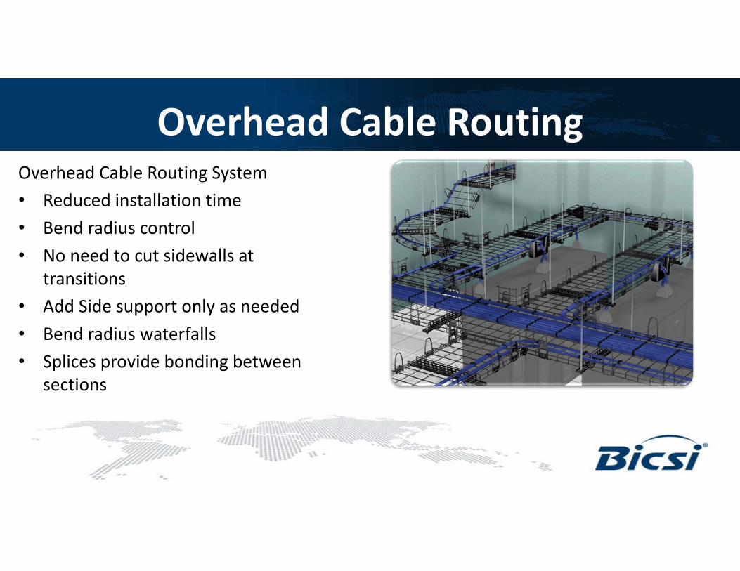
Overhead Cable RoutingOverhead Cable Routing System• Reduced installation time• Bend radius control• No need to cut sidewalls at
transitions• Add Side support only as needed• Bend radius waterfalls• Splices provide bonding between
sections

Standards – Pathways EdgesRegulatory standards prohibit sharp edges on cable pathways• NEC 392.100 (B) Construction Specifications - Smooth Edges:
“Cable trays shall not have sharp edges, burrs, or projections that could damage the insulation or jackets of the wiring”.
• NEMA VE2-2006 – Section 4.5.2 – Cutting“After cutting, smooth the cut edges to remove any burrs”
• TIA 569 - Installation: “The inside of the cable support system shall be free of burrs, sharp edges or projections that can damage cable insulation”

J-Hooks
• Placed at 4’ to 5’ intervals• Ensure a minimum of 3” clearance above
suspended ceiling• Typical fill for a 2” hook:
• 60 Category 5e• 50 Category 6• 25 Category 6A (generation 1)• 30 Category 6A (generation 2)

Proximity of Power Cabling to Data Cabling
• The location of data cabling close to power wiring is subject to national, local code etc. Example – see National Electrical Code (NEC) Article 725 (Class 1, Class 2 and Class 3 Remote-Control, Signaling and Power-Limited Circuits), Article 770 (Optical Fiber Cables and Raceways) and Article 800 (Communications Circuits) paragraph 133 (A) (2).
• Information about the spacing of telecommunications metallic (copper) data cabling from power cabling to limit the effects of power cabling on data transfer is given in several standards: ANSI/TIA-569-C - gives recommended separation distance from power wiring for balanced
twisted pair cabling for different data cable types (e.g. UTP, STP, etc.) and power wiring with different numbers of conductors, voltage level and current.EN 50174-2 – gives a formula based approach that gives the separation distance in terms of
cable management system, data cable performance, quantity and type of electrical circuit, etc.
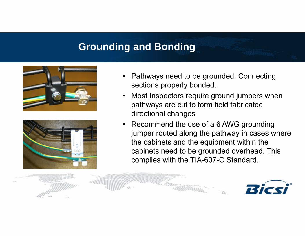
Grounding and Bonding
• Pathways need to be grounded. Connecting sections properly bonded.
• Most Inspectors require ground jumpers when pathways are cut to form field fabricated directional changes
• Recommend the use of a 6 AWG grounding jumper routed along the pathway in cases where the cabinets and the equipment within the cabinets need to be grounded overhead. This complies with the TIA-607-C Standard.

127
Pathways – Summary ComparisonPathway Type Conduit Duct / Raceway Grid type Pathway Ladder rack J Hooks
Support Given Continuous Continuous Point support, every ~ 3 inches
Point support, typically every 12 “
Point support, typically every 4 – 5 ft
Relative cost $$ $$$ $$$ $$ $
Cost to Install $$$ $$ $$ $$ $
Installation technique Pull cable, then field terminate
Lay cable Lay cable, hook and loop cable management
Lay cable, hook and loop cable management
Lay cable
Ease of Adding More Cables Good (eventually reaches a limit)
Better (requires removal of top cover, etc.)
Best Best Best
Suitability for Unprotected Fiber Installs
Yes Yes Yes No (some installs can incorporate duct for protection
No
Level of Protection Given to Cabling
**** *** ** ** *

Industrial Data Center
Network Zone System Control Panel Solutions
Driving Down to the Shop Floor
ITFiber / Copper
Network Cabling
Shop Floor

Building Blocks
IndustrialData Center
Industrial Data Frame
Network Zone
System
Optical Fiber
To EnterpriseNetwork
Twisted PairCopper Cabling
Control Panels
Cell/Area ZoneLevels 0 - 2

What’s Happening in Industrial Automation?
IT drives structured cabling –standards based, e.g. TIA-568, BICSI RCDD
The control panel industry drives connecting cable to plugs – likely a legacy from RS232, RS 485 field connection
IndustrialData Center
ZoneEnclosure
Control Panel
Machine
IT Going to the Shop Floor
Control Panel Industry Going up to the LAN
Increasing adoption of EthernetIn Industrial Automation applications

Structured versus Point to Point
Structured cabling – solid horizontal cable terminated with jacks; typically installed and left in place; measured and warranted performance; connected to equipment with flexible patch cords.
Point to point cabling – stranded cable field terminated with plugs; measurements infrequently done and no standard exists to define the measurement method – if the green light goes on, then it works.

Structured Cabling Schematic (Simplified)
Patch CordJack Horizontal
Cable JackPatch Cord
Permanent Link
Channel

Point to Point Cabling Schematic
Plug Termination(Field attached)
Twisted PairCable (Industrial) Plug Termination
(Field attached)

Where would You Consider Using Structured versus PTP Cabling
Structured Cabling Point to Point Cabling
Areas where there are many cables, so cabling can be managed for ease of future identification, changes, repairs, ..
Areas of low cable quantity, e.g. a few cables from a panel to a machine or cable runs on the machine
Areas where the cabling performance must be known by proper electrical testing, cases where higher data rates are involved demanding higher performance cabling
Areas involving low data rates, e.g. from devices on machines to the control panel (cable probably untested)
Areas where future proofing is of importance Areas where precisely cut lengths of cabling are required (although it is always recommended to include slack cable)
Areas where horizontal cabling will be largely untouched after installation. Damage to exposed patch cords is easily remedied by replacement of the patch cord, still ensuring channel compliance.
Low cable density areas where tight bends or moderate flexing are required. UTP stranded cable should be used here.
Areas where it is impractical or impossible to mount a patch panel or other horizontal cable jack interface

The Benefits of Structured and PTP Cabling
Structured Cabling Point to Point CablingEasier to troubleshoot when many cables are involved, or the channel is made up of multiple segments
Can be cut precisely to length in the field to avoid unsightly and potentially hazardous cable slack loops
Longest cable lengths (copper channel – 100 meters)
Tested performance
Warrantable based on proven test performance
Standards compliant
Damage to exposed cabling only needs patch cord replacement. Channel compliance still assured.
100 meter compliant copper channel includes the effects of 4 connectors,e.g. jacks or punchdown.
Channel model facilitates use of zone cabling approach to install a larger number of segments to a zone box, to accommodate future growth.

The Drawbacks of Structured and PTP Cabling
Structured Cabling Point to Point CablingMarginally more expensive because of extra components Length limited in the case of copper cabling (stranded cabling most often used). Higher attenuation
than solid.
Real estate needed to mount patch panel If tested, performance measured is only a guideline
No performance warranty
Cable possibly has to be replaced, or re-termination necessary if exposed cabling is damaged
Couplers can be used with plugs instead of jacks – the problem is that this behaves like two connectors in close proximity. This limits available connector options, bearing in mind previously mentioned 4 connector model.
Downtime – bearing in mind it is exposed cabling that generally gets damaged, replacing the patch cord in structured is far easier / takes less time than point to point cabling repair / replacement
Point to point doesn’t take into account options for expansion, e.g. zone topology is not evident for point to point cabling

In Closing• Select Media, Connectivity, and Enclosures to match
desired performance and hazards of the installed environment (MICE)
• Minimize lengths of copper cable segments with structured cabling and zone architectures
• Utilize effective bonding infrastructure to protect equipment and safeguard network performance