design and control of atc for shorter time interval in cnc machines
TRANSCRIPT

http://www.iaeme.com/IJMET/index.asp 77 [email protected]
International Journal of Mechanical Engineering and Technology (IJMET) Volume 8, Issue 3, March 2017, pp. 77–88 Article ID: IJMET_08_03_009 Available online at http://www.iaeme.com/IJMET/issues.asp?JType=IJMET&VType=8&IType=3 ISSN Print: 0976-6340 and ISSN Online: 0976-6359 © IAEME Publication Scopus Indexed
DESIGN AND CONTROL OF ATC FOR SHORTER TIME INTERVAL IN CNC
MACHINES M. Karthick
Assistant Professor, Department of Mechanical Engineering, Vel Tech Dr. RR & Dr. SR Technical University, Chennai, India
M. Sundarraj Assistant Professor, Department of Mechanical Engineering,
Vel Tech Dr. RR & Dr. SR Technical University, Chennai, India
T. Raja Assistant Professor, Department of Mechanical Engineering,
Vel Tech Dr. RR & Dr. SR Technical University, Chennai, India
ABSTRACT This project focuses on the design and control of Automatic Tool Change (ATC)
system in CNC machineries to reduce the time interval during tool change process. Here three methods are used in this project, whereas the first method is the set of mathematical logics is used to find the shortest distance in Tool magazine during tool change.
The second method is the use of Rotary encoder in the Magazine motor, In the present system the digital input (count sensor) is used to count the pocket movement in the magazine using Cam movement(Fixed position) from one pocket to another pocket, but the time interval between pocket to pocket is more. Hence to reduce this time, rotary encoder is being used to read each pocket positions through high pulse input.
The third method is the creating and interfacing the Tool change database in Auto mode during machining, the detailed analysis of these three methods is shown below. Key words: CNC Machine, ATC, CNC System.
Cite this Article: M. Karthick, M. Sundarraj and T. Raja, Design and Control of ATC for Shorter Time Interval in CNC Machines. International Journal of Mechanical Engineering and Technology, 8(3), 2017, pp. 77–88. http://www.iaeme.com/IJMET/issues.asp?JType=IJMET&VType=8&IType=3

Design and Control of ATC for Shorter Time Interval in CNC Machines
http://www.iaeme.com/IJMET/index.asp 78 [email protected]
1. INTRODUCTION Computer numerical control is the process of manufacturing machined parts using a computerized controller to command motors which drive each machine axis. In order to achieve high precision machining, many efforts have been made to develop more Accurate computerized numerical control (CNC) systems.
CNC systems are commonly used in industrial and commercial applications for its compact size, high power-to-weight ratio, reliability, and low maintenance. CNC System includes a PC, motion board, servo motor drive and motors, spindle drive and
Motor, automatic tool-changer and general I/O card. A tool magazine is an indexable storage used in a machining center to store tools not in use. The tool magazines available are. 1) Rotary Drum type ATC. 2) Chain type ATC. 3) Turret Head type ATC.
Figure 1 Rotary drum type ATC
Figure 2 Chain type ATC

M. Karthick, M. Sundarraj and T. Raja
http://www.iaeme.com/IJMET/index.asp 79 [email protected]
Figure 3 Turret head type ATC
2. OPERATING PROCEDURE A common mill feature that reduces cycle times by automatically changing tools between cuts. Automatic tool changers are differentiated by tool-to-tool time and the number of tools they can hold
2.1. Working Principle of ATC The desired tool is collected from one end of the magazine of the spindle arm. At the position of tool change, the empty end of the arm grips the tool in the spindle, removes it, indexes to 180˙ and inserts the new tool into the spindle.
There is no. of variations on the double arm. It is due to design of arm and variation in the relative movement between the arm and spindle during tool change. Quill type spindles generally move at towards the stationary (after rotation) arm to accept a new tool or replace the existing tool. For non type spindles, the double end arm incorporates an in out motion to insert or extract the tool from the spindle taper. Their functions are; 1) Transports the tool magazine during storage. 2) Keep the tool clean. 3) It avoids the tool change.
Apart from these, the ATC also does the function that, keeps the tracks of tools. This may be done by coding the tools physically either on the tool itself or in the magazine adjacent to the tool, when the pocket is loaded. Alternatively, to use the NC program itself. A tooling instruction sheet is given to the operator with every tape and part setup sheet with the manual data entry system, this problem becomes easy by operator keying Both the tool number and corresponding pocket number.
The NC does the data handling and retrieving tool position and also the reviewing the tool position of the CRT control is possible at any time. When it is time directional magazine clockwise or anti - clockwise to get the proper pocket to its pick point, and gives instruction to the magazine – drive motor.
2.2. Technical Consideration Influence the ATC The following technical factor area influenced in the tool change of CNC programming control system. These factors are related mostly related to physical characteristics of cutting tool. They will be

Design and Control of ATC for Shorter Time Interval in CNC Machines
http://www.iaeme.com/IJMET/index.asp 80 [email protected]
Maximum tool diameter.
Maximum tool length.
Maximum tool weight.
2.2.1. Maximum Tool Diameter If there is any, necessary to use the maximum size of the tool in the pocket of a tool magazine, then it can be used without any special consideration. But it may affect the adjacent pocket. In this situation, it is necessary to empty the two adjacent pockets of the magazine.
Figure 4 The adjacent pockets must be empty for a large tool diameter.
Let assume the machine is in a position to hold the tool with a diameter and adjacent pocket diameter is 100mm. If the both adjacent Pockets are emptied then the maximum size of the tool can be increased to 150 mm. But there is a decrease in actual capacity tool placed in the tool magazine.
2.2.2. Maximum Tool Length The tool length is nothing but the projection of cutting from the spindle gauge line towards the part of the automatic tool changer. If the length of the tool is more, then it is necessary to give more attention to the clearance on Z – axis during tool change. Any physical contact of the tool with a machine or fixture will create undesirable damage and the condition will be highly dangerous. These difficulties can be overcome by an emergency switch on the CNC machine.
2.2.3. Maximum Tool Weight The tool weight is also one of the important factors to be considered, but it does not make any difference in programming, because most of the tools are lighter weight to compare with recommended weight. The ATC is a large mechanical device therefore it contains limitations. The weight of the tool is always combined weight of cutting tool holder, including collets, screws, pull studs and similar parts.
For example, given CNC machining center may have to be recommended tool weight specified about 10 kg. If even a slightly heavier is used 11 kg. The automatic tool changer should not be used over weight at all.
3. METHODS TO REDUCE THE TOOL CHANGE TIME INTERVAL There are three methods used in this project to reduce the tool change operation time.
To find the shortest path in the Tool magazine during rotation.
Using Rotary Encoder in the Magazine motor.
Creating and interfacing the Tool change database in the Auto Mode during Machining

M. Karthick, M. Sundarraj and T. Raja
http://www.iaeme.com/IJMET/index.asp 81 [email protected]
3.1. Algorithm to Find the Shortest Path in Tool Magazine
Figure 5 A typical tool arrangements on a 12- station ATC
The mathematical equation used to find the shortest path in the tool magazine is follows. Y=T-C Where, Y is the output variable to rotate the magazine in Clockwise or Anticlockwise
direction. T is the user Tool change position input variable C is the counter variable that counts the indexing pocket position one by one. The following conditions implies during this process
For Magazine Clockwise Rotation 1.1<=Y<=6 2. Y< -6
For Magazine Anti Clockwise Rotation 1.7<=Y<=12 2.-6<= Y <=-1 When T=C no Magazine rotation
Real Time Example The real time examples are as follows.
1. When T=9; C=1 Y=T-C Y=9-1 Y=8 Y=8 satisfies the limit 7<=Y<=12, so magazine rotates in CCW direction which is the shortest path. Now, C=1+8=9 Therefore T=C in which the Magazine stop its rotation.

Design and Control of ATC for Shorter Time Interval in CNC Machines
http://www.iaeme.com/IJMET/index.asp 82 [email protected]
2. When T=12; and now C=9 Y=T-C Y=12-9 Y=3 Y=3 satisfies the limit 1<=Y<=6, so magazine rotates in CW direction which is the shortest path. Now, C=9+3=12 Therefore T=C in which the Magazine stop its rotation.
3. When T=4; and now C=12 Y=T-C Y=4-12 Y=-8 Y=-8 satisfies the limit Y<-6, so magazine rotates in CW direction which is the shortest path. Now, C=12-8=4 Therefore T=C in which the Magazine stop its rotation.
4. When T=1; and now C=4 Y=T-C Y=1-4 Y=-3 Y=-3 satisfies the limit -6<=Y<=-1, so magazine rotates in CCW direction which is the shortest path. Now, C=4-3=1 Therefore T=C in which the Magazine stop its rotation.
3.2. Using Rotary Encoder in Magazine Motor
Figure 7 Turret indexing time

M. Karthick, M. Sundarraj and T. Raja
http://www.iaeme.com/IJMET/index.asp 83 [email protected]
3.2.1. Rotary Encoder Working Principle An encoder is a rotational transducer converting an angular movement into a series of electrical digital pulses. If associated to racks or endless screws, these generated pulses can be used to control angular or linear movements. During rotation, electrical signals can be elaborated by numerical controls (CNC), programmable logic controls (PLC), control systems, etc. Main applications of these transducers are: machinery, robots, and motor feedback, measure and control devices.
In encoders the angular movement transduction is based on the photoelectric Scanning principle. The reading system is based on the rotation of the radial graduated disk formed by opaque windows and transparent ones alternated. The system is perpendicularly illuminated by an infrared light source. The light projects the disk image on the receiver’s surface which are covered by a grating called collimator having the same disk steps. The receivers transducer the light variation occurring with the disk shifting, converting them into their corresponding electrical variations. Electrical signals raised to generate squared pulses without any interference must be electronically processed.
Figure 8 Rotary encoder
The reading system is always carried out in differential modality, in order to compare different signals nearly identical but out of phase for 180 electrical degrees. That in order to increase quality and stability of output signals. The reading is designed comparing the difference between the two channels eliminating the disturb note as “shifted common way” because signals are overlapped in equal way
Figure 9 Encoder disc
Design and Control of ATC for Shorter Time Interval in CNC Machines
http://www.iaeme.com/IJMET/index.asp 84 [email protected]
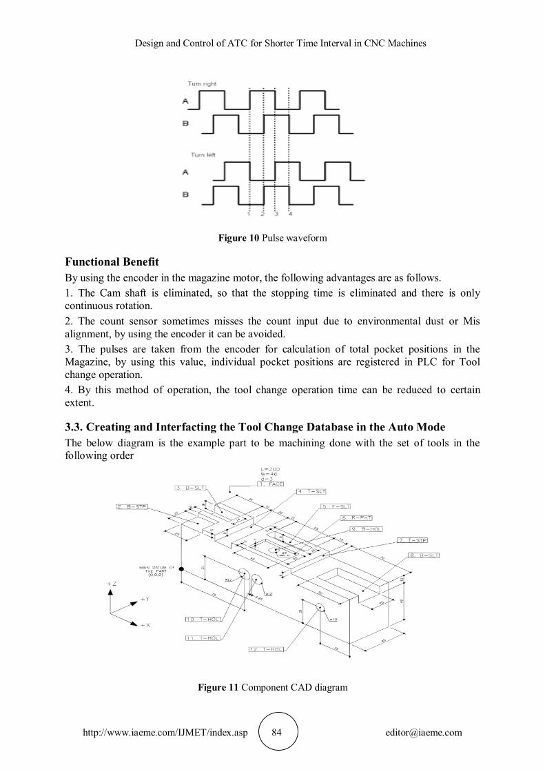
Figure 10 Pulse waveform
Functional Benefit By using the encoder in the magazine motor, the following advantages are as follows. 1. The Cam shaft is eliminated, so that the stopping time is eliminated and there is only continuous rotation. 2. The count sensor sometimes misses the count input due to environmental dust or Mis alignment, by using the encoder it can be avoided. 3. The pulses are taken from the encoder for calculation of total pocket positions in the Magazine, by using this value, individual pocket positions are registered in PLC for Tool change operation. 4. By this method of operation, the tool change operation time can be reduced to certain extent.
3.3. Creating and Interfacting the Tool Change Database in the Auto Mode The below diagram is the example part to be machining done with the set of tools in the following order
Figure 11 Component CAD diagram

M. Karthick, M. Sundarraj and T. Raja
http://www.iaeme.com/IJMET/index.asp 85 [email protected]
Operation sequence
Operation Tool Number
O1 FACE MILLING
T5
O2 STEP MILLING
T3
O3 SLOT MILLING
T10
O4 SLOT MILLING
T9
O5 SLOT MILLING
T7
O6 SLOT MILLING
T1
O7 STEP MILLING T12
O8 POCKET MILLING
T13
O9 CENTRE T8
DRILLING O10 TWIST
DRILLING T14
The below table is the order of tool change for machining the example part.
Figure 12 Tool positions on the ATC for the example part

Design and Control of ATC for Shorter Time Interval in CNC Machines
http://www.iaeme.com/IJMET/index.asp 86 [email protected]
4. SEQUENCE CYCLE OF ATC PROCESS The main component modules of which the ATC systems consist of are:
Tool magazine;
Tool transfer mechanism;
Parking station;
ATC arm;
Tool clamp mechanism (spindle). The automatic tool changer system’s role is to provide the machining center spindle with
the tool to follow the machining process and to bring the tool which exits the machining process in the tool magazine. Considering that the tools axes from the magazine are normal to the spindle axis, for changing the tool to exit the machining process with a new one, the ATC performs the following movements. Pos. 1 – ATC arm slides to the tool in the magazine (clamps the tool); Pos. 2 – ATC arm slides outward (extracts the tool from the magazine); Pos. 3 – ATC arm slides with the new tool into an Intermediary position; Pos. 4 – ATC arm slides inward with the new Tool Pos. 5 – ATC arm is rotated with 90º Bringing the new tool in changing position (tool axis is parallel to spindle axis); Pos. 6 – ATC arm slides to tool in spindle (Clamps the tool); Pos. 7 – ATC arm slides outward (extracts the tool from spindle); Pos. 8 – ATC arm rotates with 180º (the tool exchange Takes place); Pos. 9 – ATC arm slides inward (new tool is Clamped by spindle).
Figure 13 Tool change sequence
The sequential tool change cycle consists of all the movements performed by the ATC mechanism in order to transfer and change a new tool from the magazine with the tool in the spindle. The total time needed to exchange the tool from the spindle or the tool from the magazine is
◌ ݐݐ (1) ◌◌ + ݐ◌ + ◌◌ =

M. Karthick, M. Sundarraj and T. Raja
http://www.iaeme.com/IJMET/index.asp 87 [email protected]
Where: ◌◌ – the indexing time of the tool magazine; the necessary time for bringing the new Tool by the ATC mechanism into the waiting – ݐ◌ Position; ◌◌ – the necessary time to exchange the tool Taken from the tool magazine with the one in the spindle.
The time needed to bring the new tool from the tool magazine in the waiting position by the automatic tool changer arm is given in
(2) 5◌ + 4◌ + 3◌ + 2◌ + 1◌ = ݐ◌
Where: ◌1, ◌2, ◌3, ◌4, ◌5- are the necessary times For ATC to perform all the movements Associated to positions P1, P2, P3, P4, P5; because these movements are performed during the machining process, thus the time needed to bring the tool into the waiting Position ( ◌ݐ ) doesn’t influence the Machining process.This means the Machining process being stopped only for the actual tool exchange in spindle
◌◌ = ◌6 + ◌7 + ◌8 + ◌9 Where: ◌6, ◌7, ◌8, ◌9- are the necessary times for ATC to perform all the movements to
Perform the tool exchange in the spindle associated to positions P6, P7, P8, P9; because the auxiliary movements are overlapped with the machining process, the total time for exchanging the tool in the spindle is highly minimized.
4.1. Functional Benefits In the existing system in CNC machines, the tool change will run only after the completion of
the particular machining process .This will take 4 seconds to 8 seconds.
The aim of this method is, the next tool will be ready for tool change near the double arm during the machining process, so once the machining is completed only the double arm rotation is indexed to change the tool from Magazine to Spindle.
A set of tool change database is created for machining the particular component and it is being interfaced in the software to execute only during the AUTO mode.
It works normally when changed from AUTO to JOG mode.
By this method, the tool change operation is drastically reduced from normal time of 8 sec to 2 sec.
Only the double arm rotation indexing time is taken in to account.
Additionally the implementation of tool database interface in the existing software and the alteration in the PLC logics is to be performed.

Design and Control of ATC for Shorter Time Interval in CNC Machines
http://www.iaeme.com/IJMET/index.asp 88 [email protected]
5. CONCLUSION The different methods are used in this method to reduce the tool change operation time in CNC machines. Each method has its own advantage and disadvantage in terms of cost factor. Further in future, the selection of existing CNC machines to implement any one of the methods to reduce the cycle time without disturbing the external parameters at the reasonable cost.
REFERENCES [1] Robotic engineering an integrated approach by Richard D.Klafter, Thomas
A.Chmielewski, MichaelNegin.
[2] Introduction to Mechatronics and Measurement Systems by David G Alciatore, Michael B Histland Mechatronics by HMT.
[3] Automation, Production Systems and Computer-Integrated Manufacturing by Mikell P.Groover.
[4] Principles of Computer-Integrated Manufacturing by S.Kant Vajpayee.
[5] Allocating optimal index position on Tool magazines using genetic algorithms by Turkay Dereli, I.Huseyin Filiz.
[6] C.J. Chen, C.S. Tseng, The path and Location planning of workpieces by genetic algorithms, Journal of Intelligent Manufacturing 7 (1996) 69–76.
[7] Design of ATC for machining centers, OBREA, C[laudiu] F[lorin]; PASCU, M[arius]; MIHAILA, L[ucian] & FUNARU, M[arian]
[8] Constantin, G., Ghionea, A. & Zapciu, M., (2007). Structural Configuration Methods for Machine Tools,7ݐℎ International.
[9] Multidisciplinary conference, May 17-18, 2007, Romania, ISSN:1224-3264, pp. 107-114,
[10] Baia Mare Cong, M., Jing, L.& Quanpu L., (2008). A Novel Dual-Cam Linkage Drive Automatic Tool Changer for Horizontal Machining Center, Proceedings of the First International Conference on Intelligent Robotics and Applications: Part II, ICIRA 08, 2008,
[11] Springer-Verlag Berlin, Heidelberg, ISBN: 978-3-540-88516-0, Xiong, C. et al. (Eds.), pp. 368-377, Berlin.
[12] Gokler, M.I., Koc, M.B., (1997). “Design of an automatic tool changer With disc magazine for a CNC Horizontal machining center”, International Journal of Machine Tools and Manufacture, Vol. 37, No. 3, 1997, pp. 277-286
[13] Ajay Kumar, Simranjeet Singh, Sahil Barry, Shivam Bhardwaj, Er. Ajay Sharma and Er. Harpreet Singh. Parameter Optimization in Vertical Machining Center CNC for EN45 (Steel Alloy) Using Response Surface Methodology. International Journal of Mechanical Engineering and Technology, 7(2), 2016, pp. 288–299
[14] Mufaddal A. Saifee and Dr. Usha S. Mehta. Design and Implementation of FPGA Based G Code Compatible CNC Lathe Controller. International Journal of Electronics and Communication Engineering & Technology, 7 (1), 2016, pp. 75-86.