design and construction of structural systems
TRANSCRIPT

NIST NCSTAR 1-1A
Federal Building and Fire Safety Investigation of the World Trade Center Disaster
Design and Construction of Structural Systems
David A. Fanella Arnaldo T. Derecho S. K. Ghosh


NIST NCSTAR 1-1A
Federal Building and Fire Safety Investigation of the World Trade Center Disaster
Design and Construction of Structural Systems
David A. Fanella Arnaldo T. Derecho S. K. Ghosh S. K. Ghosh Associates, Inc. September 2005
U.S. Department of Commerce Carlos M. Gutierrez, Secretary Technology Administration Michelle O’Neill, Acting Under Secretary for Technology National Institute of Standards and Technology William Jeffrey, Director

Disclaimer No. 1
Certain commercial entities, equipment, products, or materials are identified in this document in order to describe a procedure or concept adequately or to trace the history of the procedures and practices used. Such identification is not intended to imply recommendation, endorsement, or implication that the entities, products, materials, or equipment are necessarily the best available for the purpose. Nor does such identification imply a finding of fault or negligence by the National Institute of Standards and Technology.
Disclaimer No. 2
The policy of NIST is to use the International System of Units (metric units) in all publications. In this document, however, units are presented in metric units or the inch-pound system, whichever is prevalent in the discipline.
Disclaimer No. 3
Pursuant to section 7 of the National Construction Safety Team Act, the NIST Director has determined that certain evidence received by NIST in the course of this Investigation is “voluntarily provided safety-related information” that is “not directly related to the building failure being investigated” and that “disclosure of that information would inhibit the voluntary provision of that type of information” (15 USC 7306c).
In addition, a substantial portion of the evidence collected by NIST in the course of the Investigation has been provided to NIST under nondisclosure agreements.
Disclaimer No. 4
NIST takes no position as to whether the design or construction of a WTC building was compliant with any code since, due to the destruction of the WTC buildings, NIST could not verify the actual (or as-built) construction, the properties and condition of the materials used, or changes to the original construction made over the life of the buildings. In addition, NIST could not verify the interpretations of codes used by applicable authorities in determining compliance when implementing building codes. Where an Investigation report states whether a system was designed or installed as required by a code provision, NIST has documentary or anecdotal evidence indicating whether the requirement was met, or NIST has independently conducted tests or analyses indicating whether the requirement was met.
Use in Legal Proceedings
No part of any report resulting from a NIST investigation into a structural failure or from an investigation under the National Construction Safety Team Act may be used in any suit or action for damages arising out of any matter mentioned in such report (15 USC 281a; as amended by P.L. 107-231).
National Institute of Standards and Technology National Construction Safety Team Act Report 1-1A Natl. Inst. Stand. Technol. Natl. Constr. Sfty. Tm. Act Rpt. 1-1A, 166 pages (September 2005) CODEN: NSPUE2
U.S. GOVERNMENT PRINTING OFFICE WASHINGTON: 2005 _________________________________________ For sale by the Superintendent of Documents, U.S. Government Printing Office Internet: bookstore.gpo.gov — Phone: (202) 512-1800 — Fax: (202) 512-2250 Mail: Stop SSOP, Washington, DC 20402-0001

NIST NCSTAR 1-1A, WTC Investigation iii
ABSTRACT
This report describes the provisions that were used to design and construct World Trade Center 1, 2, and 7. Included is a summary of the major provisions in the codes and standards together with the loads and load combinations that were used to design the buildings. Methods used to proportion structural members and other components of the buildings are also discussed, as well as tests that were performed to support the design. It is shown that the loads that were used to design the members were at least equal to those prescribed in the applicable codes and standards, and that the methods used to proportion the structural members followed the requirements in the applicable material design standards available at that time.
Also included in this report are the innovative systems, technologies, and materials that were used in the buildings, and the Port Authority’s acceptance procedures for such items. Fabrication and inspection requirements at the fabrication yard and inspection protocol during construction are discussed. Also covered are the details of the deviations to contract documents that were granted by the Port Authority, including the justifications for those deviations.
The information contained in this report is based on documents and structural drawings that were acquired from the following locations: (1) the offices of the Port Authority of New York and New Jersey in Newark, New Jersey, and New York City and (2) the National Institute of Standards and Technology in Gaithersburg, Maryland. Paper, microfilm, and electronic versions of these documents were obtained from these locations. Appendixes to this report include copies of referenced documents.
Keywords: Analysis, codes, construction, design, fabrication, innovative systems, inspection, loads, load combinations, materials, standards, tests, deviations, World Trade Center.

Abstract
iv NIST NCSTAR 1-1A, WTC Investigation
This page intentionally left blank.

NIST NCSTAR 1-1A, WTC Investigation v
TABLE OF CONTENTS
Abstract ........................................................................................................................................................ iii List of Figures .............................................................................................................................................. ix List of Tables ............................................................................................................................................... xi List of Acronyms and Abbreviations .........................................................................................................xiii Preface ........................................................................................................................................................ xv Executive Summary .................................................................................................................................. xxv
Chapter 1 Introduction ................................................................................................................................. 1
Chapter 2 Provisions Used to Design and Construct the Buildings ....................................................... 3
2.1 Building Codes Used in Design....................................................................................................... 3 2.1.1 WTC 1 and WTC 2 .............................................................................................................. 3 2.1.2 WTC 7 .................................................................................................................................. 3
2.2 Summary of Code Provisions .......................................................................................................... 4 2.2.1 Loads .................................................................................................................................... 4 2.2.2 Structural Design Requirements of the Code ..................................................................... 30
2.3 Summary of Methods Used to Proportion Structural Members and Components......................... 33 2.3.1 Overview ............................................................................................................................ 33 2.3.2 Exterior Columns ............................................................................................................... 34 2.3.3 Floor Trusses ...................................................................................................................... 37 2.3.4 Composite Steel Beams...................................................................................................... 46 2.3.5 Connections ........................................................................................................................ 49 2.3.6 Concrete Floor Slabs .......................................................................................................... 51 2.3.7 Steel Deck........................................................................................................................... 54 2.3.8 Hat Trusses ......................................................................................................................... 54
2.4 References...................................................................................................................................... 58
Chapter 3 Tests Performed to Support Design Innovations .................................................................. 61
3.1 Exterior Wall Panel Tests .............................................................................................................. 61 3.2 Wind Tunnel Tests......................................................................................................................... 65
3.2.1 Meteorological Program..................................................................................................... 65
Table of Contents
vi NIST NCSTAR 1-1A, WTC Investigation
3.2.2 Wind Tunnel Program ........................................................................................................ 68 3.3 Damping Unit Tests ....................................................................................................................... 76 3.4 Floor Truss Tests ........................................................................................................................... 78
3.4.1 Full-Scale Flexural Tests.................................................................................................... 78 3.4.2 Shear Knuckle Tests ........................................................................................................... 80 3.4.3 Interior Panel Connection Tests ......................................................................................... 82 3.4.4 Bearing Capacity Tests....................................................................................................... 85
3.5 Stud Shear Connector Tests ........................................................................................................... 88 3.6 References...................................................................................................................................... 88
Chapter 4 Port Authority Policies and Agreements with New York City Department of Buildings.................................................................................................................................... 91
Chapter 5 Innovative Systems, Technologies and Materials, and Acceptance Procedures Used by the Port Authority ................................................................................................................ 93
5.1 Innovative Features of the Structural System ................................................................................ 93 5.2 Lateral-Force-Resisting System of WTC 1 and WTC 2 ................................................................ 94 5.3 Damping Units ............................................................................................................................... 97
5.3.1 Overview ............................................................................................................................ 97 5.3.2 Specifications ................................................................................................................... 100
5.4 Floor Trusses................................................................................................................................ 105 5.4.1 Overview .......................................................................................................................... 105 5.4.2 Specifications ................................................................................................................... 108
5.5 References.................................................................................................................................... 111
Chapter 6 Fabrication and Inspection Requirements at the Fabrication Yard ................................... 113
6.1 Overview...................................................................................................................................... 113 6.2 Summary of Code Requirements for Fabrication and Inspection................................................ 113
6.2.1 Fabrication Requirements................................................................................................. 114 6.2.2 Inspection Requirements .................................................................................................. 114
6.3 Summary of Fabrication and Inspection Requirements at the Fabrication Yard for WTC 1 and WTC 2................................................................................................................................... 114 6.3.1 Floor Trusses .................................................................................................................... 115 6.3.2 Box Core Columns and Built-up Beams .......................................................................... 115 6.3.3 Exterior Wall from Elevation 363 ft to the 9th Floor Splice ............................................ 117

Table of Contents
NIST NCSTAR 1-1A, WTC Investigation vii
6.3.4 Exterior Wall Above 9th Floor Splice.............................................................................. 118 6.3.5 Rolled Columns and Beams ............................................................................................. 118 6.3.6 Other Requirements.......................................................................................................... 119
6.4 Summary of Fabrication and Inspection Requirements at the Fabrication Yard for WTC 7....... 119 6.4.1 Fabrication........................................................................................................................ 120 6.4.2 Inspection ......................................................................................................................... 121
6.5 References.................................................................................................................................... 121
Chapter 7 Inspection Protocol During Construction ............................................................................ 123
7.1 Overview...................................................................................................................................... 123 7.2 Erection Marks and Marking System........................................................................................... 123 7.3 Quality Control and Inspection Program ..................................................................................... 123 7.4 Reference ..................................................................................................................................... 124
Chapter 8 Deviations Granted by the Port Authority ............................................................................ 125
8.1 Overview...................................................................................................................................... 125 8.2 Deviations Relating to Fabrication/Erection Tolerances ............................................................. 125 8.3 Deviations Relating to Defective Components ............................................................................ 127 8.4 Deviations Relating to Alternate Fabrication/Erection Procedures ............................................. 129 8.5 Deviations Relating to Product Substitutions .............................................................................. 129 8.6 Deviations Relating to Inspection Practice .................................................................................. 130 8.7 Reference ..................................................................................................................................... 130
Appendix A Supporting Documents for Chapter 2................................................................................... 131
Appendix B Supporting Documents for Chapter 3................................................................................... 137
Appendix C Supporting Documents for Chapter 4................................................................................... 215
Appendix D Supporting Documents for Chapter 5................................................................................... 225
Appendix E Supporting Document for Chapter 6..................................................................................... 275

Table of Contents
viii NIST NCSTAR 1-1A, WTC Investigation
Appendix F Supporting Documents for Chapter 7................................................................................... 389
Appendix G Supporting Documents for Chapter 8................................................................................... 405

NIST NCSTAR 1-1A, WTC Investigation ix
LIST OF FIGURES
Figure P–1. The eight projects in the federal building and fire safety investigation of the WTC disaster ...............................................................................................................................xvii
Figure 2–1. Definitions used in design criteria for WTC 1 and WTC 2. .................................................. 5 Figure 2–2. Core area in a representative floor plan of WTC 1 and WTC 2............................................. 6 Figure 2–3. Design criteria for WTC 1 and WTC 2: floor inside of core – unit dead load....................... 7 Figure 2–4. Design criteria for WTC 1 and WTC 2: floor outside of core – unit dead load................... 11 Figure 2–5. Design load criteria for WTC 7............................................................................................ 13 Figure 2–6. Design criteria for WTC 1 and WTC 2: floor inside of core – live load. ............................ 14 Figure 2–7. Design criteria for WTC 1 and WTC 2: typical floor slabs outside of core – live load....... 19 Figure 2–8. Design criteria for WTC 1 and WTC 2: columns outside of core – live load...................... 20 Figure 2–9. Design criteria for WTC 1 and WTC 2 – live load reduction. ............................................. 22 Figure 2–10. Design criteria for WTC 1 and WTC 2: floors inside of core, except for tenant areas –
live load reduction................................................................................................................ 23 Figure 2–11. Design criteria for WTC 1 and WTC 2: floors inside of core, tenant areas – live load
reduction. ............................................................................................................................. 24 Figure 2–12. Design criteria for WTC 1 and WTC 2: floors outside of core............................................ 25 Figure 2–13. Design criteria for WTC 1 and WTC 2: floors outside of core – live load reduction. ......... 26 Figure 2–14. Design criteria for WTC 1 and WTC 2: columns outside of core – live load
reduction. ............................................................................................................................. 27 Figure 2–15. Total deflections (ft) at top of WTC 1 and WTC 2 due to wind. ......................................... 36 Figure 2–16. Design method for exterior columns in WTC 1 and WTC 2. .............................................. 38 Figure 2–17. Design method for floor trusses in WTC 1 and WTC 2. ..................................................... 40 Figure 2–18. Tabulation of component capacities of floor truss connections in WTC 1 and WTC 2. ..... 44 Figure 2–19. Design standard for composite sections in WTC 1 and WTC 2. ......................................... 46 Figure 2–20. Design standard for bolted connections in WTC 1 and WTC 2........................................... 49 Figure 2–21. Schedule of welding electrodes for connections in exterior columns in WTC 1 and
WTC 2.................................................................................................................................. 50 Figure 2–22. General notes for structural concrete in WTC 1 and WTC 2............................................... 51 Figure 2–23. Design assumptions for concrete floor slabs in WTC 1 and WTC 2. .................................. 52 Figure 2–24. Reinforced concrete one-way slab design in WTC 1 and WTC 2. ...................................... 53 Figure 2–25. Specification for reinforcing steel used in WTC 1 and WTC 2. .......................................... 54 Figure 2–26. Design criteria for steel deck in WTC 1 and WTC 2. .......................................................... 55 Figure 2–27. Design method for hat trusses in WTC 1 and WTC 2. ........................................................ 56

List of Figures
x NIST NCSTAR 1-1A, WTC Investigation
Figure 3–1. Subassembly used for testing external wall panel in WTC 1 and WTC 2. .......................... 61 Figure 3–2. Loads applied to model of exterior wall panel..................................................................... 62 Figure 3–3. Test rig used for testing model of external wall panels in WTC 1 and WTC 2. .................. 63 Figure 3–4. Spandrel flanges used in some test models of exterior wall panels. .................................... 63 Figure 3–5. Displacements and rotations measured during model test program of exterior wall
panels. .................................................................................................................................. 64 Figure 3–6. Location of anemometers in wind study for WTC 1 and WTC 2. ....................................... 69 Figure 3–7. Wind directions that produced the greatest displacements at the top of the tower
during the wind tunnel tests. ................................................................................................ 72 Figure 3–8. Definition of grid system and tower configurations for wind tunnel tests at CSU. ............. 73 Figure 3–9. Comparison of the variation of the N-S deflection (amplitude) of WTC 1 subjected to
E-W wind for different degrees of damping (γ) and flow conditions. ................................. 75 Figure 3–10. Location of concentrated loads in the full-scale testing of the floor trusses in WTC 1
and WTC 2........................................................................................................................... 79 Figure 3–11. Results from full-scale flexural tests of 32 in. deep floor trusses. ....................................... 79 Figure 3–12. Maximum midspan deflections from full-scale flexural tests of 32 in. deep floor
trusses................................................................................................................................... 80 Figure 3–13. Test setup for longitudinal shear knuckle tests. ................................................................... 81 Figure 3–14. Results from longitudinal shear knuckle tests...................................................................... 82 Figure 3–15. Test setup for interior panel connection test – horizontal load on welds. ............................ 83 Figure 3–16. Results from interior panel connection tests – horizontal load on welds............................. 84 Figure 3–17. Test setup for interior panel connection test – vertical load on welds. ................................ 84 Figure 3–18. Test setup for first set of bearing capacity tests on floor trusses.......................................... 85 Figure 3–19. Results from the first set of bearing capacity tests on floor trusses. .................................... 86 Figure 3–20. Test setup for second set of bearing capacity tests on floor trusses. .................................... 87 Figure 3–21. Results from the second set of bearing capacity tests on floor trusses. ............................... 87
Figure 5–1. Exterior wall panels in WTC 1 and WTC 2......................................................................... 94 Figure 5–2. Exterior wall panel transition in WTC 1 and WTC 2. ......................................................... 95 Figure 5–3. Representative structural framing plan on a typical floor of WTC 1 or WTC 2.................. 96 Figure 5–4. Floor truss member with Type A damping units. ................................................................ 98 Figure 5–5. Wide-flange beam floor member with Type B damping units. ........................................... 99 Figure 5–6. Damping unit details – Types A and B. ............................................................................. 100 Figure 5–7. Parameters related to mechanical properties of damping units.......................................... 101 Figure 5–8. Prefabricated floor unit used in WTC 1 and WTC 2. ........................................................ 106 Figure 5–9. Section through the main double trusses in the floor system of WTC 1 and WTC 2. ....... 107

NIST NCSTAR 1-1A, WTC Investigation xi
LIST OF TABLES
Table P–1. Federal building and fire safety investigation of the WTC disaster.................................... xvi Table P–2. Public meetings and briefings of the WTC Investigation. .................................................. xix
Table 2–1. Percentage of live load per the 1968 Code........................................................................... 21 Table 2–2. Design wind pressures on vertical surfaces per the 1968 Code (Table RS 9-5-1)............... 28 Table 2–3. Design wind pressures on horizontal and inclined surfaces per the 1968
Code (Table RS 9-5-2)......................................................................................................... 28 Table 2–4. Equivalent design wind velocity for WTC 1 and WTC 2.a.................................................. 34
Table 3–1. Constants used in wind study of WTC 1 and WTC 2. ......................................................... 67 Table 3–2. Wind directions that produced the largest displacements at the tops of the towers
from the twin-tower wind tunnel tests. ................................................................................ 74
Table 5–1. Material specifications for damping units per WTC Contract WTC-224.0.a..................... 103 Table 5–2. Acceptance requirements for damping units per WTC Contract WTC-224.0. .................. 104 Table 5–3. Five-year acceptance requirements for damping units per WTC Contract WTC-224.0.... 105

List of Tables
xii NIST NCSTAR 1-1A, WTC Investigation
This page intentionally left blank.
NIST NCSTAR 1-1A, WTC Investigation xiii
LIST OF ACRONYMS AND ABBREVIATIONS
Acronyms
3M Minnesota Mining and Manufacturing Company
ACI American Concrete Institute
AISC American Institute of Steel Construction
ASTM ASTM International
AWS American Welding Society
CSU Colorado State University
JFK John F. Kennedy (Airport)
KKE Karl Koch Erecting Company
LERA Leslie E. Robertson Associates
NIST National Institute of Standards and Technology
NPL National Physical Laboratory
PANYNJ Port Authority of New York and New Jersey
PDM Pittsburgh-Des Moines Steel Company
PONYA Port of New York Authority
PPG Pittsburgh Plate Glass
SHCR Skilling, Helle, Christiansen, & Robertson
TRCC Tishman Realty & Construction Company
WSHJ Worthington, Skilling, Helle, & Jackson
WTC World Trade Center
WTC 1 World Trade Center 1 (North Tower)
WTC 2 World Trade Center 2 (South Tower)
WTC 7 World Trade Center 7
Abbreviations
°F degrees Fahrenheit
cps cycles per second
ft foot
ft2 square foot
List of Acronyms and Abbreviations
xiv NIST NCSTAR 1-1A, WTC Investigation
ft3 cubic foot
in. inch
kip a force equal to 1,000 pounds
ksi 1,000 pounds per square inch
lb pound
m meter
m/s meters per second
min minute
mph miles per hour
pcf pounds per cubic foot
plf pounds per linear foot
psf pounds per square foot
psi pounds per square inch
s second

NIST NCSTAR 1-1A, WTC Investigation xv
PREFACE
Genesis of This Investigation
Immediately following the terrorist attack on the World Trade Center (WTC) on September 11, 2001, the Federal Emergency Management Agency (FEMA) and the American Society of Civil Engineers began planning a building performance study of the disaster. The week of October 7, as soon as the rescue and search efforts ceased, the Building Performance Study Team went to the site and began its assessment. This was to be a brief effort, as the study team consisted of experts who largely volunteered their time away from their other professional commitments. The Building Performance Study Team issued its report in May 2002, fulfilling its goal “to determine probable failure mechanisms and to identify areas of future investigation that could lead to practical measures for improving the damage resistance of buildings against such unforeseen events.”
On August 21, 2002, with funding from the U.S. Congress through FEMA, the National Institute of Standards and Technology (NIST) announced its building and fire safety investigation of the WTC disaster. On October 1, 2002, the National Construction Safety Team Act (Public Law 107-231), was signed into law. The NIST WTC Investigation was conducted under the authority of the National Construction Safety Team Act.
The goals of the investigation of the WTC disaster were:
• To investigate the building construction, the materials used, and the technical conditions that contributed to the outcome of the WTC disaster.
• To serve as the basis for:
− Improvements in the way buildings are designed, constructed, maintained, and used;
− Improved tools and guidance for industry and safety officials;
− Recommended revisions to current codes, standards, and practices; and
− Improved public safety.
The specific objectives were:
1. Determine why and how WTC 1 and WTC 2 collapsed following the initial impacts of the aircraft and why and how WTC 7 collapsed;
2. Determine why the injuries and fatalities were so high or low depending on location, including all technical aspects of fire protection, occupant behavior, evacuation, and emergency response;
3. Determine what procedures and practices were used in the design, construction, operation, and maintenance of WTC 1, 2, and 7; and
4. Identify, as specifically as possible, areas in current building and fire codes, standards, and practices that warrant revision.

Preface
xvi NIST NCSTAR 1-1A, WTC Investigation
NIST is a nonregulatory agency of the U.S. Department of Commerce’s Technology Administration. The purpose of NIST investigations is to improve the safety and structural integrity of buildings in the United States, and the focus is on fact finding. NIST investigative teams are authorized to assess building performance and emergency response and evacuation procedures in the wake of any building failure that has resulted in substantial loss of life or that posed significant potential of substantial loss of life. NIST does not have the statutory authority to make findings of fault nor negligence by individuals or organizations. Further, no part of any report resulting from a NIST investigation into a building failure or from an investigation under the National Construction Safety Team Act may be used in any suit or action for damages arising out of any matter mentioned in such report (15 USC 281a, as amended by Public Law 107-231).
Organization of the Investigation
The National Construction Safety Team for this Investigation, appointed by the then NIST Director, Dr. Arden L. Bement, Jr., was led by Dr. S. Shyam Sunder. Dr. William L. Grosshandler served as Associate Lead Investigator, Mr. Stephen A. Cauffman served as Program Manager for Administration, and Mr. Harold E. Nelson served on the team as a private sector expert. The Investigation included eight interdependent projects whose leaders comprised the remainder of the team. A detailed description of each of these eight projects is available at http://wtc.nist.gov. The purpose of each project is summarized in Table P–1, and the key interdependencies among the projects are illustrated in Fig. P–1.
Table P–1. Federal building and fire safety investigation of the WTC disaster. Technical Area and Project Leader Project Purpose
Analysis of Building and Fire Codes and Practices; Project Leaders: Dr. H. S. Lew and Mr. Richard W. Bukowski
Document and analyze the code provisions, procedures, and practices used in the design, construction, operation, and maintenance of the structural, passive fire protection, and emergency access and evacuation systems of WTC 1, 2, and 7.
Baseline Structural Performance and Aircraft Impact Damage Analysis; Project Leader: Dr. Fahim H. Sadek
Analyze the baseline performance of WTC 1 and WTC 2 under design, service, and abnormal loads, and aircraft impact damage on the structural, fire protection, and egress systems.
Mechanical and Metallurgical Analysis of Structural Steel; Project Leader: Dr. Frank W. Gayle
Determine and analyze the mechanical and metallurgical properties and quality of steel, weldments, and connections from steel recovered from WTC 1, 2, and 7.
Investigation of Active Fire Protection Systems; Project Leader: Dr. David D. Evans; Dr. William Grosshandler
Investigate the performance of the active fire protection systems in WTC 1, 2, and 7 and their role in fire control, emergency response, and fate of occupants and responders.
Reconstruction of Thermal and Tenability Environment; Project Leader: Dr. Richard G. Gann
Reconstruct the time-evolving temperature, thermal environment, and smoke movement in WTC 1, 2, and 7 for use in evaluating the structural performance of the buildings and behavior and fate of occupants and responders.
Structural Fire Response and Collapse Analysis; Project Leaders: Dr. John L. Gross and Dr. Therese P. McAllister
Analyze the response of the WTC towers to fires with and without aircraft damage, the response of WTC 7 in fires, the performance of composite steel-trussed floor systems, and determine the most probable structural collapse sequence for WTC 1, 2, and 7.
Occupant Behavior, Egress, and Emergency Communications; Project Leader: Mr. Jason D. Averill
Analyze the behavior and fate of occupants and responders, both those who survived and those who did not, and the performance of the evacuation system.
Emergency Response Technologies and Guidelines; Project Leader: Mr. J. Randall Lawson
Document the activities of the emergency responders from the time of the terrorist attacks on WTC 1 and WTC 2 until the collapse of WTC 7, including practices followed and technologies used.

Preface
NIST NCSTAR 1-1A, WTC Investigation xvii
NIST WTC Investigation ProjectsNIST WTC Investigation Projects
Analysis of Steel
Structural Collapse
Evacuation
Baseline Performance
& Impact Damage
Analysis of Codes and Practices
Emergency Response
Active Fire Protection
Thermal and Tenability
Environment
Video/Photographic Records
Oral History Data
Emergency Response Records
Recovered Structural Steel
WTC Building Performance StudyRecommendations
Government, Industry, Professional, Academic Inputs
Public Inputs
Figure P–1. The eight projects in the federal building and fire safety
investigation of the WTC disaster.
National Construction Safety Team Advisory Committee
The NIST Director also established an advisory committee as mandated under the National Construction Safety Team Act. The initial members of the committee were appointed following a public solicitation. These were:
• Paul Fitzgerald, Executive Vice President (retired) FM Global, National Construction Safety Team Advisory Committee Chair
• John Barsom, President, Barsom Consulting, Ltd.
• John Bryan, Professor Emeritus, University of Maryland
• David Collins, President, The Preview Group, Inc.
• Glenn Corbett, Professor, John Jay College of Criminal Justice
• Philip DiNenno, President, Hughes Associates, Inc.

Preface
xviii NIST NCSTAR 1-1A, WTC Investigation
• Robert Hanson, Professor Emeritus, University of Michigan
• Charles Thornton, Co-Chairman and Managing Principal, The Thornton-Tomasetti Group, Inc.
• Kathleen Tierney, Director, Natural Hazards Research and Applications Information Center, University of Colorado at Boulder
• Forman Williams, Director, Center for Energy Research, University of California at San Diego
This National Construction Safety Team Advisory Committee provided technical advice during the Investigation and commentary on drafts of the Investigation reports prior to their public release. NIST has benefited from the work of many people in the preparation of these reports, including the National Construction Safety Team Advisory Committee. The content of the reports and recommendations, however, are solely the responsibility of NIST.
Public Outreach
During the course of this Investigation, NIST held public briefings and meetings (listed in Table P–2) to solicit input from the public, present preliminary findings, and obtain comments on the direction and progress of the Investigation from the public and the Advisory Committee.
NIST maintained a publicly accessible Web site during this Investigation at http://wtc.nist.gov. The site contained extensive information on the background and progress of the Investigation.
NIST’s WTC Public-Private Response Plan
The collapse of the WTC buildings has led to broad reexamination of how tall buildings are designed, constructed, maintained, and used, especially with regard to major events such as fires, natural disasters, and terrorist attacks. Reflecting the enhanced interest in effecting necessary change, NIST, with support from Congress and the Administration, has put in place a program, the goal of which is to develop and implement the standards, technology, and practices needed for cost-effective improvements to the safety and security of buildings and building occupants, including evacuation, emergency response procedures, and threat mitigation.
The strategy to meet this goal is a three-part NIST-led public-private response program that includes:
• A federal building and fire safety investigation to study the most probable factors that contributed to post-aircraft impact collapse of the WTC towers and the 47-story WTC 7 building, and the associated evacuation and emergency response experience.
• A research and development (R&D) program to (a) facilitate the implementation of recommendations resulting from the WTC Investigation, and (b) provide the technical basis for cost-effective improvements to national building and fire codes, standards, and practices that enhance the safety of buildings, their occupants, and emergency responders.

Preface
NIST NCSTAR 1-1A, WTC Investigation xix
Table P–2. Public meetings and briefings of the WTC Investigation. Date Location Principal Agenda
June 24, 2002 New York City, NY Public meeting: Public comments on the Draft Plan for the pending WTC Investigation.
August 21, 2002 Gaithersburg, MD Media briefing announcing the formal start of the Investigation. December 9, 2002 Washington, DC Media briefing on release of the Public Update and NIST request
for photographs and videos. April 8, 2003
New York City, NY Joint public forum with Columbia University on first-person interviews.
April 29–30, 2003 Gaithersburg, MD NCST Advisory Committee meeting on plan for and progress on WTC Investigation with a public comment session.
May 7, 2003 New York City, NY Media briefing on release of May 2003 Progress Report. August 26–27, 2003 Gaithersburg, MD NCST Advisory Committee meeting on status of the WTC
investigation with a public comment session. September 17, 2003 New York City, NY Media and public briefing on initiation of first-person data
collection projects. December 2–3, 2003 Gaithersburg, MD NCST Advisory Committee meeting on status and initial results
and release of the Public Update with a public comment session. February 12, 2004 New York City, NY Public meeting on progress and preliminary findings with public
comments on issues to be considered in formulating final recommendations.
June 18, 2004 New York City, NY Media/public briefing on release of June 2004 Progress Report. June 22–23, 2004 Gaithersburg, MD NCST Advisory Committee meeting on the status of and
preliminary findings from the WTC Investigation with a public comment session.
August 24, 2004 Northbrook, IL Public viewing of standard fire resistance test of WTC floor system at Underwriters Laboratories, Inc.
October 19–20, 2004 Gaithersburg, MD NCST Advisory Committee meeting on status and near complete set of preliminary findings with a public comment session.
November 22, 2004 Gaithersburg, MD NCST Advisory Committee discussion on draft annual report to Congress, a public comment session, and a closed session to discuss pre-draft recommendations for WTC Investigation.
April 5, 2005 New York City, NY Media and public briefing on release of the probable collapse sequence for the WTC towers and draft reports for the projects on codes and practices, evacuation, and emergency response.
June 23, 2005 New York City, NY Media and public briefing on release of all draft reports for the WTC towers and draft recommendations for public comment.
September 12–13, 2005
Gaithersburg, MD NCST Advisory Committee meeting on disposition of public comments and update to draft reports for the WTC towers.
September 13–15, 2005
Gaithersburg, MD WTC Technical Conference for stakeholders and technical community for dissemination of findings and recommendations and opportunity for public to make technical comments.
• A dissemination and technical assistance program (DTAP) to (a) engage leaders of the construction and building community in ensuring timely adoption and widespread use of proposed changes to practices, standards, and codes resulting from the WTC Investigation and the R&D program, and (b) provide practical guidance and tools to better prepare facility owners, contractors, architects, engineers, emergency responders, and regulatory authorities to respond to future disasters.
The desired outcomes are to make buildings, occupants, and first responders safer in future disaster events.

Preface
xx NIST NCSTAR 1-1A, WTC Investigation
National Construction Safety Team Reports on the WTC Investigation
A final report on the collapse of the WTC towers is being issued as NIST NCSTAR 1. A companion report on the collapse of WTC 7 is being issued as NIST NCSTAR 1A. The present report is one of a set that provides more detailed documentation of the Investigation findings and the means by which these technical results were achieved. As such, it is part of the archival record of this Investigation. The titles of the full set of Investigation publications are:
NIST (National Institute of Standards and Technology). 2005. Federal Building and Fire Safety Investigation of the World Trade Center Disaster: Final Report on the Collapse of the World Trade Center Towers. NIST NCSTAR 1. Gaithersburg, MD, September.
NIST (National Institute of Standards and Technology). 2008. Federal Building and Fire Safety Investigation of the World Trade Center Disaster: Final Report on the Collapse of World Trade Center 7. NIST NCSTAR 1A. Gaithersburg, MD, November.
Lew, H. S., R. W. Bukowski, and N. J. Carino. 2005. Federal Building and Fire Safety Investigation of the World Trade Center Disaster: Design, Construction, and Maintenance of Structural and Life Safety Systems. NIST NCSTAR 1-1. National Institute of Standards and Technology. Gaithersburg, MD, September.
Fanella, D. A., A. T. Derecho, and S. K. Ghosh. 2005. Federal Building and Fire Safety Investigation of the World Trade Center Disaster: Design and Construction of Structural Systems. NIST NCSTAR 1-1A. National Institute of Standards and Technology. Gaithersburg, MD, September.
Ghosh, S. K., and X. Liang. 2005. Federal Building and Fire Safety Investigation of the World Trade Center Disaster: Comparison of Building Code Structural Requirements. NIST NCSTAR 1-1B. National Institute of Standards and Technology. Gaithersburg, MD, September.
Fanella, D. A., A. T. Derecho, and S. K. Ghosh. 2005. Federal Building and Fire Safety Investigation of the World Trade Center Disaster: Maintenance and Modifications to Structural Systems. NIST NCSTAR 1-1C. National Institute of Standards and Technology. Gaithersburg, MD, September.
Grill, R. A., and D. A. Johnson. 2005. Federal Building and Fire Safety Investigation of the World Trade Center Disaster: Fire Protection and Life Safety Provisions Applied to the Design and Construction of World Trade Center 1, 2, and 7 and Post-Construction Provisions Applied after Occupancy. NIST NCSTAR 1-1D. National Institute of Standards and Technology. Gaithersburg, MD, September.
Razza, J. C., and R. A. Grill. 2005. Federal Building and Fire Safety Investigation of the World Trade Center Disaster: Comparison of Codes, Standards, and Practices in Use at the Time of the Design and Construction of World Trade Center 1, 2, and 7. NIST NCSTAR 1-1E. National Institute of Standards and Technology. Gaithersburg, MD, September.
Grill, R. A., D. A. Johnson, and D. A. Fanella. 2005. Federal Building and Fire Safety Investigation of the World Trade Center Disaster: Comparison of the 1968 and Current (2003) New

Preface
NIST NCSTAR 1-1A, WTC Investigation xxi
York City Building Code Provisions. NIST NCSTAR 1-1F. National Institute of Standards and Technology. Gaithersburg, MD, September.
Grill, R. A., and D. A. Johnson. 2005. Federal Building and Fire Safety Investigation of the World Trade Center Disaster: Amendments to the Fire Protection and Life Safety Provisions of the New York City Building Code by Local Laws Adopted While World Trade Center 1, 2, and 7 Were in Use. NIST NCSTAR 1-1G. National Institute of Standards and Technology. Gaithersburg, MD, September.
Grill, R. A., and D. A. Johnson. 2005. Federal Building and Fire Safety Investigation of the World Trade Center Disaster: Post-Construction Modifications to Fire Protection and Life Safety Systems of World Trade Center 1 and 2. NIST NCSTAR 1-1H. National Institute of Standards and Technology. Gaithersburg, MD, September.
Grill, R. A., D. A. Johnson, and D. A. Fanella. 2005. Federal Building and Fire Safety Investigation of the World Trade Center Disaster: Post-Construction Modifications to Fire Protection, Life Safety, and Structural Systems of World Trade Center 7. NIST NCSTAR 1-1I. National Institute of Standards and Technology. Gaithersburg, MD, September.
Grill, R. A., and D. A. Johnson. 2005. Federal Building and Fire Safety Investigation of the World Trade Center Disaster: Design, Installation, and Operation of Fuel System for Emergency Power in World Trade Center 7. NIST NCSTAR 1-1J. National Institute of Standards and Technology. Gaithersburg, MD, September.
Sadek, F. 2005. Federal Building and Fire Safety Investigation of the World Trade Center Disaster: Baseline Structural Performance and Aircraft Impact Damage Analysis of the World Trade Center Towers. NIST NCSTAR 1-2. National Institute of Standards and Technology. Gaithersburg, MD, September.
Faschan, W. J., and R. B. Garlock. 2005. Federal Building and Fire Safety Investigation of the World Trade Center Disaster: Reference Structural Models and Baseline Performance Analysis of the World Trade Center Towers. NIST NCSTAR 1-2A. National Institute of Standards and Technology. Gaithersburg, MD, September.
Kirkpatrick, S. W., R. T. Bocchieri, F. Sadek, R. A. MacNeill, S. Holmes, B. D. Peterson, R. W. Cilke, C. Navarro. 2005. Federal Building and Fire Safety Investigation of the World Trade Center Disaster: Analysis of Aircraft Impacts into the World Trade Center Towers, NIST NCSTAR 1-2B. National Institute of Standards and Technology. Gaithersburg, MD, September.
Gayle, F. W., R. J. Fields, W. E. Luecke, S. W. Banovic, T. Foecke, C. N. McCowan, T. A. Siewert, and J. D. McColskey. 2005. Federal Building and Fire Safety Investigation of the World Trade Center Disaster: Mechanical and Metallurgical Analysis of Structural Steel. NIST NCSTAR 1-3. National Institute of Standards and Technology. Gaithersburg, MD, September.
Luecke, W. E., T. A. Siewert, and F. W. Gayle. 2005. Federal Building and Fire Safety Investigation of the World Trade Center Disaster: Contemporaneous Structural Steel Specifications. NIST Special Publication 1-3A. National Institute of Standards and Technology. Gaithersburg, MD, September.

Preface
xxii NIST NCSTAR 1-1A, WTC Investigation
Banovic, S. W. 2005. Federal Building and Fire Safety Investigation of the World Trade Center Disaster: Steel Inventory and Identification. NIST NCSTAR 1-3B. National Institute of Standards and Technology. Gaithersburg, MD, September.
Banovic, S. W., and T. Foecke. 2005. Federal Building and Fire Safety Investigation of the World Trade Center Disaster: Damage and Failure Modes of Structural Steel Components. NIST NCSTAR 1-3C. National Institute of Standards and Technology. Gaithersburg, MD, September.
Luecke, W. E., J. D. McColskey, C. N. McCowan, S. W. Banovic, R. J. Fields, T. Foecke, T. A. Siewert, and F. W. Gayle. 2005. Federal Building and Fire Safety Investigation of the World Trade Center Disaster: Mechanical Properties of Structural Steels. NIST NCSTAR 1-3D. National Institute of Standards and Technology. Gaithersburg, MD, September.
Banovic, S. W., C. N. McCowan, and W. E. Luecke. 2005. Federal Building and Fire Safety Investigation of the World Trade Center Disaster: Physical Properties of Structural Steels. NIST NCSTAR 1-3E. National Institute of Standards and Technology. Gaithersburg, MD, September.
Evans, D. D., R. D. Peacock, E. D. Kuligowski, W. S. Dols, and W. L. Grosshandler. 2005. Federal Building and Fire Safety Investigation of the World Trade Center Disaster: Active Fire Protection Systems. NIST NCSTAR 1-4. National Institute of Standards and Technology. Gaithersburg, MD, September.
Kuligowski, E. D., D. D. Evans, and R. D. Peacock. 2005. Federal Building and Fire Safety Investigation of the World Trade Center Disaster: Post-Construction Fires Prior to September 11, 2001. NIST NCSTAR 1-4A. National Institute of Standards and Technology. Gaithersburg, MD, September.
Hopkins, M., J. Schoenrock, and E. Budnick. 2005. Federal Building and Fire Safety Investigation of the World Trade Center Disaster: Fire Suppression Systems. NIST NCSTAR 1-4B. National Institute of Standards and Technology. Gaithersburg, MD, September.
Keough, R. J., and R. A. Grill. 2005. Federal Building and Fire Safety Investigation of the World Trade Center Disaster: Fire Alarm Systems. NIST NCSTAR 1-4C. National Institute of Standards and Technology. Gaithersburg, MD, September.
Ferreira, M. J., and S. M. Strege. 2005. Federal Building and Fire Safety Investigation of the World Trade Center Disaster: Smoke Management Systems. NIST NCSTAR 1-4D. National Institute of Standards and Technology. Gaithersburg, MD, September.
Gann, R. G., A. Hamins, K. B. McGrattan, G. W. Mulholland, H. E. Nelson, T. J. Ohlemiller, W. M. Pitts, and K. R. Prasad. 2005. Federal Building and Fire Safety Investigation of the World Trade Center Disaster: Reconstruction of the Fires in the World Trade Center Towers. NIST NCSTAR 1-5. National Institute of Standards and Technology. Gaithersburg, MD, September.
Pitts, W. M., K. M. Butler, and V. Junker. 2005. Federal Building and Fire Safety Investigation of the World Trade Center Disaster: Visual Evidence, Damage Estimates, and Timeline Analysis. NIST NCSTAR 1-5A. National Institute of Standards and Technology. Gaithersburg, MD, September.

Preface
NIST NCSTAR 1-1A, WTC Investigation xxiii
Hamins, A., A. Maranghides, K. B. McGrattan, E. Johnsson, T. J. Ohlemiller, M. Donnelly, J. Yang, G. Mulholland, K. R. Prasad, S. Kukuck, R. Anleitner and T. McAllister. 2005. Federal Building and Fire Safety Investigation of the World Trade Center Disaster: Experiments and Modeling of Structural Steel Elements Exposed to Fire. NIST NCSTAR 1-5B. National Institute of Standards and Technology. Gaithersburg, MD, September.
Ohlemiller, T. J., G. W. Mulholland, A. Maranghides, J. J. Filliben, and R. G. Gann. 2005. Federal Building and Fire Safety Investigation of the World Trade Center Disaster: Fire Tests of Single Office Workstations. NIST NCSTAR 1-5C. National Institute of Standards and Technology. Gaithersburg, MD, September.
Gann, R. G., M. A. Riley, J. M. Repp, A. S. Whittaker, A. M. Reinhorn, and P. A. Hough. 2005. Federal Building and Fire Safety Investigation of the World Trade Center Disaster: Reaction of Ceiling Tile Systems to Shocks. NIST NCSTAR 1-5D. National Institute of Standards and Technology. Gaithersburg, MD, September.
Hamins, A., A. Maranghides, K. B. McGrattan, T. J. Ohlemiller, and R. Anleitner. 2005. Federal Building and Fire Safety Investigation of the World Trade Center Disaster: Experiments and Modeling of Multiple Workstations Burning in a Compartment. NIST NCSTAR 1-5E. National Institute of Standards and Technology. Gaithersburg, MD, September.
McGrattan, K. B., C. Bouldin, and G. Forney. 2005. Federal Building and Fire Safety Investigation of the World Trade Center Disaster: Computer Simulation of the Fires in the World Trade Center Towers. NIST NCSTAR 1-5F. National Institute of Standards and Technology. Gaithersburg, MD, September.
Prasad, K. R., and H. R. Baum. 2005. Federal Building and Fire Safety Investigation of the World Trade Center Disaster: Fire Structure Interface and Thermal Response of the World Trade Center Towers. NIST NCSTAR 1-5G. National Institute of Standards and Technology. Gaithersburg, MD, September.
Gross, J. L., and T. McAllister. 2005. Federal Building and Fire Safety Investigation of the World Trade Center Disaster: Structural Fire Response and Probable Collapse Sequence of the World Trade Center Towers. NIST NCSTAR 1-6. National Institute of Standards and Technology. Gaithersburg, MD, September.
Carino, N. J., M. A. Starnes, J. L. Gross, J. C. Yang, S. Kukuck, K. R. Prasad, and R. W. Bukowski. 2005. Federal Building and Fire Safety Investigation of the World Trade Center Disaster: Passive Fire Protection. NIST NCSTAR 1-6A. National Institute of Standards and Technology. Gaithersburg, MD, September.
Gross, J., F. Hervey, M. Izydorek, J. Mammoser, and J. Treadway. 2005. Federal Building and Fire Safety Investigation of the World Trade Center Disaster: Fire Resistance Tests of Floor Truss Systems. NIST NCSTAR 1-6B. National Institute of Standards and Technology. Gaithersburg, MD, September.
Zarghamee, M. S., S. Bolourchi, D. W. Eggers, Ö. O. Erbay, F. W. Kan, Y. Kitane, A. A. Liepins, M. Mudlock, W. I. Naguib, R. P. Ojdrovic, A. T. Sarawit, P. R Barrett, J. L. Gross, and

Preface
xxiv NIST NCSTAR 1-1A, WTC Investigation
T. P. McAllister. 2005. Federal Building and Fire Safety Investigation of the World Trade Center Disaster: Component, Connection, and Subsystem Structural Analysis. NIST NCSTAR 1-6C. National Institute of Standards and Technology. Gaithersburg, MD, September.
Zarghamee, M. S., Y. Kitane, Ö. O. Erbay, T. P. McAllister, and J. L. Gross. 2005. Federal Building and Fire Safety Investigation of the World Trade Center Disaster: Global Structural Analysis of the Response of the World Trade Center Towers to Impact Damage and Fire. NIST NCSTAR 1-6D. National Institute of Standards and Technology. Gaithersburg, MD, September.
Averill, J. D., D. S. Mileti, R. D. Peacock, E. D. Kuligowski, N. Groner, G. Proulx, P. A. Reneke, and H. E. Nelson. 2005. Federal Building and Fire Safety Investigation of the World Trade Center Disaster: Occupant Behavior, Egress, and Emergency Communication. NIST NCSTAR 1-7. National Institute of Standards and Technology. Gaithersburg, MD, September.
Fahy, R., and G. Proulx. 2005. Federal Building and Fire Safety Investigation of the World Trade Center Disaster: Analysis of Published Accounts of the World Trade Center Evacuation. NIST NCSTAR 1-7A. National Institute of Standards and Technology. Gaithersburg, MD, September.
Zmud, J. 2005. Federal Building and Fire Safety Investigation of the World Trade Center Disaster: Technical Documentation for Survey Administration. NIST NCSTAR 1-7B. National Institute of Standards and Technology. Gaithersburg, MD, September.
Lawson, J. R., and R. L. Vettori. 2005. Federal Building and Fire Safety Investigation of the World Trade Center Disaster: The Emergency Response Operations. NIST NCSTAR 1-8. National Institute of Standards and Technology. Gaithersburg, MD, September.
McAllister, T., R. G. Gann, J. D. Averill, J. L. Gross, W. L. Grosshandler, J. R. Lawson, K. B. McGrattan, H. E. Nelson, W. M. Pitts, K. R. Prasad, F. H. Sadek. 2008. Federal Building and Fire Safety Investigation of the World Trade Center Disaster: Structural Fire Response and Probable Collapse Sequence of World Trade Center Building 7. NIST NCSTAR 1-9. National Institute of Standards and Technology. Gaithersburg, MD, November.
MacNeill, R., S. Kirkpatrick, B. Peterson, and R. Bocchieri. 2008. Federal Building and Fire Safety Investigation of the World Trade Center Disaster: Global Structural Analysis of the Response of World Trade Center Building 7 to Fires and Debris Impact Damage. NIST NCSTAR 1-9A. National Institute of Standards and Technology. Gaithersburg, MD, November.

NIST NCSTAR 1-1A, WTC Investigation xxv
EXECUTIVE SUMMARY
E.1 OVERVIEW
This report contains a summary of the requirements that governed the design and construction of World Trade Center (WTC) buildings 1, 2, and 7. It includes specific information related to the following items: (1) Provisions used to design and construct the buildings; (2) Tests performed to support the design; (3) Criteria that governed the design of the vertical and lateral load resisting systems and the hat-truss systems; (4) Methods used to proportion structural members and other components of the buildings; (5) Innovative systems, technologies and materials, and acceptance procedures used by Port Authority of New York and New Jersey (PANYNJ); (6) Details of variances to contract documents granted by PANYNJ; (7) Fabrication and inspection requirements at the fabrication yard; and (8) Inspection protocol during construction. Documents and structural drawings that were used to accomplish these tasks were acquired from the following locations: (1) the offices of the PANYNJ in Newark, New Jersey, and New York City and (2) the National Institute of Standards and Technology in Gaithersburg, Maryland. Paper, microfilm, and electronic versions of the documents were obtained from these locations. Due to the physical condition of some of the documents, certain portions of some of the documents were illegible. Such items are noted throughout this report. Appendixes to this report include copies of referenced documents.
E.2 PROVISIONS USED TO DESIGN AND CONSTRUCT THE BUILDINGS
E.2.1 WTC 1 and WTC 2
Minoru Yamasaki & Associates and Worthington, Skilling, Helle & Jackson (WSHJ), the architectural and structural engineering firms, respectively, for the project, were instructed by the Port of New York Authority (Port Authority or PONYA) in May of 1963 to prepare their designs for WTC 1 and WTC 2 in accordance with the New York City Building Code. At that time, the 1938 edition of that Code was in effect. In September of 1965, the Port Authority instructed the consultants to revise their designs for WTC 1 and WTC 2 to comply with the second and third drafts of the new New York City Building Code that was under development. The new Code was adopted on December 6, 1968.
Design criteria for WTC 1 and WTC 2 were established for structural members located inside the core area and outside the core area. The design dead loads and live loads specified in the design criteria were greater than or equal to corresponding design loads in the 1968 edition of the New York City Building Code. Live load reduction requirements given in the design criteria were equal to or more stringent than Code requirements.
Wind forces on the towers were determined based on a series of wind tunnel tests that were conducted at the Colorado State University (CSU) and the National Physical Laboratory (NPL), Teddington, Middlesex, United Kingdom. Such tests were permitted by the Code to determine wind pressures in lieu of those tabulated in the Code. Design shear forces and overturning moments on the exterior columns and spandrel beams due to the wind forces were computed at each floor level from data obtained from the wind tunnel tests.

Executive Summary
xxvi NIST NCSTAR 1-1A, WTC Investigation
According to the 1968 edition of the New York City Building Code, structural steel members were to be designed and detailed in accordance with the requirements in the 1963 edition of the American Institute of Steel Construction (AISC) Specification for the Design, Fabrication, and Erection of Structural Steel for Buildings, with some modifications.
The allowable stress method in the 1963 AISC Specification for the Design, Fabrication, and Erection of Structural Steel for Buildings was used to proportion the exterior columns and spandrels for the combined effects of axial compression, bending moment, and shear due to gravity and wind forces. Composite floor trusses that were used outside of the core area and the truss seat connections at the core and the exterior columns were also sized based on the AISC Specification. The allowable stress method was also used to proportion the members in the hat trusses that were located between the 107th floor and the roof in WTC 1 and WTC 2. In the core area, composite steel beams, columns, and their connections were designed by the appropriate requirements in the 1963 AISC Specification as well. The ultimate strength method in the 1963 edition of the American Concrete Institute (ACI) Building Code Requirements for Reinforced Concrete was used to design the concrete floor slabs in WTC 1 and WTC 2. This edition of the ACI Standard was referenced for concrete design in the New York City Building Code.
E.2.2 WTC 7
WTC 7 was designed and constructed as a “Tenant Alteration” project of a consortium comprised of Seven World Trade Company and Silverstein Development Corporation. The specifications for the WTC 7 project required that the structural steel be designed in accordance with the 1968 edition of the New York City Building Code, edited and amended through January 1, 1985, and the 1978 edition of the AISC Specification for the Design, Fabrication, and Erection of Structural Steel for Buildings.
Design load criteria for WTC 7 were found on one of the structural drawings for this building. In the case of dead loads, the reasonableness of the design values for the superimposed dead loads could not be ascertained, since the actual materials used for partitions, flooring, and ductwork were not specified. The live loads in the design criteria were equal to those in the 1968 New York City Building Code at the floors where the type of occupancy was noted. No documents were found that indicated what live load reduction was used.
No design criteria or calculations were found for WTC 7 with respect to wind loads. However, a wind tunnel study of WTC 7 was carried out in 1983 by the University of Western Ontario at the request of the structural engineer of record, Irwin G. Cantor, Consulting Engineers. No document is available to show how the wind tunnel test results were used in the design of WTC 7.
E.3 TESTS PERFORMED TO SUPPORT DESIGN INNOVATIONS FOR WTC 1 AND WTC 2
A series of five different test programs were performed on components used in WTC 1 and WTC 2. A brief description of these tests follows.

Executive Summary
NIST NCSTAR 1-1A, WTC Investigation xxvii
E.3.1 Exterior Wall Panel Tests
Scale model tests were performed at the University of Western Ontario to determine elastic load-deflection characteristics of typical exterior wall panel units along the height of the building. One of the main goals of this test program was to determine how the overall stiffness of the wall panels changed as changes were made in the columns, spandrels, and stiffeners that made up the wall panels.
A subassembly of a wall panel was tested, which, according to the researchers, was chosen for its simplicity, flexibility, and low cost. Models were built to a scale of one-quarter of full size and were fabricated from sheets of thermoplastic polymer. The forces that were applied to the test models simulated the forces acting on a unit of the actual wall panel.
Deflections and rotations were measured during the tests, and the shear stiffness of a unit was determined by dividing the load by the deflection. A number of conclusions from these tests, such as the thickness and depth of the spandrel increases the shear stiffness of the wall panel, were reported to WSHJ.
E.3.2 Wind Tunnel Tests
Wind tunnel tests were part of a four-pronged wind program that was developed by WSHJ for WTC 1 and WTC 2. The elements of this program were:
• Meteorological Program
• Wind-Tunnel Program
• Structure Damping Program
• Physiological Program
One of the goals of the meteorological program was to determine the variation of extreme wind speed with respect to direction at the WTC site. Data from five different sources were examined to help accomplish this. A statistical model for estimating extreme wind velocity was developed, and it was reported that the agreement between the observed distributions based on the data from the five sources and the theoretical distribution was satisfactory.
Another goal of the meteorological program was to determine a suitable mean wind velocity profile as a function of surface roughness. A relationship was found that was reported to represent adequately the distribution of wind speed with respect to height and exposure, based on data from two of the sources mentioned above. A suitable averaging period for the design wind speed was also studied. A 20 min averaging period was chosen based on the following considerations: (1) based on wind tunnel observations, a 20 min averaging time allowed steady-state response of the towers to develop, and (2) the sampling period used for the CSU wind tunnel tests generally corresponded to approximately 20 min.
In order to obtain representative measurements of wind in the neighborhood of the WTC, anemometers were mounted on two buildings, close to the WTC site in lower Manhattan.

Executive Summary
xxviii NIST NCSTAR 1-1A, WTC Investigation
Wind tunnel tests were conducted at the CSU and the NPL located in Teddington, Middlesex, United Kingdom. Tests were conducted on single-tower and twin-tower configurations subject to uniform and turbulent flow.
Over 2,000 tests were conducted at CSU to study the behavior of rigid and aeroelastic models. The directions chosen for the wind tunnel testing of the models of lower Manhattan corresponded to the most turbulent (southeast direction over Brooklyn) and the least turbulent (southwest over open water) directions. These two directions were simulated in the wind tunnel. It was found that the models of both towers oscillated in the wind due to vortex shedding, gust buffeting, and wake buffeting under certain combinations of key variables in the tests.
Two hundred tests were performed at CSU to study the effect of tower spacing on the response of the buildings. It was concluded that the “as planned” spacing was satisfactory.
Part of the purpose of the aeroelastic tests performed at CSU was to provide a comparison between the results obtained from the CSU and NPL aeroelastic tests. According to the report by WSHJ, the results from these two locations were in good qualitative and quantitative agreement. In general, these tests indicated that large lateral deflections at the top of the buildings occurred transverse to the direction of the wind for wind velocities in the range of 125 mph to 130 mph for angles of incidence within approximately 10 degrees of normal to a building face.
Tests were also conducted at CSU on the southeast and southwest models of lower Manhattan subjected to turbulent flow conditions. Similar to the other tests, the most severe oscillations were transverse to the wind and occurred with the wind blowing within a small range of angles on either side of the normal to a building face.
Pressures were measured at various points on the model based on an equivalent design wind velocity of approximately 98 mph. The equivalent design wind velocity was defined as the mean wind velocity averaged over a 20 min period at a height of 1,500 ft above the ground and based a 50-year return period. An averaging process was used to determine average pressure coefficients on the towers in the two principal directions. Shear force and overturning moment coefficients were determined from these average pressure coefficients. As discussed above in Sec. E.2.1, these coefficients were used to design the exterior columns and spandrels.
No documentation was found on the structure damping program or the physiological program.
E.3.3 Damping Unit Tests
Two programs were carried out to test certain important properties of the damping units that were used in WTC 1 and WTC 2. The purpose of the damping units was to supplement the tubular steel frame in limiting wind-induced oscillations to levels below human perception. The Minnesota Mining and Manufacturing Company (3M), the manufacturer of the damping units, conducted one series of tests, and Dr. S. Crandall conducted the other set of tests at the Massachusetts Institute of Technology. The main goal of these tests was to verify the mechanical and physical properties of the damping units that were given in the specifications.

Executive Summary
NIST NCSTAR 1-1A, WTC Investigation xxix
WSHJ produced a report that compared the results from the two test programs. Major differences occurred with respect to the ultimate shear strength of the damping units. According to the tests conducted by 3M, the shear strength of the units was satisfactory with respect to the design parameters, whereas, the tests conducted by Crandall showed that about twenty percent of the damping units would be near or over the ultimate shear strength, which implies that they would fail in shear. According to the WSHJ report, the reason for this discrepancy may have been due to the differences in the test set up used in the two programs.
E.3.4 Floor Truss Tests
Full-scale flexural tests were performed on the floor trusses used in WTC 1 and WTC 2, in accordance with the design specifications. A minimum of one test was required for each of the 23 different types of floor trusses designated in the design drawings. The Laclede Steel Company, the manufacturer of the floor trusses, performed all of the tests. Results were found for one of the floor truss shipments in May 1969, which included a comparison of the design deflection (camber) versus the measured deflections from the tests for various target loads.
Tests were also performed on the shear knuckles (i.e., the floor truss diagonals that extended above the top chord and embedded in the concrete slab). These knuckles acted like shear studs, which made the floor trusses and concrete slab act in a composite manner. The Laclede Steel Company performed all of the transverse and longitudinal shear knuckle tests. Results from these tests showed that the shear strengths of the knuckles embedded in concrete were well above the allowable values assumed in design.
The Laclede Steel Company also conducted tests to verify the horizontal and vertical design loads for two welded connections between the 32 in. deep floor trusses and the 24 in. deep bridging trusses. Average measured failure loads for both types of connections were equal to at least twice the design values.
Two types of tests were performed by the Laclede Steel Company to determine the bearing capacity at the ends of the floor trusses. The bearing strength of the as-designed floor trusses and the bearing strength of repaired bearing ends were both determined. For example, bearing ends were repaired because they were damaged during transportation from the manufacturer. In both cases, it was shown that the bearing capacities of the floor truss ends were greater than the design loads.
E.3.5 Stud Shear Connector Tests
A testing program was established to determine the horizontal shear capacity of 3/4 in. diameter by 4 1/2 in. long stud shear connectors welded through the troughs of Roll Form Type “B” steel deck and embedded in a lightweight aggregate concrete slab. Such tests were required by the 1963 AISC Specifications, since the lightweight aggregate used in the concrete slabs for the WTC buildings did not conform to the ASTM International specification for normal weight aggregates. A work order from the Port Authority was sent to the Fritz Engineering Laboratory at Lehigh University to perform the tests. It has not been possible to locate any results from this testing program. No evidence was found that this system was used in WTC 1 and WTC 2.

Executive Summary
xxx NIST NCSTAR 1-1A, WTC Investigation
E.4 PANYNJ POLICIES AND AGREEMENTS WITH NEW YORK CITY DEPARTMENT OF BUILDINGS
In 1993, a memorandum of understanding was established between the Port Authority and the New York City Department of Buildings. The purpose of this document was to restate the “long-standing” Port Authority policy that its facilities meet or exceed New York City Building Code requirements. Specific commitments were made by the Port Authority to ensure that any building construction project undertaken by the Port Authority or by any of its tenants at buildings owned and operated by the Port Authority would conform to the New York City Building Code. For example, the Port Authority was to thoroughly review and examine all plans for conformance with the requirements of the then-current New York City Building Code. Plans for projects undertaken by Port Authority tenants were to be prepared and sealed by a New York State licensed professional engineer or architect retained by the Port Authority. Also, the Port Authority was to maintain a file containing the most recent drawings, plans, and other documents required in connection with the review of the project for code conformance. Any variances from code requirements on a project were to be reported by the Port Authority to the New York City Department of Buildings, and the Port Authority was required to perform building inspections and structural integrity inspections on a cyclical basis for all of its buildings located in New York City.
A supplement to this agreement was executed in 1995. The supplement added that the design professional responsible for performing the review and certification of plans for WTC tenants must not be the same design professional providing certification that the project had been constructed in accordance with the plans and specifications.
E.5 INNOVATIVE SYSTEMS, TECHNOLOGIES AND MATERIALS, AND ACCEPTANCE PROCEDURES USED BY THE PANYNJ
E.5.1 Innovative Features of the Structural System
The structural system, comprising the lateral-force-resisting as well as the gravity-load-carrying systems, of WTC 1 and WTC 2 towers incorporated several innovative features including the following:
1. The towers represented one of the earliest applications of the framed-tube lateral-force-resisting system to super high-rise buildings.
2. Uniform perimeter column geometry (14 in. by 14 in. cross-section) was maintained over most of the height of the 110-story buildings.
3. Fourteen different specified grades of steel were used to allow the perimeter column geometry to remain uniform throughout the heights of the buildings.
4. Deep spandrel plates were used as beam elements connecting perimeter columns, enabling framed tube action by strapping around the structure.
5. Prefabrication of steel construction was extensively used, through using 3-column-wide by 3-stories-high panels, bolted butt-plate column splices, and high-strength bolted shear connections of the spandrel beams (plates).

Executive Summary
NIST NCSTAR 1-1A, WTC Investigation xxxi
6. Specially designed corner panels with chamfered edges were used to facilitate force transfer around the corners of the framed-tubes.
7. Long-span floor trusses were used for the floor systems. Composite action was achieved between the floor trusses and the concrete floor slab by extending the truss diagonals above the top chord into the slab. The concrete floor slab acted as a rigid diaphragm, which distributed the lateral forces to the elements of the tube according to their stiffnesses.
8. Viscoelastic dampers connecting the floor trusses to the perimeter framed tube system were used in each tower to control dynamic response.
9. Extensive wind tunnel testing was performed to establish the lateral wind loads used in the design of the towers.
Except for Items 7 and 8 above, the innovative features were not appraised by acceptance procedures. Tests to support the design innovations were done for Items 5, 7, 8, and 9.
E.5.2 Lateral-Force-Resisting System of WTC 1 and WTC 2
The structural system that resisted lateral loads in WTC 1 and WTC 2 was considered to be a framed-tube system (closely spaced columns and deep spandrel beams). The exterior walls were composed of steel columns and spandrel plates, and were designed to resist the lateral wind forces and a portion of the gravity forces. The welded steel plate box columns were spaced 3 ft-4 in. on center above the 7th floor. The columns and spandrels were shop assembled and welded into 36 ft high by 10 ft wide panels that consisted of three columns and spandrel beams. These panels were erected on site. Below the 7th floor, the columns were spaced 10 ft-0 in. apart, and bracing was used in the core area to increase lateral stiffness.
WTC 1 and WTC 2 were early examples of super high-rise buildings that were designed based on the framed-tube concept. The first application of this type of system was in a concrete apartment building in Chicago that was completed in 1965. Many variations of this system were used subsequently in a number of buildings between the mid-1960s through the early 1970s.
E.5.3 Damping Units
Viscoelastic damping units were part of the structural system in WTC 1 and WTC 2 to supplement the tubular steel frame in limiting wind-induced building oscillations to levels below human perception. This may have been the first application of damping units for this purpose in tall building structures.
The damping units were located between the bottom chords of the floor trusses (and bottom flanges of the beams on certain floors) and the columns of the exterior wall. Approximately 100 dampers were used on each floor from the 7th to the 107th floor in both buildings. As the buildings oscillated from the wind, part of the energy of oscillation was dissipated by shear deformations in the damping units.
As note above, 3M manufactured and tested the damping units for WTC 1 and WTC 2. Working with WSHJ, 3M wrote specifications for the damping units, which included a prototype test program that would measure key parameters related to the performance of the units. The specifications also included a

Executive Summary
xxxii NIST NCSTAR 1-1A, WTC Investigation
quality assurance program that contained requirements for both initial and long-term (5-year) acceptance and the test methods that were to be used to determine whether damping units met these requirements. Since this was the first time that this particular type of damping unit was utilized, there was a need to test the units on a long-term basis. No information on the design service life of the damping units could be found.
E.5.4 Floor Trusses
An innovative feature of the floor system used in WTC 1 and WTC 2 outside of the core area was the way that composite action was achieved between the floor trusses and the concrete slab. Truss diagonals were extended above the top chord. This “knuckle” acted like a shear stud, which made the floor truss and concrete slab act in a composite manner.
Working with WSHJ, the Laclede Steel Company, the manufacturer of the floor trusses, wrote specifications for the floor trusses. Requirements were given for materials, fabrication, welding, bolting, and painting. Full-scale tests of the floor trusses, which are described above, were also included in the specifications, as were requirements for quality control and inspection.
E.6 FABRICATION AND INSPECTION REQUIREMENTS AT THE FABRICATION YARD
E.6.1 WTC 1 and WTC 2
Fabrication and inspection requirements were contained in the contracts for the floor trusses, box core columns and built-up beams, members of the exterior wall, and rolled columns and beams. In general, the inspection requirements from the specifications for the various contracts were at a minimum equivalent to those in the New York City Building Code, and in many cases they were more comprehensive and stringent than the corresponding provisions in the Code.
E.6.2 WTC 7
The specification for WTC 7 contained the fabrication and inspection requirements for this project. Structural steel for WTC 7 was to be fabricated in accordance with the applicable requirements in the New York City Building Code, the 1963 AISC Specification for the Design, Fabrication, and Erection of Structural Steel for Buildings, and other specifications related to bolts, welds, and painting.
The specification also notes that there was a separate contract for testing and inspection. This contract was not found. However, specific requirements for inspection of shop and field welds by a testing agency were located in the specification.

Executive Summary
NIST NCSTAR 1-1A, WTC Investigation xxxiii
E.7 INSPECTION PROTOCOL DURING CONSTRUCTION
E.7.1 WTC 1 and WTC 2
Karl Koch Erecting Co., the company that performed the structural steel erection work for WTC 1 and WTC 2, developed a quality control and safety program. This program included information on 10 different key areas that were to be addressed during construction.
E.7.2 WTC 7
The WTC 7 specifications contain general erection requirements for fasteners, anchor bolts, column bases, installation, and bracing. No inspection requirements during construction are given in the specifications.
E.8 DEVIATIONS GRANTED BY PANYNJ
The Port Authority approved numerous variances in the fabrication and erection of structural members in WTC 1 and WTC 2. The Office of the Construction Manager at the Port Authority approved deviations to the contract documents after Skilling, Helle, Christiansen, & Robertson (SHCR) (a successor firm established in New York of WSHJ of Seattle, Washington) reviewed the details of the deviations and granted their approval. In many cases, SHCR submitted alternative methods, which were incorporated into the deviations.
The variances that were granted for the structural members and their materials may be categorized into the following groups:
• Deviations relating to fabrication/erection tolerances (box columns, box beams, and floor trusses)
• Deviations relating to defective components (column trees and floor trusses)
• Deviations relating to alternative fabrication/erection procedures (core columns, floor trusses, exterior wall columns, and beam seats)
• Deviations relating to product substitutions (exterior wall)
• Deviations relating to inspection practice (exterior wall and welds).

Executive Summary
xxxiv NIST NCSTAR 1-1A, WTC Investigation
This page intentionally left blank.

NIST NCSTAR 1-1A, WTC Investigation 1
Chapter 1 INTRODUCTION
This report contains a summary of the requirements that governed the design and construction of World Trade Center (WTC) buildings 1, 2, and 7. It includes specific information related to the following items:
• Provisions used to design and construct the buildings
• Tests performed to support the design
• Criteria that governed the design of the vertical and lateral load resisting systems and the hat-truss systems of WTC 1 and WTC 2
• Methods used to proportion structural members and other components of the buildings
• Innovative systems, technologies and materials, and acceptance procedures used by the Port Authority of New York and New Jersey (PANYNJ)
• Details of variances granted by PANYNJ
• Fabrication and inspection requirements at the fabrication yard
• Inspection protocols during construction
Documents and structural drawings that were used to accomplish these tasks were acquired from the following locations: (1) the offices of the PANYNJ in Newark, New Jersey, and New York City and (2) the National Institute of Standards and Technology in Gaithersburg, Maryland. Paper, microfilm, and electronic versions of the documents were obtained from these sources. Due to the physical condition of some of the documents, certain portions of some of the documents were illegible. Such items are noted throughout this report.

Chapter 1
2 NIST NCSTAR 1-1A, WTC Investigation
This page intentionally left blank.

NIST NCSTAR 1-1A, WTC Investigation 3
Chapter 2 PROVISIONS USED TO DESIGN AND CONSTRUCT THE BUILDINGS
2.1 BUILDING CODES USED IN DESIGN
2.1.1 WTC 1 and WTC 2
In 1963, the Port of New York Authority (Port Authority or PONYA) (whose name changed to the Port Authority of New York and New Jersey in 1972) instructed the architect and consulting engineers to prepare their designs for World Trade Center (WTC) 1 and WTC 2 to comply with the New York City Building Code (hereafter, referred to as the “Code”), although it was not required to comply with this code or any other building code.1 The Port Authority, as an interstate agency created under a clause of the U.S. Constitution permitting compacts between states with the consent of Congress, was not bound by local codes. While not explicitly stated in the 1963 letter, the 1938 edition of the Code was in effect at that time. In areas where the Code was not explicit or where technological advances made portions of it obsolete, the Port Authority directed the consultants to propose designs “based on acceptable engineering practice,” and required them to inform the WTC Planning Division when such situations occurred. When preliminary designs were complete, the Chief Engineer of the Port Authority was to review all design concepts with the appropriate municipal agencies before the consultants were to proceed with the final design. According to correspondence in 1975 from Emery Roth & Sons, the architect-of-record for the WTC project, the New York City Building Department reviewed the design drawings of WTC 1 and WTC 2 in 1968 and “made six comments concerning the plans in relation to the old code.”2 The correspondence goes on to state that specific answers on how the drawings conformed to the new code with regard to these comments were submitted to the Port Authority in March of 1968. These comments and the responses to these comments have not been found.
In 1965, the Port Authority instructed the consultants to revise their designs for WTC 1 and WTC 2 to comply with the second and third drafts of the new Code that was under development, and to undertake any revisions necessary to comply with such provisions.3 The new edition of the Code became effective on December 6, 1968.
2.1.2 WTC 7
Unlike in the cases of WTC 1 and WTC 2, WTC 7 was designed and constructed as a “Tenant Alteration” project of a consortium comprised of Seven World Trade Company and Silverstein Development Corporation. Section 5A.3 of the project specifications (WTC 7 Project Specifications 1984) required that the structural steel be designed in accordance with the then-current New York City Building Code and the
1 Letter dated May 15, 1963 from Malcolm P. Levy (Chief, Planning Division, World Trade Department) to Minoru Yamasaki
(Minoru Yamasaki & Associates) (see Appendix A). 2 Letter dated February 18, 1975 from Joseph H. Solomon (Emery Roth & Sons) to Malcolm P. Levy (Chief, Planning Division,
World Trade Department) (see Appendix A). 3 Letter dated September 29, 1965 from Malcolm P. Levy (Chief, Planning Division, World Trade Department) to Minoru
Yamasaki (Minoru Yamasaki & Associates) (see Appendix A).

Chapter 2
4 NIST NCSTAR 1-1A, WTC Investigation
latest edition of the Specification for the Design, Fabrication, and Erection of Structural Steel for Buildings published by the American Institute of Steel Construction (AISC 1978). WTC 7 was designed in the mid-1980s, and the 1968 edition of the Code, edited and amended through January 1, 1985, was in effect. It is also noted that references were made on the structural drawings (The Office of Irwin G. Cantor 1983) to specific provisions in the Code. In particular, Note 12 on sheet FS-3 states that inspection requirements for the foundations shall comply with Code Sec. C26-1000 Tables 10-1 and 10-2.
2.2 SUMMARY OF CODE PROVISIONS
This section contains a summary of the structural provisions in the 1968 edition of the Code. As noted above, the design of WTC 1 and WTC 2 was based on these provisions. The 1968 Code also governed the design of WTC 7. Also provided in this section are the criteria used in the design of WTC 1 and WTC 2 and WTC 7. Wherever applicable, differences between the Code provisions and the corresponding design criteria are documented. Only those provisions that relate to the design of these buildings are discussed here. Unless otherwise noted, referenced article and section numbers are from the 1968 edition of the Code.4
2.2.1 Loads
Article 9 of the Code contains the minimum loads to be used in the design of buildings and parts thereof. According to C26-900.2, Standards, the minimum dead, live, and wind loads prescribed in Reference Standard RS-9, Loads, are a part of Article 9. In no case was it allowed for the loads used in design to be less than the minimum values contained in that article.
Dead Loads
Code requirements. Dead loads are defined in sub-article 901.0, Dead Loads, as the actual weight of the building materials or construction assemblies to be supported, based on the unit weights provided in Reference Standard RS 9-1, Minimum Unit Design Dead Loads for Structural Design Purposes (C26-901.1). Weights in pounds per square foot (psf) of floor area are listed for various types of (a) walls and partitions, (b) floor finishes and fills, (c) ceilings, (d) roof and wall coverings, (e) floors (wood joist construction), and (f) miscellaneous materials. Actual weights may be determined from analysis or from data in manufacturers’ drawings and catalogs, but in no case were the unit weights allowed to be less than those contained in Reference Standard RS 9-1 unless the Building Commissioner approved them.
Weights from service equipment (plumbing stacks, piping, heating, ventilating, and air conditioning, etc.) and partitions were also to be included in the dead load (C26-901.2 and C26-901.3, respectively).
Design criteria for WTC 1 and WTC 2. The unit dead loads specified for the various structural members are contained in the Design Criteria for WTC 1 and WTC 2 (WSHJ 1965a). Different criteria were established for members located inside the core and outside the core. Definitions for member locations in the floor plan, as well as other definitions that are used throughout this report, are shown in Fig. 2–1. Note that the definition for “Code wind load” in Item 11 of this figure is illegible.
4 In the 2001 edition of the New York City Building Code, “subchapter” is used in place of “article” and “article” is used in
place of “sub-article.”

Provisions Used to Design and Construct the Buildings
NIST NCSTAR 1-1A, WTC Investigation 5
Source: Reproduced with permission of The Port Authority of New York and New Jersey.
Figure 2–1. Definitions used in design criteria for WTC 1 and WTC 2.
Detailed documentation is given in the Design Criteria (WSHJ 1965a) for the loads used in the design of WTC 1 and WTC 2. In this report, samples from the Design Criteria are shown to illustrate the types of loads that were specified in the various portions of the buildings.

Chapter 2
6 NIST NCSTAR 1-1A, WTC Investigation
• Floor inside of core. The core area in a representative upper floor of WTC 1 and WTC 2 is illustrated in Fig. 2–2. Unit design dead loads for the beams, columns, and slabs within the core area of the towers are summarized in Fig. 2–3.5
Source: Reproduced with permission of The Port Authority of New York and New Jersey.
Figure 2–2. Core area in a representative floor plan of WTC 1 and WTC 2.
In all cases, the dead loads in the design criteria were greater than or equal to the corresponding dead loads prescribed in the Code. A list of the dead loads prescribed in the Code is given in Annex A1 of NIST NCSTAR 1-1B. References to the “NY Code” equivalent uniform loads for partitions (according to C26-901.3(b), the equivalent uniform
5 In Fig. 2–3, “contact” fireproofing is listed. This is a type of fireproofing that is sprayed on to steel members.

Provisions Used to Design and Construct the Buildings
NIST NCSTAR 1-1A, WTC Investigation 7
partition loads in Reference Standard RS 9-1 may be used in lieu of actual partition weights when partitions are not shown on the plans) are given in the Design Criteria as well (see Fig. 2–3).
Source: Reproduced with permission of The Port Authority of New York and New Jersey.
Figure 2–3. Design criteria for WTC 1 and WTC 2: floor inside of core – unit dead load.

Chapter 2
8 NIST NCSTAR 1-1A, WTC Investigation
Source: Reproduced with permission of The Port Authority of New York and New Jersey.
Figure 2–3. Design criteria for WTC 1 and WTC 2: floor inside of core – unit dead load (continued).

Provisions Used to Design and Construct the Buildings
NIST NCSTAR 1-1A, WTC Investigation 9
Source: Reproduced with permission of The Port Authority of New York and New Jersey.
Figure 2–3. Design criteria for WTC 1 and WTC 2: floor inside of core – unit dead load (continued).
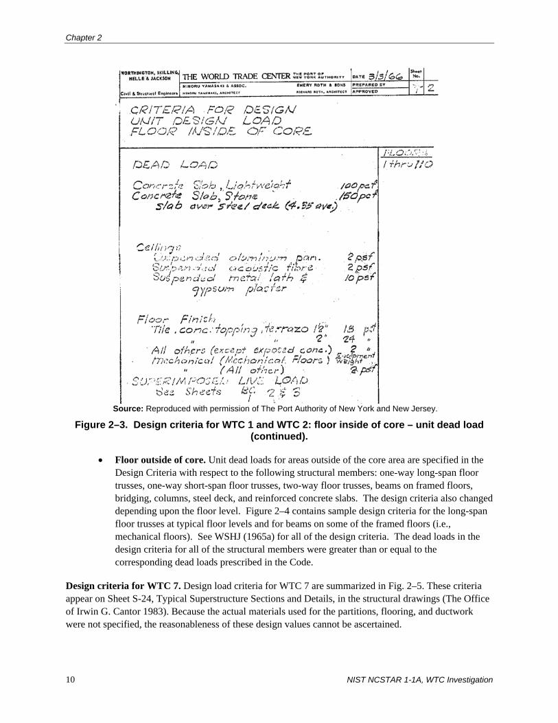
Chapter 2
10 NIST NCSTAR 1-1A, WTC Investigation
Source: Reproduced with permission of The Port Authority of New York and New Jersey.
Figure 2–3. Design criteria for WTC 1 and WTC 2: floor inside of core – unit dead load (continued).
• Floor outside of core. Unit dead loads for areas outside of the core area are specified in the Design Criteria with respect to the following structural members: one-way long-span floor trusses, one-way short-span floor trusses, two-way floor trusses, beams on framed floors, bridging, columns, steel deck, and reinforced concrete slabs. The design criteria also changed depending upon the floor level. Figure 2–4 contains sample design criteria for the long-span floor trusses at typical floor levels and for beams on some of the framed floors (i.e., mechanical floors). See WSHJ (1965a) for all of the design criteria. The dead loads in the design criteria for all of the structural members were greater than or equal to the corresponding dead loads prescribed in the Code.
Design criteria for WTC 7. Design load criteria for WTC 7 are summarized in Fig. 2–5. These criteria appear on Sheet S-24, Typical Superstructure Sections and Details, in the structural drawings (The Office of Irwin G. Cantor 1983). Because the actual materials used for the partitions, flooring, and ductwork were not specified, the reasonableness of these design values cannot be ascertained.

Provisions Used to Design and Construct the Buildings
NIST NCSTAR 1-1A, WTC Investigation 11
Source: Reproduced with permission of The Port Authority of New York and New Jersey.
Figure 2–4. Design criteria for WTC 1 and WTC 2: floor outside of core – unit dead load.

Chapter 2
12 NIST NCSTAR 1-1A, WTC Investigation
Source: Reproduced with permission of The Port Authority of New York and New Jersey.
Figure 2–4. Design criteria for WTC 1 and WTC 2: floor outside of core – unit dead load (continued).

Provisions Used to Design and Construct the Buildings
NIST NCSTAR 1-1A, WTC Investigation 13
Source: Reproduced with permission of The Port Authority of New York and New Jersey.
Figure 2–5. Design load criteria for WTC 7. Live Loads
Code requirements. Requirements for live loads are given in sub-article 902.0, Live Loads, of the Code, with specific requirements for floor live loads given in C26-902.2. Minimum design values for uniformly distributed and concentrated floor live loads for various occupancies are contained in Reference Standard RS 9-2, Minimum Requirements for Uniformly Distributed and Concentrated Live Loads (C26-902.2). For occupancies that are not listed, design live loads are to be determined by the architect or engineer subject to approval by the Building Commissioner. Provisions are also given on how to apply concentrated live loads so as to produce maximum stress.
Design criteria for WTC 1 and WTC 2. Specified live loads are given in the Design Criteria for WTC 1 and WTC 2 (WSHJ 1965a). As in the case of dead loads, different live load criteria were established for members located inside the core and outside the core. Samples from the Design Criteria are shown in this report.
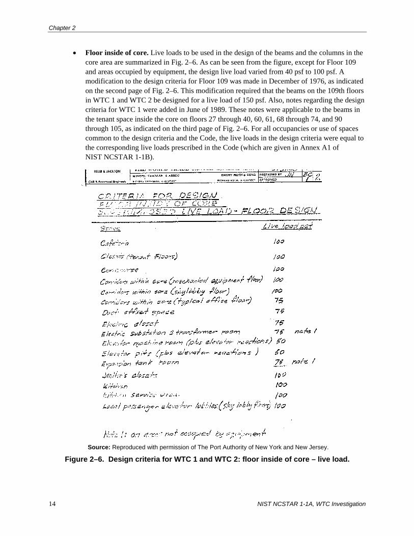
Chapter 2
14 NIST NCSTAR 1-1A, WTC Investigation
• Floor inside of core. Live loads to be used in the design of the beams and the columns in the core area are summarized in Fig. 2–6. As can be seen from the figure, except for Floor 109 and areas occupied by equipment, the design live load varied from 40 psf to 100 psf. A modification to the design criteria for Floor 109 was made in December of 1976, as indicated on the second page of Fig. 2–6. This modification required that the beams on the 109th floors in WTC 1 and WTC 2 be designed for a live load of 150 psf. Also, notes regarding the design criteria for WTC 1 were added in June of 1989. These notes were applicable to the beams in the tenant space inside the core on floors 27 through 40, 60, 61, 68 through 74, and 90 through 105, as indicated on the third page of Fig. 2–6. For all occupancies or use of spaces common to the design criteria and the Code, the live loads in the design criteria were equal to the corresponding live loads prescribed in the Code (which are given in Annex A1 of NIST NCSTAR 1-1B).
Source: Reproduced with permission of The Port Authority of New York and New Jersey.
Figure 2–6. Design criteria for WTC 1 and WTC 2: floor inside of core – live load.

Provisions Used to Design and Construct the Buildings
NIST NCSTAR 1-1A, WTC Investigation 15
Source: Reproduced with permission of The Port Authority of New York and New Jersey.
Figure 2–6. Design criteria for WTC 1 and WTC 2: floor inside of core – live load (continued).

Chapter 2
16 NIST NCSTAR 1-1A, WTC Investigation
Source: Reproduced with permission of The Port Authority of New York and New Jersey.
Figure 2–6. Design criteria for WTC 1 and WTC 2: floor inside of core – live load (continued).

Provisions Used to Design and Construct the Buildings
NIST NCSTAR 1-1A, WTC Investigation 17
Source: Reproduced with permission of The Port Authority of New York and New Jersey.
Figure 2–6. Design criteria for WTC 1 and WTC 2: floor inside of core – live load (continued).

Chapter 2
18 NIST NCSTAR 1-1A, WTC Investigation
Source: Reproduced with permission of The Port Authority of New York and New Jersey.
Figure 2–6. Design criteria for WTC 1 and WTC 2: floor inside of core – live load (continued).

Provisions Used to Design and Construct the Buildings
NIST NCSTAR 1-1A, WTC Investigation 19
• Floor outside of core. Like the unit dead loads, design live loads outside of the core area varied with respect to the floor level. At most floor levels, a design live load of 100 psf was specified for the slabs (see Fig. 2–7 from the Design Criteria). Note that this live load is greater than the 50 psf live load specified in the Code for office occupancies without storage. At mechanical floors 7, 41, 75, and 108, a 75-psf live load was used (also see Fig. 2–4). Figure 2–8 contains sample design criteria for the columns at the floor levels noted in the figure. In this case, live loads specified in the design criteria were equal to the corresponding live loads prescribed in the Code. Design live loads for the floor trusses, which are specified in the Design Criteria, are discussed in the following section on live load reductions.
Source: Reproduced with permission of The Port Authority of New York and New Jersey.
Figure 2–7. Design criteria for WTC 1 and WTC 2: typical floor slabs outside of core – live load.
Design criteria for WTC 7. As noted previously, design criteria for WTC 7 are summarized in Fig. 2–5. These criteria appear on Sheet S-24, Typical Superstructure Sections and Details, in the structural drawings (The Office of Irwin G. Cantor 1983). For the floor levels where the type of occupancy was noted on Sheet S-24, the live loads in the design criteria were equal to those given in the Code.
Live Load Reduction
In general, building codes allow live loads to be reduced below code-prescribed values, since it is unlikely that an entire floor area will be fully loaded with the design live loads. For example, the probability is small that a column in the lowest floor of a multistory building would have to carry the full code-prescribed live load on all of the supported floors above. The same is true for floor members, such as beams or trusses, that support live loads on only one supported floor: smaller live loads are expected on

Chapter 2
20 NIST NCSTAR 1-1A, WTC Investigation
members that support larger floor areas. It is important to note that codes generally limit the maximum amount of live load reduction that may be taken on a member (depending on the type of member, the area it supports, and the type of live load) and that live load reduction is not permitted in all situations.
Source: Reproduced with permission of The Port Authority of New York and New Jersey.
Figure 2–8. Design criteria for WTC 1 and WTC 2: columns outside of core – live load.
Code requirements. Provisions for live load reduction are contained in sub-article 903.0, Live Load Reduction. According to C26-903.1, live load reduction is not permitted on roofs. The allowable reduced live load for floor members is determined by multiplying the basic live load value from Reference Standard RS 9-2 (see above) by the percentages given in Table 9-1 of the Code, which is reproduced here as Table 2–1. These percentages are a function of the contributory floor area, which is defined in C26-903.3, and the ratio of live load to dead load. Contributory floor areas are computed as follows (C26-903.3):
• For one-way and two-way slabs: product of the shorter span length and a width equal to one-half the shorter span length. Ribbed slabs shall be considered as though the slabs were solid.
• For flat plate or flat slab construction: one-half the area of the panel.

Provisions Used to Design and Construct the Buildings
NIST NCSTAR 1-1A, WTC Investigation 21
• For columns, girders, or trusses framing into columns: the loaded area directly supported by the column, girder, or truss. For columns supporting more than one floor, the loaded area shall be the cumulative total area of all the floors that are supported.
• For joists and similar multiple members framing into girders or trusses, or minor framing around openings: twice the loaded area directly supported but not more than the area of the panel in which the framing occurs.
Table 2–1. Percentage of live load per the 1968 Code. Ratio of Live Load to Dead Loada
Contributory Area (ft2) 0.625 or less 1 2 or more
149 or less 100 100 100 150–299 80 85 85 300–449 60 70 75 450–599 50 60 70 600 or more 40 55 65
a. For intermediate values of live load/dead load, the applicable percentages of live load may be interpolated.
No live load reduction is permitted (C26-903.2(b)) for members and connections (other than columns, piers, and walls) supporting:
• Floor areas used for storage (including warehouses, library stacks, and record storage);
• Areas used for parking of vehicles; and
• Areas used as places of assembly, for manufacturing, and for retail or wholesale sales.
The maximum live load reduction is 20 percent for columns, piers, and walls supporting such areas.
Live load reduction is also not permitted for calculating shear stresses at the heads of columns in flat slab or flat plate construction (C26-903.2(c)).
As an alternative procedure, live load reduction for columns, piers, and walls may be taken as 15 percent on the top floor, increased successively at the rate of 5 percent on each successive lower floor, with a maximum reduction of 50 percent. For girders supporting 200 ft2 or more of floor area, the live load reduction is 15 percent.
Design criteria for WTC 1 and WTC 2. Sample live load reduction criteria from the Design Criteria of WTC 1 and WTC 2 are given in Fig. 2–9 (WSHJ 1965a). According to these criteria, live load reductions were to be determined in accordance with C26-348.0 (note: this is the section number of the live load reduction provisions in the 1938 edition of the Code) subject to the modifications contained in Fig. 2–9. It is important to note that the live load reduction provisions in C26-348.0 of the 1938 Code are the same as the alternative provisions contained in C26-903.2(d) of the 1968 Code, except for the provisions related to permissible reductions for certain types of occupancies, which are more comprehensive and more stringent in the 1968 Code.

Chapter 2
22 NIST NCSTAR 1-1A, WTC Investigation
Source: Reproduced with permission of The Port Authority of New York and New Jersey.
Figure 2–9. Design criteria for WTC 1 and WTC 2 – live load reduction.
Figure 2–10 shows the percentage of design live load from the Design Criteria that was to be used in the design of beams in the core area, except for tenant areas, on the floors noted in the figure. These percentages were the same as those from the 1968 Code (see Table 2–1 of this report), except in the case where the live load to dead load ratio was 2 or more and the loaded area tributary to the floor member was between 150 ft2 and 299 ft2; in this case, the code-prescribed percentage is 85 percent, while the value in the Design Criteria was 90 percent, which is more stringent than the Code requirement.

Provisions Used to Design and Construct the Buildings
NIST NCSTAR 1-1A, WTC Investigation 23
Source: Reproduced with permission of The Port Authority of New York and New Jersey.
Figure 2–10. Design criteria for WTC 1 and WTC 2: floors inside of core, except for tenant areas – live load reduction.
Figure 2–11 shows the design live loads from the Design Criteria for the tenant areas inside of the core. The solid line represents the reduced live load that was to be used in the design of the beams; these values were computed in accordance with the live load reduction provisions in the Design Criteria (see Item b in Fig. 2–9). Note that the unreduced live load specified in the Design Criteria for tenant spaces inside the core was 100 psf (see Fig. 2–6), which matches the design live load shown in Fig. 2–11 for tributary areas up to 200 ft2. No live load reduction was to be taken for beams with tributary areas less than 200 ft2 in tenant areas Also included in this figure are two other sets of data points: one set represents the reduced live load computed in accordance with the 1968 Code provisions with a live-to-dead load ratio equal to

Chapter 2
24 NIST NCSTAR 1-1A, WTC Investigation
one (see Table 2–1), and the other set is the Code equivalent uniform load for partitions, which is a constant 6 psf for partition weights up to 100 plf (see Exhibit RS 9-1 in Annex A1 of NIST NCSTAR 1-1B). The Code requires a 50-psf live load in tenant areas (office areas without storage) per Reference Standard RS 9-2 (see Exhibit RS 9-2 in Annex A1 of NIST NCSTAR 1-1B). The 50 psf live load plus the 6 psf partition load is shown in the figure for tributary areas up to 150 ft2. Figure 2–11 clearly shows that the design live loads specified in the Design Criteria, including live load reduction, were greater than those required by the Code for office areas without storage.
Source: Reproduced with permission of The Port Authority of New York and New Jersey.
Figure 2–11. Design criteria for WTC 1 and WTC 2: floors inside of core, tenant areas – live load reduction.

Provisions Used to Design and Construct the Buildings
NIST NCSTAR 1-1A, WTC Investigation 25
The sheets from the Design Criteria that are shown in Fig. 2–12 give the design dead and live loads for the floor trusses (short-span, long-span, and two-way) outside of the core area for the floors that are noted in the figure. The Design Criteria also specified a live load equal to 100 psf that could act over an area of 6 ft-6 in. by 31 ft-0 in. on any of the long-span or short-span trusses in the system.
Source: Reproduced with permission of The Port Authority of New York and New Jersey.
Figure 2–12. Design criteria for WTC 1 and WTC 2: floors outside of core.

Chapter 2
26 NIST NCSTAR 1-1A, WTC Investigation
Figure 2–13 is a reproduction of sheet TF 1/16 from the Design Criteria, which shows the design live loads, including live load reduction, on the short-span, long-span, and two-way floor trusses in the area outside of the core for the floor levels that are noted in the figure. Similar criteria were also provided for other floor levels.
The live load reduction criteria for columns outside of the core area are summarized in Fig. 2–14.
Source: Reproduced with permission of The Port Authority of New York and New Jersey.
Figure 2–13. Design criteria for WTC 1 and WTC 2: floors outside of core – live load reduction.

Provisions Used to Design and Construct the Buildings
NIST NCSTAR 1-1A, WTC Investigation 27
Source: Reproduced with permission of The Port Authority of New York and New Jersey.
Figure 2–14. Design criteria for WTC 1 and WTC 2: columns outside of core – live load reduction.
Design criteria for WTC 7. Live load reduction criteria used in the design of the structural members in WTC 7 are not listed on any of the structural drawings. However, the project specifications (WTC 7 Project Specifications 1984) require that WTC 7 be designed in accordance with the NYC Building Code. No documents were found that indicated what live load reduction was used.

Chapter 2
28 NIST NCSTAR 1-1A, WTC Investigation
Wind Loads
Code requirements. According to sub-article 904.0, Wind Loads, wind forces are computed in accordance with Reference Standard RS 9-5, Minimum Design Wind Pressures. The Code provisions require that wind shall be assumed to act from any direction, and for continuous framing, the effects of partial loading conditions shall be considered. Minimum design wind pressures acting on vertical surfaces are contained in Table RS 9-5-1, which is reproduced here as Table 2–2.
Table 2–2. Design wind pressures on vertical surfaces per the 1968 Code (Table RS 9-5-1).
Design Wind Pressure on Vertical Surfaces (psf of projected solid surface) Height Zone
(ft above curb level) Structural Frame Glass Panels
0 – 50a 15 – 0 – 100 20 30 101 – 300 25 30 301 – 600 30 35 601 – 1000 35 40 Over 1000 40 40
a. Signs and similar construction of shallow depth only.
Table RS 9-5-2 (see Table 2–3) contains the design wind pressures normal to horizontal and inclined surfaces.
Table 2–3. Design wind pressures on horizontal and inclined surfaces per the 1968 Code (Table RS 9-5-2).
Roof Slope Design Wind Pressure Normal to Surface 30 degrees or less
Either pressure or suction equal to 40 % of the values in Table RS 9-5-1 over the entire roof area.
More than 3 degrees
Windward slope: pressure equal to 60 % of the values in Table RS 9-5-1. Leeward slope: suction equal to 40 % of the values in Table RS 9-5-1.
For purposes of design, pressures on vertical, horizontal, and inclined surfaces of the building are to be applied simultaneously.
For the design of wall elements other than glass panels (i.e., mullions, muntins, girts, panels, and other wall elements including their fastenings), the Code design wind pressure, which includes allowances for gust, acting normal to wall surfaces is specified as 30 psf pressure or as 20 psf suction for all heights up to 500 ft. Applicable design pressures for heights over 500 ft are to be determined from a special investigation, but are not allowed to be less than those pressures indicated in Table RS 9-5-1.
Minimum design wind pressures are also given for other building elements; they are to be obtained by multiplying the pressures in Table RS 9-5-1 by the appropriate shape factors in Table RS 9-5-3. The

Provisions Used to Design and Construct the Buildings
NIST NCSTAR 1-1A, WTC Investigation 29
shape factors vary from 0.7 for upright, circular cylindrical surfaces to 2.0 for signs with less than 70 percent solid surface.
In lieu of using the wind pressures mentioned above, design wind pressures may be established by “suitably conducted model tests,” subject to review and approval of the Building Commissioner (Item 6 in Reference Standard RS 9-5). The tests are to be based on a basic (fastest-mile) wind velocity of 80 mph at 30 ft above ground, and are to simulate and include all factors involved in consideration of wind pressure, including pressure and suction effects, shape factors, functional effects, gusts, and internal pressures and suctions.
Design criteria for WTC 1 and WTC 2. Design wind forces on the towers were determined based on a series of wind tunnel tests that were conducted at the Colorado State University (CSU) and the National Physical Laboratory in the United Kingdom. Specific details on these tests can be found in Secs. 2.3.2 and 3.2 of this report.
Design wind pressures were specified in the WTC Design Criteria for external cladding and glazing (WSHJ 1965a). Outward (negative) pressure acting normal to the surface varied from 65 psf below the 7th floor to 125 psf at the 109th floor. Inward (positive) pressures varied from 45 psf below the 7th floor to 55 psf at the 108th floor. These pressures are based on the results of a series of wind tunnel tests that were performed specifically for this purpose (WSHJ 1967a).
Design criteria were also established for the antenna mast located on top of WTC 1 (WSHJ 1973). The antenna and its components were to be designed for the following conditions:
• A mean wind speed of 140 mph in any direction and no ice coating;
• A mean wind speed of 110 mph in any direction with an ice coating of 1/2 in. over all exposed unheated metallic surfaces with a minimum air temperature of 20 °F;
• A mean wind speed of 110 mph in any direction and no ice coating under a range of air temperatures from 10 °F to 90 °F;
• A mean wind speed of 40 mph in any direction and no ice coating under a range of air temperatures from –15 °F to 105 °F; and
• The dynamic effects of wind associated with the mean wind speeds specified above (dynamic effects of wind gusts were obtained by multiplying the mean wind forces by a factor of 5).
The requirement of a 1/2 in. thick coating of ice matches the requirement in C26-905.6 of the Code for the design of open-framed or guyed towers. Also, the Code requires that exterior exposed frames, arches, or shells be designed for the forces and/or movements resulting from an increase or decrease in temperatures of 60 °F for metal construction (C26-905.7). These requirements are less stringent than those contained in the design criteria. It is not evident from the documents how the wind velocities in the specification were established. The design criteria contain a section on how the wind forces were computed based on these velocities.
The effects of wind on the towers were investigated throughout the years as part of the Structural Integrity Inspection program. The results from these investigations are discussed in detail in NIST NCSTAR 1-1C
Chapter 2
30 NIST NCSTAR 1-1A, WTC Investigation
(This reference is to one of the companion documents from this Investigation. A list of these documents appears in the Preface to this report).
Design criteria for WTC 7. No design criteria or calculations were available for WTC 7 with respect to wind loads. However, a wind tunnel study of WTC 7 was carried out in 1983 by the University of Western Ontario at the request of the structural engineer of record, Irwin G. Cantor, Consulting Engineers (Isyumov 1983). No document is available to show how the wind tunnel test results were used in the design of WTC 7.
Changes in Design Loads
Over the years, the loads imposed on the buildings changed, primarily due to changes in occupancy. Design guidelines were issued by the Port Authority that pertained to tenant modifications, and included allowable design loads that could be applied to the buildings. These guidelines are described in detail in Maintenance and Modifications to Structural Systems of WTC 1, 2, and 7 (NIST NCSTAR 1-1C). Information on the major structural changes in WTC 1, 2, and 7 can also be found in NIST NCSTAR 1-1C.
2.2.2 Structural Design Requirements of the Code
The following discussion focuses on the design requirements in the Code as they relate to the design and construction of the WTC buildings. Only those requirements that are applicable to the structural design of the members in the WTC buildings are covered. Methods used to proportion structural members and other components of the buildings are contained in Sec. 2.3 of this report.
General Requirements
Code sub-article 1000.0, Scope and General Requirements, contains the minimum requirements for materials, design, and construction of structural elements in buildings. NIST NCSTAR 1-1B describes these minimum requirements. The inspection requirements given in Table 10-1 (Inspection of Materials and Assemblies) and Table 10-2 (Inspection of Methods of Construction) and the material requirements in sub-articles 1003.0 through 1011.0 must be satisfied. Reference Standard RS-10, Structural Work, which contains a list of referenced national standards, is part of the general requirements (C26-1000.2, Standards). The list of national standards that were applicable to the design of the WTC buildings can be found in Annex A1 of NIST NCSTAR 1-1B. For example, reference was made to the 1963 edition of Specification for the Design, Fabrication, and Erection of Structural Steel for Buildings (AISC 1963b), which was applicable to the design of WTC 1 and WTC 2. The 1978 edition of the specification was applicable to steel design in WTC 7 (AISC 1978).
Design methods and materials other than those prescribed in the Code were allowed to be used, as long as it could be demonstrated to the Building Commissioner that the design would provide a factor of safety against structural failure consistent with the requirements established for the different building materials of construction in sub-articles 1003.0 through 1011.0.
The Code required a signed statement of satisfaction from the architect or engineer when structural elements were detailed on shop or working drawings prepared by someone other than the architect or

Provisions Used to Design and Construct the Buildings
NIST NCSTAR 1-1A, WTC Investigation 31
engineer. Manufacturers were also required to provide statements or other supporting documentary evidence of accreditation attesting to the accuracy of fire-resistance ratings data, load tables, or similar data supplied in catalogues.
General Structural Design Requirements
The general structural design requirements in sub-article 1001.0 cover, among other things, secondary stresses, combination of loads, and deflection limitations.
• C26-1001.3, Secondary stresses. Secondary stresses in trusses must be considered in design.
• C26-1001.4, Combination of loads. Dead loads, live loads (including impact), and reduced live loads are defined in this section as basic loads. Loads of infrequent occurrence are wind forces, thermal forces, shrinkage, and unreduced live loads (where live load reduction is permitted by Article 9). Load combinations depend on whether the working stress method or the ultimate strength method is used to proportion the members.
Where design is based on allowable or working stresses, the loads in Article 9 (discussed above) are to be multiplied by the following factors: (1) for combinations of basic loads only, the factor shall be 1.0; (2) for any combination of one or more basic loads with any one load of infrequent occurrence, the factor shall be 0.75; and (3) for any combination of one or more basic loads with two or more loads of infrequent occurrence, the factor shall be 0.67. The requirements related to the allowable unit stresses for short-time loading design of wood members are given as an exception to these requirements. NIST NCSTAR 1-1B contains the specific load combinations for the building materials used in the WTC towers.
Where design is based on ultimate strength criteria (including plastic design of steel structures and proportioning of suspended structures), the loads prescribed in Article 9 are to be multiplied by the factors given in C26-1010.5(e) (allowable working loads for suspended structures, if applicable) and the applicable material reference standards. Two exceptions are given: (1) where load factors are given for wind (or earthquake) forces in reference standards, the design must additionally consider combinations of loads that include the other loads of infrequent occurrence substituted for the wind loads and (2) the design shall also consider combinations of loads where the two most critical loads of infrequent occurrence are combined with the basic loads. The load factors in the reference standards and in C26-1010.5(e) for suspended structures may be reduced 15 percent for the combination of basic loads plus one load of infrequent occurrence.
• C26-1001.5, Deflection limitations. Vertical deflection limitations for floor and roof assemblies are provided in the referenced material standards for structural steel and concrete (see Sec. 5.10 of NIST NCSTAR 1-1B). In addition to those requirements, the total deflection due to dead load plus live load (including the effects of creep and shrinkage) of members supporting walls, veneered walls, or partitions constructed of or containing panels of masonry, glass, or other frangible materials is limited to the span length divided by 360. No horizontal deflection or drift limitations due to lateral wind forces are prescribed in the Code.

Chapter 2
32 NIST NCSTAR 1-1A, WTC Investigation
Adequacy of the Structural Design
According to sub-article 1002.0, Adequacy of the Structural Design, the design of structural members is to conform to the applicable material standards mentioned in sub-articles 1003.0 through 1011.0 (C26-1002.1). If such computations as prescribed in these standards cannot be executed due to “practical difficulties,” the structural design can be deemed adequate if the member or assembly performs satisfactorily when subjected to load tests in accordance with 1002.4(a). Provisions to determine the adequacy of completed or partially completed structures are also provided. Prequalifying load tests (C26-1002.4(a)) can be used to establish the strength of a member or assembly prior to having such members or assemblies incorporated into a structure. The test specimens are to be a true representation of the actual members or assemblies in all aspects, including the type and grade of material used. Support conditions for the members or assemblies being tested are to simulate the conditions of support in the building, except that conditions of partial fixity might be approximated by conditions of full or zero restraint, whichever produces a more severe stress condition in the member being tested. In regard to strength requirements, the member or assembly must be capable of supporting the following (note: no specific reference to a particular type of building material is given in this section of the Code):
1. Without visible damage (other than hairline cracks) its own weight plus a test load equal to 150 percent of the design live load plus 150 percent of any dead load that will be added at the site, and
2. Without collapse its own weight plus a test load equal to 50 percent of its own weight plus 250 percent of the design live load plus 250 percent of any dead load that will be added at the site.
The latter loading is to remain in place for a minimum period of one week, and all loading conditions in Article 9 of the Code are to be considered. Exceptions to the above load conditions are also given in this section.
The member or assembly is also subject to the following deflection requirements: the recovery of the deflection caused by the superimposed loads listed in item 1 above must be at least 75 percent. Also, the deflection under the design live load is limited to the values prescribed in C26-1001.5.
Requirements are also given for tests on models less than full size. The similitude, scaling, and validity of the analysis are to be attested to by an officer or principal of the firm or corporation making the analysis. The firm or corporation is to be approved by the Building Commissioner.
Concrete Requirements
According to sub-article 1004.0, design of reinforced concrete structural members is to conform to the requirements in that section and Reference Standard RS 10-3, which is the 1963 edition of Building Code Requirements for Reinforced Concrete (ACI 1963) with modifications, which is applicable to the design of WTC 1 and WTC 2. One notable modification made to this standard is that all of the requirements under ACI 318 Secs. 902 (Design loads) and 903 (Resistance to wind, earthquake, and other forces) are deleted and replaced with the following: “Building code requirements for loads and infrequent stress conditions shall apply.” “Infrequent stress conditions” refer to such conditions as wind and earthquake. In other words, all loads are to be determined in accordance with the 1968 Code. In case of concrete

Provisions Used to Design and Construct the Buildings
NIST NCSTAR 1-1A, WTC Investigation 33
structures designed by the ultimate strength design method, design (factored) loads are to be determined in accordance with Sec. 1506 of ACI 318-63.
According to the specifications for WTC 7 (WTC 7 Project Specifications 1984), the 1983 edition of ACI 318 was applicable (ACI 1983).
Steel Requirements
Design of steel structural members is to conform to the requirements in sub-article 1005.0 and Reference Standard RS 10-5, which is the 1963 edition of Specification for the Design, Fabrication, and Erection of Structural Steel for Buildings (AISC 1963b) with modifications, which is applicable to the design of WTC 1 and WTC 2. Similar to the design of reinforced concrete members, the provisions of Sec. 1.3 (Loads and Forces) are deleted and replaced with the following: “The provisions of the building code for loads shall apply.” Other notable modifications to the AISC Specification are:
• The following paragraph is added to the definition of composite construction in Sec. 1.11.1: “Concrete materials shall meet the applicable requirements of the building code. Where concrete having a unit weight less than 130 pcf is used, the capacity of the shear connectors to resist applied load under the proposed conditions of use shall be investigated…”
• Sec. 1.25.5 on field connections during erection is deleted and replaced with the following: “…No holes, copes or cuts of any type shall be made to facilitate erection unless specifically shown on the shop drawings or authorized in writing by the party or parties designated for inspection of such work.”
Reference Standards RS 10-6 and 10-7 are to be used for light gage cold formed steel and open web steel joists, respectively (see NIST NCSTAR 1-1B).
According to the specifications for WTC 7 (WTC 7 Project Specifications 1984), the 1978 edition of the AISC Specification was applicable (AISC 1978).
2.3 SUMMARY OF METHODS USED TO PROPORTION STRUCTURAL MEMBERS AND COMPONENTS
2.3.1 Overview
This section contains the general methods that were used to proportion the structural members and components in the buildings. Since design calculations were not available for WTC 7, the discussion that follows covers the design methods employed for WTC 1 and WTC 2.
A summary of the design methods is provided for the following structural members in WTC 1 and WTC 2: exterior columns, floor trusses outside of the core area, composite steel beams in the core area, connections, concrete floor slabs, steel deck, and hat trusses.

Chapter 2
34 NIST NCSTAR 1-1A, WTC Investigation
2.3.2 Exterior Columns
An approximate method was used to estimate the shear forces and bending moments acting on exterior columns (and spandrels) due to the effects of wind (WSHJ 1966a). In general, design shear forces and overturning moments were computed at each floor level from an equivalent design wind velocity at the top of the tower and average pressure coefficients that were derived over the height of the tower from the wind tunnel tests (see Sec. 3.2 in this report for details on the wind tunnel tests). The equivalent design wind velocity was defined as the mean wind velocity averaged over a 20 min period at a height of 1,500 ft above the ground and was based on a 50 year return period (WSHJ 1966c).
A Weibull probability distribution function was used to predict the maximum deflection (static plus dynamic deflections) at the top of a tower as a function of return period (see Sec. 3.2 of this report for more details). From the wind tunnel tests, maximum deflections were recorded at the top of a tower for a number of different wind velocities acting in 24 different directions (i.e., 15 degree intervals) around the towers. The equivalent design wind velocity designV was calculated from the following equation, using a test wind velocity of 100 mph (WSHJ 1966a):
max
50100AA
Vdesign = (2–1)
where:
A50 = deflection at the top of the tower in the North South or East West direction based on the Weibull probability distribution function using a return period of 50 years
Amax = maximum deflection at the top of the tower in the North South or East West direction obtained from the wind tunnel tests due to a wind velocity equal to 100 mph
Equivalent design wind velocities for both towers in both directions are contained in Table 18 of the wind report, which is reproduced here as Table 2–4. It can be seen from the table that the equivalent 20 min design wind velocity was approximately 98 mph in the N-S and E-W directions for both buildings.
Table 2–4. Equivalent design wind velocity for WTC 1 and WTC 2.a
Tower
Direction of
Movement
50-year Displacement
(ft)
Critical Direction
for 100 mph Windb
Maximum Deflection in Critical Direction
(ft)
Equivalent Design Wind
Velocity (mph)
N-S 4.30 70° 4.5 98.0 1
E-W 3.54 0° 3.7 98.0
N-S 4.64 80° 5.0 96.3 2
E-W 3.66 170° 4.1 95.0 a. Based on critical damping ratio = 2.5 %. b. Measured clockwise from north; zero angle corresponds to wind blowing from north to south.

Provisions Used to Design and Construct the Buildings
NIST NCSTAR 1-1A, WTC Investigation 35
The shear forces S and overturning moments M at each floor level due to the equivalent design wind velocity in each of the principal directions were comprised of static and dynamic components:
MMM
SSS
′±=
′±= (2–2)
where the first terms in the summations are the mean or steady-state components and the second terms are dynamic components. Mean shear forces and overturning moments at height z above the base, which were derived from the average pressure coefficients measured in the wind tunnel tests at the CSU on the static twin-tower model, were calculated from the following equations in each principal direction (WSHJ 1966a):
)(21)(
)(21)(
22
2
zCDHVzM
zDHCVzS
Mo
So
ρ=
ρ= (2–3)
where:
ρ = design air density = 0.0023 slugs/ft3
oV = mean design wind velocity = 98 mph
SC = shear force coefficients from wind tunnel tests (WSHJ 1965b)
MC = overturning moment coefficients from wind tunnel tests (WSHJ 1965b)
D = plan dimension of building
H = height of building
Dynamic components of the shear forces and overturning moments at any height z, which were based on the peak dynamic amplitudes of vibration measured in the wind tunnel tests at CSU on the aeroelastic twin-tower model, were calculated from the following equations in each principal direction (WSHJ 1966a):
dzzSzM
dzzzmAnzS
Hz
Hzo
)()(
)()(4)( 22
∫
∫
′=′
μπ=′ (2–4)
In the first of these equations, on is the natural frequency of oscillation of the building, which is given in the wind report (WSHJ 1966a), and A is the amplitude of oscillation at the top of the tower corresponding to a mean design wind velocity of 98 mph. The quantity )(zm is the mass per unit height of the building (see Fig. 121 in WSHJ 1966a) and )(zμ is the mode amplitude at height z for unit amplitude at the top of the building (see Fig. 120 in WSHJ 1966a).

Chapter 2
36 NIST NCSTAR 1-1A, WTC Investigation
As noted above, 24 wind directions at 15 degree intervals around the towers were considered in the analysis. Since there were four possible combinations of static and dynamic components due to wind (see Eq. 2–2), 96 sets of wind load cases were considered for each tower (WSHJ 1966c). A summary of the total deflections and dynamic amplitudes at the top of the towers and the adjusted pressure coefficients over the height of the towers is contained in WSHJ (1966c). Figure 2–15 shows the total (static plus dynamic) deflections at the top of WTC 1 (A) and WTC 2 (B) in both the north-south and east-west directions due to wind velocities of 100 mph and 98 mph (design wind speed; see Table 2–4). Through interpretation of information contained in documents provided by Leslie E. Robertson Associates (LERA) in July 2004, it is possible to determine the design wind pressures from the wind tunnel tests.
Source: WSHJ 1966c. Reproduced with permission of The Port Authority of New York and New Jersey.
Figure 2–15. Total deflections (ft) at top of WTC 1 and WTC 2 due to wind.

Provisions Used to Design and Construct the Buildings
NIST NCSTAR 1-1A, WTC Investigation 37
Once the total shear forces were computed at each floor level, concentrated forces due to wind were determined and applied at each floor level. Member forces were computed based on these applied forces.
Typical hand calculations for an exterior column are given in WSHJ (1967b). These calculations are representative of the allowable stress methods used to proportion exterior columns throughout the towers. The first two pages of the calculations are contained in Fig. 2–16. As can be seen from the figure, Formula (7a) from Sec. 1.6.1 (Combined Stresses, Axial Compression and Bending) of the AISC Specification (AISC 1963b) was used to proportion the members for the design loads contained in the tables on the second page of the calculations. For given section properties of the columns, the required yield strength of the steel was determined from Formula (7a).
2.3.3 Floor Trusses
Design data for the composite floor trusses that were used outside of the core area are given in Laclede Steel Company (1967). Four pages from this document, which are contained in Fig. 2–17, summarize the loads, materials, design equations, shear connectors, and deflection criteria used in design. As shown on the third page in the figure, truss members with lengths less than or equal to 24 in. were designed for allowable tension and compression stresses per AISC Specification Secs. 1.5.1.1 (Tension) and 1.5.1.3 (Compression), respectively (AISC 1963b). Top chord members with lengths greater than 24 in. were designed for combined axial and bending stresses per Sec. 1.6.1 (Combined Axial Compression and Bending).
Floor truss panel points were connected by electronically controlled resistance welds providing at least two times the strength of the connected members at full design load (Laclede Steel Company 1967).
As shown in Fig. 2–18, truss seat connection capacities were tabulated for connections at the core and at the exterior columns (SHCR 1971). The governing capacity, which was to be determined in accordance with the AISC Specification (AISC 1963b) per the Design Criteria (WSHJ 1965a), was taken as the smallest of the capacities of the members and connectors that made up a particular connection.

Chapter 2
38 NIST NCSTAR 1-1A, WTC Investigation
Source: Reproduced with permission of The Port Authority of New York and New Jersey.
Figure 2–16. Design method for exterior columns in WTC 1 and WTC 2.

Provisions Used to Design and Construct the Buildings
NIST NCSTAR 1-1A, WTC Investigation 39
Source: Reproduced with permission of The Port Authority of New York and New Jersey.
Figure 2–16. Design method for exterior columns in WTC 1 and WTC 2 (continued).

Chapter 2
40 NIST NCSTAR 1-1A, WTC Investigation
Source: Reproduced with permission of The Port Authority of New York and New Jersey.
Figure 2–17. Design method for floor trusses in WTC 1 and WTC 2.

Provisions Used to Design and Construct the Buildings
NIST NCSTAR 1-1A, WTC Investigation 41
Source: Reproduced with permission of The Port Authority of New York and New Jersey. Figure 2–17. Design method for floor trusses in WTC 1 and WTC 2 (continued).

Chapter 2
42 NIST NCSTAR 1-1A, WTC Investigation
Source: Reproduced with permission of The Port Authority of New York and New Jersey. Figure 2–17. Design method for floor trusses in WTC 1 and WTC 2 (continued).

Provisions Used to Design and Construct the Buildings
NIST NCSTAR 1-1A, WTC Investigation 43
Source: Reproduced with permission of The Port Authority of New York and New Jersey. Figure 2–17. Design method for floor trusses in WTC 1 and WTC 2 (continued).

Chapter 2
44 NIST NCSTAR 1-1A, WTC Investigation
Source: Reproduced with permission of The Port Authority of New York and New Jersey.
Figure 2–18. Tabulation of component capacities of floor truss connections in WTC 1 and WTC 2.

Provisions Used to Design and Construct the Buildings
NIST NCSTAR 1-1A, WTC Investigation 45
Source: Reproduced with permission of The Port Authority of New York and New Jersey.
Figure 2–18. Tabulation of component capacities of floor truss connections in WTC 1 and WTC 2 (continued).

Chapter 2
46 NIST NCSTAR 1-1A, WTC Investigation
2.3.4 Composite Steel Beams
“Design standards” for the composite floor systems in the core area are given in the Design Criteria (WSHJ 1965a), and are summarized in Fig. 2–19. As seen on the first page in the figure, the provisions for effective flange width of the concrete slab were modified from those given in Sec. 906(d) (Requirements for T-beams) of the 1963 edition of ACI 318 (ACI 1963) to accommodate the case that is depicted in the figure. Design of the composite members followed Sec. 1.11 (Composite Construction) in the AISC Specification (AISC 1963b).
Source: Reproduced with permission of The Port Authority of New York and New Jersey.
Figure 2–19. Design standard for composite sections in WTC 1 and WTC 2.

Provisions Used to Design and Construct the Buildings
NIST NCSTAR 1-1A, WTC Investigation 47
Source: Reproduced with permission of The Port Authority of New York and New Jersey.
Figure 2–19. Design standard for composite sections in WTC 1 and WTC 2 (continued).

Chapter 2
48 NIST NCSTAR 1-1A, WTC Investigation
Source: Reproduced with permission of The Port Authority of New York and New Jersey.
Figure 2–19. “Design standard” for composite sections in WTC 1 and WTC 2 (continued).
Allowable horizontal shear loads for the connectors in “stone concrete,” which are shown on sheet number 4 in the figure, are taken directly from Table 1.11.4 in the AISC Specification (AISC 1963b). According to Commentary Sec. 1.11.4 (Shear Connectors), the allowable shear loads for connectors in concrete with aggregates not conforming to ASTM C 336 must be established by a suitable testing program. Note that the allowable shear loads for the connectors in “lightweight concrete” used in design are 85 percent of the values listed for “stone concrete” (see Fig. 2–19). The Port Authority requested tests to be performed (based on a test program established by Skilling, Helle, Christiansen, & Robertson) at the Fritz Engineering Laboratory at Lehigh University to determine the shear capacity of 3/4 in. diameter by 4 1/2 in. long studs welded through the troughs of Roll Form Type “B” steel deck in lightweight
6 This specification defines the requirements for grading and quality of fine and coarse aggregate (other than lightweight or
heavyweight aggregate) for use in concrete.

Provisions Used to Design and Construct the Buildings
NIST NCSTAR 1-1A, WTC Investigation 49
aggregate concrete with a compressive strength of 3,000 psi (see Sec. 3.5 of this report). Results from this testing program could not be located, and no evidence was found that this system was utilized in WTC 1 and WTC 2. The floor trusses outside of the core area did not use shear studs to make them composite with concrete slab. Instead, truss diagonals were extended above the top chord; this “knuckle” acted like a shear stud (see Sec. 5.4 of this report).
2.3.5 Connections
General design standards for the A325 bolts used in the connections are given in the Design Criteria (WSHJ 1965a) and are shown in Fig. 2–20. Page numbers from the Manual of Steel Construction (AISC 1963a) (which also contains the AISC Specification) are given in the figure for bolt dimensions and properties and for allowable loads.
Source: Reproduced with permission of The Port Authority of New York and New Jersey.
Figure 2–20. Design standard for bolted connections in WTC 1 and WTC 2.
Specifications for welded connections depended on the structural members that were being connected. In particular, the specifications in the contracts with the suppliers of the floor trusses, box core columns and built-up beams, exterior wall, and rolled columns and beams each contained requirements that the welding conform as a minimum to the provisions in the then current edition of Code for Welding in Building Construction, D1.0, American Welding Society (see Chapters 5 and 6 of this report for more information on the requirements in these contracts). For the exterior columns, the welding electrodes that were to be used depended on the lower yield strength of the plates that were joined (see Sheet 2-AB2-3 in WSHJ 1967c, which is reproduced here in Fig. 2–21).

Chapter 2
50 NIST NCSTAR 1-1A, WTC Investigation
A connection manual was assembled by WSHJ that contained tables and charts with allowable loads for the typical connections used in the project (WSHJ 1967d).
Source: Reproduced with permission of The Port Authority of New York and New Jersey.
Figure 2–21. Schedule of welding electrodes for connections in exterior columns in WTC 1 and WTC 2.
A note on structural drawing sheet S-24 of WTC 7 references the “AISC Beam Tables” for connection design of composite and non-composite beams (The Office of Irwin G. Cantor 1983). As noted in Sec. 2.1.2 of this report, the project specifications for WTC 7 (WTC 7 Project Specifications 1984) required that the structural steel be designed in accordance with the then current New York City Building Code and the latest edition of the AISC Specification for the Design, Fabrication, and Erection of Structural Steel for Buildings (AISC 1963a).

Provisions Used to Design and Construct the Buildings
NIST NCSTAR 1-1A, WTC Investigation 51
2.3.6 Concrete Floor Slabs
According to the first general note for structural concrete contained in Book 8 of the structural drawings for WTC 1 and WTC 2 (WSHJ 1967c), all structural concrete was to conform to the 1963 edition of ACI 318 (ACI 1963), except where specifically modified, supplemented, or superseded by the Specifications or specific notes in the drawings (see Fig. 2–22).
Source: Reproduced with permission of The Port Authority of New York and New Jersey.
Figure 2–22. General notes for structural concrete in WTC 1 and WTC 2.
The ultimate strength method was used in concrete design (see general note 6 in Fig. 2–22). The basic requirement for strength design may be expressed as follows:
Required Strength ≤ Design Strength, or
U ≤ φ (Nominal Strength) (2–5)
where the required strength (U) is determined from the load combinations given in Sec. 1506, the nominal strength is determined in accordance with the provisions in Chapters 15 through 19, and the capacity

Chapter 2
52 NIST NCSTAR 1-1A, WTC Investigation
reduction factors (φ) are obtained from Sec. 1504, where all section and chapter numbers are from ACI 318 (ACI 1963). The load combinations in Sec. 1506 of ACI 318-63 are summarized as follows:
• U = 1.5D + 1.8L
• U = 1.25(D + L + W)
• U = 0.9D + 1.1W
where
D = effects of the dead loads
L = effects of the live loads
W = effects of the wind forces
Additional assumptions used in the design of the floor slabs are contained in the Design Criteria (WSHJ 1965a), as shown in Fig. 2–23.
Source: Reproduced with permission of The Port Authority of New York and New Jersey.
Figure 2–23. Design assumptions for concrete floor slabs in WTC 1 and WTC 2.

Provisions Used to Design and Construct the Buildings
NIST NCSTAR 1-1A, WTC Investigation 53
Calculations for the slab design on floors 10 through 87 (WSHJ 1967e) as well as concrete design tables (WSHJ 1967f) confirm the use of the ultimate strength design method. Figure 2–24 shows sample calculations for the one-way slab design based on this design method.
Source: Reproduced with permission of The Port Authority of New York and New Jersey.
Figure 2–24. Reinforced concrete one-way slab design in WTC 1 and WTC 2.

Chapter 2
54 NIST NCSTAR 1-1A, WTC Investigation
Specifications for the reinforcing steel used in the concrete members are given on structural drawing 8-AB1-2.2 (WSHJ 1967c), and are reproduced here in Fig. 2–25.
Source: Reproduced with permission of The Port Authority of New York and New Jersey.
Figure 2–25. Specification for reinforcing steel used in WTC 1 and WTC 2.
2.3.7 Steel Deck
The design criteria for the steel deck used in the composite floor system are in the Design Criteria (WSHJ 1965a) and are shown in Fig. 2–26.
2.3.8 Hat Trusses
A series of diagonal members together with the building columns and floor members formed hat trusses between the 107th floor and the roof in WTC 1 and WTC 2. Six trusses ran parallel to the long direction, and eight trusses ran parallel to the short direction of the core.

Provisions Used to Design and Construct the Buildings
NIST NCSTAR 1-1A, WTC Investigation 55
Source: Reproduced with permission of The Port Authority of New York and New Jersey.
Figure 2–26. Design criteria for steel deck in WTC 1 and WTC 2.
According to the 1995 Structural Integrity Inspection report that was written by LERA, “the hat trusses…control individual column expansion and contraction due to uneven column temperatures” (LERA 1995). Additionally, the hat trusses in WTC 1 provided stability for the 362 ft tall TV mast that was centered on the top of that tower. The hat trusses in both buildings were designed to support one large mast or four smaller towers near the perimeter of the core region. The 1995 report also noted that the horizontal members of the hat trusses were composite with the concrete floor slabs, which made the concrete floor slabs a vital component of the hat trusses.
Design calculations for the different types of trusses that were used are contained in SHCR (1969). Members in the trusses were designed for axial forces or axial forces plus bending moments due to the combined effects of gravity loads (including the weight of the TV mast) and wind loads. Typical calculations for a truss running in the north-south direction in WTC 1 are shown in Fig. 2–27. These calculations are representative of the allowable stress methods used to proportion the members in the trusses. As can be seen from the figure, the AISC Specification (AISC 1963b) was used to proportion the members for the design loads contained on the first page of the calculations. No calculations were found that showed how the trusses controlled column expansion and contraction due to uneven temperatures, as discussed in the 1995 report by LERA.

Chapter 2
56 NIST NCSTAR 1-1A, WTC Investigation
Source: Reproduced with permission of The Port Authority of New York and New Jersey.
Figure 2–27. Design method for hat trusses in WTC 1 and WTC 2.

Provisions Used to Design and Construct the Buildings
NIST NCSTAR 1-1A, WTC Investigation 57
Source: Reproduced with permission of The Port Authority of New York and New Jersey.
Figure 2–27. Design method for hat trusses in WTC 1 and WTC 2 (continued).

Chapter 2
58 NIST NCSTAR 1-1A, WTC Investigation
2.4 REFERENCES
ACI (American Concrete Institute). 1963. Building Code Requirements for Reinforced Concrete. Detroit, MI.
ACI (American Concrete Institute). 1983. Building Code Requirements for Reinforced Concrete. Detroit, MI.
AISC (American Institute of Steel Construction). 1963a. Manual of Steel Construction. Sixth edition. New York, NY.
AISC (American Institute of Steel Construction). 1963b. Specification for the Design, Fabrication, and Erection of Structural Steel for Buildings. New York, NY.
AISC (American Institute of Steel Construction). 1978. Specification for the Design, Fabrication, and Erection of Structural Steel for Buildings. Chicago, IL.
Isyumov, N., and M. Poole. 1983. A Study of Wind Effects for the No. 7 World Trade Center, New York, N.Y. BLWT–SS21–1983. Boundary Layer Wind Tunnel Laboratory, The University of Western Ontario. London, Ontario, Canada.
Laclede Steel Company. 1967. World Trade Center Floor Grid Trusses Basic Design Data, structural calculations. February. (WTCI-75-I).
LERA (Leslie E. Robertson and Associates). 1995. World Trade Center Structural Integrity Inspection – Hat Truss between Floor 107 and the Roof. February. (part of WTCI-66-L).
SHCR (Skilling, Helle, Christiansen, & Robertson). 1969. Structural calculations for floors 107 to 110 (part of WTCI-271-L).
SHCR (Skilling, Helle, Christiansen, & Robertson). 1971. Truss seat connection capacities. (RD-4, No. 0458, 233 Park Avenue).
The City of New York. 1968. The City of New York Building Code.
The Office of Irwin G. Cantor. 1983. Structural drawings for WTC 7. (WTCI-25-S, Disk 1 of 3).
WSHJ (Worthington, Skilling, Helle, & Jackson). 1965a. Design Criteria for WTC 1 and 2. (WTCI-2-L and part of WTCI-50-L).
WSHJ (Worthington, Skilling, Helle, & Jackson). 1965b. The World Trade Center – Wind Program Interim Report, Supplement No. 4. January. (WTCI-558-L).
WSHJ (Worthington, Skilling, Helle, & Jackson). 1966a. Part III, Final Chapter, WSHJ Wind Report. July. (part of WTCI-68-L).
WSHJ (Worthington, Skilling, Helle, & Jackson). 1966b. Part II, Final Chapter, WSHJ Wind Report. July. (part of WTCI-68-L).

Provisions Used to Design and Construct the Buildings
NIST NCSTAR 1-1A, WTC Investigation 59
WSHJ (Worthington, Skilling, Helle, & Jackson). 1966c. Wind Loading on Exterior Walls of WTC Towers. (WTCI-393-L).
WSHJ (Worthington, Skilling, Helle, & Jackson). 1967a. Part IV, Final Chapter, WSHJ Wind Report. February. (part of WTCI-68-L).
WSHJ (Worthington, Skilling, Helle, & Jackson). 1967b. Design Calculations, Exterior Column Segments, El. 318-363, structural calculations. February. (WTCI-368-L).
WSHJ (Worthington, Skilling, Helle, & Jackson). 1967c. Structural drawings of WTC 1 and 2. (WTCI-50-L).
WSHJ (Worthington, Skilling, Helle, & Jackson). 1967d. Connection Manual. (Box CCC 233 Park Avenue).
WSHJ (Worthington, Skilling, Helle, & Jackson). 1967e. Slab design – 10th to 87th floor, structural calculations. (WTCI-468-L).
WSHJ (Worthington, Skilling, Helle, & Jackson). 1967f. Structural calculations for slab design. (WTCI-631-L).
WSHJ (Worthington, Skilling, Helle, & Jackson). 1973. Structural Design Specification – Antenna Masts on the North & South Tower of the World Trade Center. (part of WTCI-50-L).
WTC 7 Project Specifications. 1984. (WTCI-187-P).

Chapter 2
60 NIST NCSTAR 1-1A, WTC Investigation
This page intentionally left blank.

NIST NCSTAR 1-1A, WTC Investigation 61
Chapter 3 TESTS PERFORMED TO SUPPORT DESIGN INNOVATIONS
3.1 EXTERIOR WALL PANEL TESTS
Scaled model tests were performed at the University of Western Ontario to determine load-deflection characteristics of typical exterior wall panel units along the height of the building (Gardner 1966). One of the main goals of these tests was to determine how the overall stiffness of the wall panels changed as changes were made in the sizes of the members that made up the wall panels (i.e., columns, spandrels, and stiffeners). According to the report, it was anticipated that the results from these tests would help in determining the “most effective construction” for the wall panels.
In lieu of testing a typical wall panel, which was comprised of three columns and three spandrels, subassembly ABCD depicted in Fig. 3–1 was tested. According to the report, this subassembly was chosen for its simplicity, flexibility, and low cost. Models were built to a scale of one-quarter of full size and were fabricated from sheets of thermoplastic. The following advantages of using thermoplastic sheet were listed in the report: (1) it has a low modulus of elasticity, which produced large deflections for comparatively small loads, (2) it possesses linear stress-strain characteristics, similar to structural steel, and (3) it is easily machined and can be easily joined.
Source: Gardner 1966. Reproduced with permission of The Port Authority of New York and New Jersey.
Figure 3–1. Subassembly used for testing external wall panel in WTC 1 and WTC 2.
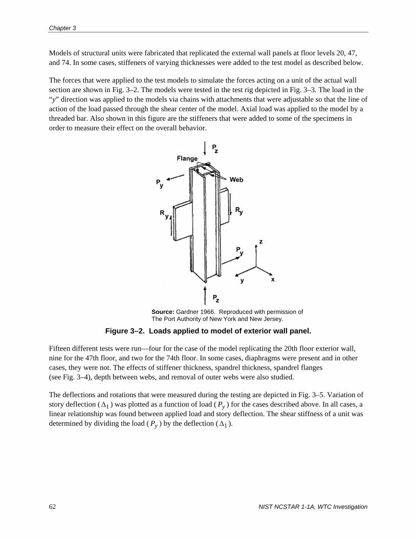
Chapter 3
62 NIST NCSTAR 1-1A, WTC Investigation
Models of structural units were fabricated that replicated the external wall panels at floor levels 20, 47, and 74. In some cases, stiffeners of varying thicknesses were added to the test model as described below.
The forces that were applied to the test models to simulate the forces acting on a unit of the actual wall section are shown in Fig. 3–2. The models were tested in the test rig depicted in Fig. 3–3. The load in the “y” direction was applied to the models via chains with attachments that were adjustable so that the line of action of the load passed through the shear center of the model. Axial load was applied to the model by a threaded bar. Also shown in this figure are the stiffeners that were added to some of the specimens in order to measure their effect on the overall behavior.
Source: Gardner 1966. Reproduced with permission of The Port Authority of New York and New Jersey.
Figure 3–2. Loads applied to model of exterior wall panel.
Fifteen different tests were run—four for the case of the model replicating the 20th floor exterior wall, nine for the 47th floor, and two for the 74th floor. In some cases, diaphragms were present and in other cases, they were not. The effects of stiffener thickness, spandrel thickness, spandrel flanges (see Fig. 3–4), depth between webs, and removal of outer webs were also studied.
The deflections and rotations that were measured during the testing are depicted in Fig. 3–5. Variation of story deflection ( 1Δ ) was plotted as a function of load ( yP ) for the cases described above. In all cases, a linear relationship was found between applied load and story deflection. The shear stiffness of a unit was determined by dividing the load ( yP ) by the deflection ( 1Δ ).

Tests Performed to Support Design Innovations
NIST NCSTAR 1-1A, WTC Investigation 63
Source: Gardner 1966. Reproduced with permission of The Port Authority of New York and New Jersey.
Figure 3–3. Test rig used for testing model of external wall panels in WTC 1 and WTC 2.
Source: Gardner 1966. Reproduced with permission of The Port Authority of New York and New Jersey.
Figure 3–4. Spandrel flanges used in some test models of exterior wall panels.

Chapter 3
64 NIST NCSTAR 1-1A, WTC Investigation
Source: Gardner 1966. Reproduced with permission of The Port Authority of New York and New Jersey.
Figure 3–5. Displacements and rotations measured during model test program of exterior wall panels.
The following conclusions from these tests were reported:
• Stiffeners are necessary for enhanced performance, but the thickness of the stiffeners is not critical.
• Axial loads do not appear to affect the shear stiffness of the model.
• Spandrel flanges do not contribute to the shear stiffness of the model.
• The distance between the webs of the column should be the longest possible.
• The thickness of the spandrel increases the shear stiffness of the unit.
• The depth of the spandrel increases the shear stiffness of the unit.
• Increasing the thicknesses of either the column webs and/or the column flanges increases the torsional stiffness of the model.
• Distortion due to twisting can be reduced by using thicker stiffeners.

Tests Performed to Support Design Innovations
NIST NCSTAR 1-1A, WTC Investigation 65
3.2 WIND TUNNEL TESTS
Wind tunnel tests were part of a four-pronged wind program that was developed by Worthington, Skilling, Helle & Jackson (WSHJ) for the design of the World Trade Center (WTC) (WSHJ 1964). The elements of this program were:
• Meteorological Program. The purpose of this program was to determine mean wind speeds, return periods, the magnitude of wind shear and gradient, the directional characteristics of the wind, and the energy spectra of wind gusts that were expected at the site of the WTC.
• Wind Tunnel Program. The goals of this program were to (a) develop a physical model of lower Manhattan and subject the model to wind velocities obtained from the meteorological program, (b) obtain static and dynamic responses of the WTC towers, (c) study construction problems (no additional information on this could be found in the documentation), and (d) study the effect of the structural parameters on the integrity of the towers.
• Structure Damping Program. The main objectives of this program were to determine the critical damping ratio of the structural system and to determine ways of increasing this ratio.
• Physiological Program. The objective of this program was to determine acceptable levels of response to wind-induced excitations as measured by perception levels of a cross-section of the population.
The meteorological and wind tunnel programs are discussed in an 8-volume set of reports written by the structural engineer, WSHJ. These reports are referenced in the following sections of this report. No documentation was found on the structure damping program or the physiological program.
3.2.1 Meteorological Program
One of the basic requirements of the meteorological program was the acquisition of data from sources that measured wind velocity (WSHJ 1965a). According to the WSHJ report, both the mean wind speed and turbulence characteristics were key items that needed to be determined. Air density corresponding to the extreme wind, a statistical distribution of wind speeds, and changes of wind velocity with respect to direction were other parameters that were needed as well.
The report points out that earlier studies of extreme wind speeds, including those carried out for the American Society of Civil Engineers (ASCE 1961), were not adequate for the design of the WTC towers for the following reasons (WSHJ 1965a):
• They were general studies that did not address the specific environment at the site of the WTC.
• They did not consider surface roughness to have an influence on wind speeds.
• They did not relate specifically to building heights comparable to the WTC.

Chapter 3
66 NIST NCSTAR 1-1A, WTC Investigation
• They used wind speed parameters, such as the fastest-mile wind, that were not completely appropriate for the WTC.
• They did not consider variations of extreme wind speed with respect to direction.
In order to help in determining the extreme average wind speed that was expected at the top of the towers, data from the following sources were examined:
• Annual maximum hourly average wind speed (1912–1958), annual maximum 5 min average wind speed (1912–1958), and fastest-mile wind speed (1912–1959) from the U.S. Weather Bureau Station at the Whitehall Building in lower Manhattan, which was less than a half mile from the WTC site.
• Annual maximum hourly average wind speed from the Brookhaven National Laboratory (1954–1964). Included were data relating to wind profile and hurricanes.
• Annual maximum hourly average wind speeds from weather stations on the Atlantic seaboard in the Maritime Provinces of Canada for all years of record.
• Annual fastest-mile wind speed for all U.S. Weather Bureau Stations on the eastern seaboard from Atlantic City, New Jersey, to Eastport, Maine, for all years since 1912.
• Records of surface winds from balloons launched at John F. Kennedy (JFK) Airport (1956–1964). Balloons were released and observed every 6 h.
A statistical model for estimating the extreme wind velocity was developed based on a Fisher-Tippet Type I theoretical distribution. It was reported that the agreement between the observed distributions based on the data from the above locations and the theoretical distribution was satisfactory.
A study was also performed to determine a suitable mean wind velocity profile as a function of surface roughness. The following relationship was reported to adequately represent the distribution of wind speed with respect to height and exposure based on the data from the Brookhaven National Laboratory, the balloon study at JFK Airport, and the results from the wind tunnel tests:
α= ⎟⎟
⎠
⎞⎜⎜⎝
⎛
GG
zzz
V
V (3–1)
where:
zV = wind velocity at height z
GV = gradient wind velocity at height Gz
The constants Gz and α that were used in the study, which depend on the exposure, are given in Table 3–1.

Tests Performed to Support Design Innovations
NIST NCSTAR 1-1A, WTC Investigation 67
Table 3–1. Constants used in wind study of WTC 1 and WTC 2.
Exposure α Gz (ft)
Southeast direction (over Brooklyn)
0.30 1,250
Southwest direction (over open water)
0.17 1,100
One other conclusion that was reported was that the wind speed at the top of the WTC towers was expected to be approximately 1.65 times greater than the wind speed at 355 ft above ground measured at the Brookhaven National Laboratory, based on Eq. 3–1.
A suitable averaging period for the design wind speed was also studied. In lieu of using averaging periods that were used in routine meteorological observations (5 min average, hourly average, fastest-mile), the report concluded that an averaging period should be selected considering the aerodynamic behavior of the towers and the wind tunnel tests. A 20 min averaging period was selected based on the following considerations:
• Based on wind tunnel observations, a 20 min averaging time allowed steady-state response of the towers to develop.
• The sampling period used in the Colorado State University (CSU) wind tunnel tests generally corresponded to approximately 20 min.
An empirical relationship was developed for maximum wind speeds averaged over different periods. It was shown that the 20 min average wind speed was expected to be approximately 10 percent greater than the hourly average wind speed.
Based on a comparison of estimates of actual wind speeds obtained from the five sources noted above (i.e., Whitehall Building, Brookhaven National Laboratory, Canadian weather stations, U.S. weather stations, and JFK Airport), the following equation is given for the design 20 min mean wind speed rV in miles per hour at the top of the towers for any return period r in years (WSHJ 1965a):
⎥⎦
⎤⎢⎣
⎡⎟⎠⎞
⎜⎝⎛ −−−=
rV eer
11loglog1190 (3–2)
A study on air density was performed at the Whitehall Building. This study suggested that an appropriate design value was 0.0024 slugs/ft3 at the bottom of the towers and 0.0023 slugs/ft3 at the top of the towers. These values were used to correct the wind tunnel results that were carried out at CSU.
The directionality of wind speeds was estimated from the balloon data at JFK Airport. It was found that winds were stronger from westerly and northerly quadrants, and that those from the southeast were the weakest. It was also observed that the direction of the strongest winds changed with height. On average, the wind direction changed approximately 15 degrees between the surface and the top of the towers for the westerly wind quadrants and about 25 degrees for the easterly quadrants. According to the report, these results were significant in the estimation of wind pressures on the towers.

Chapter 3
68 NIST NCSTAR 1-1A, WTC Investigation
Part III of the Final Chapter of the WSHJ Wind Report (WSHJ 1966a) re-examined the design wind velocity equation presented in Supplement #3 of the Wind Program Interim Report (see Eq. 3–2 above), since it was evident from the wind tunnel tests, which are discussed in the next section of this report, that the response of the towers was highly sensitive to wind direction. It was reported that wind velocities based on a Weibull probability distribution P(V) closely fit the observations recorded at John F. Kennedy Airport for wind velocities V greater than 16 m/s (36 mph):
7.1
5.101)(⎟⎠⎞
⎜⎝⎛
−−=
V
eVP (3–3)
where the velocity V in Eq. 3–3 is in meters per second.
Wind velocities less than 16 m/s (36 mph) were reported to have had only a small influence on the structural performance of the towers. According to the report, the Weibull distribution produced slightly conservative values for wind velocities at the top of the towers assuming that these velocities were equally likely from all directions, even though from the observed data, there appeared to be a higher probability of stronger winds from the northwest and a relatively lower probability of the same from the southeast. Wind velocities based on a Weibull distribution were also reported to adequately predict the maximum static plus dynamic deflections at the tops of the towers in both principal directions, which were obtained from the CSU wind tunnel tests. As discussed in Sec. 2.3.2 above, these deflections were used to determine the forces in the exterior columns and spandrels.
In order to obtain representative measurements of wind in the neighborhood of the WTC, anemometers were mounted on the New York Telephone Building and the 40 Wall Street Building, which were both in close proximity to the WTC site in lower Manhattan. These sites, as well as the wind directions used in the wind tunnel tests, are depicted in Fig. 3–6 (WSHJ 1966b). The information from these measurements was used to adjust the characteristics of air flow in the wind tunnel tests, especially with respect to turbulence. Wind tunnel tests indicated that the velocity of the wind at the New York Telephone Building was similar to that at the same elevation at the WTC site. More details on the results of this study are contained in WSHJ (1966b).
3.2.2 Wind Tunnel Program
Wind tunnel tests were conducted at CSU and the National Physical Laboratory (NPL), located in Teddington, Middlesex, United Kingdom. Tests were conducted on single-tower and twin-tower configurations subject to uniform and turbulent flow conditions. A description of the tests conducted at both locations follows.
Tests Conducted at CSU
Over 2,000 tests were conducted at the CSU Microclimatological Wind Tunnel to study the behavior of static and aeroelastic models (WSHJ 1964). All work took place in the long test section, which made it possible to develop a boundary layer in the tunnel (WSHJ 1965b). The directions chosen for the wind tunnel testing of the models of lower Manhattan corresponded to the most turbulent (southeast direction over Brooklyn) and the least turbulent (southwest over open water) directions.
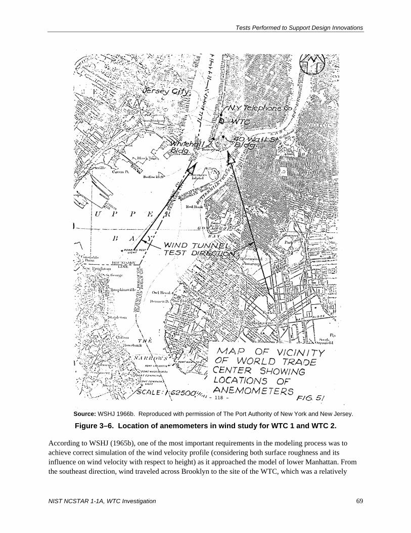
Tests Performed to Support Design Innovations
NIST NCSTAR 1-1A, WTC Investigation 69
Source: WSHJ 1966b. Reproduced with permission of The Port Authority of New York and New Jersey.
Figure 3–6. Location of anemometers in wind study for WTC 1 and WTC 2.
According to WSHJ (1965b), one of the most important requirements in the modeling process was to achieve correct simulation of the wind velocity profile (considering both surface roughness and its influence on wind velocity with respect to height) as it approached the model of lower Manhattan. From the southeast direction, wind traveled across Brooklyn to the site of the WTC, which was a relatively

Chapter 3
70 NIST NCSTAR 1-1A, WTC Investigation
rough urban area. From the southwest, wind traveled mainly across open water. To simulate these conditions in the tunnel at CSU, the Brooklyn fetch was represented by a bed of 1/4 in. to 1/2 in. gravel, while the open water fetch was simulated by coarse emery cloth. Also, as discussed in Sec. 3.2.1, the mean wind velocity profile defined by Eq. 3–1 above was used.
Aside from wind velocity, the principal variables in the wind tunnel tests were the following (WSHJ 1964):
• Spacing of towers
• Number of towers
• Damping
• Wind direction
• Boundary layer characteristics
• Relative stiffnesses of the models
It was found that the models oscillated in the wind due to vortex shedding, gust buffeting, and wake buffeting under certain combinations of the above variables.
Two hundred tests were run at CSU to study the effect of tower spacing on the response of the buildings. It was concluded that the “as planned” spacing was satisfactory.
Aeroelastic tests and measurements of steady pressure for single-tower and twin-tower configurations in uniform flow (i.e., insignificant level of turbulence) constituted a major portion of the tests that were run at CSU (WSHJ 1965c). Part of the purpose of these tests was to provide a comparison between the performance of the models at CSU and at the NPL (Whitbread and Scruton 1965). The report concluded that the aeroelastic tests at the two locations were in good qualitative and quantitative agreement.
The aeroelastic tests were designed to determine the predominant sway motion (i.e., deflections or amplitudes) of the towers and to provide a check of the steady-state component of the overturning moment at the base. To determine the pressure distribution on the towers, tests were conducted using models with pressure points along a regular grid. From these tests, shear forces and overturning moments were obtained along the height of the towers.
Three aeroelastic models of the towers were constructed at CSU using a scale of 1/500, which was dictated by the size of the wind tunnel. The basic components of the models included: (1) a rigid exterior shell fabricated from Sitka spruce (a wood having high stiffness to weight properties), (2) spring elements at the base that provided stiffness ratios about the two horizontal axes that corresponded to the full-scale structures, and (3) a damping unit that provided levels of structural damping between about 0.8 and 100 percent of critical damping (WSHJ 1965c). The model was based on preliminary studies that indicated that the largest amplitudes of the buildings would be associated with the fundamental mode of oscillation and that the shape of the fundamental mode corresponded approximately to a straight line. Deformations were measured by strain gauges mounted on the model. Wind velocities were gradually increased during the tests. Readings were taken for wind velocities up to 200 mph in the case of the low-

Tests Performed to Support Design Innovations
NIST NCSTAR 1-1A, WTC Investigation 71
frequency models and up to 140 mph in the case of the high-frequency models at 15 degree azimuth intervals, except when large amplitudes were encountered; in those situations, readings were taken at 5 degree intervals. A discussion on the low- and high-frequency models used in the study is given later in this section of the report.
Models used for the pressure tests at the CSU were constructed of clear acrylic plastic at a scale of 1/500, the same scale used in the aeroelastic tests (WSHJ 1965d). Approximately 75 pressure taps were mounted on the pressure models, and test results were obtained for the single tower (0 degrees to 45 degrees) and the twin towers (0 degrees to 180 degrees).
During the tests, pressure differences were determined between pressures measured at points on the model and the datum ambient pressure in the tunnel. Local pressure coefficients pC were defined by the following equation:
221
REF
REFp
V
PPC
ρ
−=
(3–4)
where P and REFP are the absolute pressures on the model and at the reference point, respectively, 2/2
REFVρ is the reference velocity pressure, and REFV is the wind velocity in miles per hour applied on the model. An averaging process was used to determine average pressure coefficients on the tower in the two principal directions (see Figs. 17a through 17e in WSHJ [1965c]). From these average pressure coefficients, shear force and overturning moment coefficients were obtained with respect to height. A comparison of aerodynamic coefficients of overturning moments derived from steady pressure tests and from aeroelastic model tests is given in Fig. 18 of WSHJ (1965c). It was reported that the results from these tests were in good agreement. The results from the CSU tests were also compared to those obtained at the NPL, and as noted above, the report states that results from these two sets of tests were in good qualitative and quantitative agreement.
The tests also indicated that large lateral deflections at the top of the building occurred for wind velocities in the range of 125 mph to 130 mph for angles of incidence within approximately 10 degrees of normal (see Fig. 3–7). The results are plotted in Figs. 19 and 20 in WSHJ (1965c). The deflections showed a consistent dependence on the degree of damping and were shown to be inversely proportional to the damping ratio.

Chapter 3
72 NIST NCSTAR 1-1A, WTC Investigation
10° 10°
10°
10°x x
y y
Produced largest displacement in x-direction
Produced largest displacement in y-direction
Wind
Wind
Source: WSHJ 1965c. Reproduced with permission of The Port Authority of New York and New Jersey.
Figure 3–7. Wind directions that produced the greatest displacements at the top of the tower during the wind tunnel tests.
Tests were also conducted at CSU using the southeast and southwest models of lower Manhattan subjected to turbulent flow conditions (WSHJ 1966c)1. Both single-tower and twin-tower configurations were considered. Definition of the grid system and tower configurations used in the tests is illustrated in Fig. 5 of WSHJ (1966c), which is reproduced here as Fig. 3–8. Also shown in the figure are the fundamental frequencies of the towers in the two principal directions in cycles per second (cps). Included in these tests were measurements of the maximum deflections at the tops of the towers (aeroelastic tests; wood models) and pressures along the height of the towers (thermoplastic models).
Similar to the other tests described above, test results for the single-tower model indicated that the most severe oscillations were transverse to the wind and occurred with the wind blowing within a small range of angles on either side of the normal to a face (see Figs. 9 through 13 in WSHJ [1966c]). The results also showed that an increase in turbulence, which was characteristic of the southeast model of lower Manhattan, appeared to suppress vortex shedding but gave rise to turbulence excitation with increased wind speed. Finally, it was observed that greater levels of damping reduced the dynamic response of the single tower in all cases, more so in uniform flow conditions than in turbulent conditions.
1 As noted in Sec. 3.2.1 of this report, it was found that winds were stronger from westerly and northerly quadrants. Wind from
the southeast direction was chosen in the wind tunnel program not because the velocity from this direction was the greatest, but because winds from this direction were the most turbulent (wind in this direction traveled over Brooklyn, which is a relatively rough urban area). Turbulence plays an important part in the dynamic excitation of structures, especially tall, slender structures. A fundamental discussion on turbulence and resulting aeroelastic phenomena can be found in Simiu and Scanlon (1996).

Tests Performed to Support Design Innovations
NIST NCSTAR 1-1A, WTC Investigation 73
Source: WSHJ 1966c. Reproduced with permission of The Port Authority of New York and New Jersey.
Figure 3–8. Definition of grid system and tower configurations for wind tunnel tests at CSU.
Test results for the twin-tower model are plotted in Figs. 14 through 29 in WSHJ (1966c). These graphs, which also include results from the wind tunnel tests conducted at the NPL (Whitbread 1967), give peak amplitudes of oscillation (deflections) at the tops of the towers for a range of wind velocities, wind directions, and degrees of damping for both the southeast and southwest models of lower Manhattan. In order to determine whether different time scales had an influence on the response of the towers due to wind velocity, two different time scales were considered in these tests. The first time scale was set equal to the model scale raised to the two-thirds power, i.e., (1/500)2/3 = 1/60. This time scale was used in what was referred to as the low-frequency model tests. The second time scale, which was used in the high-frequency tests, was set equal to 1/200. According to the report, with this time scale, the maximum wind velocity of the tunnel would coincide with the maximum wind velocity that could reasonably be expected. It was reported that since the natural frequency of vibration of the full-scale tower in the fundamental mode was close to 0.1 cps, the required frequency of vibration of the model corresponding to a time scale of 1/60 (i.e., low-frequency model) was 0.1/(1/60) = 6 cps. Similarly, the required frequency of vibration of the high-frequency model was 20 cps. These model frequencies were obtained by using different stiffnesses of the springs attached to the base of the models, as described previously.
0°

Chapter 3
74 NIST NCSTAR 1-1A, WTC Investigation
The following conclusions were made in the report on the test results for the twin-tower model (WSHJ 1966c):
• In all tests, deflections (peak amplitudes) at the tops of the towers increased monotonically with increasing wind velocity without any apparent peaks.
• At wind velocities below 150 mph, deflections at the tops of the towers from the southeast model of lower Manhattan tested at CSU and NPL were qualitatively similar and had about the same magnitude. At wind velocities greater than 150 mph, the largest deflections came from the NPL tests. At a wind velocity of approximately 175 mph, the NPL deflections were significantly larger. Deflections from the southwest model of lower Manhattan were less than those obtained from the southeast model of lower Manhattan tested at CSU and NPL, but were qualitatively similar.
• Comparison of the high-frequency and low-frequency tests conducted at CSU indicated that larger displacements occurred in the southwest model of lower Manhattan with the high-frequency models. Results from the southeast model of lower Manhattan indicated the opposite effect.
• The largest displacements in all tests were found to be with wind from the directions noted in Table 3–2 below.
Table 3–2. Wind directions that produced the largest displacements at the tops of the towers from the twin-tower wind tunnel tests. WTC 1 WTC 2
Building axis E-W N-S E-W N-S Wind directiona 0°, 150°, 180° 90° 0°, 180°, 330° 270°
a. See Figs. 3–7 and 3–8 for definition of wind direction angle, α. Source: WSHJ 1966c.
A comparison of the test results for the displacements at the top of WTC 1 in the north-south direction for wind blowing in the east-west direction (α = 90°, most severe case) is given in Fig. 30 of WSHJ (1966c) and is reproduced here in Fig. 3–9. Results were plotted for the southeast and southwest models of lower Manhattan obtained from tests at CSU as well as for those obtained from tests at NPL.
Based on the results obtained from the twin-tower wind tunnel tests, it was concluded in WSHJ (1966c) that the response of the WTC towers was governed by three aerodynamic factors: (1) Magnitude of the effective turbulence forces induced by the wind flow, (2) Magnitude of the effective forces induced by vortex shedding and turbulence in the structure’s own wake, and (3) Effective aerodynamic damping and coupling forces generated by the motion of the tower through the airflow. It was also noted that the effective mass, effective stiffness, the mode of vibration, and the mechanical damping of the towers influenced these factors.
A theoretical method was derived and was used to predict the dynamic behavior of the towers (WSHJ 1966c). Results from the theoretical models were compared to the results from the wind tunnel tests. A comprehensive discussion on this comparison can be found in WSHJ (1966c).

NIS
T NC
STA
R 1-1A
, WTC
Investigation 75
Tests P
erformed to S
upport Design Innovations
Source: WSHJ 1966c. Reproduced with permission of The Port Authority of New York and New Jersey.
Figure 3–9. Comparison of the variation of the N-S deflection (amplitude) of WTC 1 subjected to E-W wind for different degrees of damping (γ) and flow conditions.

Chapter 3
76 NIST NCSTAR 1-1A, WTC Investigation
The results from the wind tunnel tests were used in the design of the exterior columns and spandrels, which is discussed in Sec. 2.3.2 of this report.
The extensive wind tunnel testing that was performed to establish the lateral wind loads used in the design of WTC 1 and WTC 2 was state-of-the-art at that time.
Tests Conducted at NPL
Tests were performed on single-tower and twin-tower models at NPL to measure deflections at the tops of the towers in both smooth (uniform) flow and turbulent flow conditions (Whitbread and Scruton 1965). The models were constructed of light timber framework supported on diaphragms at 6 in. intervals from a central 2 in. diameter aluminum tube. The models had an external covering of plywood.
Principal differences between the CSU and NPL models were (WSHJ 1965c): (1) the model scale was 1/400 at the NPL compared to 1/500 at the CSU, (2) displacements were determined from output of accelerometers mounted near the tops of the models at NPL compared with strain gauges at CSU, and (3) displacements were recorded on a resetting digital voltmeter at the NPL compared with chart records at CSU. In the NPL tests, a grid of tubes in a plane normal to the wind stream was used to provide the required velocity profile over the height of the model. According to Whitbread and Scruton (1965), the velocity profile achieved in this manner was similar to that observed in the tests carried out at CSU on the model of lower Manhattan.
As noted previously, it was reported that the overall results obtained from the tests conducted at NPL were in good qualitative and quantitative agreement with those obtained from the tests performed at CSU.
3.3 DAMPING UNIT TESTS
Two testing programs were carried out to test certain important properties of the damping units. These programs were designed to help confirm the effectiveness and efficiency of the damping units in controlling building motion due to wind.
The Minnesota Mining and Manufacturing Company (3M) conducted the first set of tests in May 1967.2 Twenty-two full-size dampers were assembled and tested in accordance with the procedure outlined in Sec. III, paragraph b of the test report. The specimens, which were tested in a servo-controlled testing machine, were subjected to cyclic axial deformation in the form of a sine wave at 0.1 Hz frequency with a constant amplitude of 0.020 in. for 100 cycles. The specimens were also stretched or compressed monotonically at a steady rate of 0.5 in. per minute until they were “physically broken.” Although the number of tests that were run was insufficient for a rigorous statistical analysis, it was reported that the results confirmed that the damper mechanical properties would meet or exceed the minimum requirements prescribed in the specifications. The specifications for the damping units are given in Sec. 5.3.2 of this report.
2 Letter dated June 22, 1967 and enclosure from Don Caldwell of 3M to Peter Chen of SHCR (WTCI-501-L; reproduced in
Appendix B without appendices that are contained in WTCI-501-L).

Tests Performed to Support Design Innovations
NIST NCSTAR 1-1A, WTC Investigation 77
Dr. S. H. Crandall of the Massachusetts Institute of Technology conducted the second test program during 1968 and 1969.3 Thirty-nine prototypes, which consisted of the exterior column, the damping units, and the floor truss system, were tested in a manner that simulated the in-place conditions of the damping units.4 Twenty units were tested according to the test procedures previously established for the first series of test that were performed by 3M, which, as noted above, consisted of cycling tests and monotonic ultimate shear strength tests. Nineteen additional tests were performed to investigate the endurance capabilities of the specimens under conditions that were different from the aforementioned tests. In particular, these tests included variations in (1) amplitude and frequency of the applied cyclic axial deformation, (2) ambient temperature, and (3) a static preload superimposed on the simple harmonic loading. In all cases, the tests were performed in a specially built test frame, which was supposed to simulate the structural environment in which the damping units were to be placed (as noted above, the specimens were tested by 3M in a servo-controlled testing machine). In general, it was found that “…the energy absorbing capabilities of the elements are generally adequate to provide the expected damping under design conditions and that the elements do perform satisfactorily under limited variations of loading conditions, speed of oscillation, duration of oscillation, and ambient temperature.” It was reported, however, that specimens that were tested for ultimate shear strength would not meet the appropriate acceptance requirements of the design specifications (see Sec. 5.3.2 of this report), due to a large standard deviation.
A letter from Leslie Robertson of Skilling, Helle, Christiansen, & Robertson (SHCR) to Malcolm Levy of the Port of New York Authority (Port Authority or PONYA) discussed deficiencies in the test equipment used by Crandall, which may have had an effect on the test results.5 The possible influence of additional bolt holes, which were made in the specimens in order for them to fit the test jig, on the ultimate strength results obtained from this test program was noted in the SHCR review of the Crandall report (Crandall and Wittig 1969).6 A response from Crandall to this review provided a more comprehensive description of the testing machine that was used to determine the ultimate shear strength, since the report contained a “somewhat abbreviated explanation.”7 Additional testing of the damping units was also proposed by Crandall after the dampers had been installed in the towers in order to compare those results to those that were performed previously in the laboratory. No evidence has been found that indicates whether these tests were actually performed or not.
A report was produced by SHCR that compared the two testing programs.8 Table 1 in the report contains a summary of the methods employed in the two test programs, and Table 2 compares the results of the mechanical properties (dynamic stiffness, loss tangent, and ultimate strength) of the damping units. Major differences in test results occurred with respect to ultimate strength: the tests performed by 3M indicated that the ultimate strength of the units was satisfactory with respect to the design parameters (note: some of 3 “Test Program for World Trade Center Viscoelastic Damping Units,” by Stephen H. Crandall of MIT, May 20, 1968
(WTCI-501-L; see Appendix B). 4 “Test of Viscoelastic Damping Units for World Trade Center Tower Buildings,” S.H. Crandall and L.E. Wittig, April 23, 1969
(Box 9, 233 Park Ave.; see Appendix B). 5 Letter dated August 29, 1968 from Leslie E. Robertson of SHCR to Malcolm P. Levy of PONYA (WTCI-501-L; see
Appendix B). 6 Letter dated May 22, 1969 from Leslie E. Robertson of SHCR to Malcolm P. Levy of PONYA (WTCI-501-L; see
Appendix B). 7 Letter dated June 2, 1969 from Stephan H. Crandall of MIT to John M. Kyle of PONYA (WTCI-501-L; see Appendix B). 8 “World Trade Center Report No. DU-3, Viscoelastic Damping Units,” by SHCR, June 2, 1969 (WTCI-501-L; reproduced in
Appendix B without appendices that are contained in WTCI-501-L).

Chapter 3
78 NIST NCSTAR 1-1A, WTC Investigation
the information in the SHCR report, including design parameters, have been redacted), whereas, the tests performed by Crandall showed that about 20 percent of the damping units would be near or over the ultimate shear strength, which implies that they would fail in shear. According to the SHCR report, the reason for this discrepancy is not clear; however, the report goes on to state that perhaps this discrepancy is due to differences in the test set up used in the two programs.
During construction of WTC 1, a number of damper units were installed in November of 1970 and remained in place for almost a year, part of that time in unheated space. A request to test 12 of these damper units for loss factor and stiffness, fatigue, and ultimate strength was made by Malcolm Levy of the Port Authority to Don Caldwell of 3M.9 These tests were to help ascertain if cold temperatures during the winter had any affect on the mechanical properties of the damper units. No results from these tests have been found in any of the documentation.
The damper units were periodically tested as part of the Structural Integrity Inspection program. Results from that program are summarized in NIST NCSTAR 1-1C.
3.4 FLOOR TRUSS TESTS
3.4.1 Full-Scale Flexural Tests
According to Sec. 105.102 of the specification for the floor trusses, which was part of the contract between the Port Authority and Laclede Steel Company (PONYA 1967), full-scale load tests were to be performed on completely fabricated floor truss components. A minimum of one load test was required for each of the 23 different types of floor trusses designated in the design drawings. During testing, two equal concentrated test loads would be applied to the trusses in a test frame. Each load was to be applied at a panel point of the truss. For example, Fig. 3–10 shows the location of the concentrated loads that were applied during testing of 32 in. deep short-span, long-span, and two-way floor trusses.10 In WTC 1 or WTC 2, a floor truss would be subjected primarily to a uniformly distributed load on its top chord. Thus, since the tests were conducted using concentrated loads instead of uniformly distributed loads, the uniformly distributed loads had to be converted into equivalent concentrated loads (see footnote 10 for the reference that shows the details on this conversion). Included in Fig. 3–10 is the conversion factor (labeled “ECF” in the figure, which stands for “Elastic Conversion Factor”) that was used to convert the bending moments obtained from the tests (based on concentrated loads) to bending moments based on uniformly distributed loads.
The floor trusses were to be cambered for a design load equal to the total dead load, which was specified in the Design Criteria (see, for example, Fig. 2–4 in Sec. 2.2.1 of this report). Midspan deflections were measured for various target loads, including the design load, and were compared to the cambers that were specified in structural drawing number 7-AB1-54. Results were found for the flexural tests for Shipment No. 2 in May of 1969.11 Tabulated results (deflection vs. total applied load) from these tests are shown in Fig. 3–11, including the results for Test No. 27, which is depicted in Fig. 3–10. Also shown in Fig. 3–11
9 Letter dated November 5, 1971 from Malcolm P. Levy of PONYA to Don Caldwell of 3M (WTCI-513-L; see Appendix B). 10 Letter dated April 3, 1969 from David B. Neptune of the Laclede Steel Company to W.C. Borland of PONYA (WTCI-503-L;
see Appendix B). 11 Internal Laclede Steel Company memo dated May 15, 1969 from David B. Neptune to R.D. Bay (part of WTCI-82-I; see
Appendix B).

Tests Performed to Support Design Innovations
NIST NCSTAR 1-1A, WTC Investigation 79
are the design displacements (column 3), which are the cambers given in structural drawing number 7-AB1-54 for the various floor trusses. As noted above, the design loads (column 4) are the total dead loads specified in the Design Criteria. The design load of 58 psf for the long-span trusses can be found in Fig. 2–4 of this report. Maximum deflections at midspan as a function of total applied load were reported for the 32 in. deep trusses in Shipment No. 2 and are shown in Fig. 3–12.
Source: Reproduced with permission of The Port Authority of New York and New Jersey.
Figure 3–10. Location of concentrated loads in the full-scale testing of the floor trusses in WTC 1 and WTC 2.
Source: Laclede Steel Company 1969.
Figure 3–11. Results from full-scale flexural tests of 32 in. deep floor trusses.

Chapter 3
80 NIST NCSTAR 1-1A, WTC Investigation
Source: Laclede Steel Company 1969.
Figure 3–12. Maximum midspan deflections from full-scale flexural tests of 32 in. deep floor trusses.
3.4.2 Shear Knuckle Tests
Composite action was achieved between the floor trusses and the concrete slab by extending diagonals above the top chord (see Sec. 5.4.1 of this report). The “knuckle” acted like a shear connector, which made the floor trusses and concrete slab act in a composite manner.
A test program was undertaken at Laclede’s Madison plant to determine the failure loads of the shear knuckles. Failure loads were determined for specimens subjected to transverse and longitudinal loads. In the transverse tests, shear knuckles were embedded in lightweight concrete (110 pcf) similar to the type that was used in the WTC, while in the longitudinal tests, the shear knuckles were embedded in normal weight concrete (152 pcf). It is not evident from the documentation why normal weight concrete was used in the longitudinal tests.
Results were found for transverse and longitudinal shear knuckle tests conducted in September 1967 (see Fig. 3–13 for the longitudinal test setup).12 Tabulated results from the longitudinal tests are given in Fig. 3–14. A summary of the shear knuckle tests that were completed to that date was reported to SHCR.13 According to the letter, shear strength of the knuckles determined from both transverse and longitudinal testing were found to be well over the allowable values assumed in design.
12 Internal Laclede Steel Company memo dated September 7, 1967 from J.R. Paul to A.C. Weber (WTCI-85-I; see Appendix B). 13 Letter dated August 10, 1967 from A. Carl Weber of the Laclede Steel Company to Wayne Brewer of SHCR (WTCI-235-L;
see Appendix B).

Tests Performed to Support Design Innovations
NIST NCSTAR 1-1A, WTC Investigation 81
Source: Laclede Steel Company 1967.
Figure 3–13. Test setup for longitudinal shear knuckle tests.

Chapter 3
82 NIST NCSTAR 1-1A, WTC Investigation
Source: Laclede Steel Company 1967.
Figure 3–14. Results from longitudinal shear knuckle tests.
3.4.3 Interior Panel Connection Tests
A test program was established to verify the horizontal and vertical design loads for two connections between the 32 in. deep floor trusses and the 24 in. deep bridging trusses (Laclede Steel Company 1968). Tests for 4C connections (5 kip connections of 24T bridging trusses to C32 trusses at center panel) were run in the testing laboratory at the Madison Plant of Laclede Steel Company. The test setup at the Madison Plant for the case of horizontal loads applied to the welds connecting the bridging trusses to the main floor trusses is depicted in Fig. 3–15. Load was applied monotonically until failure, and the horizontal and vertical deflections of the transverse bridging truss with respect to the connection to the 32 in. floor truss were recorded. Results from one of these tests are shown in Fig. 3–16.
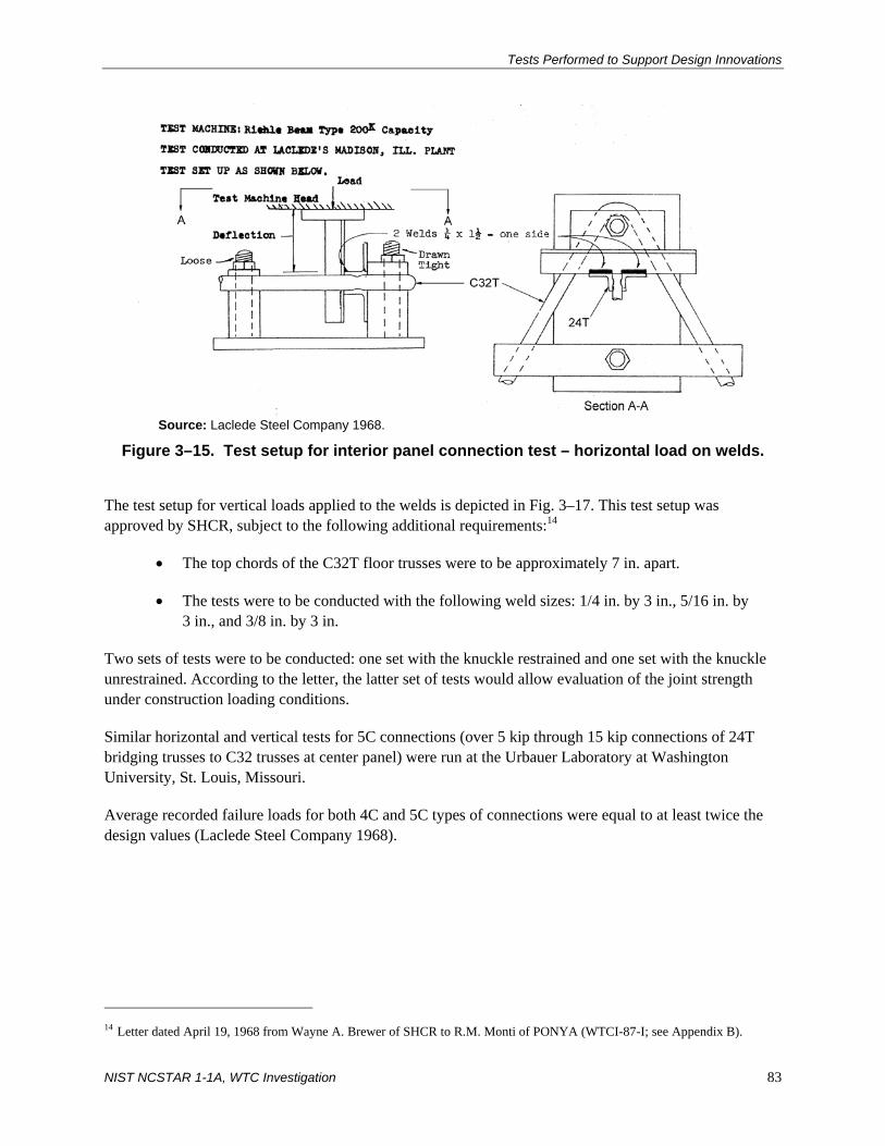
Tests Performed to Support Design Innovations
NIST NCSTAR 1-1A, WTC Investigation 83
Source: Laclede Steel Company 1968.
Figure 3–15. Test setup for interior panel connection test – horizontal load on welds.
The test setup for vertical loads applied to the welds is depicted in Fig. 3–17. This test setup was approved by SHCR, subject to the following additional requirements:14
• The top chords of the C32T floor trusses were to be approximately 7 in. apart.
• The tests were to be conducted with the following weld sizes: 1/4 in. by 3 in., 5/16 in. by 3 in., and 3/8 in. by 3 in.
Two sets of tests were to be conducted: one set with the knuckle restrained and one set with the knuckle unrestrained. According to the letter, the latter set of tests would allow evaluation of the joint strength under construction loading conditions.
Similar horizontal and vertical tests for 5C connections (over 5 kip through 15 kip connections of 24T bridging trusses to C32 trusses at center panel) were run at the Urbauer Laboratory at Washington University, St. Louis, Missouri.
Average recorded failure loads for both 4C and 5C types of connections were equal to at least twice the design values (Laclede Steel Company 1968).
14 Letter dated April 19, 1968 from Wayne A. Brewer of SHCR to R.M. Monti of PONYA (WTCI-87-I; see Appendix B).

Chapter 3
84 NIST NCSTAR 1-1A, WTC Investigation
Source: Laclede Steel Company 1968.
Figure 3–16. Results from interior panel connection tests – horizontal load on welds.
Source: Laclede Steel Company 1968.
Figure 3–17. Test setup for interior panel connection test – vertical load on welds.

Tests Performed to Support Design Innovations
NIST NCSTAR 1-1A, WTC Investigation 85
3.4.4 Bearing Capacity Tests
Two types of tests were performed to determine the bearing capacity at the ends of the floor trusses.15 The first set of tests was designed to determine the bearing strength of the as-designed floor trusses. The test setup for these tests is depicted in Fig. 3–18 and the test results are shown in Fig. 3–19 (see reference given in footnote number 15).
Source: Laclede Steel Company 1969.
Figure 3–18. Test setup for first set of bearing capacity tests on floor trusses.
15 Internal Laclede Steel Company memo dated March 18, 1969 from David B. Neptune to R.D. Bay (part of WTCI-82-I; see
Appendix B).

Chapter 3
86 NIST NCSTAR 1-1A, WTC Investigation
Source: Laclede Steel Company 1969.
Figure 3–19. Results from the first set of bearing capacity tests on floor trusses.
The following is a summary of the test results:
• Only one test resulted in a broken weld and this was at a load greater than the load that caused the initial bending of the angles.
• Using a 2 in. bearing length (Types A and B in Fig. 3–18) resulted in a “more critical loading condition” than using a 4 in. bearing length (Types C and D in Fig. 3–18). Deformation of the angles with a 2 in. bearing length occurred sooner than with a 4 in. bearing length.
• The weld failure load at the core end connection was found to be greater than that at the column end.
• Arc welding the bottom of the vertical strut decreases the possibility of a weld failure.
In all of the cases tested in the first set of tests, the ultimate load of the bearing capacity of the floor truss ends was shown to be greater than the design loads.
The purpose of the second set of tests was to determine the strength of repaired bearing ends that would be welded onto floor trusses at the jobsite. According to the report on these tests (Laclede Steel Company 1969), it was sometimes necessary to perform such modifications after the resistance welding was completed. Two types of tests were performed. The first type of test, which is depicted in “Figure 2-A” in Fig. 3–20, tested the capacity of the end as a unit (see reference given in footnote 15). In the second type of test, the strength of each joint in the bearing end was tested (see “Figure 2-B” in Fig. 3–20). The load capacities of the arc welded bearing ends obtained from these tests are shown in Fig. 3–21. The report concluded that the floor truss bearing ends, repaired in accordance with the procedure outlined in that report, were capable of carrying a load “substantially higher” than the design end reaction (Laclede Steel Company 1969).

Tests Performed to Support Design Innovations
NIST NCSTAR 1-1A, WTC Investigation 87
Source: Laclede Steel Company 1969.
Figure 3–20. Test setup for second set of bearing capacity tests on floor trusses.
Source: Laclede Steel Company 1969.
Figure 3–21. Results from the second set of bearing capacity tests on floor trusses.
Chapter 3
88 NIST NCSTAR 1-1A, WTC Investigation
3.5 STUD SHEAR CONNECTOR TESTS
A testing program was established to determine the horizontal shear capacity of 3/4 in. diameter by 4 1/2 in. long stud shear connectors welded through the troughs of Roll Form Type “B” steel deck and embedded in a lightweight concrete slab. These tests were needed, since, as noted in Sec. 2.3.4 of this report, the allowable shear load for such connectors in concrete with aggregates not conforming to ASTM International C 33 (i.e., the specification for normal weight aggregate) was to be established by a suitable testing program (AISC 1963). Requirements for the test program were outlined in a letter from SHCR to Bethlehem Fabricators.16 A work order was sent from the Port Authority to the Fritz Engineering Laboratory at Lehigh University to perform the tests on the specimens.17
It has not been possible to locate any results from this testing program.
3.6 REFERENCES
AISC (American Institute of Steel Construction). 1963. Specification for the Design, Fabrication, and Erection of Structural Steel for Buildings. New York, NY.
ASCE (American Society of Civil Engineers). 1961. Wind forces on structures–ASCE Final Report of Task Committee on Wind Forces. Transactions ASCE, vol. 126, Part II.
Crandall, S.H., and Wittig, L.E. 1969. Test of Viscoelastic Damping Units for World Trade Center Tower Buildings. (Box 9, 233 Park Avenue).
Gardner, N.J. 1966. Report on Tests on Models of the Structural Units of the World Trade Center. The University of Western Ontario. (part of WTCI-67-L).
Laclede Steel Company. 1968. Tests to Verify the Design Strength of Interior Panel Connections of 24T Bridging Trusses to C32 Trusses. (WTCI-68-I).
Laclede Steel Company. 1969. Report on Load Tests to Compare the Capacity of Normal Production Truss Bearing Ends with Trusses Having Repaired Bearing Ends. (WTCI-505-l).
PONYA (The Port of New York Authority). 1967. Fabricated Steel Floor Trusses, Bridging, Beams and Bracing for Prefabricated Floor Units for North and South Towers. World Trade Center Contract WTC-221.00 (WTCI-71-I).
Simiu, E., and Scanlon, R.H. 1996. Wind Effects on Structures – Fundamentals and Application to Design. Third Edition. John Wiley & Sons, Inc., New York, NY.
16 Letter dated November 3, 1969 from James White of SHCR to Lester S. Feld of PONYA (part of WTCI-253-L; see
Appendix B). 17 Contract dated January 6, 1970 from Guy F. Tozzoli of PONYA to Roger G. Slutter of the Fritz Engineering Laboratory,
Lehigh University (part of WTCI-253-L; see Appendix B).

Tests Performed to Support Design Innovations
NIST NCSTAR 1-1A, WTC Investigation 89
Whitbread, R.E. 1967. An Investigation of the Aerodynamic Stability of a Model of the Proposed Tower Blocks for the World Trade Center, New York, Part II – Further wind-tunnel studies relating mainly to the response of the tower blocks to turbulent winds. National Physical Laboratory. (part of WTCI-68-L).
Whitbread, R.E., and Scruton, C. 1965. An Investigation of the Aerodynamic Stability of a Model of the Proposed Tower Blocks for the World Trade Center, New York, Part I – An investigation of the amplitudes of oscillation in the fundamental mode for a range of wind conditions. National Physical Laboratory. (part of WTCI-271-L).
WSHJ (Worthington, Skilling, Helle, & Jackson). 1964. The World Trade Center – Wind Program Interim Report. December. (WTCI-559-L).
WSHJ (Worthington, Skilling, Helle, & Jackson). 1965a. The World Trade Center – Wind Program Interim Report, Supplement #3 with Appendix. June. (part of WTCI-68-L).
WSHJ (Worthington, Skilling, Helle, & Jackson). 1965b. The World Trade Center – Wind Program Interim Report, Supplement #1. January. (WTCI-561-L).
WSHJ (Worthington, Skilling, Helle, & Jackson). 1965c. The World Trade Center – Wind Program Interim Report, Supplement #2. 1965. (part of WTCI-68-L).
WSHJ (Worthington, Skilling, Helle, & Jackson). 1965d. The World Trade Center – Wind Program Interim Report, Supplement #4. January. (WTCI-558-L).
WSHJ (Worthington, Skilling, Helle, & Jackson). 1966a. Part III, Final Chapter, WSHJ Wind Report. July. (part of WTCI-68-L).
WSHJ (Worthington, Skilling, Helle, & Jackson). 1966b. Part II, Final Chapter, WSHJ Wind Report. July. (part of WTCI-68-L).
WSHJ (Worthington, Skilling, Helle, & Jackson). 1966c. Part I, Final Chapter, WSHJ Wind Report. June. (part of WTCI-68-L).

Chapter 3
90 NIST NCSTAR 1-1A, WTC Investigation
This page intentionally left blank.

NIST NCSTAR 1-1A, WTC Investigation 91
Chapter 4 PORT AUTHORITY POLICIES AND AGREEMENTS WITH NEW YORK CITY
DEPARTMENT OF BUILDINGS
A memorandum of understanding between the Port Authority of New York and New Jersey (Port Authority or PANYNJ) and the New York City Department of Buildings was established in 1993.1 Even though it was a “long-standing policy” of the Port Authority that its facilities meet or exceed New York City Building Code requirements, the purpose of this document was to formally restate that policy. Specific commitments were made by the Port Authority to the Buildings Department that would ensure that any building construction project undertaken by the Port Authority or by any of its tenants at the buildings owned and operated by the Port Authority that were located within the Department of Buildings’ jurisdiction would conform to the New York City Building Code.
A summary of this agreement follows:
• The Port Authority was to thoroughly review and examine all plans for conformance with the requirements of the then current New York City Building Code. Such reviews were to be conducted by New York State licensed professional engineers or architects retained or employed by the Port Authority. Plans for projects undertaken by Port Authority tenants were to be prepared and sealed by a New York State licensed professional engineer or architect retained or employed by the tenant. Similarly, for projects undertaken by the Port Authority, plans were to be prepared and sealed by a New York State licensed professional engineer or architect retained or employed by the Port Authority.
• The Port Authority was to maintain a file containing the most recent drawings, plans, and other documents required in connection with the review of the project for code conformance.
• The Port Authority was required to obtain the certification of a New York State licensed professional engineer or architect that any tenant project undertaken at any of its facilities was constructed in accordance with the approved plans and specifications for the project. Such certification was to be kept in the project file described above.
• The Port Authority was required to provide copies of any project files to the Department of Buildings at any time.
• The Port Authority was to promptly advise the Department of Buildings of any variances from code requirements that were proposed on a project. In cases where the Department of Buildings believed that such variances were unacceptable, further review by the Port Authority Board of Commissioners was required.
1 Memorandum of Understanding Between the New York City Department of Buildings and the PANYNJ, 1993 (WTCI-160-P;
see Appendix C).

Chapter 4
92 NIST NCSTAR 1-1A, WTC Investigation
• The Port Authority was required to perform building inspections and structural integrity inspections on a cyclical basis for all of its structures located in New York City.
• The Port Authority was responsible for life safety in buildings at its facilities. The Department of Buildings was not responsible for any type of inspection or review.
• Personnel from the Port Authority and the Department of Buildings were not to be held personally responsible under any provision of this agreement.
A supplement to this agreement was executed in 1995.2 The supplement added that the design professional responsible for performing the review and certification of plans for World Trade Center tenants must not be the same design professional providing certification that the project had been constructed in accordance with the plans and specifications.
2 Supplement to Memorandum of Understanding Between the New York City Department of Buildings and the PANYNJ, 1995
(WTCI-113-P; see Appendix C).

NIST NCSTAR 1-1A, WTC Investigation 93
Chapter 5 INNOVATIVE SYSTEMS, TECHNOLOGIES AND MATERIALS, AND ACCEPTANCE PROCEDURES USED BY THE PORT AUTHORITY
5.1 INNOVATIVE FEATURES OF THE STRUCTURAL SYSTEM
The structural system, comprising the lateral-force-resisting as well as the gravity-load-carrying systems, of World Trade Center (WTC) 1 and WTC 2 towers incorporated several innovative features including the following:
1. The towers represented one of the earliest applications of the framed-tube lateral-force-resisting system to super high-rise buildings (see Sec. 5.2).
2. Uniform perimeter column geometry (14 in. by 14 in. cross-section) was maintained over most of the height of the 110-story buildings.
3. Fourteen different specified grades of steel were used to allow the perimeter column geometry to remain uniform throughout the heights of the buildings.
4. Deep spandrel plates were used as beam elements connecting perimeter columns, enabling framed tube action by strapping around the structure.
5. Prefabrication of steel construction was extensively used, through using 3-column-wide by 3-stories-high panels, bolted butt-plate column splices, and high-strength bolted shear connections of the spandrel plates.
6. Specially designed corner panels with chamfered edges were used to facilitate force transfer around the corners of the framed-tubes.
7. Long-span floor trusses were used for the floor systems. Composite action was achieved between the floor trusses and the concrete floor slab by extending the truss diagonals above the top chord into the slab. The concrete floor slab acted as a rigid diaphragm, which distributed the lateral forces to the elements of the tube according to their stiffnesses.
8. Viscoelastic dampers connecting the floor trusses to the perimeter framed tube system were used in each tower to control dynamic response, as discussed in Sec. 5.4.
9. Extensive wind tunnel testing was performed to establish the lateral wind loads used in the design of the towers.
It is important to note that except for Items 7 and 8 above, the innovative features were not appraised by acceptance procedures. Such procedures for Items 7 and 8 are discussed in Secs. 5.3 and 5.4, respectively. Tests to support the design innovations were done for Items 5, 7, 8, and 9.

Chapter 5
94 NIST NCSTAR 1-1A, WTC Investigation
5.2 LATERAL-FORCE-RESISTING SYSTEM OF WTC 1 AND WTC 2
The exterior walls of WTC 1 and WTC 2, comprised of steel columns and spandrel plates, were designed to resist the lateral forces and a portion of the gravity forces. Above the 7th floor, the columns were welded steel plate box columns, spaced 3 ft 4 in. on center. The columns and spandrels were shop-assembled and welded into 36 ft high by 10 ft wide panels, which consisted of three columns and three spandrels as shown in Fig. 5–1 (WSHJ 1967a). These panels were erected on site by bolting the base plate of an upper column to a cap plate of a lower column. Such splices were staggered so that only one-third of the panels were spliced at each story level, except at the base of the building and at the mechanical floors where all of the panels were spliced at the same level. In such cases, supplemental welds were employed to improve connection capacity. Spandrels were connected at midspan with high-strength bolted shear connections.
Source: WSHJ 1967a. Reproduced with permission of The Port Authority of New York and New Jersey.
Figure 5–1. Exterior wall panels in WTC 1 and WTC 2.
A A
12′-0
″ Column
Spandrel
Section A-A

Innovative Systems, Technologies, Materials, and Accept. Proc.
NIST NCSTAR 1-1A, WTC Investigation 95
Below the 7th floor, the columns were typically spaced 10 ft 0 in. apart. The transition from three columns to one column occurred just below the 7th floor level as illustrated in Fig. 5–2.1 Below the 7th floor, where there were fewer perimeter columns, bracing was used in the core area to increase lateral stiffness, and the core columns were designed to resist a portion of the lateral forces.
Source: WSHJ 1967b. Reproduced with permission of The Port Authority of New York and New Jersey.
Figure 5–2. Exterior wall panel transition in WTC 1 and WTC 2.
This structural system is considered to be a framed-tube system (closely spaced columns and deep spandrel members) (Khan 1983). In such systems, the frames parallel to the applied lateral forces act as the webs of the tube and resist the shear from the lateral forces through bending of the beams and columns in the frames. The floor system is considered a rigid diaphragm and is typically assumed to distribute the lateral forces to the elements of the tube according to their stiffness (although in the case of WTC 1 and WTC 2, no evidence was found from the calculations that diaphragm action was explicitly
1 Structural drawing 2-AB2-2 (WSHJ 1967b).

Chapter 5
96 NIST NCSTAR 1-1A, WTC Investigation
considered in the design). Portions of the normal frames close to the corners of the tube act as flanges of the parallel frames. When subjected to lateral forces, the columns in the windward wall (flange) are subjected to tensile forces, while those on the leeward wall (flange) are subjected to compressive forces. Framed-tube systems do not behave as a true cantilever when subjected to lateral forces. The flexibility of the spandrel beams produces a shear lag that increases the axial forces in the corner columns and reduces the axial forces in the inner columns of both the flanges and the webs. A representative structural framing plan of a typical floor in WTC 1 or WTC 2 is shown in Fig. 5–3.
Source: Reproduced with permission of The Port Authority of New York and New Jersey.
Figure 5–3. Representative structural framing plan on a typical floor of WTC 1 or WTC 2.
WTC 1 and WTC 2 are early examples of super high-rise buildings that were designed based on the framed-tube concept. The first application of a framed-tube system was the 43-story DeWitt-Chestnut apartment building (later renamed The Plaza on DeWitt) in Chicago, which was completed in 1965. Designed by Skidmore, Owings & Merrill, this 395 ft tall building used reinforced concrete for the

Innovative Systems, Technologies, Materials, and Accept. Proc.
NIST NCSTAR 1-1A, WTC Investigation 97
structural framing system. Since then, many variations of this structural system were used in a number of buildings, which were constructed between the mid-1960s through the early 1970s. A number of major buildings that have incorporated the framed-tube concepts in the United States include:
• Brunswick Building, Chicago, Illinois. Completed in 1965, this 38 story, 550 ft tall reinforced concrete office building designed by Fazlur Khan of Skidmore, Owings & Merrill utilizes a tube-in-tube system. In this system, the shear walls in the core area form an inner tube and the closely spaced columns with deep spandrel beams at the perimeter of the building form the outer tube.
• John Hancock Center, Chicago, Illinois. Diagonal braces supplement the steel framed-tube system in this 100-story, 1,127 ft tall mixed-use building, which was completed in 1969. Skidmore, Owings & Merrill designed this building as well.
• One Shell Plaza, Houston, Texas. Skidmore, Owings & Merrill, also designed this 50 story, 714 ft tall building. Completed in 1971, it uses a tube-in-tube structural system of reinforced concrete.
• Aon Center, Chicago, Illinois. At 1,136 ft tall, this 83-story steel office building, which was formerly known as the Amoco Building and before that as the Standard Oil Building, was completed in 1973. This steel office building utilizes a framed-tube system. Perkins & Will was the structural engineer for this project.
• Sears Tower, Chicago, Illinois. A bundled tube system is used in this 108-story, 1,450 ft tall steel building designed by Skidmore, Owings & Merrill, which as completed in 1974. A series of tubes are interconnected to form the lateral-force-resisting system. In this system, wider column spacing than would be possible for only an exterior framed-tube was used.
5.3 DAMPING UNITS
5.3.1 Overview
Viscoelastic damping units were part of the structural system in WTC 1 and WTC 2 to supplement the tubular steel frame in limiting wind-induced building oscillations to levels below human perception. According to Mahmoodi (1987), “The selection, quantity, shape, and location of the dampers was based on the dynamic analysis of the towers (computer modeling, wind tunnel, etc.), and of the damping required to achieve performance standards.” This may have been the first application of damping units for this purpose in tall building structures, and would certainly qualify it as an innovative system at that time.
The damping units were uniformly distributed throughout both of the buildings. Approximately 100 were used on each floor from the 7th to the 107th floor. The exact number and planned locations of damping units on the various floors of the buildings are contained in structural drawings D-AB1-2 through D-AB1-14.2 (WSHJ 1967b). As the buildings oscillated from the wind, part of the energy of oscillation was dissipated by shear deformations in the viscoelastic part of the damping units.
Two different types of damping units were used in WTC 1 and WTC 2. Type A damping units were used on floors with trusses spanning between the core and the outside wall, and were located between the

Chapter 5
98 NIST NCSTAR 1-1A, WTC Investigation
bottom chords of the floor trusses and the columns of the outside wall (Fig. 5–4). Type B damping units were used on floors that had wide-flange beams spanning between the core and the outside walls (i.e., floors 7, 9, 41, 43, 75, 77, and 107). This type of damping unit was located between the bottom flanges of the floor beams and the outside wall, as shown in Fig. 5–5. The details of a damping unit are illustrated in Fig. 5–6.
Source: McAllister 2002.
Figure 5–4. Floor truss member with Type A damping units.
Damping unit extension

Innovative Systems, Technologies, Materials, and Accept. Proc.
NIST NCSTAR 1-1A, WTC Investigation 99
Source: WSHJ 1967b. Reproduced with permission of The Port Authority of New York and New Jersey.
Figure 5–5. Wide-flange beam floor member with Type B damping units.
Type B damping units were slightly longer than Type A damping units. Also, the connections between Type A damping units and the floor trusses were different than those between Type B damping units and the wide-flange beams. Sheet DA-3 in the structural drawings shows specific details for each type of damping unit (WSHJ 1967b).
Worthington, Skilling, Helle & Jackson (WSHJ) initially inquired about different types of viscoelastic damping materials in a letter to Minnesota Mining and Manufacturing Company (3M) in 1964.2 A follow-up letter from them to 3M contained the physical and mechanical properties required for the viscoelastic material, based on calculations they had performed.3 Additional correspondence on various aspects of the damping units, including the results of tests that were run at 3M that measured the properties of the damper material and the strength of an assembled damping unit prototype, was exchanged subsequent to these letters.4 In particular, it was noted that testing of an assembled truss damping unit by 3M was completed and that the results agreed with the theoretical predictions.5
2 Letter dated July 16, 1964 from Alan G. Davenport of WSHJ to Carl A. Dahlquist of 3M (WTCI-450-L; see Appendix D). 3 Letter dated November 23, 1964 from Richard D. Steyert of WSHJ to Carl A. Dahlquist of 3M (WTCI-450-L; see
Appendix D). 4 Various memos and letters in WTCI-450-L. 5 Internal correspondence dated February 1966 by Richard D. Steyert of WSHJ (WTCI-450-L; see Appendix D).

Chapter 5
100 NIST NCSTAR 1-1A, WTC Investigation
Source: WSHJ 1967c. Reproduced with permission of The Port Authority of New York and New Jersey.
Figure 5–6. Damping unit details – Types A and B.
5.3.2 Specifications
A draft specification for the damping units was written by WSHJ in mid-19666, and comments and additions to the specification were supplied by 3M to WSHJ in late October of that year.7
In addition to the specifications, Skilling, Helle, Christiansen, & Roberton (SHCR) proposed to Port of New York Authority (PONYA) in 1967 a prototype test program for the damping units.8 The report that was submitted to PONYA states the uniqueness of the proposed damping system and points out the value of having independent testing (i.e., tests in addition to those performed by 3M) to measure the performance of the damping units.
6 Undated internal memo by R. Taylor of WSHJ. Includes draft of specification (WTCI-450-L). 7 Letter dated October 31, 1966 from Don Caldwell of 3M to James White of WSHJ (WTCI-501-L; see Appendix D). 8 Letter dated October 30, 1967 and enclosure from Leslie E. Robertson of SHCR to John H. Kyle (Chief Engineer), PONYA
(WTCI-501-L; see Appendix D).
10″
0.05″ × 4″ × 10″
¼″ bolts

Innovative Systems, Technologies, Materials, and Accept. Proc.
NIST NCSTAR 1-1A, WTC Investigation 101
Included in the report were the test parameters that were needed for evaluating the effectiveness of the damping units, which included dynamic stiffness, loss factor, and temperature changes. These parameters are defined in Fig. 5–7. The hysteresis loop that is shown in this figure represents the results obtained from the tests that were performed on the damping units (see Sec. 3.3 of this report for a description of these tests).
Source: Reproduced with permission of The Port Authority of New York and New Jersey.
Figure 5–7. Parameters related to mechanical properties of damping units.

Chapter 5
102 NIST NCSTAR 1-1A, WTC Investigation
The draft contract between 3M and PONYA, dated November 1, 1968, contained the technical specifications for the damping units (Appendix A of the contract).9 In general, these specifications covered the manufacture and testing of the units. SHCR supplied comments on the draft contract to the PONYA.10 Other adjustments were subsequently made to the specifications, and the final draft of the specifications was issued on November 6, 1969.11
The specifications were to prevail in the event that there was a conflict between any requirements in the specifications and the requirements on the contract drawings (Sec. 0.01 in the contract). No existing standards (such as ASTM International) covered the damping units that were used in this project. Damping units were accepted or rejected based on the requirements given in the specifications.
According to Sec. 21 of the contract, 3M was to conform to all orders, directions, and requirements of the Chief of the Planning and Construction Division of the World Trade Center of the World Trade Department of PONYA (referred hereafter, as in the contract, as the “Engineer”), and was to perform the requirements in the contract to the satisfaction of that person. The Engineer also had the power to alter the contract drawings and specifications.
The following is a summary of the requirements in Chapters 1 and 2 of the November 6, 1969 edition of the technical specifications. Unless otherwise noted, referenced section numbers are from the contract (PONYA 1969).
Chapter 1 – General Conditions
The materials and workmanship that went into the damping units were to conform to “the best modern practice” (Sec. 0.02). If the contract drawings, specifications, or directions of the Engineer left any doubt as to what was permissible or failed to note the quality of any construction, the interpretation that called for the best quality of construction was to be followed. Any errors or discrepancies in the contract drawings or specifications were to be reported to the Engineer as soon as possible (Sec. 0.04).
According to Sec. 0.06, Inspections, testing and storage operations were subject to inspection at any time by the Engineer or by inspectors acting as agents of the Engineer. 3M was required to give the Engineer at least 10 days notice prior to any testing required in accordance with the specifications.
The contract drawings were considered part of the specification (Sec. 0.08). Revised drawings of the structural tees (DA-1), structural bars (DA-2), and viscoelastic damping units (DA-3) were finalized on May 21, 1970. These drawings did not show all of the details of the components that made up the damping units, and were intended only to illustrate the character and extent of such units.
The responsibilities of 3M with respect to this contract are outlined in Sec. 0.09. They were responsible for (1) machining the structural tees and bars that were to be supplied by others, (2) applying the protective aprons to the viscoelastic material, bonding adhesives, and viscoelastic materials to the tee flange face and both sides of the bar, (3) assembling two tees and one bar into a damping unit, (4) shipping and bundling the completed units according to type (Type A or B), and (5) testing the units 9 Draft contract WTC-224.00 for damper units dated November 1, 1968 between PONYA and 3M (WTCI-500-L). 10 Letter dated April 4, 1969 from Leslie Robertson of SHCR to Malcolm P. Levy of PONYA (WTCI-501-L; see Appendix D). 11 “Specification for Viscoelastic Damping Units” dated November 6, 1969 (PONYA 1969) (WTCI-501-L; see Appendix D).

Innovative Systems, Technologies, Materials, and Accept. Proc.
NIST NCSTAR 1-1A, WTC Investigation 103
in accordance with the requirements contained in the contract. 3M was not responsible for furnishing the structural tees or bars, painting the damping units, or installing them in the towers. Installation instructions were contained on structural drawing D-AB1-1.3 (WSHJ 1967b).
The structural tees and bars were fabricated from steel conforming to ASTM A 36-63T or ASTM A 572, Grade 42 (Sec. 0.10). Fabrication tolerances were to conform to the AISC Specifications for the Design, Fabrication, and Erection of Structural Steel for Buildings dated April 17, 1963 (AISC 1963), and to the requirements contained in the contract drawings and paragraphs C, D, and E in Sec. 0.10 of the specifications. Sections C and D contained the special requirements for the structural tees and structural bars, respectively. Section E required that certification be provided for all components that were supplied by others.
Chapter 2 – Technical Requirements
Approved materials to be used in the manufacture of the damping units are contained in Sec. 2.0 of the specifications and are summarized in Table 5–1 (PONYA 1969). The shop drawings for the structural steel tees and bars that were used in the damping units were considered to be part of the material specifications, even though 3M was not responsible for the manufacture of these members.
Table 5–1. Material specifications for damping units per WTC Contract WTC-224.0.a Material Specification
Viscoelastic material 3M Brand Vibration Damping Elastomer, #Y-9274b Steel ASTM A 36-63T or ASTM A 572 Grade 42 Assembly bolts 1/4 in. diameter bolts conforming to ASTM A 307 Standard
Specification for Low-Carbon Steel Externally and Internally Threaded Standard Fasteners
Bonding adhesive 3M Scotchweld Brand Structural Adhesives EC 1614 and 3520
Protective aprons 3M Scotch Brand Pressure Sensitive Tape #465 a. Shop drawings for structural tees and bars were considered to be part of the material specifications. b. Other viscoelastic materials could be used subject to approval of PONYA. Request for approval
was to be accompanied by full technical data on the material including documentation of performance characteristics of the damping unit proposed for the work.
Quality Assurance Program— Section 5.0 contains the quality assurance program that was created for the damping units. This program included requirements for both initial and long-term (5 year) acceptance. It also included the test methods that were to be used to determine whether damping units met these requirements. A brief summary of each of the elements that made up the quality assurance program is given below.
• Acceptance. A lot of dampers would be deemed acceptable by PONYA after sampled dampers from that lot were tested in accordance with the procedures in Sec. 5.3 of the technical specification and were shown to meet the requirements in Sec. 4.1. An acceptance lot consisted of all dampers made in each calendar week from the same lot of viscoelastic material by the same process and submitted for acceptance testing at one time.

Chapter 5
104 NIST NCSTAR 1-1A, WTC Investigation
The acceptance requirements of Sec. 4.1 are summarized in Table 5–2 (PONYA 1969). Detailed test procedures for loss factor and stiffness, fatigue strength, and ultimate strength are given in Secs. 5.3.6.1, 5.3.6.2, and 5.3.6.3 of the technical specification, respectively. Methods on how to select a sample size for loss factor, stiffness, and fatigue tests are given in Sec. 5.1.3.1. Sample size for ultimate strength tests are provided in Sec. 5.1.3.2. In short, a single lot of dampers is accepted if the predetermined sample meets all of the criteria contained in Table 5–2.
Sampled dampers in an accepted lot that were not damaged during testing were to be delivered to PONYA. All dampers were to be labeled in accordance with the identification codes in Sec. 5.1.4. Dampers that were subjected to acceptance testing were labeled differently from those that were not subjected to testing.
Table 5–2. Acceptance requirements for damping units per WTC Contract WTC-224.0.
Item (units)a
Number of Dampers in
Sample Acceptance Requirementb 5 Requirement average = 0.7 + 0.948σi
c 10 Requirement average = 0.7 + 0.670σi
Loss Factor (dimensionless)
15 Requirement average = 0.7 + 0.547σi 5
10 Stiffness (lb)
15 6,000 + 1.25σi < Requirement average < 20,000 – 1.25σi
Ultimate Strength (lb)
5 For an individual damper, ultimate strength > 40,000 lb at 75° F If 0 or 1 damper fails, the lot is accepted. If 2 fail, take a second sample of 5 dampers. All must pass.
5 10
Fatigue (lb)
15 5,400 + 1.25σi < Requirement average < 22,000 – 1.25σi
a. See Fig. 5–5 for definition of terms. b. Requirement average = limiting average value of the specified parameter determined from a given sample as set forth in
the equations for each parameter. c. σi = standard deviation computed from Eq. 3–1 or Eq. 3–2 in Sec. 3.2.
• Five-Year Testing. Unused (or virgin) dampers were also to be tested not less than 5 years nor more than 5 years and 3 months after all the dampers in a given 5 year lot were manufactured. In short, a number of dampers were to be set aside and tested within the time frame described above to determine whether any changes had occurred in stiffness, loss factor, or ultimate strength. Unlike in the acceptance requirements, fatigue tests were not required for the damping units in the 5 year lots.
Damping units to be used in the 5 year tests were to be stored by 3M in conformance with the conditions outlined in Sec. 5.3 of the specifications.

Innovative Systems, Technologies, Materials, and Accept. Proc.
NIST NCSTAR 1-1A, WTC Investigation 105
After the samples from a 5 year lot were tested in accordance with Sec. 5.3 and the requirements in Sec. 4.2 were met, the lot was deemed to have passed the 5 year test. The requirements of Sec. 4.2 of the specifications are summarized in Table 5–3 (PONYA 1969).
Table 5–3. Five-year acceptance requirements for damping units per WTC Contract WTC-224.0.
Item (units)a
Number of Dampers in
Sample Acceptance Requirementb 10 Requirement average = 0.63 + 0.948σi
c 20 Requirement average = 0.63 + 0.670σi
Loss Factor (dimensionless)
30 Requirement average = 0.63 + 0.547σi 10 20
Stiffness (lb)
30 5,400 + 1.25σi < Requirement average < 22,000 – 1.25σi
Ultimate Strength (lb)
13 For an individual damper, ultimate strength > 36,000 lb at 75° F If 0, 1, 2, or 3 damper fail, the lot is accepted. If 4 fail, take a second sample of 13 dampers. All must pass.
a. See Fig. 5–5 for definition of terms. b. Requirement average = limiting average value of the specified parameter determined from a given sample as set forth in
the equations for each parameter. c. σi = standard deviation computed from Eq. 3–1 or Eq. 3–2 in Sec. 3.2.
A 5 year lot was one-fourth of the total number of dampers specified in the contract (Sec. 5.2.2). The number of dampers that were to be tested for loss factor and stiffness was determined in accordance with Sec. 5.2.3.1, while Sec. 5.2.3.2 of the contract contained the number of dampers that were to be tested for ultimate strength.
Similar to the acceptance testing, sampled dampers in an accepted lot that were not damaged during testing were to be delivered to PONYA. Dampers subjected to 5 year tests were to be labeled in accordance with the requirements in Sec. 5.2.4.
5.4 FLOOR TRUSSES
5.4.1 Overview
Outside of the central core area, floor construction of WTC 1 and WTC 2 typically consisted of 4 in. of lightweight concrete on 1 1/2 in., 22-gauge fluted metal deck supported by a series of composite floor trusses that spanned between the core and the exterior walls (see Fig. 5–8). A pair of main floor trusses, spaced 6 ft 8 in. apart on center, spanned either approximately 60 ft or 35 ft from the core to the exterior walls, where they were supported on every other column. At the core, floor trusses were supported on channels that were supported by the core columns. The metal deck spanned parallel to the main floor trusses and was supported on transverse (bridging) floor trusses that were spaced at 13 ft 4 in. on center and on deck support angles that were spaced at 6 ft 8 in. on center from the transverse (bridging) floor trusses. Pairs of flat bars (straps) extended diagonally from the top chord of the floor trusses to the perimeter columns (see Fig. 5–3). Figure 5–8 shows a typical 20 ft by 60 ft prefabricated floor unit that was used in the towers (PONYA 1967). As shown in this figure, the floor trusses consisted of double

Chapter 5
106 NIST NCSTAR 1-1A, WTC Investigation
angles that were used for the top and bottom chords and round bars that were used for the diagonals. A section through the main double trusses is shown in Fig. 5–9.
What made the floor system in WTC 1 and WTC 2 innovative from a structural standpoint was the way that composite action was achieved between the floor trusses and the concrete slab. Truss diagonals were extended above the top chord, as shown in Figs. 5–4 and 5–8. This “knuckle” acted like a shear stud, which made the floor truss and concrete slab act in a composite manner.
Source: PONYA 1967. Reproduced with permission of The Port Authority of New York and New Jersey.
Figure 5–8. Prefabricated floor unit used in WTC 1 and WTC 2.

Innovative Systems, Technologies, Materials, and Accept. Proc.
NIST NCSTAR 1-1A, WTC Investigation 107
Source: PONYA 1967. Reproduced with permission of The Port Authority of New York and New Jersey.
Figure 5–9. Section through the main double trusses in the floor system of WTC 1 and WTC 2.
The first recorded tests on composite open-web steel joists were conducted under a project jointly sponsored by Granco Steel Products and Laclede Steel Company (who manufactured the trusses for WTC 1 and WTC 2) in September of 1964.12 In this study, the overall performance of non-composite joists was compared with composite joists. The joists were manufactured with their webs projecting above the top chord. The tests revealed that the composite joists had greater moment capacities and smaller deflections than the non-composite joists.
Additional tests on open-web joists were performed at Washington University (Tide and Galambos 1968). The findings, which were reported in February of 1968, were similar to those reported from the previous tests. In particular, the specimens with extended web diagonals into the concrete slab serving as shear connectors were shown to be strong and stiff, and failure was due to crushing of the concrete near the connectors. Further tests conducted at Washington University are reported in Sen and Galambos (1968). In summary, the findings from this study confirmed those obtained from earlier research programs that are summarized in that report.
The composite floor trusses used in the WTC towers were similar to those that were tested only in the sense that the webs were used as shear connectors. Other than that, they were different in all other aspects, including member sizes and overall lengths. It may have been the first time that this type of floor construction was used in a high-rise building, especially of this size.
12 See Sec. 1.1 of Sen and Galambos (1968).

Chapter 5
108 NIST NCSTAR 1-1A, WTC Investigation
5.4.2 Specifications
The contract between the Laclede Steel Company and PONYA, dated October 1967, contained the technical specifications for the trusses (PONYA 1967). The floor trusses, bridging, beams, and bracing supplied by Laclede were to conform to these specifications, and according to Sec. 15 of the contract, PONYA was to inspect these members at Laclede’s plant prior to shipment.
According to Sec. 19 of the contract, Laclede was to conform to all orders, directions, and requirements of the Chief of the Planning and Construction Division of the WTC of the World Trade Department of PONYA (referred hereafter, as in the contract, as the “Engineer”), and was to perform the requirements in the contract to the satisfaction of that person. The Engineer also had the power to alter the contract drawings and specifications.
The following is a summary of the requirements in the technical specifications. Unless otherwise noted, referenced section numbers are from the contract (PONYA 1967).
Chapter 0 – General Requirements
The specifications were to prevail in the event that there was a conflict between any requirements in the specifications and the requirements on the contract drawings (Sec. 0.001).
The materials and workmanship that went into the floor trusses and other supplied members were to conform to “the best modern practice” (Sec. 0.003). If the contract drawings, specifications, or directions of the Engineer left any doubt as to what was permissible or failed to note the quality of any construction, the interpretation that called for the best quality of construction was to be followed. Any errors or discrepancies in the contract drawings or specifications were to be reported to the Engineer as soon as possible (Sec. 0.005).
According to Sec. 0.006, Laclede was to comply with all provisions of federal, state, municipal, local, and departmental laws, ordinances, rules, regulations, and orders that would affect the contract.
The contract drawings, as well as the structural details and design sheets, were considered part of the specification (Sec. 0.009).
As a substitute for the design shown in the contract drawings (Sec. 0.009B), which can also be found in Laclede Steel Company (1967), Laclede was allowed to detail and fabricate the floor members in accordance with the design criteria prepared by WSHJ in 1965 (WSHJ 1965) (Sec. 0.009A). These criteria were appended to the contract.
Items to be included and excluded from the contract are contained in Sec. 0.010. Laclede was responsible for the following items:
• Floor trusses
• Bridging trusses
• Transverse beams or angles to support steel deck and power/telephone cells or angles

Innovative Systems, Technologies, Materials, and Accept. Proc.
NIST NCSTAR 1-1A, WTC Investigation 109
• Horizontal wind bracing at exterior end of prefabricated floor unit
• Closure strips at top chord of floor trusses and bridging trusses
• Clips and patch plates required by the steel erector to assemble individual components into prefabricated panels
• End bearing connection material for floor truss seats at the exterior column and the core end of the floor trusses
• Connection material at the exterior end for damping units.
Field bolts, assembly of the floor trusses, connections, damping units, and welding electrodes were excluded from the contract.
Chapter 1 – General Provisions
The codes, standards, and specifications cited in the specification are contained in Sec. 101.300. Where specific dates are not cited, the latest edition or revision as of September 1, 1966 was to be used in accordance with Sec. 101.100. Where codes, standards, and specifications given in Sec. 101.300 cite other codes, standards, or specifications, the edition or revision cited shall be used (Sec. 101.200). In cases where specific editions or revisions are not cited, the Engineer had final say over the appropriate edition or revision to use.
The following codes and specifications are listed in Sec. 101.300:
• Specification for the Design, Fabrication and Erection of Structural Steel for Buildings, American Institute of Steel Construction, April 1963 (AISC 1963).
• Code of Standard Practice for Steel Buildings and Bridges, American Institute of Steel Construction, February 1963.
• Code for Welding in Building Construction, D1.0-66, American Welding Society, 1966.
• Specifications for Welded Highway and Railway Bridges, D2.0-66, American Welding Society, 1966 (only where specifically noted in the drawings).
• Standard Specifications for Open Web Steel Joists and Longspan Steel Joists, Steel Joist Institute and the American Institute of Steel Construction, 1965.
Requirements for the shop drawings are also contained in this chapter of the specifications.
Quality control and inspection requirements are given in Sec. 105. All fabrication and welding of the floor trusses was subject to continual visual inspection, surveillance, and supervision by qualified personnel of Laclede. Details of this quality control plan, which included full-scale load tests on completely fabricated truss components, are given in Chapter 6 of this report.

Chapter 5
110 NIST NCSTAR 1-1A, WTC Investigation
Chapter 2 – Materials
Steels conforming to the specifications listed in Sec. 201 were approved to be used in the manufacture of the floor trusses. Steels conforming to the ASTM grades A302, A441, A514, and A533 with the specific modifications listed in Sec. 202.100 were also allowed, as were the proprietary grades listed in Sec. 203 with the approval of the Engineer.
Specifications for bolts, welding materials, and structural steel pipe are contained in Secs. 204, 205, and 206, respectively.
Chapter 3 – Fabrication of Structural Steel
Structural steel was to be fabricated as shown in the contract drawings. Fabrication tolerances were to conform to the requirements of the American Institute of Steel Construction (AISC) Specification and American Welding Society (AWS) D1.0 as well as to the requirements in Sec. 304.100. Additional details on the fabrication requirements are contained in Sec. 6.3.1 of this report.
Chapter 4 – Welding of Structural Steel
According to Sec. 401.100, welding was to conform to the requirements of the AISC Specification and AWS D1.0, except where the requirements in these documents were modified or supplemented by information in the contract drawings or the specification.
Welders and welding operators had to pass the applicable AWS qualification tests prescribed in AWS D1.0, Appendix D, Parts II and III. Such tests were to be supervised and witnessed by an outside agency approved by the Engineer. This agency would issue certification papers for the welders based on the results of the tests.
Specific requirements for the welding operations are contained in Secs. 403, 404, and 405.
Chapter 5 – Bolted Structural Joints
All bolts and washers for applicable structural joints were to conform to ASTM A325, except in locations where ASTM A307 or ASTM A490 bolts and washers were specifically called for in the structural drawings (Sec. 501.100).
High-strength bolts and washers were to be installed in conformance with Specifications for Structural Joints Using ASTM A325 or A490 Bolts, Research Council on Riveted and Bolted Joints of the Engineering Foundation, 1966.
Chapter 6 – Painting
According to Sec. 601.100, all floor trusses, bridging angles, and incidental structural items in the floor system were to receive a uniform shop coat of protective paint applied within one year or less of the delivery date in accordance to the requirements in this chapter. The protective paint was to be applied by the electro-phoresces process involving a direct current through a deionized water paint bath, which was

Innovative Systems, Technologies, Materials, and Accept. Proc.
NIST NCSTAR 1-1A, WTC Investigation 111
to provide an average dry film of 1 mil thickness. Chord angles for trusses were to be cleaned by shot blasting prior to painting (Sec. 602.100).
The shop paint was to be in accordance with Pittsburgh Plate Glass (PPG) Company Standard RF-2184 initial tank charging material with PPG red power primer RF-2184 replenishing material or Laclede Standard Red Chromate Steel Primer, Specification LREP 10001. The red shop paint was to withstand 150 hours of 5 percent salt fog (equivalent to a normal exposure of 18 months) when applied to a clean rolled steel panel at 1 mil dry film thickness. It was to be tested in accordance to ASTM B 117-64 Salt Fog Test, and the maximum failure allowed was to be in accordance with ASTM D 714-56. Other requirements for the painting system and painting of erection marks are contained in Secs. 604 and 605, respectively.
5.5 REFERENCES
AISC (American Institute of Steel Construction). 1963. Specification for the Design, Fabrication, and Erection of Structural Steel for Buildings. New York, NY.
Khan, F.R. et. al. 1983. Developments in Tall Buildings 1983. Council on Tall Buildings and Urban Habitat. Hutchinson Ross Publishing Company. Stroudsburg, PA.
Laclede Steel Company. 1967. World Trade Center Floor Grid Trusses Basic Design Data. Structural Calculations. February. (WTCI-75-I).
Mahmoodi, P. et. al. 1987. Performance of Viscoelastic Dampers in World Trade Center Towers. ASCE Conference. Orlando, FL. (WTCI-231-W&C).
McAllister, T., ed. 2002. World Trade Center Building Performance Study: Data Collection, Preliminary Observations, and Recommendations. FEMA 403. Federal Emergency Management Agency. Washington, DC, May.
PONYA (Port of New York Authority). 1967. Fabricated Steel Floor Trusses, Bridging, Beams and Bracing for Prefabricated Floor Units for North and South Towers. World Trade Center Contract WTC-221.00. (WTCI-71-I).
PONYA (Port of New York Authority). 1969. Viscoelastic Damping Units for North and South Towers. World Trade Center Contract WTC-224.00. (WTCI-501-L).
Sen, S.K. and Galambos, T.V. 1968. Composite Open Web Steel Joists with Extended Webs. Research Report No. 8, Structural Division, Civil and Environmental Engineering Department, Sever Institute of Technology, Washington University. St. Louis, MO. (WTCI-504-L).
Tide, R.H.R. and Galambos, T.V. 1968. Composite Open-Web Steel Joists. Research Report No. 4, Structural Division, Civil and Environmental Engineering Department, Sever Institute of Technology, Washington University. St. Louis, MO.
WSHJ (Worthington, Skilling, Helle & Jackson). 1965. Design Criteria for WTC 1 and 2. (WTCI-2-L and part of WTCI-50-L).

Chapter 5
112 NIST NCSTAR 1-1A, WTC Investigation
WSHJ (Worthington, Skilling, Helle & Jackson). 1967a. Structural drawings of WTC 1 and 2, Book 4. (WTCI-17-L).
WSHJ (Worthington, Skilling, Helle & Jackson). 1967b. Structural drawings of WTC 1 and 2. (WTCI-50-L).
WSHJ (Worthington, Skilling, Helle & Jackson). 1967c. The World Trade Center – Viscoelastic Damping Units. Report No. DU-1. July (WTCI-17-L).

NIST NCSTAR 1-1A, WTC Investigation 113
Chapter 6 FABRICATION AND INSPECTION REQUIREMENTS AT THE
FABRICATION YARD
6.1 OVERVIEW
This section contains the fabrication and inspection requirements at the fabrication yard for the structural members in World Trade Center (WTC) 1, 2, and 7.
The discussion in Sec. 2.1.1 of this report points out that the Port of New York Authority (Port Authority or PONYA) instructed the consultants to revise their designs for WTC 1 and WTC 2 to comply with the second and third drafts of the new New York City Building Code (the Code) and to undertake any revisions necessary to comply with such provisions. The Code contains provisions that govern the fabrication and inspection of materials used in buildings. Section 6.2 of this report contains summaries of these provisions as they relate to WTC 1 and WTC 2. Section 6.3 contains summaries of fabrication and inspection requirements obtained from contracts between the Port Authority and the steel fabricators for the towers. Unless otherwise noted, all referenced article and section numbers are from the 1968 New York City Code. Fabrication and inspection requirements pertaining to WTC 7 are contained in Sec. 6.4.
6.2 SUMMARY OF CODE REQUIREMENTS FOR FABRICATION AND INSPECTION
Section C26-1000.7, Materials and methods of construction, gives the requirements for inspection of materials and assemblies in Table 10-1. According to the table, all structural elements and connections of structural steel are not subject to controlled inspection. Footnote c to the table states that mill, manufacturer’s, and supplier’s inspection and test reports are accepted as evidence of compliance with the provisions in the Code for all structural materials and assemblies not subject to controlled inspection. Therefore, this footnote is applicable to structural steel. Additional information on inspection is provided in Sec. 6.2.2 of this report.
Section C26-1000.7 also requires steel to conform to the provisions in Sub-Article 1005.0, Steel. According to C26-1005.1, structural steel must meet the requirements in Reference Standard RS 10-5, which is the 1963 AISC Specification for the Design, Fabrication, and Erection of Structural Steel for Buildings (AISC 1963). Reference Standard RS 10-5 also contains modifications that were made to the American Institute of Steel Construction (AISC) Specification. The following sections give summaries of the fabrication and inspection requirements in the AISC Specification, and include the modifications to the requirements as set forth in Reference Standard RS 10-5.

Chapter 6
114 NIST NCSTAR 1-1A, WTC Investigation
6.2.1 Fabrication Requirements
Section 1.23 of the AISC Specification contains minimum fabrication requirements for the following:
• Straightening material
• Gas cutting
• Planing of edges
• Riveted and bolted construction – holes
• Riveted and high strength bolted construction – assembling
• Welded construction
• Finishing
• Tolerances
One minor modification was made to these requirements, which has to do with the reference made to American Welding Society (AWS) D1.0 (AWS 1964) in Sec. 1.23.6 , Welded Construction.
6.2.2 Inspection Requirements
Section 1.26 in the AISC Specification contains the inspection requirements for structural steel. Reference Standard RS 10-5 deletes this entire section of the AISC Specification.
One of the main requirements given in Sec. 1.26 of the AISC Specification is that “Materials and workmanship at all times shall be subject to the inspection of experienced engineers representing the purchaser.” As noted above in this report, C26-1000.7 does not require controlled inspection for structural steel.
Also, Sec. 1.26 of the AISC Specification gives minimum requirements for inspection of welding, which was to be performed in accordance with Sec. 6 of the Standard for Welding in Building Construction of the AWS. Table 10-2 in C26-1000.7, which would have governed in the case of WTC 1, 2, and 7, lists the inspection methods for welded and bolted construction, which is based on the ratio of the calculated stresses in the welds or bolts to the allowable stresses.
6.3 SUMMARY OF FABRICATION AND INSPECTION REQUIREMENTS AT THE FABRICATION YARD FOR WTC 1 AND WTC 2
The following sections of this report summarize the fabrication and inspection requirements that were used at the fabrication yard, which were obtained from the major contracts between the Port Authority and the steel fabricators for WTC 1 and WTC 2. In general, the requirements from the specifications in the various contracts are at a minimum equivalent to those in the Code, and in many cases they are more

Fabrication and Inspection Req. at the Fabrication Yard
NIST NCSTAR 1-1A, WTC Investigation 115
comprehensive and stringent than the corresponding provisions in the Code. The details of these requirements are summarized in the next sections.
6.3.1 Floor Trusses
As discussed above in Sec. 5.3.2 of this report, the contract between the Laclede Steel Company and the Port Authority contained the specification for the manufacture of the floor trusses that were used in WTC 1 and WTC 2 (PONYA 1967a). Included in these specifications were requirements for fabrication (Chapter 3) and a quality control and inspection program (Sec. 105). General requirements for welding of the structural steel are given in Chapter 4 of the specifications. Applicable sections from the contract are reproduced in Appendix E of this report, starting on page 266.
6.3.2 Box Core Columns and Built-up Beams
The contract between the Stanray Pacific Corporation and the Port Authority (PONYA 1967b) contains the specifications for the box core columns and built-up beams from the 9th story to the penthouse roof. Requirements for fabrication and welding of structural steel are in Chapters 3 and 4 of the specifications, respectively, and inspection and quality control requirements are in Sec. 105 of the contract. These requirements can be found in Appendix E of this report, starting on page 276.
In addition to the inspection requirements in the contract, requirements were also stipulated for inspection, testing, coordination, and supervision by an independent testing agency at Stanray Pacific’s fabrication plant. According to Skilling, Helle, Christiansen, & Robertson (SHCR), these additional requirements were necessary because the Port Authority was required by the contract to inspect and accept the members before they left the fabrication yard and because a major portion of the steel used for the members was to be produced in Japan and England.1 A comprehensive program for “supervision, coordination, inspection, and testing based on the use of the personnel and facilities of a local independent testing agency supervised by a Resident Engineer (a professional engineer employed full time by SHCR)” was attached to the letter sent from Leslie Robertson of SHCR to Malcolm P. Levy of PONYA (see footnote 1). The scope of this program was two-fold:
• To provide PONYA assurance through adequate documentation that fabricated steel conformed to the contract documents and to assure on-time delivery of fabricated steel.
• To provide detailed inspection by checklist and by non-destructive testing prior to final acceptance of the members.
The details of this program can be found in Appendix E, starting on page 301. In particular, the Resident Engineer was responsible for the following items related to supervision:
• Prior to fabrication, performing a complete study of the fabricator’s quality control procedures, proposed fabrication procedures, provisions for storage of incoming material, and provisions for loading and shipping of completed building components.
1 Letter dated June 5, 1967 from Leslie E. Robertson of SHCR to Malcolm P. Levy of PONYA (WTCI-491-L; see Appendix E).

Chapter 6
116 NIST NCSTAR 1-1A, WTC Investigation
• Acting as liaison between the Port Authority and SHCR with respect to preparation and approval of shop drawings.
• Ensuring proper interpretation of the contract drawings and specifications.
• Directing the work performed by the independent testing agency and its inspectors.
• Performing surveillance of the quality of work on a continuous basis.
With respect to coordination, the Resident Engineer was responsible for the following:
• Examining the approved progress schedule.
• Checking and accepting each unit from the beginning of fabrication through loading for shipment.
The duties of the independent testing agency, which was the U.S. Testing Company of New Jersey, appeared in Appendix I of the draft contract of the United States Testing Company.2 The duties of the inspectors as outlined in that document were as follows:
• Assist the Resident Engineer in analyzing and cross-checking advance bills of material and certified mill test reports.
• Check each plate upon arrival at the receiving and storage yard for (1) heat number and specification conformance and (2) condition (edge defects, surface defects, and damage).
• Check each built-up member during fabrication for (1) conformance to dimensional and tolerance requirements, (2) defects, (3) conformance to welding specifications, and (4) finishing.
• Final check of built-up members for (1) conformance to dimensional and tolerance requirements, (2) defects, (3) protection of milled surfaces, and (4) accurate and clear marking.
The structural engineer (SHCR) also recommended that an independent testing agency be hired for mill inspection of Japanese steel.3 The main responsibility of the testing agency was to verify the accuracy of the certified mill testing reports by witnessing tests at the manufacturing mill. Procedures were established for witnessing the tests at both Stanray Pacific and Pacific Car and Foundry (see Sec. 6.3.3 of this report for Pacific Car and Foundry) in the United States. The Port Authority subsequently contracted with Superintendence Inc., an international inspection agency with affiliate firms in Japan and Great Britain who provided the mill inspections in both countries.4
2 Draft contract between United States Testing Company and PONYA dated August 25, 1967 (WTCI-493-L; see Appendix E
for the first page of the contract and Appendix I of this document). 3 Letter dated April 5, 1967 from Leslie E. Robertson of SHCR to Malcolm P. Levy of PONYA (WTCI-489-L; see
Appendix E). 4 Letter dated September 21, 1967 from R. M. Monti of PONYA to R. E. Morris of the Stanray Pacific Corporation
(WTCI-490-L; see Appendix E).

Fabrication and Inspection Req. at the Fabrication Yard
NIST NCSTAR 1-1A, WTC Investigation 117
The Port Authority set forth requirements for the independent testing portion of the mill inspection program.5 The requirements, which were part of PONYA’s overall quality control program on fabricated steel for the WTC, depended on whether the steel was from a domestic source or from a foreign source. For steel obtained from domestic sources, the independent testing portion of the mill inspection program consisted of the following:
• For steel with yield points less than 50,000 pounds per inch (psi), one tensile test and one check analysis on samples selected at random from 1 out of 10 heats.
• For steel with yield points of 50,000 psi and higher, one tensile test, one bend test, and a check analysis on samples selected at random from 1 out of 10 heats.
For steel obtained from foreign sources:
• For steel with yield points less than 50,000 psi, one tensile test and one check analysis on samples selected at random from 1 out of 10 heats to performed abroad. In addition, one sample suitable for a tensile test from 1 out of 4 heats was to be shipped by the inspection agency to a laboratory in the United States for tensile testing and check analysis.
• For steel with yield points of 50,000 psi and higher, one tensile test, one bend test, and a check analysis on samples selected at random from 1 out of 10 heats to be performed abroad. In addition, one set of samples suitable for machining into a tensile specimen and a bending specimen was to be selected at random from 1 out of 4 heats and shipped by the inspection agency to a laboratory in the United States for testing.
6.3.3 Exterior Wall from Elevation 363 ft to the 9th Floor Splice
The Pittsburgh-Des Moines Steel Company (PDM) fabricated the column trees, as depicted in Fig. 5–2 of this report, from elevation 363 ft to the 9th floor splice. Specifications were established for both quality control and welding procedures.
The initial quality control and testing program was submitted to PONYA on October 21, 1966.6 Three subsequent amendments were made to the original program (see Appendix E, page 326) based on comments made by SHCR. The final draft of the quality control program was submitted to PONYA on September 28, 1967 and was subsequently approved by SHCR.
Requirements were also developed by PDM for the welding procedures. Different specifications were written by PDM for the different types of welds that were to be used in the manufacture of the column trees. These specifications were reviewed and approved by SHCR, usually after modifications were made by SHCR. The Port Authority gave final approval on the use of the specifications, based on the recommendations from SHCR.7
5 Letter dated November 13, 1967 from R. M. Monti of PONYA to R. E. Morris of Stanray Pacific Corp. (WTCI-498-L; see
Appendix E). 6 Letter dated October 21, 1966 from PDM to James R. Endler of Tishman Realty and Construction Company Inc. (part of
WTCI-745-L [second page and enclosure appear to be missing]; see Appendix E). 7 Examples of the welding specifications and subsequent approvals that are in WTCI-741-L can be found in Appendix E.

Chapter 6
118 NIST NCSTAR 1-1A, WTC Investigation
The Port Authority hired the Pittsburg Testing Laboratory, an independent inspection company, in 1967, for mill inspection at PDM’s suppliers’ plants and for fabrication inspection at PDM’s shop.8
6.3.4 Exterior Wall Above 9th Floor Splice
The contract between the Pacific Car and Foundry Co. and the Port Authority (PONYA 1967c) contains the specifications for the exterior walls (box columns and spandrel plates as shown in Fig. 5–1 of this report) from the 9th story splice to the roof. Requirements for fabrication and welding of structural steel are in Chapters 3 and 4 of the specification, respectively, and inspection and quality control requirements are in Sec. 105 of the contract. These requirements can be found in Appendix E, starting on page 356.
Based on comments from the Port Authority and from SHCR, the quality control and welding procedures of the contract were revised.9 These revisions were subsequently approved by SHCR, subject to the following conditions:10
• The weld numbers and designations used in the drawings that were attached to this letter were to be used.
• The first three full penetration spandrel butt welds (Weld #10 in drawing attached to letter) performed by each new welding machine operator or welder was to be subjected to ultrasonic testing.
• Where a spandrel weld was rejected, all welds made by the same welder or welding machine were to be tested by the ultrasonic testing technique for the spandrel in question, as well as for the spandrels produced immediately before and after the subject spandrel.
• Approval of the Pacific Car and Foundry Co. quality control and testing program does not include approval of any welding process or procedure subject to AWS qualification tests.
• Visual inspection was to be carried out by certified Pacific Car and Foundry Co. inspection personnel on 100 percent of all types of welds included in the work.
Weekly inspection reports were submitted by the SHCR resident engineer at the Pacific Car and Foundry plant in Seattle, Washington, to the SHCR home office in New York.11 These reports reference a test jig that was built by Pacific Car and Foundry. Fabricated wall panels were checked for compliance with required tolerances on the jig before they were approved for shipment.
6.3.5 Rolled Columns and Beams
The contract between the Montague-Betts Company, Inc. and the Port Authority (PONYA 1967d) contains the specification for the rolled core columns, interior columns, louver wall struts, and rolled
8 Letter dated October 4, 1967 from R. M. Monti of PONYA to H. M. Fish of PDM (WTCI-745-L; see Appendix E). 9 Letter dated July 8, 1967 from R. C. Symes of Pacific Car and Foundry to R. M. Monti of PONYA (part of WTCI-748-L; see
Appendix E). 10 Letter dated July 13, 167 from James White of SHCR to R. M. Monti of PONYA (part of WTCI-748-L; see Appendix E). 11 Weekly inspection reports contained in WTCI-749-L.

Fabrication and Inspection Req. at the Fabrication Yard
NIST NCSTAR 1-1A, WTC Investigation 119
beams that were to be used at the locations in both towers specified in Sec. 0.008 of the contract. Requirements for fabrication and welding of structural steel are in Chapters 3 and 4 of the specification, respectively, and inspection and quality control requirements are in Sec. 105 of the contract. These requirements can be found in Appendix E, starting on page 369. It is important to note that the quality control and testing program was revised based on the information in the letter from SHCR to PONYA dated June 23, 1967. The revisions and the letter became part of the contract (see Appendix E, page 377). In particular, the comments in the letter were as follows:
• Receiving: Material received should be checked against the certified mill test reports for size, grade, heat number, and color code. One copy of each certified mill report should be submitted to PONYA and SHCR.
• Fabrication: Overhangs, gross laminations, excessive slag inclusions, and similar defects should be defined and repair procedures for these defects should be outlined.
• Welding: Certification papers for each welder and welding machine operator should be submitted to PONYA and SHCR. Welding procedures must be prepared and the fabricator must perform qualification tests where applicable. All welds should receive 100 percent visual inspection. Non-destructive testing of welds needs to be described.
• Inspection: The amount of periodic inspection of work in progress and the persons performing this inspection should be described. The inspection of finished work should be documented in reports submitted to PONYA and SHCR.
6.3.6 Other Requirements
Where problems arose in the fabrication yards, particularly when it came to fabrication tolerances, specific requirements that addressed the specific problems were adopted. The typical method used to remedy a problem was for the fabricator to submit a procedure for correction to the Port Authority. The procedure was subsequently accepted or rejected by SHCR, and final approval from the Port Authority was contingent upon the fabricator satisfying the requirements set forth by SHCR. These variances from the original specifications are in Chapter 8 of this report.
6.4 SUMMARY OF FABRICATION AND INSPECTION REQUIREMENTS AT THE FABRICATION YARD FOR WTC 7
The following sections contain the fabrication and inspection requirements for WTC 7, as outlined in the specifications for WTC 7 (WTC 7 Project Specifications 1984). No other documents pertaining to these requirements were found.

Chapter 6
120 NIST NCSTAR 1-1A, WTC Investigation
6.4.1 Fabrication
According to Sec. 5A.9.1 of the specifications (WTC 7 Project Specifications 1984), structural steel for WTC 7 was to be fabricated in accordance with the applicable requirements in the following codes and standards:
• New York City Building Code (1968)
• Specification for the Design, Fabrication, and Erection of Structural Steel for Buildings, AISC
• Specifications for Structural Joints using ASTM High Strength Bolts, ASTM A 141 Rivets, and ASTM A 307 Unfinished Bolts, Research Council on Riveted and Bolted Structural Joints
• Specifications for Structural Joints using ASTM A 325 or A 490 Bolts, AISC
• Code of Standard Practice, AISC (except that the first sentence of Sec. 4, paragraph d shall not apply)
• Code of Arc and Gas Welding in Building Construction, AWS Standard Code D1.1, American Welding Society
• Steel Structures Painting Manual, Vols. 1 and 2, Steel Structures Painting Council
• Handbook of Bolts, Nut and Rivet Standards, Industrial Fasteners Institute
Work was to be of “highest quality” performed by mechanics skilled in the type of work required. Structural steel was to be fabricated and assembled in the shop to the “greatest extent possible.”
Mill test reports were to be furnished by the contractor (Sec. 5A.5 of the specification). These reports were to cover the chemical and physical properties of the steel. Also, mechanical and chemical tests were to be performed for all materials regardless of thickness or use. Specifics on these tests are not given in the specifications.
Section 5A.12.14 of the specification contains the following modifications that were made to AWS D1.1:
• The words “except as amended by these Specifications” was added to paragraph 6.7.4.
• A paragraph was added after paragraph 6.19.5.2 that contained additional requirements for evaluation of discontinuities. The ultrasonic testing method was to be used to determine the extent of the discontinuity.
• A paragraph was added after paragraph 6.19.7.1 that contained additional acceptability requirements for weld discontinuities.

Fabrication and Inspection Req. at the Fabrication Yard
NIST NCSTAR 1-1A, WTC Investigation 121
6.4.2 Inspection
Section 5A.2.2 notes that there was a separate contract for testing and inspection. This contract was not found. However, specific requirements for inspection of shop and field welds by a testing agency are found in Sec. 5A.12.13 of the specification:
• Examination of welds: All welds shall be visually inspected. All groove welds, except only 25 percent of those at moment connections, shall be examined by the ultrasonic method for 100 percent of their length.
• Lamination testing: Ends of plates, 2 in. or more in thickness, which were to be butt welded, shall be tested for lamination by the ultrasonic method prior to welding.
• Joints in which material is 2 in. or more in thickness shall not have the weld interrupted after operation has started, unless at least two-thirds of its length, or its full depth, has been completed without an interruption of more than one hour. Welding was allowed to be interrupted for longer periods, provided the preheat temperature was maintained for the full length of the joint for the entire time welding was interrupted.
Additional inspection was required when defects were found or suspected (Sec. 5A.12.15). The inspection method to be used was at the discretion of the testing agency. Additional inspection of welds was required when either the structural engineer or the testing agency had reason to question the quality of the weld.
6.5 REFERENCES
AISC (American Institute of Steel Construction). 1963. Specification for the Design, Fabrication, and Erection of Structural Steel for Buildings. New York, NY.
AWS (American Welding Society) 1964. AWS Building Code(changed to Structural Welding Code). New York, NY
PONYA (Port of New York Authority). 1967a. Fabricated Steel Floor Trusses, Bridging, Beams and Bracing for Prefabricated Floor Units for North and South Towers. World Trade Center Contract WTC-221.00. (WTCI-71-I).
PONYA (Port of New York Authority). 1967b. Fabricated Steel Box Core Columns and Built-Up Beams From the 9th Story Splice to the Penthouse Roof for North and South Towers. World Trade Center Contract WTC-217.00. (WTCI-244-L).
PONYA (Port of New York Authority). 1967c. Fabricated Steel Exterior Wall From the 9th Story Splice to Roof for North and South Towers. World Trade Center Contract WTC-214.00. (WTCI-242-L).
PONYA (Port of New York Authority). 1967d. Fabricated Steel Rolled Core Columns, Interior Columns, Louver walls Struts and Rolled Beams for North and South Towers. World Trade Center Contract WTC-226.00. (WTCI-243-L).
WTC 7 Project Specifications. 1984. (WTCI-187-P).

Chapter 6
122 NIST NCSTAR 1-1A, WTC Investigation
This page intentionally left blank.

NIST NCSTAR 1-1A, WTC Investigation 123
Chapter 7 INSPECTION PROTOCOL DURING CONSTRUCTION
7.1 OVERVIEW
Construction of World Trade Center (WTC) 1 and WTC 2 was overseen and managed by the Tishman Realty & Construction Company (TRCC), acting as the construction manager. In that role, TRCC as the general contractor coordinated the scheduling of the various activities required on the project, including the day-to-day construction activities at the site. The Port of New York Authority (Port Authority) required that all correspondence pertaining to administration of a prime contractor’s contract, including contract changes, matters pertaining to field problems, job progress, and schedule be submitted to TRCC.1 Karl Koch Erecting Co. (KKE) performed structural steel erection work (WTC Contract 230.00).
Section 5A.14 of the WTC 7 specifications (WTC 7 Project Specifications 1984) contains general erection requirements for fasteners, anchor bolts, column bases, installation, and bracing. No inspection requirements during construction are given in the specifications.
7.2 ERECTION MARKS AND MARKING SYSTEM
To facilitate steel erection, a marking system for structural steel in WTC 1 and WTC 2 was developed by the Port Authority and Nassau Bridge Detailers. This system was to be used by the fabricators to properly identify the different steel members/pieces that went into the towers.2
7.3 QUALITY CONTROL AND INSPECTION PROGRAM
A quality control and inspection program was developed by KKE and submitted to the Port Authority for approval. The Port Authority requested that Skilling, Helle, Christiansen, & Robertson review and submit comments on this program.3
The quality control and inspection program included information on the following:
• Survey control
• Control of construction and erection loads
• Field welding
• Bolting of structural steel
1 General instructions from Malcolm P. Levy of PONYA to prime contractors for WTC contracts (WTCI-239-P; see
Appendix F). 2 General instructions on erection marks and marking system for structural steel from the Port Authority to steel
fabricators/suppliers for WTC 1 and WTC 2 (WTCI-495-L; see Appendix F). 3 Memo dated July 26, 1968 from David L. Brown of PONYA to James White of SHCR (WTCI-515-L; see Appendix F).
Chapter 7
124 NIST NCSTAR 1-1A, WTC Investigation
• Control of stud welding operations
• Erection procedures
• Control of workmanship
• Control of erection tolerances
• As-built drawings
• Safety programs
A number of problems were encountered during the erection of WTC 1 and WTC 2. These problems typically were due to structural members that did not fit or were not aligned properly. A number of these cases are cited in Chapter 8 of this report.
7.4 REFERENCE
WTC 7 Project Specifications. 1984. (WTCI-187-P).

NIST NCSTAR 1-1A, WTC Investigation 125
Chapter 8 DEVIATIONS GRANTED BY THE PORT AUTHORITY
8.1 OVERVIEW
The Port of New York Authority (Port Authority or PONYA) approved numerous deviations to contract drawings and specifications in the fabrication and erection of structural members in World Trade Center (WTC) 1 and WTC 2. The general procedure for deviation requests was as follows. In general, deviations were submitted by the fabricators or erector to the Office of the Construction Manager of the PONYA as a result of difficulties encountered in complying with the contractual requirements for fabrication or erection. Deviations were also requested when, in the opinion of a fabricator or erector, an alternative detail or procedure was warranted. Such requests were usually submitted at the same time to the structural engineer (Skilling, Helle, Christiansen, & Robertson [SHCR]).
Typically, the Office of the Construction Manager approved deviations after SHCR reviewed the details of the deviation and granted their approval. In many cases, SHCR submitted alternative methods, which were incorporated into the deviation.
The deviations that were granted may be categorized into the following groups:
• Fabrication/erection tolerances
• Defective (cracked, laminated, misfit) components
• Fabricator/erector-preferred procedure
• Material substitutions
• Frequency/rate of weld inspections
No variance requests related to the New York City Building Code were found.
8.2 DEVIATIONS RELATING TO FABRICATION/ERECTION TOLERANCES
The following is a list of specific requests relating to deviations for fabrication and erection tolerances of box beams, box columns, and floor trusses.
• SHCR notified the United States Testing Company that the deviation of the end tolerances of column 604-9 was approved.1 This permitted one flange to be offset 3/16 in. instead of 1/8 in. as specified on page 3-04 of the Stanray Pacific contract (PONYA 1967).
1 Letter dated December 27, 1967 from Richard Chauner of SHCR to Robert Dempsey of United States Testing Company
(WTCI-499-L; see Appendix G).

Chapter 8
126 NIST NCSTAR 1-1A, WTC Investigation
• SHCR notified the Port Authority that tolerances recommended by Mosher Steel Company (WTC Contract 215.00) for box beams were approved.2 Approval was also granted for a maximum 1/4 in. twist in the fabrication of box columns.
• SHCR notified Laclede Steel Company that their request for the “hold exact” dimension on the top seat connection at the core end of 20 trusses to less than 4.5 in. was approved, as long as this dimension was not less than 4 in. (see the figure on page 407 in Appendix G)3 This approval was subject to Laclede’s acceptance of rectifying any possible problems with the Karl Koch Erecting Company during erection.
• SHCR notified the Port Authority that the schedule for the maximum allowable tolerances required to set floor truss seats was approved.4 This was in response to the letter from Karl Koch Erecting Company to Tishman Realty and Construction Company, Inc. outlining their inability to place truss seats in accordance with the contract drawings for type “G” panels on floors 10 through 51 in WTC 1. The letter claimed that Laclede was fabricating C32T6 floor trusses at tolerances that did not permit truss seats to be placed in a plumb position and accurate location. The letter further stated that these discrepancies caused numerous field problems as well as “criticism” from inspection personnel. Approval was also granted for the repair details submitted by Karl Koch Erecting Company for the vertical struts near the ends of 64 of the C32T6 floor trusses fabricated by Laclede.
• SHCR notified the Port Authority that the request by Laclede to change the tolerances for the height above the top chord of the end stiffeners V3 and V4 in floor trusses from 3 in., ±1/8 in. to 3 in., +1/8 in., -3/8 in. was approved.5 This was done to speed up the fabrication process.
• SHCR notified the Port Authority that the request by Laclede for a tolerance of 3/8 in. for the 2 7/8 in. or 1 3/4 in. dimension at the top chord intersection of the inclined strut of 24T-type floor trusses only was approved.6
• The Port Authority notified Laclede Steel Company of numerous changes that were made in the field welding of connections for bridging trusses and bridging angles at panel joints.7 These changes were instituted after on-site difficulties in field welding were observed in WTC 1 due to misalignment and the addition of erection tolerances in the field. Laclede was also informed of changes that were to be made in their fabrication process to avoid these problems in the future.
2 Letter dated December 22, 1967 from James White of SHCR to R. Monti of PONYA (WTCI-499-L; see Appendix G). 3 Letter dated June 20, 1969 from James White of SHCR to R. Bay from Laclede Steel Company (WTCI-506-L; see
Appendix G). 4 Letter dated November 17, 1969 from James McGuiness of SHCR to R. Monti of PONYA (WTCI-506-L; see Appendix G). 5 Letter dated October 16, 1969 from James White of SHCR to R. Monti of PONYA (WTCI-506-L; see Appendix G). 6 Letter dated October 20, 1969 from James White of SHCR to R. Monti of PONYA (WTCI-506-L; see Appendix G). 7 Letter dated June 16, 1969 from Malcolm Levy of PONYA to Carl Weber of Laclede Steel Company (WTCI-506-L; see
Appendix G).

Variances Granted by PANYNJ
NIST NCSTAR 1-1A, WTC Investigation 127
8.3 DEVIATIONS RELATING TO DEFECTIVE COMPONENTS
The following is a list of specific requests relating to deviations for defective components of column trees and floor trusses:
• SHCR notified the Port Authority that the 22 plates that were fabricated for truss connectors that were 1/4 in. narrower than the required width were approved.8
• SHCR notified the Port Authority that 160 of the C32T11 floor trusses that were fabricated by Laclede with fillers at the core end of the trusses located approximately 1 in. (2 in. in three cases) closer to the center of the truss than shown in the contract drawings was approved.9 These floor trusses were originally approved by the inspection company PTL subject to approval by SHCR.
• SHCR notified the Port Authority that the repair procedure submitted by Laclede for the vertical struts of the 32 in. floor trusses was approved.10 Repair welds were to be made as required after fabrication to adjust the top end of the vertical struts, which had a tolerance of ± 1/4 in.
• SHCR notified the Port Authority that the repair procedure submitted by Laclede for the floor truss bearing ends was approved.11 Repair welds were to be made to adjust the bearing depth of the seats, which had a tolerance of ± 1/8 in.
• SHCR notified the Port Authority that the method submitted by Laclede for the repair of 24 of the C32T1A floor trusses by double-strutting the diagonal strut on the column end with a 3/4 in. diameter bar was approved.12 These floor trusses were originally fabricated with 1.09 in. web stock instead of 1.14 in. web stock as shown in the contract drawings.
• SHCR notified the Port Authority that the repair method submitted by Pittsburgh-Des Moines Steel Company (PDM) for laminations in Plate “d” in Panel 230B (part of column tree) was approved.13
• SHCR notified the Port Authority that the repair procedure submitted by PDM for a crack that developed in Plate “b” of Panel 300B (tree column) was accepted.14
• SHCR notified PDM that the sub-assembly for Column 3, Panel 200B was acceptable as fabricated and may be incorporated into Panel 200B.15 No other information was found concerning the condition of this sub-assembly.
8 Letter dated June 20, 1969 from James White of SHCR to R. Monti of PONYA (WTCI-506-L; see Appendix G). 9 Letter dated December 15, 1969 from James White of SHCR to R. Monti of PONYA (WTCI-506-L; see Appendix G). 10 Letter dated July 7, 1969 from James White of SHCR to R. Monti of PONYA (WTCI-506-L; see Appendix G). 11 Letter dated July 3, 1969 from James White of SHCR to R. Monti of PONYA (WTCI-506-L; see Appendix G). 12 Letter dated March 31, 1969 from James White of SHCR to R. Monti of PONYA (WTCI-506-L; see Appendix G). 13 Letter dated June 6, 1969 from James White of SHCR to R. Monti of PONYA (WTCI-736-L; see Appendix G). 14 Letter dated May 19, 1969 from James White of SHCR to R. Monti of PONYA (WTCI-736-L; see Appendix G). 15 Letter dated May 5, 1969 from R. Monti of PONYA to H. Fish of PDM (WTCI-735-L; see Appendix G).

Chapter 8
128 NIST NCSTAR 1-1A, WTC Investigation
• SHCR notified the Port Authority that the repair method submitted for Plate “b” of Panel 339D was approved.16 No other information was found on the condition of the originally fabricated plates.
• SHCR notified the Port Authority that the repairs proposed by PDM to Panels 227B and 230B (column trees) were approved.17 Both repairs required the addition of 2 by 1/4 in. bars welded to the original fabricated plates.
• SHCR notified the Port Authority that the repair method proposed by PDM for a crack that developed in Plate “VR” of Panel 224B was approved.18
• SHCR notified the Port Authority that the repair method for laminations in Plate “URL”,
Panel 130B and Plate “VL” of Panel 139B was approved, based on the ultrasonic tests performed by PDM.19
• SHCR notified the Port Authority that the repair method of Plate “afL” of Panel 412B submitted by PDM was approved.20 No other information was found on the reasons why repairs were required on this plate.
• SHCR notified the Port Authority that the repair method for Plate “b” in Panel 339b submitted by PDM was approved, based on non-destructive testing of the repaired plate.21
• SHCR notified the Port Authority that the repair method developed by SHCR for a 6 ft long crack in the weld between Plates “a” and “b” in Column 327B (column tree) at elevation +372 ft 6 in. to elevation +378 ft 6 in., which was fabricated by PDM, was successful.22 A probable triggering mechanism that initiated the crack was the lower ductility of submerged arc weld metal subjected to an undercut notch and possible metallurgical notch along the weld line, coupled with cold weather. Freezing of water in the column was not totally discounted as a possible triggering mechanism, although, according to SHCR, its contribution was believed to be small.
• SHCR notified the Port Authority that the repair procedure for laminations in Plate “d” shown in PDM shop drawing MP506 was approved.23 These laminations were discovered after the plates were welded into a complete column tree assembly.
• SHCR notified the Port Authority that the weld repair procedure for Plate “VL” of Panel 209A developed by PDM was approved.24 The plate was inadvertently cut 6 in. too short when originally fabricated.
16 Letter dated March 20, 1969 from James White of SHCR to R. Monti of PONYA (WTCI-738-L; see Appendix G). 17 Letter dated June 6, 1969 from James White of SHCR to R. Monti of PONYA (WTCI-736-L; see Appendix G). 18 Letter dated May 16, 1969 from James White of SHCR to R. Monti of PONYA (WTCI-735-L; see Appendix G). 19 Letter dated June 9, 1969 from James White of SHCR to R. Monti of PONYA (WTCI-736-L; see Appendix G). 20 Letter dated May 16, 1969 from James White of SHCR to R. Monti of PONYA (WTCI-735-L; see Appendix G). 21 Letter dated May 16, 1969 from James White of SHCR to R. Monti of PONYA (WTCI-735-L; see Appendix G). 22 Letter dated July 15, 1971 from James White of SHCR to R. Monti of PONYA (WTCI-736-L; see Appendix G). 23 Letter dated August 21, 1968 from James White of SHCR to R. Monti of PONYA (WTCI-740-L; see Appendix G).

Variances Granted by PANYNJ
NIST NCSTAR 1-1A, WTC Investigation 129
• SHCR notified the Port Authority that the repair method for the butt welds at 18 separate locations in corner panels 100A, 200A, 300A, and 400A proposed by PDM was approved.25
Twenty-three additional deviations, which from a structural point of view would be considered less significant than those covered above, were found in documents labeled as WTCI-490-L, WTCI-506-L, WTCI-735-L, WTCI-748-L, WTCI-748-L, WTCI-756-L, WTCI-759-L, and WTCI-736-L through WTCI-739-L.
8.4 DEVIATIONS RELATING TO ALTERNATE FABRICATION/ERECTION PROCEDURES
The following is a list of specific requests relating to deviations for alternate fabrication and erection procedures of core columns, floor trusses, exterior wall columns, and beam seats:
• The Port Authority notified the Stanray Pacific Corporation that their request to splice core columns every 18 ft was approved.26
• The Port Authority notified the Laclede Steel Company that their request to use Hobart automatic CO2 welding equipment and procedure was approved, provided that the requirements of the contract documents were met.27
• SHCR notified the Port Authority that the elimination of clipped corners of stiffener plates in the exterior wall columns, as proposed by Pacific Car & Foundry, was approved.28
• SHCR notified the Port Authority that 8 by 6 by 1 in. angles were approved to be used for beam seat types 7440 through 7494 instead of 8 by 6 by 7/8 in. angles, which were originally required in the contract drawings for Pacific Car & Foundry.29
8.5 DEVIATIONS RELATING TO PRODUCT SUBSTITUTIONS
The following is a list of specific requests relating to deviations for product substitutions in the exterior wall:
• SHCR notified the Port Authority that 24 steel plates with yield strengths ranging from 42 ksi to 100 ksi were allowed to be substituted for specific plates that were originally fabricated by Pacific Car & Foundry for use in the exterior wall.30
24 Letter dated October 7, 1968 from James White of SHCR to R. Monti of PONYA (WTCI-738-L; see Appendix G). 25 Letter dated October 18, 1968 from James White of SHCR to R. Monti of PONYA (WTCI-739-L; see Appendix G). 26 Letter dated September 21, 1969 from R. Monti of PONYA to W. Gibson of Stanray Pacific Corporation (WTCI-490-L; see
Appendix G). 27 Letter dated October 16, 1969 from R. Monti of PONYA to Robert Bay of Laclede Steel Company (WTCI-506-L; see
Appendix G). 28 Letter dated December 15, 1967 from James White of SHCR to R. Monti of PONYA (WTCI-748-L; see Appendix G). 29 Letter dated May 26, 1969 from James White of SHCR to R. Monti of PONYA (WTCI-756-L; see Appendix G). 30 Letter dated May 2, 1969 from James White of SHCR to R. Monti of PONYA (WTCI-756-L; see Appendix G).

Chapter 8
130 NIST NCSTAR 1-1A, WTC Investigation
• SHCR notified the Port Authority that 3/4 in. thick plates may be substituted for 5/8 in. and 1/2 in. thick plates shown on the drawings for Plate TD7 of the top spandrels at reference level D (7th floor level) fabricated by PDM.31
• The Port Authority notified PDM that they were granted approval to increase the plate thickness for certain “E-1” plates for 11 specified columns.32
• The Port Authority notified PDM that they were allowed to use Lukens American Society for Testing and Materials (now ASTM International) A 441 Modified steel for 36 plates in lieu of the steel originally specified.33
8.6 DEVIATIONS RELATING TO INSPECTION PRACTICE
The following is a list of specific requests relating to deviations in inspection practice for the exterior wall and welds:
• SHCR notified the Port Authority that the PDM request to revise the radiographic inspection provisions that were included in the PDM control program as they relate to the full-penetration butt weld joining of spandrel plate D4 and E3 was not approved.34 Instead, SHCR suggested an alternate program to be followed.
• SHCR notified the Port Authority that the Stanray Pacific request to revise their quality control program with respect to the minimum inspection rate for welds was approved.35
8.7 REFERENCE
PONYA (Port of New York Authority). 1967. Fabricated Steel Box Core Columns and Built-Up Beams From the 9th Story Splice to the Penthouse Roof for North and South Towers. World Trade Center Contract WTC-217.00. (WTCI-244-L).
31 Letter dated June 11, 1968 from James White of SHCR to R. Monti of PONYA (WTCI-739-L; see Appendix G). 32 Letter dated December 18, 1967 from R. Monti of PONYA to H. Fish of PDM (WTCI-745-L; see Appendix G). 33 Letter dated December 18, 1967 from R. Monti of PONYA to H. Fish of PDM (WTCI-745-L; Appendix G). 34 Letter dated May 3, 1968 from James White of SHCR to R. Monti of PONYA (WTCI-742-L; see Appendix G). 35 Letter dated April 18, 1968 from James White of SHCR to R. Monti of PONYA (WTCI-483-L; see Appendix G).