design and construction - shodhgangashodhganga.inflibnet.ac.in/bitstream/10603/16812/10/10_chapter...
TRANSCRIPT

CHAPTER II
DESIGN AND CONSTRUCTION
2.0. SIZING OF SOLAR POND
A solar pond can provide heat at low temperature on continuous basis and
hence is usually designed as an energy system with 100% solar Traction. Its output may
be characterised by the magnitude and temperature ol" Ihermal yield which mturn depends
on pond depth and surface area as well as on the climatic conditions and pond clarity. So
the design of a solar pond involves the determination of pond size, i.e.,(depth and surface
area) matching to a given load and climatic conditions.
It has been pointed out by Magal (94) that there is no exact method
available for sizing a solar pond depending on the heating requirements. In the present
work an attempt has been made to size the solar pond depending upon the heating load
using a simple technique.
Edesses et al. (95) have discussed a simple method to calculate the
required pond surface area and depth for a circular pond in order to determine the
approximate size of a solar pond needed for the proposed application and location. The
depth of the storage layers has been determined for a resulting minimum pond
temperature by trial and error. Using the estimated depth of storage layer i.e. LCZ, the
total depth is calculated by adding to this, the depths of UCZ, (0.3m) and NCZ, (1.2m).
Gupta et al. (96) have given a design procedure for a salt gradient solar pond, which
involves,
1) The calculation of radiation income at different depths
2) the required salt gradient, in relation to the desired temperature gradient,
which estimates the depth of NCZ and LCZ for a desired temperature
3.) the fixation of UCZ depth on wind shear consideration and
4) the estimation of rate of energy collected per unit pond area on the basis of
R N model and the estimation of solar collection area for the desired heat load
of the pond. This procedure has been taken as basis for arriving at some
aspects of the pond sizing.
2.1. FIXINCOFNCZ THICKNESS
The gradient zone or non convective zone is the region which does not
allow the he;ii from the storage zone of the pond to be lost to the ambient air by
convection. While fixing the thickness of NCZ, two factors are to be considered. The
increase of NCZ thickness causes an increase in the storage zone temperature. This
increase is tin result of higher insulation provided by a thicker NCZ zone resulting in
reduced heal loss from the storage zone. However, as NCZ thickness increases, the
radiation reaching the LCZ decreases (as radiation, now, has to pass through a greater
path with consequent higher absorption before it reaches the storage zone), tending to
bring down the temperature of the storage zone. This adverse effect tries to offset the
beneficial effect of reduced heat loss. For a particular NCZ thickness, the effect of
reduction in radiation input may become equal in magnitude to that due to the reduction
in heat loss and at this stage the pond will have maximum solar collection efficiency.
This thickness of NCZ is the best to use and is taken as the optimum NCZ thickness.
34-

The theoretical investigations of Kooi (30) Bansal and Kausik (2) have
shown that as the NCZ thickness decreases from the optimum value the pond efficiency
falls rapidly. Rabl and Nielsen (21) have shown in their theoretical investigations thai
low NCZ would give only a low tempera in re for the pond. Mehia et al. (64) whiie
working with their Bhavnagar (India) pond have observed, that there is low efficiency and
large conduction loss from LCZ to UCZ and they have attributed these to a thin NCZ
used by them. They have also found thai if the NCZ thickness is less than the optimum
value, the temperature gradient at the NCZ - LCZ boundary is positive and not zero.
Al-Maralic el al. (80) while working with their solar pond in Kuwait have noted that
when the NCZ thickness was 0.45m (ie. < the optimum value) the pond could not sustain
the temperature difference between the LCZ and UCZ and the pond experienced heavy
heal losses. These studies indicate that for the NCZ thickness (less than the optimum)
the efficiency and pond temperatures are low and losses are high. The theoretical
investigations of Kooi (30), Bansal and Kausik (2) and Rabl and Nielsen (21) have
shown thai as the NCZ Ihickness increases from the optimum value, the efficiency falls
very slowly initially and then fails rapidly but not as rapidly as the case when the NCZ
thickness was less than the optimum. So it is imperative that the optimum NCZ a
thickness is used for the pond so that it can have maximum collection efficiency without
disturbing the NCZ - LCZ boundary. Tabor (25) has pointed out that this optimum
thickness of NCZ depends on pond clarity, temperature of operation and the local
insolation.
Quite a good number of investigations have fixed the NCZ depth for their
ponds after ascertaining Lhc optimum thickness of NCZ. Tabor and Doron's (26) Ein
Boqek 6250m2 pond of total depth 2.55m as well as their Beith Ha Arava (79) ponds of
area 40,000m2, and 210,000m2 each of total depth 4.3m have 1.2m as NCZ thickness.
This optimum NCZ Ihickness has been obtained using the theoretical study made for the
35

performance of Tabor's experimental pond by Weinberger (11). Nielsen and Rabl (20)
have operated a 156m2 solar pond of depth 3.0m and have developed a computer
simulation model and reported that the NCZ depth of LOm gave better coefficient of
performance than a pond with 1.5m depth as NCZ, but have used the NCZ depth as
1.4m, slightly higher than the optimum depth to insure adequate heat collection even in
exceptionally cold years.
Kooi's (30) theoretical analysis reveals that a salt gradient solar pond will
have maximum collection efficiency only for a particular optimum value of NCZ
thickness, which has been found to be in the range of 1.2 to 1.4m. Wang and
Akbarzadch (43) have made theoretical studies on the pond parameters including ground
heat loss and reported a NCZ thickness of 1.5m as the optimum thickness, for maximum
solar energy collection. Pacetti and Principi (59) have used a NCZ thickness of J.5m
based on the heating requirement estimated using a computer code. Okamoto et al.. (61)
used 1.3m as NCZ thickness, based on the results of solving the governing equations by
second order Runge - Kutta method. Venegas et al. (62) used 1.2m as NCZ thickness in
their 1375m2, Zacatepec pond of total depth 3.5m, in Mexico. Srinivasan (69) has
constructed a 240m2 bottom area solar pond al Bangalore, using 1.0m as NCZ depth of a
total depth of 2.4m. This optimum NCZ depth of 1.0m has been obtained from his
theoretical investigations using a two zone model. Motiani et al.. (88) have used 1.5m as
NCZ thickness based on the observation that it reduces the upward diffusion of salt from
the storage zone. Bansal and Kaushik (2) have predicted in their parametric studies on
solar ponds that for a maximum collection efficiency, the NCZ thickness has to be 1.5m.
It could be noted that the NCZ thickness used by a large number of investigator in
different locations and for different operating temperatures range between 1.0 to 1.5m.
2.6

In the present work an attempt has been made to fix the optimum NCZ
thickness, u.smg the one dimensional three zone pond model studies employing weighted
average firiile difference method. The predicted performance of this solar pond (given in
chapter 4 ) reveals that the optimum thickness for NCZ could be 1.3m. Thus the results
of the present study are comparable with the results of other investigators using entirely
different pond models. So, for the present design of the pond, a depth of 1.3 m has been
selected for NCZ.
2.2. FIXING OF UCZ THICKNESS
A solar pond is strongly influenced both at its free surface and at its
interface will) the gradient zone, by the daily seasonal and intermittent effects of
temperature gradient, salinity gradient, ambient temperature fluctuations, solar insolation,
evaporation raie, surface winds and rainfall. A thin UCZ will be affected by the above
climatic condihons and solar radiation and hence the NCZ - UCZ boundary will also be
disturbed. Bui a thin UCZ transmits a larger amount of solar radiation to the storage
zone. A thick UCZ, on the other hand, will ensure stability of the UCZ - NCZ boundary
but will transmit only a small amount of solar radiation. So a compromise thickness has
to be selected for UCZ so that the radiation passing through it is not unduly reduced and
the stability of I 'CZ - NCZ boundary is assured. It is clear that, the UCZ thickness must
be fixed based on the climatic condition of the pond site and the LCZ temperature.
Tabor (1.0) has noticed that even when no washing of the surface was
performed the density gradient at the top of the pond was lost at the rate of I cm/week
and mixing caused the appearance of a convecting zone at the top, thus indicating that an
UCZ is automaiically formed at the cost of NCZ. Tabor and Matz (13) have also
37

reported thai a surface wave amplitude (crest to trough) of 2cm, developed a mixing zone
of 20cm. To keep wave amplitudes down to these levels would require wind breaks and
wave breaks at 50 - 100 metre intervals. In their solar pond with no wind or wave
breaks, the lop mixed zone always reached an asymptotic depth of 20 cm. In order to
keep the UCZ at 0.30m, Tobar and Doron (26) in their 150 KW Ein Bogek pond used
spaced plastic nets to float on the surface so as to reduce the fetch and to dissipate the
wind energy. Though, Al-Marafie et al. (80) have selected a UCZ thickness of 0.4m,
they found it very difficult to maintain it because of the heavy seasonal winds of that
region and reported severe wind induced mixing between UCZ and NCZ which resulted
in the UCZ thickness increasing from 0.4m to 0.9m. For their 5 MW (e) solar pond
power plant al Beith Ha Arava, Tabor and Doron (79) have selected 0.4m as UCZ
thickness and have maintained it by floating plastic nets which attenuates the mixing of
the upper waters. Motiani et al. (88) have used 0.5m as UCZ thickness considering the
windy location of Bhuj and have used a wave suppression system to reduce gradient zone
erosion due to wind mixing. Similarly Mac Donald et al. (81) have used 0.5m as UCZ
thickness and could maintain it by floating ring wave suppressers on its surface.
Srinivasan (69) has maintained the UCZ thickness of his pond between 0.3m and 0.6m.
The higher values such as 0.6m have been maintained during very heavy rainfall to take
care of rain penetration dilution at the UCZ - NCZ boundary. Patel and Gupta (35) have
suggested a UCZ thickness of 0.3m - 0.5m for the solar ponds in tropics. Venegas et al.
(62) have used a UCZ thickness of 0.3m. Kooi (30), Wang and Akbarzadeh (36) Bansal
and Kaushik (2), Okamoto et al. (61) and Mehta et al. (80) have made theoretical
modeling studies on solar pond and have suggested a UCZ thickness as thin as possible,
ranging from 0.1 to 0.3m, in order to have maximum solar collection efficiency.
3 ©
From the theoretical investigations of the present study (Chapter IV), it
has been concluded that a UCZ thickness ranging from 0.2 to 0.3m could be used for the
solar pond. This conclusion is consistent with the conclusions arrived at by several
investigators given above using altogether different models/from their experience on
practical ponds.
Cha et al. (97) have theoretically analysed the effects of wind velocity on
wavelength of surface waves generated by the wind, by keeping the fetch as the
parameter. They have given a graphical relation between wind velocity over the pond
surface and wavelength of the surface waves, for different constant values of fetch length
of the pond. They have shown the UCZ thickness could be 1.6 times the wavelength of
surface waves to take care of the wind effects.
The findings of the studies of the various investigators show that a thin
UCZ layer gives maximum solar collection efficiency. But difficulties are encountered
in keeping the UCZ thickness as thin as possible, because of the
1) wind shear causing the top convcctive layer to rotate horizontally leading to
mixing al the interface.
2) surface water evaporation requiring daily addition of fresh water for make-up
on the top zone and
3) rain penetration causing the UCZ thickness to get increased at the cost of the
NCZ thickness.
For maximum solar energy collection the UCZ thickness could be
between 0.2 and 0.3m, The studies made at the present pond site indicate that the wind
velocity is low ranging from 0.1 to 4.0 m/s. Pondicherry does not get very heavy rains
39

often (35). So a low value could be used for the UCZ. The procedure given by Cha et
al. (97) has been used to fix the UCZ thickness. The fetch length for the present pond is
23.0m (Chapter II). The surface wavelengths determined in terms of wind velocity
above pond surface using the graphical analysis given by Cha et al.(97). for the
maximum wind velocity of 4m/s. at the pond site is found to be 0.15m which is close to
the measured maximum value of 0.14m. Therefore following Cha et al. (97) the UCZ
thickness could be 0.24 m and hence for the present pond, a UCZ thickness of 0.25m has
been selected. This UCZ thickness of 0.25m is within the limits given by Kooi (30),
Wang and Akbarzadeh (43), Bansal and Kausik (2) and Mehta et al. (64) for maximum
solar energy collection. Gupta et al. (35) have noticed a maximum rain penetration depth
of 0.2m during a heavy rain at Pondicherry. So the 0.25m UCZ thickness selected for
the present pond takes care of the rain penetration effect also.
2.3. FIXING OF LCZ THICKNESS
The lower zone is normally the region in which useful heat is stored and
from which heat is extracted. This heat is provided by solar energy absorbed either in the
fluid volume or at the floor of the pond. There may also be heat transfer to or from the
gradient zone and to or from the earth under the floor. In the simplest operating mode,
the lower zone is maintained convective and isothermal by that fraction of the solar
energy absorbed at the floor that is transferred to the lower zone brine. Heat is usually
extracted from a level a short distance under the gradient boundary (1).
The thickness of the lower zone influences the magnitude of temperature
variation that results from the diurnal variation of solar input. If the thickness is small
(as little as 0.5m) the temperature may vary over a wide range exceeding 1°C in a 24-
hour period. This variation leads to a large variation of temperature gradient at the zone
4 0

boundary and there is a correlated variation in the strength of thermal convection. Both
these variations may contribute to a boundary erosion, that would not occur if the zone is
thicker and variations around the mean value will be smaller (1). The observations of
Tabor and Doron (79) have indicated, that the diurnal variation of temperature has to be
around VC and if it is very much excess of 1°C the steady state conditions cannot be
applied. So the LCZ thickness must be such that the diurnal variation of temperature is
not very much in excess of 1 "C. A small thickness also leads to more rapid seasonal
warm-up of the lower zone, which may result in a large average value of boundary
temperature gradient and resultant gradient zone erosion. For example Patel and Gupta
(35) have selected a LCZ thickness of 0.5m, and have found that the diurnal variation of
temperature was around 3°C in the LCZ. They have noticed heavy gradient zone
erosion and in such cases steady state conditions cannot be applied. The storage zone
thickness should be such that when heat is extracted by brine withdrawal method and re
injected into the pond, the bottom layers of the gradient zone are not disturbed. Tabor
and Doron (79) have selected a LCZ thickness of 2.5m, in their Beith Ha' Arava 5MW
(e) solar pond, so that withdrawal of heat from the storage zone at very high flow rates
does not lead to erosion of bottom layers of the gradient zone and the diurnal variation is
less than 1"C. In order to operate a low grade heating pond, Newell et al. (70) at the
university of Illinois, have selected a storage zone depth of 1.8m, with the intention of
operating it without daily and/or weekly involvement of personnel. Similarly, Motiani
et al. (88) have used 1.4m as LCZ depth, so that hot brine withdrawal does not erode
bottom portion of the NCZ Layers. Swift et al. (57) in their 3355 m2 pond initially used
0.6m as LCZ thickness and extracted heat and latter used 1.0m as LCZ thickness so that
there could be no adverse effect on the gradient zone and they could get a diurnal
variation of nearly 1°C. Okamoto et al. (61) in Japan used a LCZ depth of 1.5m, based
on the results of a simplified thermal simulation program so as to get a storage zone
temperature of 65°C. Hawlader and Brinkworth (33) in their study have suggested a
41

LCZ depth of 1.0m for maximum energy collection to be obtained in a shorter pond
heating period. Kooi (30) has found the optimum LCZ depth for maximum heat
collection for a fixed UCZ depth. At a constant AT/H of 0.02'C m2/W, the LCZ depth
has been found to have a value of 0.9m for a UCZ of 0.4m, 0.7m when the UCZ is 0.2m
and 0.5m when the UCZ is 0.1m. As (AT/H) increases, the LCZ depth also increases.
Bansal and Kaushik (2) have made parametric study on a three zone solar pond model
and found that a thickness of 1.2m for LCZ as appropriate.
The Storage zone thickness influences the maximum temperature obtained
by the pond. A small thickness may lead to higher storage zone temperature which may
disturb the gradient stability of the pond and increase the rate of salt diffusion to the UCZ
and the high temperature may also lead to failure of the liner material. As a matter of
fact several solar ponds (20,27,34,57,88) had leakage problem due to the failure of the
liner material on account of high temperatures. Even in the pond under study, during
first fill up in 1991, there was leakage due to the failure of the LDPE liner, when the
temperature of the pond was allowed to be close to 84°C without any heat removal.
Studies conducted on the LDPE film (Chapter II) indicate that the LDPE film undergoes
degradation due to photo oxidation process and reduction in mechanical characteristics
such as tensile strength and puncture resistance as a result of which it fails to contain the
pond brine leading to leakage, when the temperature is in excess of 80°C.
The analysis shows that:
1. The diurnal variation of LCZ temperature must be maintained below 1°C,
so as to avoid formation of gradient instability in the NCZ layers and to
apply steady state calculations.
2. The hot brine withdrawal and its reinjeciton into the pond must not lead to
either erosion of gradient layers or lifting up of the dirt settled at the
bottom affecting the clarity of the pond.
3. The maximum temperature attainable by the heat storage zone must be
such that it must not affect the type of liner material used for arresting the
seepage of the solar pond brine.
The third requirement can be fulfilled by withdrawing heat from the LCZ at
a suitable temperature for delivering it to a load. As mentioned in section 2.8, the LDPE
films used for lining the present pond loose their characteristics and allow seepage of
brine if the temperature is in excess of 80"C. The Pondicherry pond is intended for
power generation. The ORC engines can be operated with a minimum source
temperature ranging from 70 - 75°C. So if withdrawal of heat from the pond is made
when its temperature 70 - 75°C, the power generation is possible and at the same time the
LDPE liner of the pond will not be affected.
The theoretical investigations of the present work, (Chapter IV) indicate
that a LCZ depth of 0.9m is adequate for the Pondicherry pond and it takes care of the
requirements given under 1 and 2 above.
2.4. FIXING OF THE AREA OF THE POND
STEP: 1
Based on the analysis made earlier, the UCZ, NCZ and LCZ thicknesses for
the Pondicherry pond have been chosen as 0.25m, 1.3m and 0.9m.
43

STEP: 2
With a knowledge about the Geo-climatic condition of the site of the Solar
Pond at Pondicherry, the heat available to the load Qload can be esliinated from the
following relation. Under steady stale.
OLoad = H0h ( x ) - QLOSSES 2.1.
Where H0 is the solar insolation falling on the surface of water w/m2 and h(X) the fraction of solar insolation received at a depth x from the top of
the pond
The annual average value of solar insolation for Pondicherry (12°N) recorded
at the pond site on a 24 hour basis varied between 200 to 270 watts/in2.,
Taking an annual mean hourly solar insolation as 235.5 W/m2, and using
Bryant and Colebeck relation h(x) = 0.36 - 0.08 ln(x), the amount of solar
radiation reaching a depth of 1.55m at the LCZ - NCZ interface is estimated.
H(x= 1.55m) =H(x=0)n(x) 2.2
H(x=1.55m) comes to = 76.14 W/m2
For the Pondicherry Solar pond location the heat loss calculation for its
LCZ has been done by fixing a maximum thermal conductivity (ks) of 1.5 W/mºC for
the red clayey silty sandy soil structure, 0.6 W/mºC for the pond body of water (Kw) and
an isothermal layer depth of 15m below the bottom (xg) of the pond.
44

uj^gffliBBgijKjpH^
The heat loss is computed using,
i. Heat loss (qh) through the bottom floor
Ks (Tb-Tg)
qb = 2.3.
xg
ii. Heat loss through NCZ layers to top surface
Ks (Tb-Ts) qL =------- 2.4.
x2
Taking Tb, Tg, and Ts, to be temperatures of the bottom zone, isothermal
ground and surface water with values 74°C, 30ºC, and 31ºC, qj, and qt are found to be
5.07, and 19.86 W/m2 respectively.
Hence the total heat loss is estimated as
QLoss = qb + clt and comes to be = 24.93 W/m2
Substituting these values in equation (2.1.)
the net heat available at the LCZ - NCZ boundary QLJ\J = 51.21 W/m2
The pond is intended to provide 500 Kwh heat output (Qioad) estimated
on 24 hour basis and the useful heat output to be collected inside the pond per hour
would be approximately equal to (Qu) 20.70 Kw/hr. The area (ALN ) of the NCZ - LCZ
boundary is estimated using
4-5

jg JBfBSSBSSBl
Qu A L N = - 2.5.
Q L N
and comes out to be 404.2m2
For a given surface area of the pond, the square type pond has lesser
perimeter than a rectangular pond. As a result, the heat loss will be small for square type
pond than a rectangular pond (I). Further there is constraint on the available land for
the solar pond construction, so a nearly square type pond has been planned.
Assuming a length of 20.60m, the breadth of the solar energy collecting
area is estimated as 19.60m. So the dimensions of the solar pond at the LCZ - NCZ
interface is = 20.6m X 19.60m.
Step:3
Akbarzadeh and Guiding (88) have shown that walls must be sloping for
pond stability and have given a graphical relationship between the angle of the walls and
the latitude of the location of the pond for stability. Based on this, for Pondicherry,
which is located at a latitude of 12º N, the maximum sloping angle of the walls, for
minimum stability against the wall generated convective layers comes to 49°. Hence for
the present design, a convenient sloping angle of 45º (which is less than the maximum
sloping angle of 49°) which would make the pond more stable has been selected which
gives 1:1 slope for the walls. As a result of this, the pond will assume a trapezoidal
shape.
46

Step: 4
Using the calculated LCZ - NCZ interface area and 1:1 slope for the wall
structure, the lop surface are a of the solar pond for solar energy collection has been
estimated for the total vertical NCZ + UCZ thickness of 1.55m, and it is = 497 in2 which
is the solar pond area and the dimensions have been taken to be 22.80 X 21.X0m
Step: 5
The LCZ thickness is 0.90m. The dimensions of LCZ - NCZ boundary is
20.6m X 19.6m. Using the dimensions of LCZ - NCZ boundary and 1:1 slope for the
wall structure, the dimensions of the pond bottom floor which is at a depth of 0.9m from
the LCZ - NCZ boundary works out to be 18.8m X 17.8m. An alternative method of
finding the pond bottom floor area has been tried based on the assumed value of solar
pond efficiency and a diurnal variation of temperature of LCZ of 1°C, without using the
LCZ thickness. The volume of brine stored in the LCZ (Vs/) is found from which the
area of the pond bottom floor is estimated. Incidentally from this the depth of the LCZ
can also be estimated.
By fixing the diurnal temperature variation (AT) as I T , so as to apply,
steady state calculations, the volume of brine (Vs?) which is to be stored in the LCZ has
been estimated using the solar thermal collection efficiency (TJ) equation.
M s z Cp T η = 2.6.
A It
47

from which
η A lt
V s z = ------------------- ------------------------------------ 2.7. ρCp AT
taking M s z = Vs// p
Taking the mean daily solar insolation (H) to be 5640 W/m /̂day, solar
energy collection area (A) to be 497 m2 (Top water surface area of the pond), brine
density (p) to be 1160 Kg/m^ and specific heat capacity (Cp) of brine to be 3270
J/K.g/°C and assuming the pond efficiency to be 13% (as the average of the values
reported for earlier practical ponds (43), the calculated volume of brine (Vsz) to be
stored in the LCZ conies to be 346 rrA A finite element calculation procedure has been
used to find the area of the pond bottom and in this process the LCZ thickness is also
obtained. Starting with the dimensions of LCZ - NCZ interface which forms the top
layer of LCZ, the dimensions of each lower layer and the volume contained in each finite
element thickness of o.n7m has been estimated and has been presented in the table 2.1.
The finite element calculation gives the bottom floor area as 356.3 m2. Taking the
dimensions of the bottom floor to be 19.3 m X 18.3 in, the bottom floor area becomes
353.2 m2.
4 8
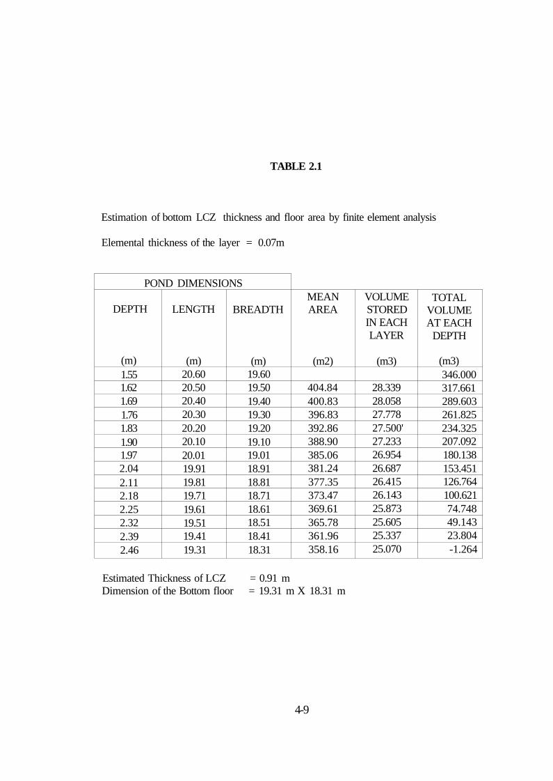
TABLE 2.1
Estimation of bottom LCZ thickness and floor area by finite element analysis
Elemental thickness of the layer = 0.07m
POND DIMENSIONS
DEPTH
(m) 1.55 1.62 1.69 1.76 1.83 1.90 1.97 2.04 2.11 2.18 2.25 2.32 2.39 2.46
LENGTH
(m) 20.60 20.50 20.40 20.30 20.20 20.10 20.01 19.91 19.81 19.71 19.61 19.51 19.41 19.31
BREADTH
(m) 19.60 19.50 19.40 19.30 19.20 19.10 19.01 18.91 18.81 18.71 18.61 18.51 18.41 18.31
MEAN AREA
(m2)
404.84 400.83 396.83 392.86 388.90 385.06 381.24 377.35 373.47 369.61 365.78 361.96 358.16
VOLUME STORED IN EACH LAYER
(m3)
28.339 28.058 27.778 27.500' 27.233 26.954 26.687 26.415 26.143 25.873 25.605 25.337 25.070
TOTAL VOLUME AT EACH
DEPTH
(m3) 346.000 317.661 289.603 261.825 234.325 207.092 180.138 153.451 126.764 100.621 74.748 49.143 23.804 -1.264
Estimated Thickness of LCZ = 0.91 m Dimension of the Bottom floor = 19.31 m X 18.31 m
4-9

The finite element analysis gives the thickness of LCZ to be 0.91 m. It is
interesting to note that this value of 0.91m for the LCZ depth almost coincides with the
value of 0.90m as the optimum LCZ depth obtained from modeling studies. Of course
this agreement comes for an assumed pond efficiency of 13%. The pond bottom
dimensions of 18.8m X 17.8m obtained assuming LCZ thickness are close to the value of
19.3 m X 18.3 m obtained using storage volume estimation method.
The present solar pond is intended to deliver daily a total thermal power
output of 500 Kwh and this power has to be extracted in one hour duration. This could
be achieved by extracting heat from the LCZ by hot brine withdrawal method using a
heat extracting system built outside the pond. In order to get the required heat output, the
required hot brine mass flow rate (m) can be estimated, by knowing the expected
temperature drop AT across the heat exchanger and the specific heat capacity of the hot
brine (Cp). With an assumed temperature drop of 8°C and Cp of 3270 J/kg/ °C the
required mass flow rate of hot brine is estimated using the relation,
Qu m = ---------- 2.8.
Cp T
and is found to be 19 Kg/s. For a brine density value of 1160 kg/m3, the volume of
brine to be circulated through the heat exchanger is 58.68 m^/Hr.
The total volume of the storage zone is 346 m3. So the hot brine
withdrawal at a rate of 58.68 m3/Hr is not expected in anyway to affect the zone
boundary and produce mixing, because of the cushioning/smoothening effect provided by
the large volume (346 m3) of brine stored in the LCZ of thickness 0.90m. Moreover
this thickness also ensures the fixing of the brine extraction diffuser a little below the
LCZ - NCZ boundary so as to avoid the erosion of gradient layers due to entrainment and
50

the placing of the reinjection diffuser a little above the bottom floor of the pond in order
to reduce turbulence in the LCZ layers and to avoid lifting of silt to the upper regions of
the pond depth which would affect the pond clarity and performance. However, the
practicality of achieving this desired result lies with the suitable design of brine
extraction diffuser, heat extraction system and brine reinjection diffuser and these
designs have been given in chapter 3. Hence with the simple design given above the
following pond dimensions have been obtained.
I. AREA:
a) Solar collection area of the pond at its top surface
b) Solar collection area of the pond at its bottom Floor
c) Solar collection area of the pond at LCZ-NCZ Interface
d) A free board (U.25m) the top peripheral dimension and its area are
and
497 m2
(22.8 ra
353 m2
(19.3 m
404 m2
(20.6 ra
(23.2 m 515 m2
X 21º. 8
X18.3
X 19.6
X22.2
m)
m)
m)
m)
II. ZONE THICKNESS
Thickness of UCZ Thickness of NCZ Thickness of LCZ
= 0.25 m = 1.30 m = 0.90 m
III. TOTAL DEPTH OF THE POND = 2.45 m
IV. a. Expected Thermal power extraction from the pond b. Hot brine flow rate c. Desired temperature drop across the heat exchanger d. Assumed Average diurnal temperature rise of the pond e. Volume of brine stored in the LCZ (0.9m)
= 500 Kwh/Day = 58.68 m3/Hr = 8ºC = l°C/dav = 346 m5
51
2.5. CONSTRUCTION OF SOLAR POND
INTRODUCTION
Hull et al. (1) have pointed out that the Solar Pond establishment and
operation most critically depend on three aspects viz) site, design and construction and
management/raaintenance (1). The selection of site, design and construction have to be
made carefully. One of the major challenges in solar pond technology is the leak proof
containment of the brine. Several ponds in the world over leaked because of the failure of
the lining scheme (27,34,57,88). In India, all the ponds had leakage problem one time or
the other during their operation due to the failure of the lining scheme (88). So selecting
suitable materials and methods of lining the pond for leak proof containment of the brine
are very important aspects for solar pond construction. Site selection is another aspect
which is to be taken care of. Another important aspect is pond establishment with brine
of suitable concentration and/or concentration gradient. Once the pond has been
established, it has to be maintained/managed properly to get the desired returns from the
pond. Studies on these aspects have been covered in the following pages with reference
to Pondicherry Solar Pond.
2.6. SITE CHARACTERISTICS
For a particular location to be appropriate for a solar pond, there are
several essential requirements that must be satisfied.
* Use for the heat or Power Produced
* Access to water
* Access to salt
* Disposal method for surface brine removed
52
In addition to the stated essential requirements, there are desirable
characteristics for solar pond site, most of which are obvious
* High insolation
* Moving water table not too close
* Low wind speed
* Absence of Wind-borne debris
* Relatively flat site
* Soil with good cohesion for walls
For economic applicability of any solar thermal system, as a rule of thumb
2000 sunshine hours per year is desired (100). It is observed from the collected data that
Pondicherry (12°N) receives 3000 sunshine hours per year and high insolation ranging
from 4.8 to 6.4 Kwh/day is available for at least 300 days a year.
Operation of a solar pond requires enough water for pond filling, for make
up in order to compensate for the evaporation losses and to do surface washing in the
process of maintaining low salinity at the surface zone of the solar pond. The water table
depth near the solar pond site has been found to be more than 15m. A borewel has been
established at a distance of 150m from the pond site to provide fresh water for the pond
requirements.
Macdonald et al. (81), Hull et al. (1), Al-Marafie et al. (80) and Mehta et
al. (64) have all reported that high wind speed increases evaporation losses appreciably
and destabilize the salt gradient layers. Several investigators like Tabor and Doron (26),
Golding (45) have used aritificial wind breakers and wave breakers to offset the ill
effects of high wind speeds. However, there are also ponds like Argonne National
53
Laboratory(ANL), Tennesse Valley Authority(TVA) and Miamisburg ponds which are
located at sites with natural wind barriers. In these sites a combination of topography,
trees and pond fencing provided significant wind protection and floating barriers have
become unneccessary.
The solar pond site at Pondicherry is located in a small natural depression
and inside a cashewnut plant groove. Further, nearly 10m tall casurina tree belt has also
been developed around the pond site, at a distance of more than 30m from the pond, so
that the shadow of the trees might not have any effect on the solar energy collection of
the pond. As a result of these environmentally friendly arrangements which provide a
natural wind barrier, only very low wind speeds ranging from 0.1 to 4.0m/s have been
observed at the pond site. So wind breakers and wave breakers may not be required for
the Pondicherry Pond.
The depth of water table decides the performance of the pond. If the
water table depth is less than iOm, it would lead lu hevay ground heat lo.ss, vwudi inimn
would adversely affect the temperature achievable in the storage /.one (100). The present
pond site is found to have a water table depth of more than 15m and may give rise to low
ground losses only and hence the performance of the solar pond is not expected to be
affected adversely.
Abundant supply of NaCl salt can be easily procured from the nearest salt
works either at Marakkanam (15km) or at Vedaranyam (200km) at a relatively cheap rate
of Rs. 600/metric tonne ($18/lonne).
54

It is better that the solar pond site is located very close to the point of use
(1). In this case the electric power generated from the pond could be supplised to the
nearby hostels of the Pondicherry Engineering College buildings which are located at a
distance of around 60m from the pond site.
A seperate saline water evaporation tank has to be provided at the site to
densify the surface brine, drained from the pond so that it can be reutihzed for the pond
application. This tank could also be used as a salt mixing tank during the initial filling of
the pond. Such a tank has been provided at the pond site. Also in case of emergency it is
also possible to drain the salt solution to the sea without polluting die environment.
To see, to what extent the soil has cohesion for walls, the soil properties
have been analysed. The analysis was made upto a soil depth of 15.0m by collecting
samples by drilling holes in the earth. The soil at the Pondicherry site was classified as
red cla\ey siii\ sand with percentage composition of clay, sill and sand as 12'/ , IK'.i and
70% (100). The permeability of the soil at the pond site was measured at different
depths using a permeameter (101), and the average values obtained at different depths
from the top surface upto 15.0m depth are given in table 2.2.
55

TABLE 2.2.
PREMEABILITY FOR THE SITE SOIL
SL.
NO.
1.
2
3
4
5
6
7
8
9
10.
11.
12.
13.
14.
SOIL DEPTH
(m)
Top surface
2.0
3.0
4.0
6.0
7.0
8.0
9.0
10.0
11.0
12.0
13.0
14.0
15.0
DRY DENSITY
gm/cc
1.690
1.645
1.916
1.864
1.248
2.287
1.906
1.573
1.718
1.715
1.775
2.060
1.695
1.665
PERMEABILITY
cm/s
1.76 X 10"4
2.01X10'4
1.98X10'4
2.14X10"4
6.77X10"5
6.91X10⁻⁴
8.57X10⁻⁴
2.12X10"3
8.30X10'6
2.39X10"3
2.41X10⁻⁴
6.22X10⁻⁵
1.72X10"3
1.52X10'5

The table 2.2. indicates thai the permeabilities of the site soil at its various
depths from top surface upto 15m lie within a range of 1.72 X 10"̂ cm/s to 8.30 X 10"̂
cm/s. This range of values agrees very well with the range of 10"̂ to 10"^ cm/sec given
in the soil classification chart IS 1498-1970 and the site soil is considered as highly
permeable. Though the Pondicherry pond site satisfies almost all essential and desirable
requirements of a good pond site, the only aspect in which it deviates from the
requirements of a good pond site is the relatively high permeability of the soil.
The basic requirement for the pond containment volume is low
permeabilty of the soil. When the native soil at the site does not provide low enough
permeability, low permeability clays and/or some type of membrane liners would be
required for the containment of the brine, (1). Since the soil at the Pondicherry pond site
has comparatively high permeability, clay and/or membrane lining has to be used for the
brine containment.
2.7. EXCAVATION AND EMBANKMENT
In most places, the pond excavation is carried out with heavy earth
moving equipment (1). However, in the Bangalore pond the e;irth excavation work was
carried out employing manual labour (69). In construcing the 500m2 Pondicherry pond
used for the present study, manual labour alone has been employed. The usual practice
of adopting a combination of an excavation and an embankment made of the earth
excavated, has been followed for constructing the present pond. The amount of earth
that must be moved to make a pond of specified depth is not the volume of the pond; but
the volume of earth moved is only what is needed to build up an embankment around the
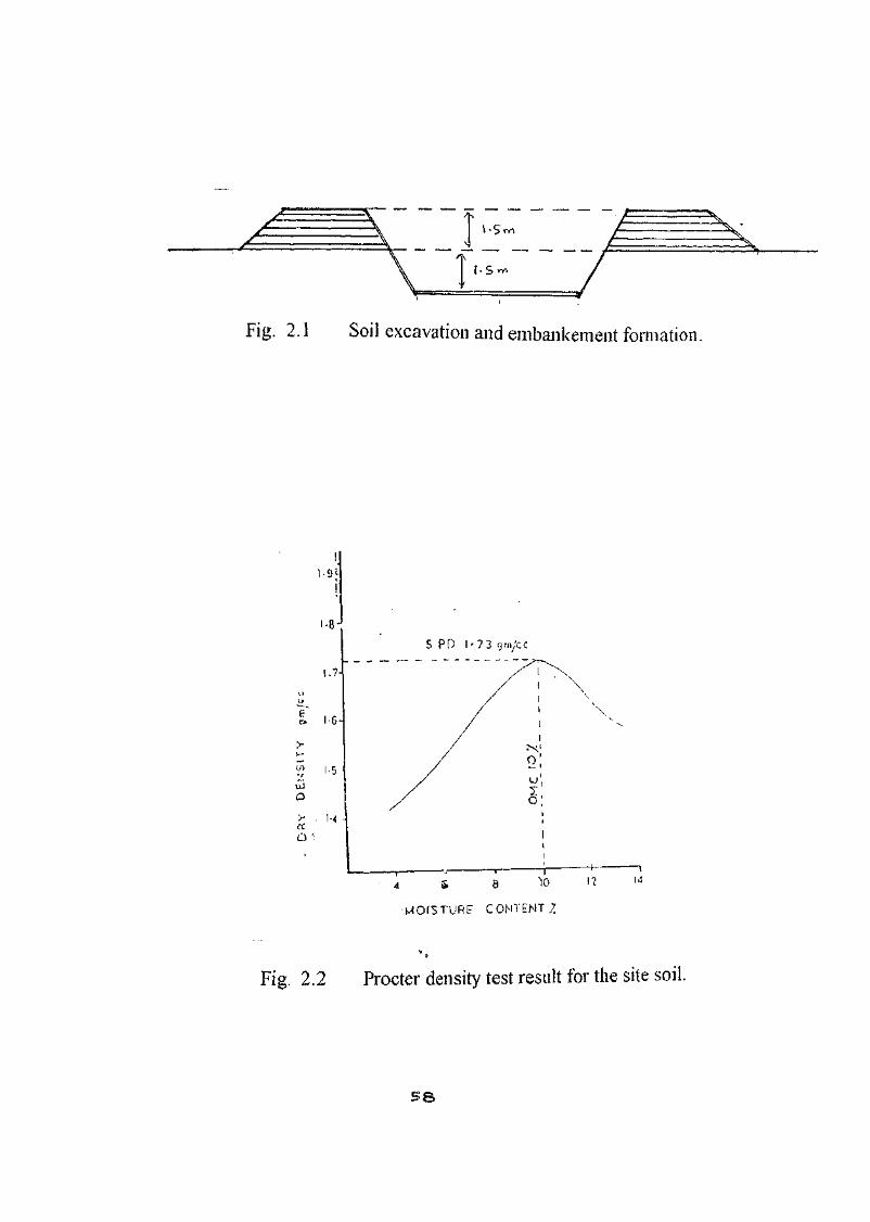
perimeter of the pond (1). For the Pondicherry pond, the earth was excavated to a depth
of 1.5m and the excavated soil was used for the formation of embankment around the
perimeter of the solar pond to a height of 1.5m from the ground level (Fig. 2.1).
57

Stable walls are essential for the longevity of a pond and a firm base
should be provided for lining installation, if required. Embankments should be
sufficiently compacted to avoid slumping i.e. Ihe falling or sinking of material down the
side wall. For the present pond, the compaction of the embankment was performed
manually using hand pulled stone rollers. Proctor test (107) was performed to quantify
the compaction level of the bund wall. The dry density of the soil could he estimated
from the samples collected from various locations of the slope wall of the pond. Proctor
test for the site soil gives a maximum dry density of 1730 kg/m-̂ for an optimum
moisture content of 10%. Gupta (100) has given a plot between the moisture content and
dry density and the curve is shown in fig. 2.2.
From a knowledge of the dry density and moisture content, the
compaction level of the bund soil could be estimated, taking the maximum dry density to
give 100^ compaction. If the bund compaction is more than 90% of maximum dry
density it is considered to be adequate for stable wall structure. When the compaction
level of the bund was measured, it was found to be close to 90% of the maximum dry
density thus indicating that the bund walls would be stable.
As mentioned under pond site characteristics, clay and/or membrane
linings have to be used for brine containment since the soil is highly permeable.
Membranes used as liners must have superior strength and extension properties, very
good stability in the operating temperatures anticipated, (about 100'c), resistance to
ultraviolet degradation, good puncture resistance, good tear resistance, high degree of
dimensional stability under dead load, large width to reduce the number of seams made
and low cost (1). Chlorinated Polyethylene films (CPE) (20,34), Ethylene Propylene
Dicne monomer (EPDM) (26,41,60), XR - 5 (42,57,80), High density Polyethylene
S$
HOPE (44.1-4), Polypropylene (59) and low density polyethylene LDPE (69,88) are some
of the films that have been widely used in solar ponds. It is interesting to note that for
most of the ponds in India, LDPE liner has been used (69, 88). The LDPE liner has the
advantage dial it is manufactured upto 12m width which in turn facilitates reduction in
the number of joints. Further the LDPE films are manufactured in India and are easily
available in the market at a low cost of Rs. 35/m2 (~ a dollar/m2) for the 250 u. film. It
also has good elongation characteristics (77). So in the Pondicherry pond also, the LDPE
liner has been used.
In several ponds, liners alone have been used for the containment of pond
solution. Hull (42), Swift et al. (57) and Al-Marafie et al.. (80) have used XR-5 liner
alone in their ponds. Nielsen and Rabl (20) and Shah et al.. (34) have used Chlorinated
Polyethylene liner alone. Collins et al.. (44) have used High density Ployeihylenc liner
alone in their pond. Srinivasan (69) has used LDPE films alone in his Bangalore pond.
So in the present pond also at the first instance, inorder to contain the brine within the
pond volume, black low density polyelheylene (LDPE) membrane liners alone have been
used. Before installing the LDPE liner, the soil surface of the pond bottom and slope
wall were smoothened so that they are free from sharp stones, tree roots or other
protrusion by plastering the slope and bottom floor with a mixture of fine grain sandy
silty soil with bentonite clay. Prior to the establishment of the pond, rain has caused
severe erosion of the prepared surface [plate I] and it was corrected latter. In order to
understand the heat How pattern through bottom floor and bund walls 29 numbers of 18
SWG Copper - Conslantan thermocouples have been installed and the locations of the
thermocouples are shown in fig 2.3. Srinivasan (69) has used two LDPE liners for the
containmciii of brine in the Bangalore pond. So in the present pond also, two LDPE
Liners have been tried first. Two layers of black LDPE liners, thermally welded to give
large area, were used to cover the entire pond bottom and slope of the pond.
6 0

Bund erosion due to rain.

62 .

For the 500 m~ pond 36mX36m liner dimension is adequate. Four strips
of LDPE films of size 10mX40m were taken and welded to form a 40mX40m membrane
and was laid in the pond as shown in figure.2.4. The excess film area has been cutoff.
A second LDPE film layer was installed in the same way. The joints formed across I
strip and II strip (Joint I) and III strip and IV strip (Joint 3) were found to run along the
lengthwise side of the slope walls and were found to be located well within the heat
storage zone of the solar pond. The joints which run along the bottom of the floor is
acted vertically with a uniform hydrostatic thrust of the pond brine and hence will not be
subjected to any resultant stretching force, whereas it is not so in the other two sealed
joints which run along the length of the sloping wall.
Bentonite clay powder and china clay powder mixture procured from
Bhavanagar, Gujarat, about 1600 Km away from Pondichcrry, were used as a soil
cushion, between the two liners and between the bottom liner and the soil earth to a
thickness of 5 cm and 2.5 cm respectively. The details of the pond lining have been
given in the figure 2.5. The pond filling process is shown in Plate 2. The establishment
of various zones of the pond was performed in September 91 using Zangrando's
redistribution method (described elsewhere). A small 70 m^ pond with a depth of 2.0m
lined with 2 layers of LDPE film has also been constructed and this pond has been used
for initial salt mixing and this would also serve as the evaporation pond to collect surface
drained brine of the pond. This 500 m? solar pond worked well uplo a heat storage zone
temperature of 69"C and after that leakage through the LDPE liner along the edge of the
heat sealed joints, could be detected visually from the top of the pond. This fracture in
the LDPE liner was observed for a length of about 3m. This has lead to daily drop of 3
to 5 cm in llic level ol" the top surface of the water. Immediately the pond was emptied in
Jan.92. The pond brine was pumped through the sewage canal of the Pondichery
Engineering College and was discharged into the sea. The pond was allowed to dry.
63

6^-
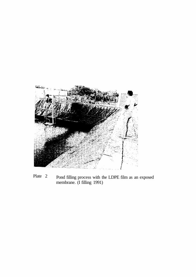
Plate 2 Pond filling process with the LDPE film as an exposed membrane. (I filling 1991)

So, before filling the pond for the second lime, an attempt has been made
(o identify I he causes for the leakage of the pond and to see what modifications could be
made in the lining technique inorder to contain the brine without leakage.
Siegel et al. (103) have pointed that while laying the liner films the seams
should be oriented down the wall slopes instead of across them. But unfortunately in the
lining scheme used, it so happened that they were across the wall slopes. Further the
LDPE liner was found to have cracks along the folding creases of the film on the sun
facing walls of the pond. It is to be noted that the film has been used as an exposed
membrane and the cracks were prominantly noticeable in the area exposed to the solar
radiation. The degradation of the liner material due to solar radiation might have caused
these cracks. These two effects indicate that the liner has not been properly installed.
bYactures of the LDPE. film has been observed along the edges of the heal
sealed join is. This indicates weakening of the film at the edges of the heat sealed joints.
The hydrostatic pressure ol' the brine acting on the overlap joints o( the LDPE films
further weakens the edges of the joints. The temperature rise also aids to the weakening
of the edges of the joints and these causes may be responsible for the observed fracture of
the films along the edges of the heat sealed joints.
There was slumping ie) the falling or sinking of material down the
sidewall thus damaging the installed LDPE liner at the bottom periphery of the pond.
This shows that the slope walls are not stable and this lack of stability of the slope walls
could be attributed to the high permeability of the site soil. Experiments have been
conducted 10 identify suitable techniques to overcome the problems mentioned above.
66
2.8. STUDY OF THE STRENGTH OF LDPE FILM
As mentioned earlier, visual observations made on the pond liner revealed
lengthy fractures along the folding crease of the LDPE film. Inorder to understand the
cause for this, studies have been conducted to find the machanical characteristics of
1) afresh LDPE film
2) a LDPE film exposed to sun for a period of 12 months called the degraded film and
3) a LDPE film sample soaked in NaCI Solution of 25% salinty maintained at a constant
service temperature of 100"C for a period of 10 days referred to as aged film.
These studies were conducted using the testing facilities available at the
Central Insiitute of Plastic Engineering and Technology, Madras (Chennai). The tensile
strength at break, the elongation at break and carbon black content of the samples have
been studied. The tensile strength at break and the elongation at break have been studied
in the machine direction as well as in the transverse direction. The results are presented
in table 2.3. The table 2.3, clearly shows that the mechanical properties and carbon black
content are drastically reduced when the film is directly exposed to the solar radiation,
(i.e., for degraded film), thus indicating that it has almost lost its characteristics. It has
been found that such a degraded film easily gets cracked and fractured on just bending or
folding it. Considering the aged film (ic the one soaked in 25% salt solution with a
constant service temperature of 100"C), it can be seen that the tensile strength at break in
the machine direction very marginally increases by about 7% of the normal film while
the tensile strength at break along the transverse direction decreases by about 24%. The
67

TABLE NO. 2.3
TENSILE STRENGTH OF NEW, DEGRADED AND AGED LDPE FILMS
PROPERTY
1. Tensile Slrcngih at break in machine direction
2. 'Tensile slrcngih al break in transverse direction
3.Elongalinn al break in machine direction
4. Break in transverse direction
5. Carbon black content
Sltl
ASTM DX82
ASTM DX82
ASTM D8X2
ASTM DXX2
ASTM D160:}
UNIT
Kg/Cm2
Kg/Cm2
%
%
%
VALUE
NEW FILM
157.0
101.0
544.0
652,0
2.1429
USED/ DEGRADED
98.0
71.0
17.0
9.0
1.2549
AGED FILM
166.0
145.0
421.0
542.0
1.5918
68
elongation in both the directions decreases (about 16% I'or transverse direction and about
22% for llic machine direction) and the carbon black content also decreases by about
24%'. Such changes have occured within a period of 10 days.
This study clearly indicates that
1) the film in direct contact with brine solution at constant high temperatures looses
its original characteristics and therefore may become susceptible to fractures in
the long run and
2) the LDPE film degrades very easily when it is exposed to direct sunlight. So to
understand the degradation mechanism, the degraded film and the fresh film have
been analysed wiLh the Fourier Transform Infrared (FTIR) technique.
2.9. FTIR Analysis of LDPE Films
Fresh and degraded samples of LDPE film of 250 u thickness similar in
quality and thickness were chosen for spectroscopic study. The Perkin-Elmer FTIR
Series 1600 - Fourier Transform Infrared spectre Photometer has been used to obtain the
FTIR spectra of the fresh and degraded samples. The FTIR Spectra were obtained for
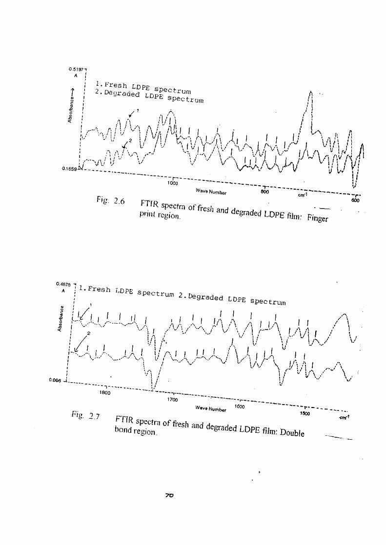
the finger print region (1000 cnW - 700 cm"') and also for the double bond region
(1850cm"1 - 1500 cnr'jfor both fresh and degraded LDPE films. The FTIR spectra of
fresh and degraded LDPE films are shown in figure 2.6 for the finger print region and in
figure 2.7 for the double bond region. The IR Spectra are formed due to the vibrational
excitation of particular functional groups. Vinylidene and terminal vinyl group have
strong absorption maximum in the finger print region and the carbon-oxygen double
bond of a kctonic group has a strong absorption band in the 1680 -1760 cm-1 region.
69
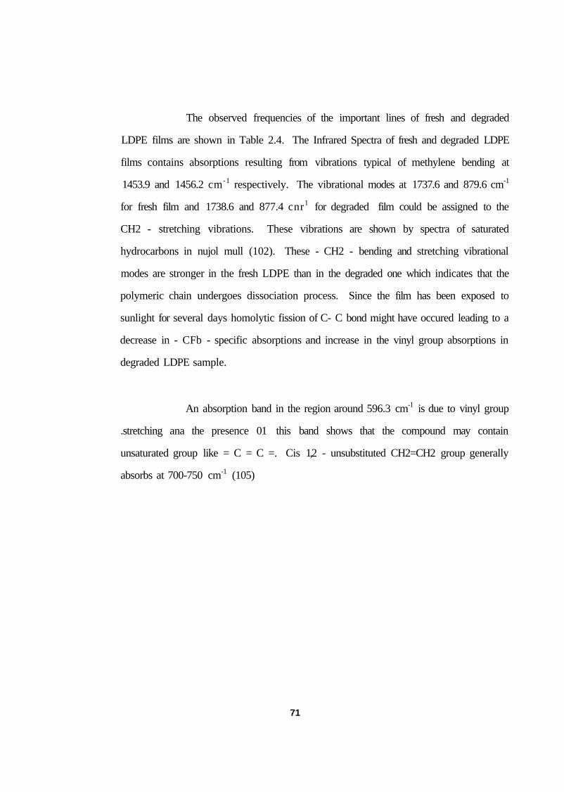
The observed frequencies of the important lines of fresh and degraded
LDPE films are shown in Table 2.4. The Infrared Spectra of fresh and degraded LDPE
films contains absorptions resulting from vibrations typical of methylene bending at
1453.9 and 1456.2 cm-1 respectively. The vibrational modes at 1737.6 and 879.6 cm-1
for fresh film and 1738.6 and 877.4 cnr1 for degraded film could be assigned to the
CH2 - stretching vibrations. These vibrations are shown by spectra of saturated
hydrocarbons in nujol mull (102). These - CH2 - bending and stretching vibrational
modes are stronger in the fresh LDPE than in the degraded one which indicates that the
polymeric chain undergoes dissociation process. Since the film has been exposed to
sunlight for several days homolytic fission of C- C bond might have occured leading to a
decrease in - CFb - specific absorptions and increase in the vinyl group absorptions in
degraded LDPE sample.
An absorption band in the region around 596.3 cm-1 is due to vinyl group
.stretching ana the presence 01 this band shows that the compound may contain
unsaturated group like = C = C =. Cis 1,2 - unsubstituted CH2=CH2 group generally
absorbs at 700-750 cm-1 (105)
71

TABLE NO. 2.4
INFRARED SPECTRAL CHARACTERISTICS OF FRESH AND
DEGRADED LDPE FILM
FRESH DEGRADED
72

Several factors can alter the frequency of this stretching mode and particularly in long
alkyl chains (104). So the band at 717.4 cm"' could be taken to represent the presence of
vinyl groups. The stretching mode vibration centered at 972.9 cm"' also shows the
existence of vinyl group both in the fresh and degraded films. This is further supported
by the absorption peaks at 1104.6 and 1106.4 cnr1 in the fresh and the degraded films.
The bands at 1622.7 cm-1 in the fresh LDPE film and 1618.8 cm-1 in the degraded
LDPE film show the presence of the vinyl group in both fresh and degraded LDPE. The
vibrational modes at 1800 - 1850 cnr1 are due to weak overtones of vinyl groups
(104,105), and are observed in both the samples under study. The above data support the
introduction of double bonds in the LDPE due to exposure to radiation, which might
have broken the C- C sigma bond. Comparing the Vinyl peaks around 1622 cm-1 for the
fresh and degraded LDPE, it can be seen that the spectral distribution is more for the
degraded LDPE than for the fresh LDPE. This shows that there is increase in the vinyl
group absorption in the degraded film as prediced earlier.
The increase in concentration of vinyl group us due to photo degradation,
which causes the breakage of the bond converting the methylene groups into vinyl
groups.
Moreover, the polymer sample contains modes due to carbonyl stretching.
Ester carbonyl absorbs at 1740.1 Cm-1 Ketonic Carbonyl absorbs (104) at 1715.8 Cm-1.
The bonds at 1712.9 and 1714.7 cnr1 respectively for fresh and degraded films indicate
the presence of Ketonic Carbonyl group. The presence of a small peak at 1712.9 cnr '
for the Ketonic Carbonyl stretching mode in the fresh LDPE film is rather surprising.
This shows that the fresh film has undergone some initial oxidation process at the
manufacturing end itself and/or during transportation for installation. The relatively
strong absorption in this region (1714.7 cm-1) in the degraded film shows the additional
73

formation of the Ketonic carbonyl group over and above the initial formation mentioned
above. The presence of Ketonic carbonyl group in the film indicates the degradation
through radical formation and subsequent oxidation. This means that a radical site is
introduced into the chain, which is subsequently attacked by the dissolved oxygen
molecule. This results in the formation of peroxide radical (105, 106)
Peroxide radical being highly reactive, attacks the neighbouring polymer
chain producing another radical carbon of the polymer backbone.
This peroxide radical causes 6-Scission in the chain leading to the
formation of ketonic Carbonyl, whose concentration gets increased. Therefore, the peak
belonging to the degraded LDPE is more prominent than that of a fresh one.
Energy needed to break a chemical bond lies between 40 and 150
K. Cal/mole. The polymer sheet undergoes photodegradation due to a homolytic C-C
bond cleavage. The energy is obtained from visible and near uv photons, which can very
well bring a chemical change. In conclusion, exposure to sunlight can induce homolytic
bond cleavage in the polymer chain.
74

Thus the solar irradiation of the film leads to hemolysis, introducing
unsaturation and generation of radical sites. The radical sites can very well react with
dissolved oxygen molccuies bringing further chemical changes. The carbonyl group
introduction is one such important reaction which is supported by the IR spectral data.
The LDPE is normally composed of cross linked random coif which gives tensile
strength to the film. If the random coil undergoes cleavages due to exposure to light the
long chain hydrocarbon is split into smaller units which generally loose their strength and
hence the tensile strength of the film will be reduced. It has already been shown, from
the tensile strength studios of fresh and degraded LDPE, films, (Table 2.3). that the
tensile strength of the film decreases enormously on exposure to the solar radiation.
Thus the Infrared spectral analysis of the fresh and solar light exposed
samples shows that the latter undergoes photo degradation ie, long alkyl chain polymer is
homolytically split into smaller units, ultimately unsaturation and radical sites are
generated. These chemical changes leading ui the splitting ot long chain hydrocarbon
into small units, results in the reduction in the tensile strength of the films exposed to
sunlight.
These sludies clearly indicate that the LDPE film (I) when exposed to
direct sunlight undergo fast degradation due to photo oxidation and become prone to
fractures and cracks. (2) when immersed in hot NaCl solution also, they undergo
degradation and become susceptible to fractures and cracks. So the LDPE film used in
the solar pond must not be exposed to direct sunlight and must not be used to contain hot
brine. This means that the films must be used as submerged membranes only. These
conclusions are consistent with the conclusions arrived at by Raman and Kishore while
studying the pond lining schemes (77).
75
2.10. THERMAL WELDING OF LDPE FILMS
An electrical heat sealing iron of 1.5 KW fabricated locally (Fig.2.8.a &. 2.8b)
was used for preparing heat sealed LDPE film joints. The film joints were tested for
their tensile strength, using the FIE TNE Series 9200 - Tensile strength measuring
machine. Strips of thermally welded joints, including edges of the joints, of length 15
cm and width 2.5 cm were cut from the sealed overlap joint and one end of the strip was
held in position in the fixed end ol' the chuck and the other end was fixed with the other
chuck, a mechanically movable part of the machine. A 10% variation in speed has been
selected for pulling the film strips. These studies indicate that sealed joint has about 65'A
of the tensile strength and about 30'/?. of the elongation of the fresh unwelded film while
at the edges of the joints the tensile strength is just close to 5()rA and the elongation is
close to 207( of a fresh unwelded film. This shows that the films are very weak at the
edges of the joints. As a matter of fact, most of the thermally sealed joint samples were
found to get fractured near the edges of the lap joints. Keen observation of the heat
sealing iron and the method used for heat sealing revealed that the outer edge of the
metal blade of the iron was transfering the same heat to the top layer LDPE film as the
other edges are transfering to both the layers thus causing the top layer near the joint to
get overheated which inturn would affect its mechanical properties adversely making it
susceptible to easy punctures under the influence of even small stretching forces.
A close observation indicated that the 90" bend given to the blades of the
heat sealing iron is responsible for transferring excess heat to the top layer near the joints.
If the edge of the blades is bent at 45' with the edges rounded off, this problem could be
avoided. So the heat sealing iron has been modified and all the 90" sharp bends of the
blades of the heat sealing iron were made to have tapered edges of 45"slope and were
smoothened using a grinding stone. There are three blades in the iron and the seperation
7 6

Fin. 2.8a Electrical heat sealing iron (top view)
wooden Handle
Thermal insulati AC Mains
Mild steel Base plate
Fig. 2.8b Electrical heat sealing iron (cross section)
77
between the adjacent blades is 1.2 cm. So a maximum of three heat sealed joints with
1.2 cm gap between consecutive joints could be produced at a time.
The electrical heat sealing iron and the arrangement for heat sealing the
LDPE film layers are shown in figure 2.9a and 2.9b. For heat sealing the LDPE film
layers, the temperature of the blade of the heat sealing iron was maintained at 150°C and
its heating contact time on the LDPE film overlap was selected between 5-8 seconds as
suggested in the manual on Canal and Reservior Lining released by the Indian
Petrochemical Corporation Ltd. A strip of cellophane sheet was placed between the film
and the heating blades to avoid the risk of film adhering to the blades.
2.11. OPTIMUM WIDTH FOR HEAT SEALING OF LDPE FILMS
Seams with different widths of overlapped joints, with double, triple and
multiple sealed joints with or without having non heating contact space between the two
liners have been fabricated for the present study and these joints have been tested for
their tensile strength and elongation characteristics. From these studies, an attempt has
been made to identify the best possible overlap joint and also the suitable width for the
overlapping joint of two LDPE film layers. The tensile strength and elongation studies
of the samples have been made using F1E-TNE Series 9200 - Tensile strength machine.
These studies have been conducted on 250 u thickness LDPE films.
The maximum tensile strength Fjyiax in Newtons, elongation at maximum
load E p m a x in mm and the elongtion at fracture point EpRp in mm have been measured
and are presented in Table 2.5
7&

2.9a Modified heat sealing iron with 45° tapering.
Heat sea l ing iron
i l m " " • • " ' • - • ' • *
• > • • • ' . - • . ' , . < • • . - - , - ,
Wooden T a b l e
(
' '"l
Fig. 2.9b Complete heat sealing aiTangement.
V9
Cellophomsr Sheet f~

TABLE NO. 2.5
TENSILE STRENGTH OF HEAT SEALED LDPE JOINTS
So
From the table it can be clearly seen that when the total width (TW) of the
joint is increased from 7.2 to 14.4 cm. keeping the gap between the welded joints
(GBWJ) zero, both the tensile strength and elongation decrease appreciably, whereas
when the TW is changed from 10.8 to 12.0 cm keeping GBWJ at 4.8cm, the tensile
strength decreases but the elongation increases appreciably. A double sealed joint with a
TW 3.6 cm and GBWJ 1.2 cm has the least tensile strength and least elongation. A triple
sealed joint with a TW 6.0 cm and GBWJ 2.4cm is much better than the double sealed
joint of TW 3.6 Cm. The behaviour of this joint is close to that of the joint with 7.2 cm
TW and zero GBWJ. Though a multiple sealed joint with a TW 10.8 cm and a GBWJ
4.8 cm gives the same tensile strength as the fresh unwelded film, it has very poor
elongation characteristics. So it can be concluded that the triple joint with 6.0 cm TW
and 2.4 cm GBWJ and the full overlap joint with 7.2 cm TW and zero GBWJ appear to
be better than the other type of joints. It could be noticed that none of the joints have the
same elongation characteristics as that of a fresh unwelded film.
With the presenL heat sealing method, ii was observed that all film joints,
if at all they fail, fail only in the middle portion of the joint and not along its edges and
this has been achieved due to the modification made with the heat sealing iron. Hence it
has been established that heat sealing joints with a tensile strength some what close to
that of a single weld-free LDPE liner can be fabricated. Optimum heat sealing width of
7.2cm, with full overlap heating of the film or a 6.0 cm width of single heating triple
sealed joint can be used during the fabrication of wide width LDPE film membranes.
8l
2.12. SOIL ANALYSIS FOR CLAY SELECTION
The use of LDPE films alone for containing brine solution was not
successful in containing the brine solution in the present pond. Studies have indicated
that the LDPE films must be used as submergible membranes only. So for the second
filling of the pond, compacted clay and submerged LDPE films have been tried for the
containment of the brine in the pond. Tabor and Doron (26) have suggested that multiple
layers of plastic membrane in between compacted clay, could be used for pond lining.
Motiani etal (88,89) have utilized multiple LDPE membranes for the Bhuj Pond lining,
utilizing locally available white clay.
In the first filling of the 500 m2 solar pond, dry bentonite and china clay
powder mix was used only as cushioning material. Even for this, the clays had to be
procured from Bhavnagar, Gujarat which is 1600 Km from Pondicherry and the cost of
the material was Rs.2500/ per Metric tonne. The time factor involved in this process was
also high. It took as many as 60 days or more between ordering for the clay and the
supply of the clay at the site. So a search was made to see whether any suitable clay for
pond work is locally available so that the pond lining cost could be reduced and the time
factor involved in procuring it could be minimized. So a search was made for suitable
clay for pond work in places lying within a radious of 25 Km from Pondicherry. The
help of local Potters were sought to identify places where good quality clay suitable for
pottery work was available in large quantities. Kendikuppam, Pakkiripalayam and
Thondamanatham are the three places that could be located and clay samples were
collected from these places and analysed in the Geotechnical Laboratory of the
Pondicherry Engineering College to test their suitability for pond applications.
82

The texture of the soils collected from the throe places have been analysed
and the results are shown in the columns, 3,4 and 5 of Table 2.6. Alman/.a and Lo/ano
(73) have pointed out thai a very good impermeability is obtained if more than 30% of
clay is present in the soil. If the clay in the soil has higher percentage, the soil will be
more impermeable. In the three selecled places, the percentage of clay in the soils is
more than 30, thus indicating that these clays are suitable for pond lining.
Test results of the soil samples collected from Kendikuppani.
Pakkiripalayam andThondamantham have been presented in Table.2.6.
83

TABLE NO. 2.6
SOIL ANALYSIS OF LOCALLY COLLECTED CLAY SAMPLES
SI.
NO
1
1.
2.
3.
Sample
2
KENDIKUPPAM
PAKKIRIPALAYAM
THONDAMANATHAM
Sand
%
3
32
23
20
Silt
%
4
25
30
23
Clay
%
5
43
47
57
n. %
6
44.7
46.5
58.5
l'L %
7
23.8
23.3
31.5
ii'=
(I.I.
I'D
%
8
20. 9
23. 2 27
Soil
Type (IS
I49K-
1970)
9
CL
CL
CH
l'i.kiiik';ibilily
I 'm/s
10
10'6 to 10-8 (8x10⁻⁷) 10"6 to 10-8 10"6 to 10-8
Compact!
on
Charactcri
sties
11
Fair to Good
Fair to Good Fair to Good
64-

The mechanical properties such as liquid level (LL), Plastic limit (PL) and
plasticity index (Ip) have been determined for the three local clay samples and they are
represented in fig 2.10.a. The plasticity index value has been calculated using the
relation
Ip = LL - PL -----------------------------2.13
The liquid limit was found using the Casagrande test and the PL value
using the standard techniques (107). These values are used to locate the soil type from
the plasticity chart shown in figure 2.10.1). The results obtained are presented in Table
2.6. Among the three clay samples studied the samples collected from Kendikupnarn
and Pakkiripalayam villages have been identified as CL type clay and the clay of
Thondamanatham village as CH Type. The CH Type clay is an inorganic clay with high
plasticity; the CL type clay is also an inorganic clay but with low to medium plasticity,
When compacted, both these types have impervious character (101).
The CH Type clay possesses a high plasticity index and has a higli
shrinkage limit SL (101), high compressibility when compacted and saturated (101) and
consequently it is expected to swell when it contacts water. The CL type clay on the
otherhand has lower plasticity index and reduced shrinkage limit and medium
compressibility when compacted and saturated, consequently will have less swelling on
addition of water. From these contrasting properties of the CL type and CH type clays, it
appears as though the CL type clay is slightly better than the CH type for pond
applications, eventhough, Almanza et al. (67) have contended that both the CL and CH
Types of clay are suited for pond lining.
85


87

The land owners of Thondamantham and Pakkiripalayam were not willing
to sell the clay from their lands for pond requirements, while Kendikuppam land owners
readily came forward to provide the required quantity of clay (25 Metric tonne) for the
pond. Hence Kendikuppam soil alone has been further studied. Its permeability
characteristics and the optimum moisture content have been found. The Proctor
compaction data for the soil is given in figure 2.11. Kendikuppam clay was found to
have a maximum dry density of 1.712 gm/cc with an optimum moisture content of
21.3%. Using Permeameter, the permeability was determined and was found to be 8.0 X
l(.)"7 Cm/S for its optimum compaction condition. Almanza et al. (67) and Almanza and
Lozano (73) have reported permeability values of the order of l()-7 cm/s for Kaolinite
and Bentonile clays used by them. Raman and Kishore have reported a value of the
order of 10"8 cm/s for Kaolinite clay of Bhuj, Gujarat (India). The permeability obtained
for Kendikuppam clay is slightly higher than the values for Kaolinite and Bentonite clays
but neverthless of the same order and this clay could be used for pond lining work. This
clay costs only Rs.250/- per metric tonne while the bentonite clay procured from
Bhavnagar costed Rs.2500/- per metric tonne i.e.? ten times as costly as the local clay.
These studies indicate that the following points are to be taken care of for
successful containment of the pond brine.
1. The LDPE liner must be used only as a submerged membrane so as to avoid a)
degradation of the film due to photo oxidation caused by direct sunlight and b) the
weathering of the film due to the effect of hot brine on the film.
2. The in situ heat sealing must be done using the modified heat sealing iron with
blades bent at 45° and with curved edges. The heat sealing must be performed at
the optimum heat sealing width so that triple heat sealed joints are formed.
88


3. Since the LDPE liners have to be used as a submerged membrane, compacted clay
has to be used in between the liners and also to contain the brine. Local CL type
clay available at Kendikuppam village which is at a distance of 25Km from
Pondicherry and which is available at l/10th the cost of Bentonile clay, could be
used for the pond work. Raman and Kishore have also suggested that the LDPE
films have to be used as submerged membrane liners with compacted clay layers
in between (77). Before deciding on the lining scheme for the second filling, the
permeability of the slope walls had to be determined to see whether the walls are
stable. If the slope walls are not stable, the walls have lo be strengthened to make
them stable before lining the pond.
2.13. SOIL STABILIZATION OF BUND AND SLOPE WALL
After emptying the pond and after allowing it to dry, Proctor compaction
test was again conducted for the soil stablized on the slope wall of the pond and it was
found to have a compaction percentage ranging from 70% to 80% with an average value
of 73%. When the compaction level is greater than 90% the slope wall is said to be
stable. The average value of 73% compaction shows that walls are not stable. The
compaction once established could be reduced only by increased moisture content of the
compacted soil. Therefore the reduction in the wall compaction can be attributed to the
increase in the moisture content of the walls due to the leakage of the pond brine and/or
the entry of rain water. As mentioned earlier, the low percentage of compaction
represents instability of the pond slope walls leading to the slumping of the soil. Hence
consolidation of the slope wall of the pond is absolutely essential before resorting to re
establish the pond. This has been done in two ways. First the cement grouting was
carried out by drilling hole and pouring cement slurry to a vertical depth of 3m along the
90
anchor trench line made on the top of the bund (fig. 2.12) for every 4 metre interval of
the top perimeter of the solar pond. This was allowed to settle. After that country bricks
of size 15 cm x 10 cm x 6 cm were inserted into the slope wall such that more than 75%
of its thickness was inside the wall. The bricks are arranged in a matrix form, from top
edge of the slope wall to the centre portion of the slope wall as a lenthy strip as shown in
figure 2.13 and the bricks were properly pointed with rich cement moitor. Then the
entire slope wall surface was plastered with a lean mixture of cement mortor of 1:5 ratio,
so as to have a smooth surface covering even the projection of the bricks laid on to the
wall. This smooth surface without any projection forms the base for the laying of the
LDPE liner over it. The bottom floor of the pond was completely floored with bricks
with cement plastering in order to avoid any ingiving of the pond floor. During this
operation the thermocouples at the pond floor and slope walls were relaid | plate 3|. After
strengthening the walls the lining scheme for the second filling has been decided keeping
the findings of the studies conducted on LDPE liners, heat sealing joints, liner laying and
local clay soils in mind.
The LDPE films were heat sealed in situ with the modified heat sealing iron
[plate 4] with optimum heat sealing width of 6.0 cm and triple joints. On the bottom
cement plastered brick floor of the pond is spread 5.0 cm Bentonite and Chinaclay
powder with fine sand on Lop. Over this is spread the 250u LDPE film I taken over the
walls with its heat sealed joints running vertically along the slopes of the walls in the
east-west direction [plate 4a]. There were three joints. The central seam was laid along
the central line of the bottom floor and along the centre line of the walls. The outer joints
were also laid with the seams vertical on the slope walls running almost along the corners
of the walls and along the trench intented for toe wall construction. The portion of the
Hner inside the trench of the toe wall is provided with fine sand cushion for the film. On
the top of the film is again spread 7.5 cm of Bentonite and Chinaclay wilhfine sandon top.
91

anchor trench line made on the top of the bund (fig. 2.12) for every 4 metre interval of
the top perimeter of the solar pond. This was allowed to settle. After that country bricks
of size 15 cm x 10 cm x 6 cm were inserted into the slope wall such that more than 75%
of its thickness was inside the wall. The bricks are arranged in a matrix lorm, from top
edge of the slope wall to the centre portion of the slope wall as a lenthy strip as shown in
figure 2.13 and the bricks were properly pointed with rich cement niortor. Then the
entire slope wall surface was plastered with a lean mixture of cement niortor of 1:5 ratio,
so us to have a smooth surface covering even the projection of the bricks laid on to the
wall. This smooth surface without any projection forms the base for the laying of the
LDPE liner over it. The bottom floor of the pond was completely floored with bricks
with cement plastering in order to avoid any ingiving of the pond floor. During this
operation the thermocouples at the pond floor and slope walls were relaid |plate 3|. After
strengthening the walls the lining scheme for the second filling has been decided keeping
the findings of the studies conducted on LDPE liners, heat sealing joints, liner laying and
local clay soils in mind.
The LDPE films were heat sealed in situ with the modified heat sealing iron
[plate 4] with optimum heat sealing width of 6.0 cm and triple joints. On the bottom
cement plastered brick floor of the pond is spread 5.0 cm Bentonite and Chinaclay
powder with fine sand on top. Over this is spread the 250JJ LDPE film 1 taken over the
walls with its heat sealed joints running vertically along the slopes of the walls in the
east-west direction [plate 4a]. There were three joints. The central seam was laid along
the central line of the bottom floor and along the Centre line of the walls. The outer joints
were also laid with the seams vertical on the slope walls running almost along the corners
of the walls and along the trench intented for toe wall construction. The portion of the
liner inside the trench of the toe wall is provided with fine sand cushion for the film. On
the top of the film is again spread 7.5 cm of Bentonite and Chinaclaywithfine sandon top.
91
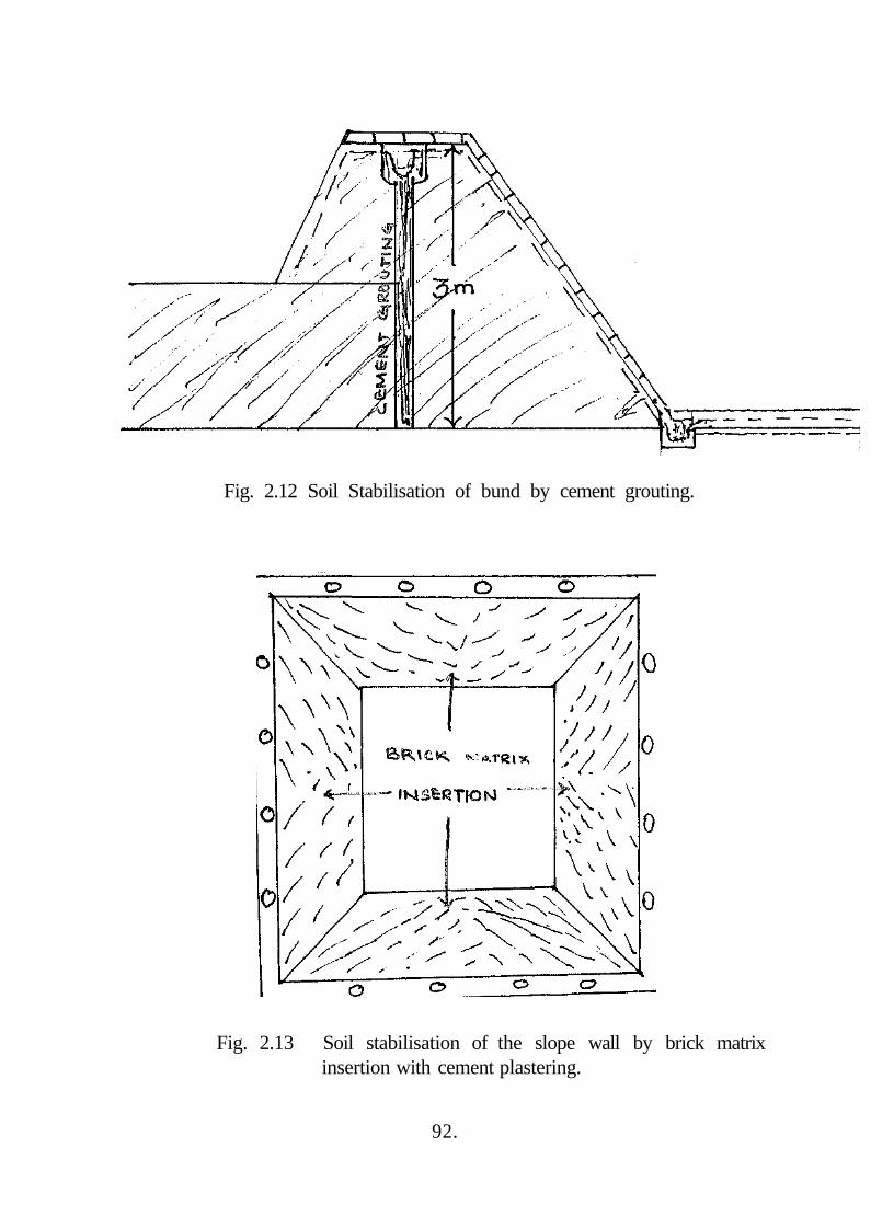
Fig. 2.12 Soil Stabilisation of bund by cement grouting.
Fig. 2.13 Soil stabilisation of the slope wall by brick matrix insertion with cement plastering.
92.

Plate 3 Laying of copper-constantan thennocouples below the bottom floor.
8**5

, ' - n
*iwt "-5SS6
Plate 4 Insitu heat sealing of LDPE film.
94.
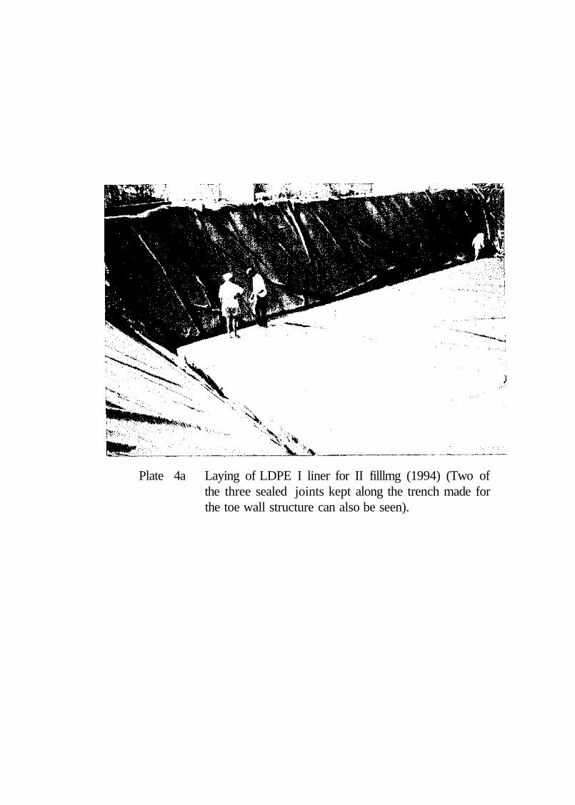
Plate 4a Laying of LDPE I liner for II filllmg (1994) (Two of the three sealed joints kept along the trench made for the toe wall structure can also be seen).

Over this is spread the LDPE film II of 250u thickness laid in the same way as LDPE
film I, but along the north-south orientation of the pond. After spreading fine sand on top
of the LDPE II liner, local clay is spread and compacted and on its top, fine sand is
spread for a total thickness of 7.5 cm. Along the trench line, over the LDPE liner is
spread fine sand. A toe wall of size 0.3 m x 0.22m x 0.4 m is constructed. Keeping the
toe wall as base, brick lining over the LDPE film spread on the slope walls with rich
cement mortor (1:3) pointing was carried out. In this process both the films have been
used as submerged membranes and the two film liners were not in direct contact with the
brine or exposed to direct sunlight.
The brine should not be in direct contact with the clay so as to avoid
mixing of brine with compacted clay. Further, the bottom of the heat storage zone could
be made black for collecting solar energy. As Srinivasan (69) could use one of the LDPE
liners of his pond as a sacrificial liner to collect solar energy and to avoid mixing of brine
with the clay used and operated the pond, it was decided to use a third LDPE film as a
sacrificial layer in this pond for this purpose. So a third LDPE liner was used as a
sacrificial liner on top of the floor for the collection of solar energy, which avoided
mixing of pond brine with clay used. The edge of the third LDPE liner was anchored on
the top portion of the toe wall using brick masonary(Fig 2.14). The air existing under the
flat LDPE liner was removed manually before it is being completely anchored with brick
masonary. The pond was established by Zangrando's redistribution method. As a first
step of this, NaCl solution of specific gravity 1.180 was pumped in to the 500 m2 tank,
from the salt mixing tank to a depth of 0.3 m. This pond filling process took 12 days to
complete. During this period the pond brine was found to get warmed up because of the
solar energy collected by the black LDPE membrane and the pond brine. At this stage the
liner III bulged and the central portion of the convex surface was above the brine level.
This bulging of the liner must have been caused by the expansion of the trapped air left
96


below the liner. By making a hole on the portion at the top of the convex bulging, the
trapped air was released out of it and the hole was patched up and the pond was
established fully. The pond could be operated without any trouble for more than 10
months. During this period enough knowledge on practical handling of the pond was
gained.
The bulging of the sacrificial liner was again noticed when the
temperature of the pond bottom reached around 75°C. Air bubbles were found to appear
intermittantly from the central portion of the pond and they subsided automatically
within a day or two. Localized bulging of the film has also been noticed. When the pond
temperature was around 75° C, heat extraction was done. Due to the failure of the suction
hose, the heat extraction process was disrupted. This resulted in the increase of the HSZ
temperature. When the pond temperature reached above 80°C, it leaked along the bottom
periphery of the pond in a few locations and was confirmed from the salinity profile, the
decrease in level of the pond surface water and the temperature history of the pond floor
thermocouples. So the pond was emptied to study the causes of the leakage and to find
ways and means of correcting it. Inspection of the pond liner after emptying the pond
indicated 1) lengthy cracks along the folded portion of the LDPE film which was laid
under the toe wall portion and inserted along the pond side edge of the toe wall, and 2)
the LDPE liner laid under the local clay along the bed portion of the pond had mm
fractures and mm holes [plate 5].
The first of these two indentified defects could have been caused by the
lack of cushioning material for the films in the inner edge of the toe wall region. There
was just clay smearing for smoothness of the wall. When the pond temperature was high
(about 80°C) the moisture in the clay smear would have evaporated making the smear
harder with angularities and developing sharp cracks also. This could
98

f ' t, , \ f J
.;,Vfcy W
Plate 5 LDPE II liner with mm holes and fractures.

have lead to the fracture in this region. The mm fractures and mm holes observed on
liner II could have been caused by the rough contours in the local clay on the top of the
liner as well as angularities of the grains of sarid. The formation of contours under the
liner can be attributed to the poor compaction of the material laid below the liner and
even a gentle walk on the liner, which is necessary for the spreading and laying the film,
could have developed sharp contours, which might have hardened at high temperature
due to the evaporation of moisture from the clay. Fine holes would have been caused
due to bigger sized sand grains found to be contained in the sand layers between which
the liner was sandwiched.
At high temperatures the puncture resistance of the film is low and hence
it becomes prone to holes and/or fractures due to sharp contours and angularities of the
materials used for sandwiching the liner. To put these tentative conclusions on firmer
grounds, studies on the behaviour of the LDPE films at a high constant service
temperature (SOX) have been conducted. Three strips of fresh of 250 u thickness LDPE
films of size 0.28 m X 0.14m were taken. One of the strips was sandwiched between
river sand of thickness 4cm, taken in a metal tray; the second one was laid freely on the
sand bed and the third one was subjected to a small pulling stress using weights of lKg
laid horizontally. These three LDPE samples were kept inside a thermostatically
controlled hot air oven and the oven was set to 80"C so that the strips were subjected to a
constant service temperature of 80" C. The samples were kept inside the oven for a
period of 6 days and after that the film strips were taken out and studied. The studies
indicate that there is i) permanent increase in surface area of the LDPE films and the
increase depends upon the stress condition; the increase in area is the least (7%) for the
strip laid freely on the sand bed and maximum 18% for the one subjected to the pulling
stress; for the strip sandwiched between layers of sand, the extension in area comes to be
13%. ii) The strips could withstand the constant service temperature of 80"C but became
loo
hard and unfiexible. In the case of the strip sandwiched between layers of sand, there art-
permanent impressions/dents formed on the LDPE film both at the bottom and the top of
the film surfaces, due to angular projections of the sandgrains which were in direct
contact with the strip and the strip became very hard in these regions indicating that these
regions are likely to get punctured under stress.
From these results, the causes for the bulging and development of mm
holes and fractures of the LDPE liner could be easily understood. In the pond lining
process the LDPE films have to be laid and anchored both at the bottom peripheiy as
well as at the top periphery of the pond, by giving an allowance for its expansion and
contraction character. This traps some of the air underneath the liner. When the pond
gets warmed up, there would be a permanent increase in area developed in the
peripherally anchored LDPE film. The air expanding due to rise in temperature of the
pond results in the bulging of the film. So the film naturally begins to rise up because of
its low specific gravity and bulge. As the air gets heated up further, the convexity of the
bulging increases. Similar observation had been noticed with the Butynol material used
for the lining of the insulated Laverton pond in Australia (1). The study further indicates
that the mm fractures and mm holes could be due to the rupture caused by the contours of
the sand cushion produced due to imperfect compaction of the clay underneath the sand
and also due to the angularities of the sand grains. As mentioned earlier, because of the
leakage the pond was emptied. When the pond was emptied for relining it, corrosion of
the brick walls due to pond brine could also be noticed.
These studies indicate that the following precautions have to be taken
during the establishment of a solar pond.
\o\

1. The LDPE liners must be used only as submerged membranes and they should not be
used even as sacrificial liners because of their weathering characteristics with
temperature, which makes them susceptible to punctures. They should not be
exposed to Solar radiation directly as they undergo photodegradation which again
makes them susceptible to fractures. This conclusion is consistant with the
conclusions arrived at by other investigators (26,88) while working with their ponds.
It is to be noted that Nielsen and Rabl (20), Wittenberg and Harris (27), Shah el al.
(34), Swift et al. (57) have used CPE (20,27,34) XR-5(57) films as exposed
membranes and their pond encountered leakage problems due to failure of the liner
films. Motiani et al. (88), Tabor and Doron (79), Mehta et al. (64) have used films as
submerged membranes. Some of these "ponds (88) also encountered leakage
problems due to the development of a through and through hole in the pond liner al
the bottom floor.
2. Soft cushioning materials must be provided above and below the liner in order to
avoid punctures.
3. Perfect compaction of the clay materials must be made and their surfaces must be
plane; if the surfaces are not plane, there would be sharp contours of the uneven
surface and the regions of the films in immediate contact with such sharp contours
are likely to get punctured along the contours.
4. The storage zone brine should not be in direct contact with the liner film or
compacted clay used.
5. The constant service temperature acting on the LDPE liners should not be allowed to
be higher than 70°C so that they will not be either punctured or fractured. So the liner
must be embedded underneath thick layers of low conductivity materials.
Amitkumar et al. (89) have used clay compacted bottom thickness of 0.90 m in their
pond for this purpose.
6. The walls should be protected from corrosion due to the pond brine.
ioa

Before deciding on the lining scheme studies were made to identify a
lowcost, locally available, soft cushioning material to be spread above and below a liner
so as to protect it from the punctures developed due to the angularities of the sand grains.
Rice husk ash, available in the plenty in local rice mills as a waste has been found to be
suitable for solar pond application. This is a fine powder and has very low thermal
conductivity. The mesured thermal conductivity of rice husk ash is 0.03 W/m"K and
therefore would serve as a good insulator as well. It has been found that a layer of 1.5
cm thickness of rice husk ash spread above and below the LDPE liner is sufficient to
safeguard the liner against punctures. So rice husk ash which is a low cost soft cushion
material has been used in the improved lining scheme. In order to reduce the constant
service temperature on the liner, the thickness of the compacted clay could be increased.
12 cm thick compacted clay has been used in the improved lining scheme. Such thick
compacted clay layers have been used in Israel (13), Mexico (62) and in Bhuj (88) ponds
on similar considerations. Thick compacted clay would reduce the permeability of the
pond bottom which is also an added advantage. Hull et al. (1) have pointed out that in
high security pond areas ie) pond areas close to agricultural land and drinking water
sources, care must be taken to see that the pond brine does not seep through the walls and
floor contaminating drinking water sources and agriculture land, irrespective of the cost
involved. The Pondicherry pond location is a "high security region" and hence care must
be taken to see that there is no seepage of brine solution through the pond bottom and
side walls. Sidewalls do not experience much hydrostatic thrust as the pond bottom. The
side walls have liners and brick matrix which could take care of the seepage problem
through the walls. However high hydrostatic pressure acts on the pond floor and twice
the liner leaked. Further as has been mentioned earlier the pond brine must not be in
direct contact with the liner.
I 0 3

To have a sturdy impermeable top of the composite lining so that the brine
is not in direct contact with the compacted clay and to collect solar energy, black sand
stone (called Cuddapah stones) having low permeability and low thermal conductivity
(2.4 W/m"K) could be used instead of brick floor on top of the pond lining structure
which may have large pointing areas leading to probable cracking of the floor.
Before using Cuddapah black stones their suitability to withstand high temperature has
been studied. A sample piece of sand stone of 0.25mX0.25m was kept in a hot air oven
and its temperature was maintained at 110"C for 20 days and it was found to be stable
and there was no crack in the sand stone and no peeling off of the layers and the sand
stone didn't become brittle.
In order to make the pond leak-proof at (he very first millimeter of its
lining, studies were conducted on epoxy paint coatings. IPN Corrosolve 800, a trade
name of the product developed by M/s. Astral Composites, Mumbai was found to be very
suitable for solar pond applications. This is an anticorrosive heat resistant coating system,
comprising of two polymers, both in the network form, at least one of them is cross
linked in the immediate presence of the other. Its heat distortion temperature was 175"C,
with a setting time of 20 to 30 minutes. The suitability of this anticorrosive heat resistant
paint coated on black sand stone was also tested in the Laboratory, by subjecting the
sample to a constant service temperature of I DOT and the coating system didn't get
peeled off from the base material and this has been chosen for the present pond
application.
Studies on the jointing material suited to join Cuddapah black stones were
made and 1:3 rich cement mortor joint with raised pointing was found to be suited to the
pond's bottom zone environment. Since corrosion of briciclining was observed on the
slope wall, cement plastering to a thickness of 2.5 Cm was carried out with chicken
104-

vviremesh reinforcement. The lining scheme adopted in the present filling has been
shown in figure 2.15 and the walls have been coated with non corrosive, heat resistant
1PN Corro-solve 800 epoxy coating system.
When the pond was emptied and the toe wall removed for inspection, it
was observed that
1. the liner HI was heavily damaged, due to fractures at its centre and weathered
heavily.
2. there was seepage of the brine through the toe wall and the compacted clay.
3. the liner 11 has also been damaged due to mm holes and fractures in the bed region
and severe tearing along the toe wall region.
4. the seepage was seen upto the top of the bentonite and china clay spread overthe
Liner 1.
5. the Liner 1 was intact in the bed region but there was tearing along the toe wall
region.
Based on these observations, salvaging as much material as possible, the
following successful lining scheme has been adopted. Since lengthy through and through
fractures were seen along the folded region inside the toe wall, the LDPE liners 1 & II
along the mid line portion of the trench were cut open along this line and the free ends
were lifted to the bed side. A spare LDPE strip of width lm was used to avoid any
seepage through the pond bed side edge of the toe wall. One of its free edge was inserted
under brick floor and the other free end was laid along the trench. The cut free ends of
the slope side films were laid over this edge ofthe spare strip (Fig 2.16a).
105

Over this overlapped LDPE liners laid along the trench, 5 cm sand
cushion was provided. Above this 10cm thick brick jally concrete was constructed
leaving a margin of 2.5 cm on either edge. On both side of the toe wall, bentonite clay
and sieved sand mix was used. Two layers of brick with cement plastering was made
over brick Jally concrete for a thickness of 15 cm (Fig 2.16b).
The top of the toe wall was merged with the slope wall and the brick floor
of the pond using plain cement concrete 1:2:4 with chicken wire mesh for reinforcement
for a thickness of 2.5cm and of width 45cm was employed for this. The free end of the
lH LDPE liner of the slope wall was anchored in the concrete structure (Fig 2.16c).
Under the II LDPE liner, unevenness in the bed was noticed and was duly
corrected by spreading bentonite clay powder mix and fine grain sand over it. Above
the fine grain sand layer rice husk ash cushion was provided for the II LDPE liner to a
thickness of 2.0cm. (After sealing the mm holes and fractures with patch work using SR
998 rubber bond fevicol) and the second LDPE liner was spread. Over the II liner was
provided with rise husk ash cushion of 1.5 cm followed by fine sand spreading of 1.5 cm.
Over the fine sand well compacted local clay of thickness. 6 cm has been used. Over this
is spread 1.5 cm thick fine sand over which is provided 1.5 cm thick rice husk ash.
The III LDPE liner was spread over the properly compacted clay and
cushioned filling. The cut edges of all the three LDPE liners were anchored along the toe
wall periphery by constructing another cement concrete (1:2:4) of thickness 2.5 cm, over
the already laid concrete slab structure used for merging the slope wall and the cement
plastered brick floor.
107


Over the LDPE III liner, rice husk ash and fine grain sand were spread
and compacted for a thickness of 3.0 cm. Over this for a thickness of 2cm fine sand was
spread and over this rice husk ash was spread for a thickness of 2.0 Cm.
Over this a 400u LDPE liner was spread along the bed portion with
sufficient allowance of 40 cm on all sides. On the 400 u LDPE liner rice husk ash and
fine grain sand were provided for a thickness of 4.0 cm. Over this river sand was spread
for a thickness of 3.0 cm. Over this, the selected clay soil was spread and compacted for
a thickness of 12 cm over and above this white clay and sand was spread and compacted
for a thickness of 3.0 cm. Over and above this, cement concrete (1:5:10) flooring of 4.0
cm thickness was made which formed a hard base. The free end of the IV LDPE liner
has been anchored with this concrete base. Over this, with the application of cement
mortor (1:3) for a thickness of 2.0 cm. Cuddapah black stones of 2.0 cm thickness was
laid with raised cement mortor pointing. Cuddapah slabs were laid along the lower edge
of slope walls as skirting for a length of 0.3m. Heat resistant anticorrosive black epoxy
paint coating of lOOu thickness was provided on the Cudappah stone bed floor and on the
cement plastered slope wall of the pond so as to avoid percolation of salt solution into the
Cuddapah stone or into the cement plastering thus avoiding the corrosion of civil
structure due to NaCl solution (Fig 2.16d). With this lining scheme, plastering of the
slope walls and anticorrosive coating of the pond bottom and walls, the pond has been
reestablished. For the past 15 months, it has continuous trouble free leak proof operation
during all seasons underscoring the effectiveness of the improved pond lining scheme
adopted.
Once the civil work relating to pond lining is completed [plate 6] the pond
is to be established with a salt solution of appropriate concentration.
109


r
Plate 6 The present pond with the implementation of the modified lining scheme.
111
2.14. METHODS OF POND ESTABLISHMENT AND CREATION OF
SALINITY GRADIENT
One way of establishing the salinity gradient in a solar pond is by using
Zangarando's redistribution method (24) which involves the following steps :
1. Filling up of the pond with concentrated brine to a depth equal to the depth of the
lower zone plus about half the depth of the gradient zone.
2. Injection of fresh water into the brine at successively higher levels so as to
progressively dilute the initial filling, thus creating the gradient.
3. Addition of fresh water layers to make the surface zone.
Another variant used at the Melbourne pond (45) was to float the entire
required quantity of fresh water on top of the brine without mixing and then to create the
gradient by injecting appropriate quantities of brine into the fresh water at successively
higher levels.
Another possibility is to mix fresh water and concentrated brine from
below, in appropriate proportions by pumping them through a mixing valve and to float
the mixture on top of the pond (I). To start with, the percentage of water pumped will be
more compared to brine and at the end, the percentage of brine pumped will be more,
compared to the water used for mixing. Finally only concentrated brine alone will be
pumped from below the pond.
112
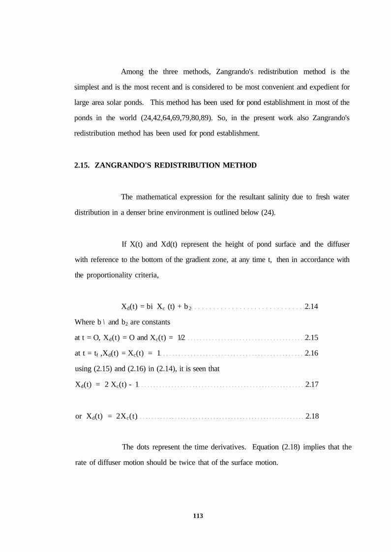
Among the three methods, Zangrando's redistribution method is the
simplest and is the most recent and is considered to be most convenient and expedient for
large area solar ponds. This method has been used for pond establishment in most of the
ponds in the world (24,42,64,69,79,80,89). So, in the present work also Zangrando's
redistribution method has been used for pond establishment.
2.15. ZANGRANDO'S REDISTRIBUTION METHOD
The mathematical expression for the resultant salinity due to fresh water
distribution in a denser brine environment is outlined below (24).
If X(t) and Xd(t) represent the height of pond surface and the diffuser
with reference to the bottom of the gradient zone, at any time t, then in accordance with
the proportionality criteria,
Xd(t) = bi Xc (t) + b 2 2.14
Where b \ and b2 are constants
at t = O, Xd(t) = O and Xc(t) = 1/2 2.15
at t = tf ,Xd(t) = Xc(t) = 1 2.16
using (2.15) and (2.16) in (2.14), it is seen that
Xd(t) = 2 Xc(t) - 1 2.17
or Xd(t) = 2Xc(t) 2.18
The dots represent the time derivatives. Equation (2.18) implies that the
rate of diffuser motion should be twice that of the surface motion.
113


Equation (2.27) gives a linear relation between the depth of the diffuser
and the salinity at that depth.
Further it is seen that if the injection diffuser is moved up with a velocity
which is twice that of the velocity of rise of water level, stepwise linear gradient
formation ie) formation of successively lower concentration layers can be obtained and
hence the NCZ can be formed.
The first step involved in adopting Zangrando's redistribution method
consists of filling the pond with brine of near saturation concentration to nearly three-
quarters full to start the process amd injecting fresh water though a properly designed flow
distributor called injection diffuser at, what will be the bottom of the gradient zone.
Because the mixture of fresh water and entrained brine is less dense than the surrounding
unmixed brine, it will rise to the surface, producting further mixing. To a first
approximation, all the water above the injection point will come to a uniform
115

concentration. As the pond fills, the point of injection should rise twice as fast as the pond
surface rises to establish a uniform gradient below the injection level. The gap separating
the injection diffuser plates is generally about 2 to 3mm and water velocities as high as
2.6m/s have been successfully used during gradient establishment (24).
2.16. STABILITY CRITERION
In a stratified solar pond, a salt gradient (or concentration gradient) has to
be established and maintained for effective (or stable) functioning of the pond. So, to
operate a solar pond in a stable manner at its desired temperature level the required
minimum concentration difference to be maintained across the NCZ has to be anlaysed.
Based on this, the required quantity of salt for pond establishment can be assessed and
these are given in the following pages.
If C1, T1, px and C2, T2, p2 are concentration, temperature, density at the
top and bottom layers of a salinity gradient solar pond, it is necessary that the lower layers
must remain denser to prevent upward convection. In such a case, for stability of the
pond, the condition to be satisfied can be represented mathematically as
116
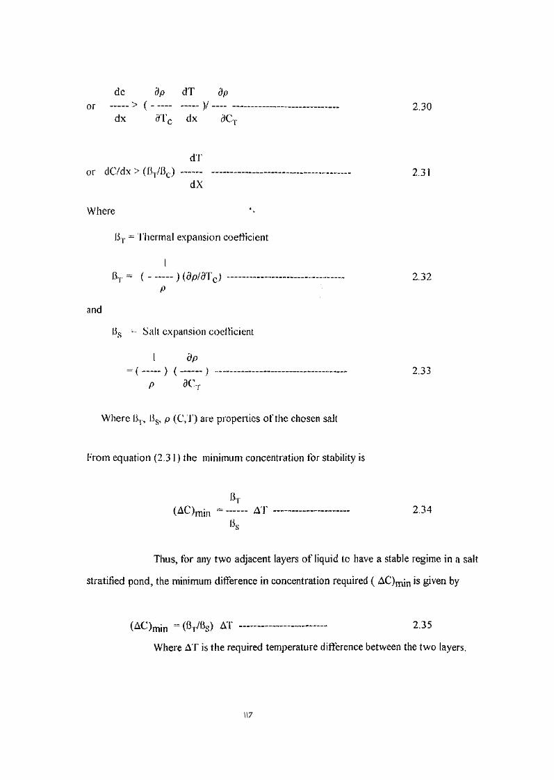
\\7

tl&

A concentration difference of 0.18 or 18% (specific gravity = 1.118) is
needed between the top and bottom layers of NCZ, for stability for maintaining the LCZ at
75°C. The top layer of NCZ has pure water. This 18% concentration difference across
the NCZ is needed for a temperature of 75°C at the bottom of NCZ. The gradient is
initially maintained at the ambient temperature of 30°C. As the temperature rises, the
concentration decreses owing to the increase in the solubility of the salt. The transport of
salt due to molecular diffusion from the bottom of the NCZ to the top of the NCZ would
rise the concentration of salt in the surface zone (ie UCZ). Owing to this also, the
concentration difference between the bottom and top layers of NCZ would decrease. So
when the gradient is established at the ambient temperature allowance must be given for
the decrease in concentration due to increase of temperature of the LCZ and due to the
diffusion of salt towards the top surface. So at the initial filling to establish the gradient, a
suitable high concentration difference has to be maintained to take care of the above
effects so that for 75°C LCZ temperature, the minimum concentration for stability
(namely 18%) could be achieved. Taking (dp/dt) as 5 X 10"4 gm/cc-°C and finding the
change of density and using the concentration versus specific gravity graph (fig..), the
initial concentraion needed would be approximated as 22%. The work of Newell et al.
(111) has shown that a surface salinity of 5% is tolerable. Gupta (110) has stated thedthe
UCZ concentration could be between 2 and 5% above which surface flushing has to be
done. Taking the extreme case of 5% concentration for the UCZ, due to salt diffusion
(from the bottom to the top), the concentration difference would decrease by 5% and
hence if 27% concentration (corresponding to a specific gravity fo 1.180) could be
maintained at the initial filling of the pond, then at 75°C LCZ temperature, the
concentration would be 18% (or slightly more) satisfying th stability condition.
119

From the above discussion it can be seen that for stable operation of the
pond the following operational procedures have to be followed.
1. The pond temperature must not be allowed to go beyond 75°C. This could be
made possible by extracting the daily collected heat.
2. To maintain the bottom concentration against diffusion and temperature effects,
periodic replenishment of salt at the LCZ has to be carried out.
3. The surface water salinity might increase due to salt transport from LCZ to UCZ
through NCZ, by molecular diffusion. Evaporation of surface water also increases
the surface salinity because of the reduction in the UCZ thickness. This increase of
salinity could reduce the minimum concentration difference to be maintained
across the NCZ depth for stability. Hence surface flushing operation has to be
resorted to so that the UCZ salinity is maintained at a low value close to 1 to 2%.
2.17. SALT REQUIREMENT
For the Pondicherry pond, from the point of view of stability, the brine
concentration of 0.27 has to be made at 30°C. The mass of salt required to be dissolved in
water in order to get the desired concentration of 0.27 Kg salt/Kg solution, at room
temperature (30°C) has been estimated and it was found to be 0.38 M.t/irA The design
thickness of the various zones of the Pondicherry solar pond are:
1. Thickness of lower convective zone = 0.90 in
2. Thickness of Non convective zone = 1.30 m
3. Thickness of Upper convective zone = 0.25 m
120
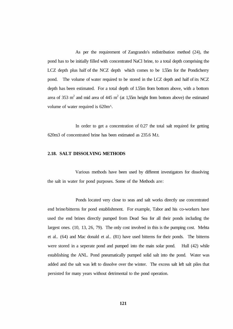
As per the requirement of Zangrando's redistribution method (24), the
pond has to be initially filled with concentrated NaCl brine, to a total depth comprising the
LCZ depth plus half of the NCZ depth which comes to be 1.55m for the Pondicherry
pond. The volume of water required to be stored in the LCZ depth and half of its NCZ
depth has been estimated. For a total depth of 1.55m from bottom above, with a bottom
area of 353 m2 and mid area of 445 m2 (at 1,55m height from bottom above) the estimated
volume of water required is 620m^.
In order to get a concentration of 0.27 the total salt required for getting
620m3 of concentrated brine has been estimated as 235.6 M.t.
2.18. SALT DISSOLVING METHODS
Various methods have been used by different investigators for dissolving
the salt in water for pond purposes. Some of the Methods are:
Ponds located very close to seas and salt works directly use concentrated
end brine/bitterns for pond establishment. For example, Tabor and his co-workers have
used the end brines directly pumped from Dead Sea for all their ponds including the
largest ones. (10, 13, 26, 79). The only cost involved in this is the pumping cost. Mehta
et al.. (64) and Mac donald et al.. (81) have used bitterns for their ponds. The bitterns
were stored in a seperate pond and pumped into the main solar pond. Hull (42) while
establishing the ANL. Pond pneumatically pumped solid salt into the pond. Water was
added and the salt was left to dissolve over the winter. The excess salt left salt piles that
persisted for many years without detrimental to the pond operation.
121

Collins (44) has reported a fast - salt dissolving technique that uses a
lixator, a downdraft salt dissolver. The dissolver consists of a pit about lm in depth, filled
with salt crystals with a sprayer on top. As the fresh water moves through the salt, it
eventually becomes saturated. Due to the filtration action of the salt stored in the lixator,
the solution coming out of the lixator is reportedly a clean, very clear saturated brine.
Direct dumping of salt into the main solar pond and allowing it to dissolve
on its own will take a long time. Further, this causes localized excess loading of the pond
floor due to the salt dumping at a few locations. Moreover, the bottom of the salt pile
will collect either decreased or nil insolation at its bottom because of the opaqueness and
reflectivity of salt pile. Moreover, if the salt crystals are directly dumped on any membrane
liner, it may get demaged because of the sharp edges of the NaCl crystals loaded on it.
Other wise they have to be powdered which involves excess labour and energy to crush
the salt into powder.
In the lixator type of salt distribution process salt has to be periodically and
gradually added into the saltpit, which may require constant feeding of salt into it, which
may require a scooper machine to do it or man power attention is consantly necessary to
load the lixator with a constant periodicity. Moreover there is a possiblity of clogging of
the silt inside the lixator which may reduce the brine discharge rate delivered into the
pond.
To overcome these problems, in the present work, the forced circulation
method has been used for the dissolution of the salt as this is simple and less time
consuming. Further the scum and other materials which float on top during mixing could
be removed and the silt which gets settled at the bottom could also be removed after
pumping the clear brine into the main tank. The same pump which is used for salt
122.
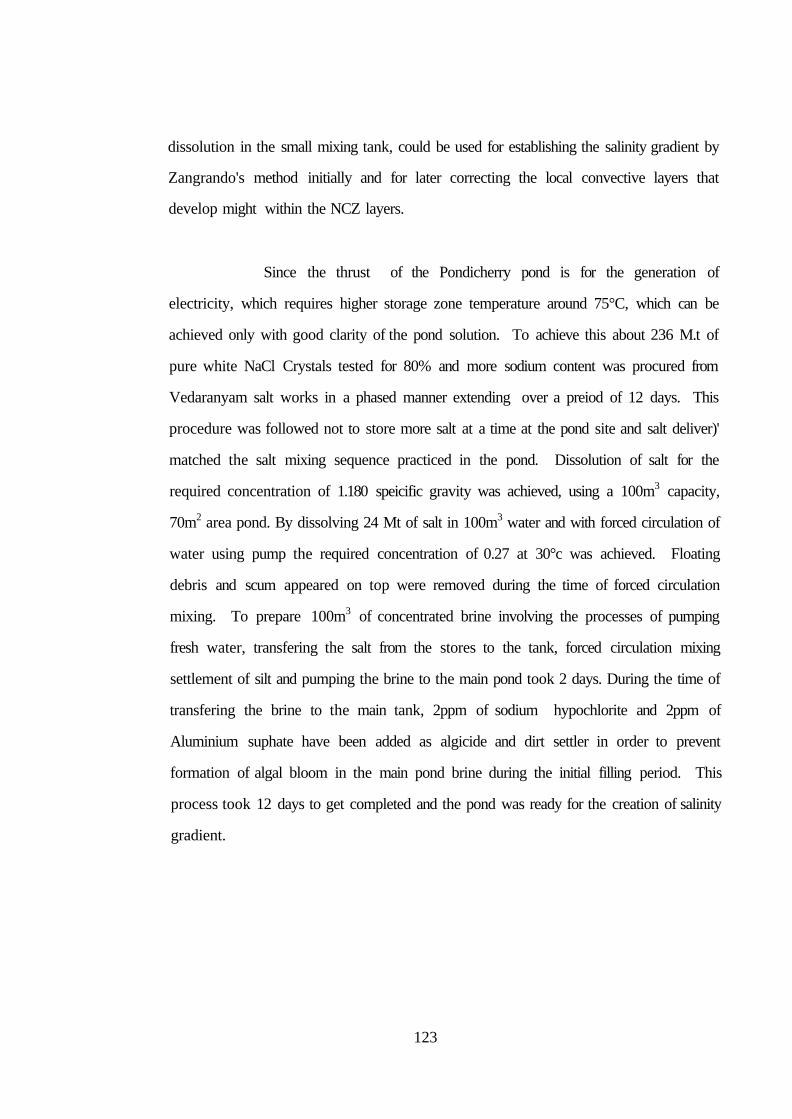
dissolution in the small mixing tank, could be used for establishing the salinity gradient by
Zangrando's method initially and for later correcting the local convective layers that
develop might within the NCZ layers.
Since the thrust of the Pondicherry pond is for the generation of
electricity, which requires higher storage zone temperature around 75°C, which can be
achieved only with good clarity of the pond solution. To achieve this about 236 M.t of
pure white NaCl Crystals tested for 80% and more sodium content was procured from
Vedaranyam salt works in a phased manner extending over a preiod of 12 days. This
procedure was followed not to store more salt at a time at the pond site and salt deliver)'
matched the salt mixing sequence practiced in the pond. Dissolution of salt for the
required concentration of 1.180 speicific gravity was achieved, using a 100m3 capacity,
70m2 area pond. By dissolving 24 Mt of salt in 100m3 water and with forced circulation of
water using pump the required concentration of 0.27 at 30°c was achieved. Floating
debris and scum appeared on top were removed during the time of forced circulation
mixing. To prepare 100m3 of concentrated brine involving the processes of pumping
fresh water, transfering the salt from the stores to the tank, forced circulation mixing
settlement of silt and pumping the brine to the main pond took 2 days. During the time of
transfering the brine to the main tank, 2ppm of sodium hypochlorite and 2ppm of
Aluminium suphate have been added as algicide and dirt settler in order to prevent
formation of algal bloom in the main pond brine during the initial filling period. This
process took 12 days to get completed and the pond was ready for the creation of salinity
gradient.
123