design and connection system siprotec 3 4 - siemens · busbar protection 7ss60 3.1 manual...
TRANSCRIPT

E50417-G1176-C132-A3
SIPROTEC
Centralized Numerical Busbar Protection7SS603.1
Manual
Introduction 1 Design and Connection System 2 Getting Started 3 Configuration 4 Functions 5 Control in Operation 6 Installation and Commissioning 7 Maintenance and Troubleshooting 8 Technical Data 9 Appendix A

Siemens Aktiengesellschaft Document No. E50417-G1176-C132-A3

37SS60 ManualE50417-G1176-C132-A3
Preface
Aim of this manual This manual describes the functions, operation, installation, and commissioning of the device. In particular, you will find:
• Description of the system configuration → Chapter 4;
• Description of the system functions and setting possibilities → Chapter 5;
• Hints on control during operation → Chapter 6;
• Instructions for installation and commissioning → Chapter 7;
• List of the technical data → Chapter 9;
• Summary of the most significant data for the experienced user in the Appendix.
Target audience Protection engineers, commissioners, persons who are involved in setting, testing and maintenance of protection, automation, and control devices, as well as operation per-sonnel in electrical plants and power stations.
Validity of this manual
This manual is valid for: SIPROTEC 7SS60; firmware version 3.1.
Indication of Conformity
This product complies with the directive of the Council of the European Communities on the approximation of the laws of the Member States relating to electromagnetic compatibility (EMC Council Directive 89/336/EEC) and concerning electrical equip-ment for use within specified voltage limits (Low-voltage directive 73/23 EEC).
Conformity is proved by tests conducted by Siemens AG in accordance with Article 10 of the Council Directive in agreement with the generic standards EN 50 081 and EN 50 082 (for EMC directive) and the standards EN 60 255-6 (for low-voltage directive).
The device is designed in accordance with the international standards of IEC 255 and the German standards DIN 57 435 part 303 (corresponding to VDE 0435 part 303).
Additional support For any questions concerning your SIPROTEC system, please contact your Siemens representative.
Training courses Individual course offers may be found in our Training Catalog, or questions can be di-rected to our training centre.
Preface
4 7SS60 ManualE50417-G1176-C132-A3
Instructions and warnings
The warnings and notes contained in this manual serve for your own safety and for an appropriate lifetime of the device. Please observe them!
The following terms and definitions are used:
DANGER indicates that death, severe personal injury or substantial property damage will result if proper precautions are not taken.
Warning indicates that death, severe personal injury or substantial property damage can result if proper precautions are not taken.
Caution indicates that minor personal injury or property damage can result if proper precau-tions are not taken. This is especially valid for damage on or in the device itself and consequential damage thereof.
Note indicates information about the device or respective part of the instruction manual which is essential to highlight.
Warning! Hazardous voltages are present in this electrical equipment during operation. Non–observance of the safety rules can result in severe personal injury or property dam-age.
Only qualified personnel shall work on and around this equipment after becoming thor-oughly familiar with all warnings and safety notices of this manual as well as with the applicable safety regulations.
The successful and safe operation of this device is dependent on proper handling, in-stallation, operation, and maintenance by qualified personnel under observance of all warnings and hints contained in this manual.
In particular the general erection and safety regulations (e.g. IEC, DIN, VDE, EN or other national and international standards) regarding the correct use of hoisting gear must be observed. Non–observance can result in death, personal injury or substantial property damage.
QUALIFIED PERSONNEL
For the purpose of this instruction manual and product labels, a qualified person is one who is familiar with the installation, construction and operation of the equipment and the hazards involved. In addition, he or she has the following qualifications:
• Is trained and authorized to energize, de-energize, clear, ground and tag circuits and equipment in accordance with established safety practices.
• Is trained in the proper care and use of protective equipment in accordance with es-tablished safety practices.
• Is trained in rendering first aid.

Preface
57SS60 ManualE50417-G1176-C132-A3
Typographical and symbol conventions
The following text formats are used when literal information from the device or to the device appear in the text flow:
Parameter names, i.e. designators of configuration or function parameters, which may appear word-for-word in the display of the device or on the screen of a personal computer (with DIGSI), are marked in bold letters of a monospace type style.
Parameter options, i.e. possible settings of text parameters, which may appear word-for-word in the display of the device or on the screen of a personal computer (with DIGSI), are written in italic style, additionally. This applies also for options in menus.
Annunciations, i.e. designators for information, which may be output by the relay or required from other devices or from the switch gear, are marked in a monospace type style in quotes.
Deviations may be permitted in drawings when the type of designator can be obviously derived from the illustration.
and the possible states On and Off
UL1–L2
Earth fault Internal logical input signal of the device
Earth fault Internal logical output signal of the device
Incoming internal signal of an analog magnitude
>ReleaseExternal binary input signal with function number FNo
Dev. TRIP External binary output signal with function number FNo
On
Off
1234 FUNCTION
Parameter addressParameter name
Parameter states
Example of a parameter switch FUNCTION with the address 1234
(binary input, input annunciation)
(device annunciation)
FNo
FNo
The other symbols used are mainly taken from the standards IEC 60 617–12 and IEC 60 617–13, or derived from them.
Disclaimer of liabilityAlthough we have carefully checked the contents of this publication for conformity with the hardware and software described, we cannot guarantee complete conformity since errors cannot be excluded. The information provided in this manual is checked at regular intervals and any corrections which might be-come necessary are included in the next releases. Any suggestions for improvement are welcome.
The contents of this manual is subject to change without prior notice. Release 3.11.01
CopyrightCopyright © Siemens AG 2011 All Rights ReservedThis document shall not be transmitted or reproduced, nor shall its contents be exploited or disclosed to third persons without prior written consent from Siemens. Infringements shall entitle to damage claims. All rights reserved, in particular in case of a patent grant or utility model registration.
Registered Trademarks SIPROTEC, SINAUT, SICAM und DIGSI are registered trademarks of SIEMENS AG. All other product and brand names in this manual may be trademarks, the use of which by third persons for their purposes may in-fringe the rights of their respective owners.

Preface
6 7SS60 ManualE50417-G1176-C132-A3
77SS60 ManualE50417-G1176-C132-A3
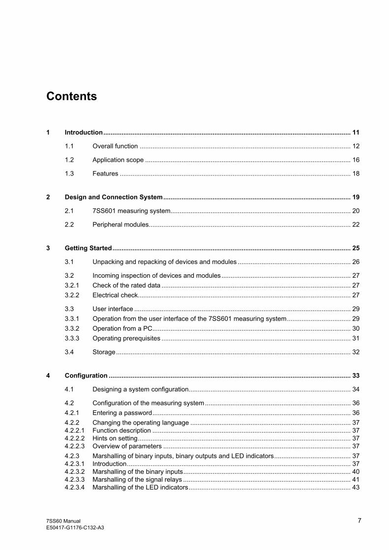
Contents
1 Introduction........................................................................................................................................ 11
1.1 Overall function .................................................................................................................... 12
1.2 Application scope ................................................................................................................. 16
1.3 Features ............................................................................................................................... 18
2 Design and Connection System....................................................................................................... 19
2.1 7SS601 measuring system................................................................................................... 20
2.2 Peripheral modules............................................................................................................... 22
3 Getting Started................................................................................................................................... 25
3.1 Unpacking and repacking of devices and modules .............................................................. 26
3.2 Incoming inspection of devices and modules....................................................................... 273.2.1 Check of the rated data ........................................................................................................ 273.2.2 Electrical check..................................................................................................................... 27
3.3 User interface ....................................................................................................................... 293.3.1 Operation from the user interface of the 7SS601 measuring system................................... 293.3.2 Operation from a PC............................................................................................................. 303.3.3 Operating prerequisites ........................................................................................................ 31
3.4 Storage................................................................................................................................. 32
4 Configuration ..................................................................................................................................... 33
4.1 Designing a system configuration......................................................................................... 34
4.2 Configuration of the measuring system................................................................................ 364.2.1 Entering a password............................................................................................................. 364.2.2 Changing the operating language ........................................................................................ 374.2.2.1 Function description ............................................................................................................. 374.2.2.2 Hints on setting..................................................................................................................... 374.2.2.3 Overview of parameters ....................................................................................................... 374.2.3 Marshalling of binary inputs, binary outputs and LED indicators.......................................... 374.2.3.1 Introduction........................................................................................................................... 374.2.3.2 Marshalling of the binary inputs............................................................................................ 404.2.3.3 Marshalling of the signal relays ............................................................................................ 414.2.3.4 Marshalling of the LED indicators......................................................................................... 43

Contents
8 7SS60 ManualE50417-G1176-C132-A3
4.2.3.5 Marshalling of the command (trip) relays.............................................................................. 444.2.4 Serial interface...................................................................................................................... 454.2.4.1 Function description.............................................................................................................. 454.2.4.2 Hints on setting..................................................................................................................... 454.2.4.3 Overview of parameters........................................................................................................ 464.2.5 Setting of date and time........................................................................................................ 474.2.5.1 Function description.............................................................................................................. 474.2.5.2 Hints on setting..................................................................................................................... 47
5 Functions............................................................................................................................................ 49
5.1 Measurement method........................................................................................................... 50
5.2 Formation of measuring currents from the transformer currents .......................................... 555.2.1 Summation current transformer methode ............................................................................. 565.2.1.1 Normal earth current sensitivity ............................................................................................ 575.2.1.2 Increased earth current sensitivity ........................................................................................ 605.2.2 Phase-selective measurement ............................................................................................. 635.2.3 Matching transformers .......................................................................................................... 64
5.3 Power system and switchgear data - Block 01..................................................................... 665.3.1 Function description.............................................................................................................. 665.3.2 Hints on setting..................................................................................................................... 675.3.3 Overview of parameters........................................................................................................ 675.3.4 Annunciations ....................................................................................................................... 67
5.4 Busbar protection.................................................................................................................. 685.4.1 Function description.............................................................................................................. 685.4.2 Hints on setting..................................................................................................................... 705.4.3 Overview of parameters........................................................................................................ 715.4.4 Annunciations ....................................................................................................................... 71
5.5 Differential current supervision - Block 13 ............................................................................ 725.5.1 Function description.............................................................................................................. 725.5.2 Hints on setting..................................................................................................................... 725.5.3 Overview of parameters........................................................................................................ 735.5.4 Annunciations ....................................................................................................................... 73
5.6 Fault recording - Block 74..................................................................................................... 745.6.1 Function description.............................................................................................................. 745.6.2 Hints on setting..................................................................................................................... 745.6.3 Overview of parameters........................................................................................................ 74
6 Control in Operation .......................................................................................................................... 75
6.1 Read-out of information ........................................................................................................ 766.1.1 Output of annunciations and measured values .................................................................... 76
6.2 Read out of the date and time ........................................................................................... 79
6.3 Testing the status of the binary inputs/outputs .............................................................. 79
Contents
97SS60 ManualE50417-G1176-C132-A3
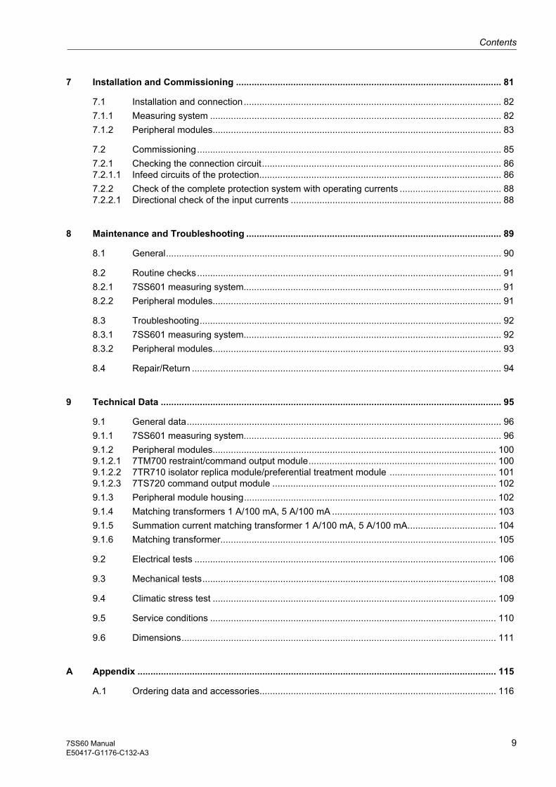
7 Installation and Commissioning ...................................................................................................... 81
7.1 Installation and connection................................................................................................... 827.1.1 Measuring system ................................................................................................................ 827.1.2 Peripheral modules............................................................................................................... 83
7.2 Commissioning..................................................................................................................... 857.2.1 Checking the connection circuit............................................................................................ 867.2.1.1 Infeed circuits of the protection............................................................................................. 867.2.2 Check of the complete protection system with operating currents ....................................... 887.2.2.1 Directional check of the input currents ................................................................................. 88
8 Maintenance and Troubleshooting .................................................................................................. 89
8.1 General................................................................................................................................. 90
8.2 Routine checks..................................................................................................................... 918.2.1 7SS601 measuring system................................................................................................... 918.2.2 Peripheral modules............................................................................................................... 91
8.3 Troubleshooting.................................................................................................................... 928.3.1 7SS601 measuring system................................................................................................... 928.3.2 Peripheral modules............................................................................................................... 93
8.4 Repair/Return ....................................................................................................................... 94
9 Technical Data ................................................................................................................................... 95
9.1 General data......................................................................................................................... 969.1.1 7SS601 measuring system................................................................................................... 969.1.2 Peripheral modules............................................................................................................. 1009.1.2.1 7TM700 restraint/command output module........................................................................ 1009.1.2.2 7TR710 isolator replica module/preferential treatment module ......................................... 1019.1.2.3 7TS720 command output module ...................................................................................... 1029.1.3 Peripheral module housing................................................................................................. 1029.1.4 Matching transformers 1 A/100 mA, 5 A/100 mA ............................................................... 1039.1.5 Summation current matching transformer 1 A/100 mA, 5 A/100 mA.................................. 1049.1.6 Matching transformer.......................................................................................................... 105
9.2 Electrical tests .................................................................................................................... 106
9.3 Mechanical tests................................................................................................................. 108
9.4 Climatic stress test ............................................................................................................. 109
9.5 Service conditions .............................................................................................................. 110
9.6 Dimensions......................................................................................................................... 111
A Appendix .......................................................................................................................................... 115
A.1 Ordering data and accessories........................................................................................... 116

Contents
10 7SS60 ManualE50417-G1176-C132-A3
A.2 Block diagram - Measuring system..................................................................................... 119
A.3 Block diagrams - Peripheral modules ................................................................................. 120
A.4 Jumper settings for the measuring system......................................................................... 123
A.5 Jumper settings for the peripheral modules........................................................................ 125
A.6 Operating tree..................................................................................................................... 128
A.7 Overview of parameters .................................................................................................... 133
A.8 List of information .............................................................................................................. 134

117SS60 ManualE50417-G1176-C132-A3
Introduction 1The SIPROTEC 7SS60 device is introduced in this chapter. An overview of the appli-cation and characteristics of the 7SS60 is given.
1.1 Overall function 12
1.2 Application scope 16
1.3 Features 18

Introduction
12 7SS60 ManualE50417-G1176-C132-A3
1.1 Overall function
Measuring principle
The main function of the 7SS60 protection system is a busbar protection that operates with the differential current measuring principle. The algorithm of the 7SS60 relies on Kirchhoff's current law, which states that in fault-free condition the vectorial sum ΔI flowing into a closed busbar section must be zero. This summated current will be re-ferred to in this chapter as differential current Id.
Restraint Some slight deviations from this law may be caused by current transformer errors, in-accuracies in the matching of the transformation ratios and measuring inaccuracies. Further errors, which may be due, for instance, to transformer saturation in case of high-current external short-circuits, are counteracted by a load-dependent supple-mentary restraint. From the load condition the restraint current IR is derived. This re-straint current is formed as the summated magnitudes of all currents in the peripheral module 7TM700.
Detection of measured values
The differential and the restraint current are fed into the 7SS601 measuring system. In systems with multiple busbars or sectionalized busbars, each selective section uses one 7SS601 measuring system (variant with summation current transformer) or three measuring systems (phase-selective measurement). The correct allocation of the feeder currents to the appropriate 7SS601 measuring system is ensured by the pe-ripheral module 7TR710 (preferential treatment/isolator replica).
Pick-up characteristic
The characteristic can be set in the parameters for Id> (pick-up value) and for the k factor, which considers the linear and non-linear current transformer errors. The set-ting for the pick-up value must be chosen according to the smallest fault current to be expected. Differential currents above the set characteristic lead to tripping. The threshold for the differential current supervision is set in the parameter ID thr.
Id>
0
Differential current Id
Restraint current IR
ID thr
k = 0.80
k = 0,25
Pick-upcharact-eristics
Tripping zone
Restraintzone
Normal load line
.
.
.
.
.
.
.
.
Figure 1-1 Characteristic of the 7SS601 measuring system
Selective tripping, isolator replica
If a measuring system 7SS601 recognizes a tripping condition, the circuit breakers of the involved feeders must be tripped. This requires an isolator replica which is gener-ated on the module 7TR710 (isolator replica/preferential treatment) from the position of the isolators. Basing on this isolator replica a TRIP command of a measuring sys-tem is distributed to the circuit breakers.

Introduction
137SS60 ManualE50417-G1176-C132-A3
Functional components
The 7SS60 digital busbar protection has two separate functional parts. One part is the 7SS601 measuring system. The measuring system detects and processes the mea-sured values. It evaluates the restraint current IR and the differential current Id and makes a tripping decision where required. The other part of the system, which will be referred to as peripheral system, has the task of summating the feeder currents and feeding the current sum into the measured value detection system. The current sum-mation takes into account the switchgear status of the station.
If selective protection is desired for each phase, each phase is allocated its own mea-suring system. Otherwise, the three phase currents are combined in a summation cur-rent transformer, and the result processed. In that case only one measuring system is required.
If a busbar is divided into two sections by a sectionalizing isolator or a bus coupler, each section must have its own measuring system. Accordingly, six measuring sys-tems are required for the phase-selective protection.
7SS601 measuring system
The 7SS601 measuring system can detect one alternating current Id and one pulsat-ing direct current IR. The measuring inputs are galvanically isolated from the electronic equipment by a current transformer or an optocoupler.
3 binary inputs are provided for the detection of external binary signals.
The system has 2 command relays with supervision. Command relay 1 consists of 2 relays connected in parallel. This relay cannot be marshalled; the function BP Trip (FNo. 7914) is permanently allocated to it. Command relay 2 is available for having command functions marshalled to it. All command relays have a NO contact.
It has also 3 signal relays with changeover contacts, one of which is used for output of the device blocked annunciation. The relay functionality (NC or NO) can be selected by a jumper setting. The module is equipped with a serial RS485 interface. The con-verter for the auxiliary power supply is integrated in the module.
Peripheral system Depending on the type and size of the systems that are to be protected by the 7SS60 busbar protection, different types and numbers of peripheral modules are needed. The peripheral modules are installed in a 7XP204 housing; the number of housings re-quired is determined by the number of modules used. Each 7XP204 housing can hold up to 4 peripheral modules.
The following modules are available for the different functions:
• Restraint/command output module 7TM700
• Preferential treatment/isolator replica module 7TR710
• Command output module 7TS720
Restraint/command output module 7TM700
This module comprises 5 units for the formation of restraint currents. It has also 5 in-dependent TRIP command relays with 2 NO contacts each for multiplication of TRIP commands generated by the 7SS601 measuring system.
The secondary current from the main current transformer of a feeder is normalized to 100 mA by a matching or summation current transformer and fed into the Id summa-tion path of the associated measuring system. The summation current Id is thus equiv-alent to the vectorial addition of all feeder currents. Beside Id, the measuring system requires a restraint value, which is formed by adding up the magnitudes of all currents. The restraint units are used to form the current magnitudes. They rectify the feeder currents and add them up in the IR summation path.

Introduction
14 7SS60 ManualE50417-G1176-C132-A3
Isolator replica module/preferential treatment module
This module can be used to implement 2 different functions which will be presented in the following.
Isolator replica The isolator replica function detects the status of 2 isolators.
It allows e.g. to recognize the status of both isolators in a double busbar system. The isolator status determines the allocation of the feeder currents to the appropriate mea-suring system. It also ensures the stability and greatest possible selectivity of the pro-tection system during dynamic processes such as switching operations.
Preferential treatment
If, during a changeover of a feeder in a double busbar system, both isolators of a feed-er are closed for a short time, no selective protection of the two busbars is possible. The same is true for busbar sections that are connected by closing a sectionalizing isolator. Whereas each of the two sections has so far been protected by its own mea-suring system, the protection function is assumed by only one measuring system after connecting the two sections. This is referred to as preferential treatment.
As several relays or modules may be involved in the switching action, there may be an undefined allocation of the differential and restraint currents to the measuring sys-tems during a few milliseconds caused by different relay switching times.
The blocking pulse required for system stability is generated automatically on the module within the corresponding time.
Also an auxiliary relay is included with two changeover contacts.
Command output module 7TS720
This module comprises 8 independent command relays with 2 NO contacts each for multiplication of the TRIP command generated by the 7SS601 measuring system.
It is necessary to multiply the TRIP command if the two NO contacts of the 7TR710 modules are not sufficient for command output to the circuit breakers. The measuring system initiates the TRIP command first through a NO contact. In the simplest case, an auxiliary voltage is fed directly from this contact onto the 7TS720 module, where it causes one or more relay coils to pick up.

Introduction
157SS60 ManualE50417-G1176-C132-A3
Transformers The differential current input Id of the 7SS60 is designed for 1 x In = 100 mA. There-fore, a transformer must be provided between the 7SS60 and the main current trans-former. In phase-selective protection systems, matching transformers are used; oth-erwise there will be summation current transformers.
Figure 1-2 Principle diagram of transformers in the 7SS60 (one phase of a phase-selective protection system)
Wiring The 7SS60 busbar protection system is suited for a large variety of power systems, from single busbar configurations without sectionalizing isolators to double busbars with sectionalizing isolators and transversal couplers. The summation currents Id and IR are distributed among the measuring systems by relay modules that provide for connection of nearly all relay contacts to connecting points. This provides for a high degree of flexibility of the modules. One configuration task is to design the wiring be-tween the modules, the modules and the 7SS601 measuring systems, and to the pri-mary equipment, in accordance with the desired function.
Mounting The 7SS60 busbar protection system is made up of individual components which are then mounted station-specifically in cubicles or mounting panels.

Introduction
16 7SS60 ManualE50417-G1176-C132-A3
1.2 Application scope
The 7SS60 busbar protection is an easily settable numerical differential current pro-tection for busbars.
It is suitable for all voltage levels and can be adapted to a large variety of busbar con-figurations. The components available are designed in particular for:
• 11/2 - circuit breaker systems
• single busbars (with/without sectionalizing isolators)
• double busbars with sectionalizing isolators, longitudinal couplers and transversal couplers
These types of systems are shown in the following figures.
Single-phase measurement can be achieved by using external summation current transformers. The use of matching transformers allows phase-selective measure-ment.
For extra security, an additional measuring system (check zone) can be implemented.
The busbar protection system is designed to be the successor of the 7SS1 static bus-bar protection. Where it replaces this system, the existing matching transformers and summation current transformers can be used with the new system as well.
BB1
BB2
Figure 1-3 11/2 - circuit breaker system

BB1A BB1B
Introduction
177SS60 ManualE50417-G1176-C132-A3
Figure 1-4 Single busbar with sectionalizing isolator
BB1A BB1B
BB2A BB2B
Figure 1-5 Double busbar with couplers and sectionalizing isolator

Introduction
18 7SS60 ManualE50417-G1176-C132-A3
1.3 Features
The 7SS60 busbar protection has the following features:
• Busbar protection operating on the differential current principle; one measuring sys-tem per busbar section or, depending on the configuration, per phase and zone; op-tionally one additional measuring system for the check zone (isolator-independent measuring system)
• Full galvanic and interference-immune isolation between the internal processing circuits and the measuring, control and supply circuits of the system by screened measuring transducers, binary input and output modules and DC voltage convert-ers
• Fully digital measured value processing and protection functions, from the sampling and digitizing of the measured values to the TRIP decisions for the circuit breakers
• High degree of security against overfunction, and detection of external faults even with unfavourable transformer configuration
• Differential current supervision of transformer circuits, with blocking option for TRIP command
• Blocking of TRIP command possible by fast binary input
• Low demands on current transformers
• Numerical system with powerful 16-bit microprocessor system
• Easy menu-guided operation via integrated keypad and display panel or by con-nected PC using DIGSI
• Storage of fault annunciations and of instantaneous values for fault recording
• Continuous monitoring of the hardware and software of the 7SS601 measuring sys-tem, as well as of the primary current transformers and their supply conductors
• Integrated commissioning aids

197SS60 ManualE50417-G1176-C132-A3
Design and Connection System 2This chapter describes the design and the connection system of the 7SS60. You will find information on the available housing variants and on the types of connections used.
This chapter also specifies recommended and reliable wiring data as well as suitable accessories and tools.
2.1 7SS601 measuring system 20
2.2 Peripheral modules 22

Design and Connection System
20 7SS60 ManualE50417-G1176-C132-A3
2.1 7SS601 measuring system
Housing All protection functions including dc/dc converter are accommodated on a printed cir-cuit board of double Europe format. This p.c.b. forms, complemented by a guide plate, a multi-pin terminal module (p.c.b. side) and a front unit, the plug-in module which is mounted in a 7XP20 housing. The inner part of the housing is free from enamel and thus functions as a large contact plane and shield with solid electrical conductivity and mates with the earthing plates of the module. Connection to earth is made before the plugs make contact. An earthing area marked with an earth symbol has been provided at the housing rear. At this area an earthing strip must be connected with two earthing screws in order to ensure solid low-impedance earthing.
SIEMENS
1234
Service/BetriebBlocked/Störung
Reset
+ –
Y/J
E
N
Busbar ProtectionSammelschinenschutzIN = 1,9/100 mAfN = 50, 60 HzUH = 24, 48 V DCDiagr.: C53000-B1174-C135-*
7SS6010-2EA00-0AA0/BBF.-Nr.: BF 30.10.2000
2 2,8 UH
RS485;5 , III
!
1 2
3 4
5 6
31
7
29
27
25
23
21
19
17
15
13
11
9
30
28
26
24
22
20
18
16
14
12
10
8
Figure 2-1 Front view (left) and rear view (right) of the 7SS601 measuring system
The terminal allocation of the measurement system is shown in Section A.2.

Design and Connection System
217SS60 ManualE50417-G1176-C132-A3
Connection systemCurrent connections (terminals 1 to 6)
Screw terminals (ring-type cable lug) for bolts of 6 mm
max. outside diameter 13 mm
Type e.g. PDIG of Messrs. Tyco Electronics AMP
for conductor cross-sections of 2.7 to 6.6 mm AWG 12 to 10
in parallel double leaf-spring-crimp contact for conductor cross-sections of
2.5 to 4.0 mm AWG 13 to 11
max. tightening torque 3.5 Nm
Control connections (terminals 7 to 31)
Screw terminals (ring-type cable lug) for bolts of 4 mm
max. outside diameter 9 mm
Type e.g. PDIG of Messrs. Tyco Electronics AMP
for conductor cross-sections of 1.0 to 2.6 mm AWG 17 to 13
in parallel double leaf-spring-crimp contact for conductor cross-sections of
0.5 to 2.5 mmAWG 20 to 13
max. tightening torque 1.8 Nm

Design and Connection System
22 7SS60 ManualE50417-G1176-C132-A3
2.2 Peripheral modules
Housing The peripheral modules are accommodated in one or more 7XP204 housings. One housing can hold up to 4 peripheral modules in any order.
Two angle brackets are required to fit the housing into a frame or cabinet.You can look up the order number in chapter A.1 in the appendix.
The housing has a labelling strip inserted on its front for identification of the modules contained in it.
The rear plate has cutouts for the connectors. The cutouts provided are sufficient for the maximum degree of expansion. If the housing contains less modules, the cutouts that are not required are closed by metal blanking plates.
An earthing area marked with an earth symbol has been provided at the housing rear. At this area an earthing strip must be connected with two earthing screws in order to ensure solid low-impedance earthing.
In addition, the housing bears a rating sticker with basic information.
SIEMENS SIPROTEC
7SS60
A
B
C
D
Pos. Module40
21
20
1
40
21
20
1
40
21
20
1
40
21
20
1
40
21
20
1
40
21
20
1
40
21
20
1
40
21
20
1
ABCD
X1X1 X1 X1
X2X2 X2 X2
Figure 2-2 Front view (left) and rear view (right) of the 7XP204 housing for peripheral modules
The connector allocation depends on the type of peripheral module and is shown in section A.2.

Design and Connection System
237SS60 ManualE50417-G1176-C132-A3
Connection system Each peripheral module is delivered with 8 plug-on connectors with screw terminals. Further plug-on connectors can be ordered as spare parts, see chapter A.1.
Connectors with screw terminals
Type COMBICON systemof Messrs. PHOENIX CONTACTFront-MSTB 2,5/10-ST
for conductor cross-sections of
Multiple conductor connection (2 conductors of same cross-section)
0.2 to 2.5 mm2 (rigid and flexible)AWG 24 to 120.25 to 2.5 mm2 (with end sleeve) 0.2 to 1.0 mm2 (rigid)0.2 to 1.5 mm2 (flexible)0.25 to 1.0 mm2 (rigid with end sleeve, without plastic collar)0.5 to 1.5 mm2 (flexible with TWIN end sleeve with plastic collar)
Stripping length 10 mm
Recommended tightening torque 0.5 to 0.6 Nm
Mounting slots peripheral modules
Slot A Slot B
Slot CSlot D
Figure 2-3 Mounting slots for the peripheral modules in the 7XP204 housing (front view)
The module guiding grooves are marked.

Design and Connection System
24 7SS60 ManualE50417-G1176-C132-A3

257SS60 ManualE50417-G1176-C132-A3
Getting Started 3This chapter describes the first steps that you should take after receiving your SIPROTEC 7SS60 devices and modules. After unpacking, please check whether the version and rated data match your requirements.
For an electrical check, you can navigate in the user interface without any measured values. You can also connect the measuring system 7SS601 to a PC and operate it from the computer using the DIGSI communication software.
In the last section you will find hints on what to observe for a long-term storage of the system.
3.1 Unpacking and repacking of devices and modules 26
3.2 Incoming inspection of devices and modules 27
3.3 User interface 29
3.4 Storage 32

Getting Started
26 7SS60 ManualE50417-G1176-C132-A3
3.1 Unpacking and repacking of devices and modules
The devices and modules are packed in the factory such that the requirements of IEC 60255-21 are fulfilled.
Unpacking and repacking must be performed with the usual care, without force and only with the aid of suitable tools. The devices and modules must be visually checked to ensure that they have not been mechanically damaged.
Please observe the instruction leaflet and any other documentation that may be part of the delivery.
The shipping packaging can be reused in the same manner for further shipment. If oth-er packaging is used, shock requirements under IEC 60 255-21-1 Class 2 and IEC 60 255-21-2 Class 1 must be met.
The devices and modules should be in the final operating area for a minimum of two hours before the power source is first applied. This time allows the device to attain temperature equilibrium, and prevents dampness and condensation.

Getting Started
277SS60 ManualE50417-G1176-C132-A3
3.2 Incoming inspection of devices and modules
3.2.1 Check of the rated data
Ordering code First of all, check the complete ordering code (MLFB) of the units and modules to en-sure that the versions delivered comply with the required rated data and functions, and that the necessary and desired accessories are complete. The complete ordering code of the devices and modules can be found on their rating stickers.
The 7SS601 measuring system has its rating sticker on the front of the housing.
The peripheral modules come with a rating sticker that is placed the housing in which the peripheral module is installed during assembly of the system.
The ordering code and the meaning of its digits are shown in Table A-1. The most im-portant point is the matching of the rated device data to the station ratings. This infor-mation is found on the rating sticker. The measuring system is delivered with the bi-nary inputs set in such a way that a dc voltage of the same level as the auxiliary supply voltage is required for their activation. The jumper settings are listed in Appendix A.4. The delivery status of the peripheral modules is shown in Appendix A.5.
3.2.2 Electrical check
The operating conditions must accord with VDE 0100 and VDE 0105 Part 1.
The unit should be in the final operating area for a minimum of two hours before the power source is first applied. This time allows the device to attain temperature equilib-rium, and prevents dampness and condensation.
Warning! Some of the following checks are carried out in presence of hazardous voltages. They must only be performed by qualified personnel which is thoroughly familiar with all safety regulations and precautionary measures and pays due attention to them.
For a first electrical check of the system, it is sufficient to ensure a reliable earthing and to connect the auxiliary supply voltage:
7SS60 overall system
Connect an auxiliary supply voltage of the correct level and polarity to the inputs of the unit via a switch or m.c.b. Please observe the connection diagrams in Appendix A.2 and A.3.
Close the protective switch or m.c.b. to apply the auxiliary supply voltage.

Getting Started
28 7SS60 ManualE50417-G1176-C132-A3
7SS601 measuring system
Connect the earth of the device to the protective earth of the location. Units for cu-bicle or panel flush mounting have the earthing screws on their back.
The green Service/Betrieb LED on the front plate must light after at most 0.5 s, and the red Blocked/Störung LED must go off after at most 10 s.
After at most 15 s the start-up messages indicating the ordering code and the firm-ware version must disappear from the display. Instead, the measured values of the differential current Id and the restraint current IR should appear. Depending on the preset marshalling, some of the LEDs may light already.

Getting Started
297SS60 ManualE50417-G1176-C132-A3
3.3 User interface
3.3.1 Operation from the user interface of the 7SS601 measuring system
Digital protection and automation devices are operated through the integrated keypad and the display panel in a device-user dialog. All parameters required for operation can be entered and all the information can be read out from here. It is also possible to operate the system from a PC that is connected to the serial interface.
Membrane keypad/ display panel
Figure 3-1 shows a front view of the 7SS601 measuring system.
SIEMENS
1234
Service/BetriebBlocked/Störung
Reset
+ –
Y/J
E
N
Busbar ProtectionSammelschinenschutzIN = 1,9/100 mAfN = 50, 60 HzUH = 24, 48 V DCDiagr.: C53000-B1174-C135-*
7SS6010-2EA00-0AA0/BBF.-Nr.: BF 30.10.2000
2 2,8 UH
RS485;5 , III
!
“Ready” LED (greed)
“Blocked” LED (red)
LEDs 1 to 4 (red), marshallable
2-line display panel (LCD)
Keypad with control
with 8 digits characters each
and function keys
Figure 3-1 Front view of the 7SS601 measuring system with keypad and display panel
An LC display with 2 lines of 8 characters each is provided for display.
Parameters are displayed with a 2-digit number in the upper display line on the left. This number represents the address block.
The keypad comprises 9 keys, including a YES and a NO key and control keys that are used to navigate through the hierarchically structured operating menu tree. The keys have the following meanings:
Keys for changing numerical values and predefined user options:
+ Increases the set value
– Decreases the set value

Getting Started
30 7SS60 ManualE50417-G1176-C132-A3
YES/NO keys:
Y/J YES key: Operator confirms the displayed question
N NO key: Operator negates the displayed question. This key is also used to reset memorized LED indications and fault alarms.
Keys for scrolling in the display:
Forward scrolling: the display shows the next operating position of the same operation level
Backward scrolling: the display shows the previous operating position of the same operation level
Forward scrolling to the next operation level: the display shows the associated operating object in the next operation level
Backward scrolling to the previous operation level: the displays shows the associated operating object in the previous operation level
Confirmation keys:
E ENTER key: All changes of the display made by numerical entries or by pressing the Y/J and N keys must be confirmed with the ENTER key to be accepted by the device. The ENTER key is also used to acknowledge messages from the device if an entry is rejected; in that case a new entry must be made and confirmed with the ENTER key.
By depressing the N key, spontaneous fault alarms are reset and the quiescent-state indications reactivated. The marshallable LEDs on the front light up during the reset, so that the proper functioning of the LEDs can be checked as well.
3.3.2 Operation from a PC
You can make settings, start test procedures and read out data from a PC with the DIGSI communication software in the same way as with the integrated keypad, with the additional comfort of a monitor display and operator guidance through the menu.
All data can be stored on data carrier and read in from there (e.g. during configuration). If a printer is connected, the data can be printed out for documentation.
When operating the firmware from a PC, please observe the relevant operating man-uals. The DIGSI communication software is suited for processing protection data.

Getting Started
317SS60 ManualE50417-G1176-C132-A3
3.3.3 Operating prerequisites
For most operational functions, the input of a password is necessary. This applies to all entries via operator keypad or user interface which concern the functions of the 7SS601 measuring system, such as:
• setting of operational parameters (thresholds, functions),
• marshalling of command relays, alarms, binary inputs, LED indications,
• system design parameters for operating language, interface and device configura-tion,
• starting of test procedures.
The password is not required for readout of annunciations, operational data, fault data and setting values.
The preparatory instructions in subsection 4.2.1 describe in detail how to enter the password and to adapt the PC interface.
Getting Started
32 7SS60 ManualE50417-G1176-C132-A3
3.4 Storage
If units or modules are to be stored, the following storage conditions should be ob-served:
SIPROTEC devices and modules should be stored in dry and clean rooms. For stor-age of devices, peripheral modules or related spare modules the applicable tempera-ture range is between – 25 °C and +55 °C (refer also to section 9.1 under Technical Data).
It is recommended to limit the temperature range for storage to values between +10 °C and +35 °C in order to avoid early ageing of the electrolytic capacitors in the power supplies.
The relative humidity must not cause condensation or ice.
Furthermore it is recommended to connect the devices and modules to auxiliary volt-age for about 1 or 2 days every two years, so that the electrolytic capacitors in the power supplies are formatted. The same procedure should be followed before install-ing these devices. In case of extreme climatic conditions (tropical), this pre-heats the device and avoids condensation.
The units and modules should be in the final operating area for a minimum of two hours before the power source is first applied. This time allows the device to attain temperature equilibrium, and prevents dampness and condensation.

337SS60 ManualE50417-G1176-C132-A3
Configuration 4The configuration of the SIPROTEC 7SS60 device comprises two parts.
The first part includes the selection and interconnection of the necessary components according to the station configuration. The system configuration is dealt within a sep-arate document. This chapter tells you, from the example of a single-busbar station with sectionalizing isolator, which components you need to perform what tasks.
In the second part you will learn how to proceed for the configuration of the 7SS601 measuring system, in particular how to:
• enter the password
• change the operating language
• detect/output annunciations and commands at the inputs/outputs
• set the serial link
• set the date and time
4.1 Designing a system configuration 34
4.2 Configuration of the measuring system 36

Configuration
34 7SS60 ManualE50417-G1176-C132-A3
4.1 Designing a system configuration
The following example of a single-busbar station with longitudinal sectionalizers shows you the functions that are assumed by the individual modules.
Figure 4-1 Example of a single busbar with longitudinal sectionalizers and summation current transformers

Configuration
357SS60 ManualE50417-G1176-C132-A3
For the above example you need the following:
• Two 7SS601 measuring systems: These are needed for the detection and evaluation of the differential and restraint currents.
• One 7TM70 restraint/command output module: 3 of the 5 restraint units are used for the formation of restraint currents. Also 3 of the 5 independent TRIP command relays are used with 2 NO contacts each for mul-tiplication of TRIP commands generated by the 7SS601 measuring system.
• One 7TR71 preferential treatment/isolator replica module: One of the two existing preferential treatment modules is used. When the longitudinal sectionalizers is closed, no selective protection of the two busbars is possible. Therefore, one of the two measuring systems is preferred in this condition (in the above example the right one). The detection of such a condi-tion and the necessary switchover is performed by this module 7TR71.
• One 7XP204 housing: Accommodates the 7TM70 module and the 7TR71 module.
• 3 summation current transformers 4AM5120-3DA00-0AN2 or -4DA00-0AN2.
Configuration
36 7SS60 ManualE50417-G1176-C132-A3
4.2 Configuration of the measuring system
Note:
If the protection is operated from a personal computer using the DIGSI communication software, the test addresses are identified by a four-digit number. This number will be stated in brackets in the section below.
4.2.1 Entering a password
For most operational functions, the input of a password is necessary. The “password” is a predefined key sequence which must be entered before any inputs can be made. This applies for all entries via operator keypad or user interface which concern the functions of the 7SS601 measuring system, such as:
• system design parameters for operating language, interface and device configura-tion,
• marshalling of command relays, alarms, binary inputs, LED indications,
• setting of operational parameters (thresholds, functions),
• starting of test procedures.
In order to indicate authorized operation and to prevent unintended alterations, the password must be entered before any alteration can be performed.
When a menu item is selected which requires password input, press one of the keys + or – to inform the system of the intended alteration. The display then shows the prompt “CW :” which indicates that the password is required. The password itself con-sists of the key sequence – + –.
The entered characters do not appear in the display; instead only a symbol “@” ap-pears. After confirmation of the correct input with E the display responds with “CW OK_”. Press the key E again.
If the password is not correct, the display shows “CW WRONG”. Pressing the keys + or – allows another attempt at password entry.
By pressing the enter key E one more time the menu item is displayed again, this time with an underscore to indicate that alterations can now be made. Use the keys + or – in order to change the presented text or numerical values. A flashing cursor indicates that the system operates now in alteration mode, starting with the first alteration and ending after confirmation of the altered item with the enter key E. The alteration mode is equally ended when the setting menu is left or after an internal waiting time.
Subsection 3.3.1 describes how to navigate in the operation tree.

Configuration
377SS60 ManualE50417-G1176-C132-A3
4.2.2 Changing the operating language
4.2.2.1 Function description
Block 71 The operating language can be changed in the parameter 71 LANGUA (7101). The available operating languages are currently English and German.
When the system is delivered from the factory, the display shows function names and outputs in the English language.
4.2.2.2 Hints on setting
The block PARAME. is reached from the initial display of the operative system by pressing the key once. Press to change to the second level, which starts with the address block 01 POWER SYST.DAT. In this level, press the key several times until block 71NT OP appears.
Pressing the key brings you within the block to the parameter 71 LANGUA, where the operating language can be changed.
The available languages can be called up by repeatedly pressing the + or – key. Each language is spelled in the corresponding national language. The required language is selected with the enter key E.
4.2.2.3 Overview of parameters
DIGSIaddr.
Parameter Possible settings Default setting Explanation
7101 71LANGUA ENGLISHDEUTSCH
ENGLISH Selection of the operating language
4.2.3 Marshalling of binary inputs, binary outputs and LED indicators
4.2.3.1 Introduction
Block 60 When the device is delivered from the factory, the LED indicators on the front cover, the binary inputs and the output relays have already information assigned to them. The assignment of most items of information can, however, be rearranged to adapt them to the on-site conditions.
The marshalling procedure assigns certain items of information which the system gen-erates or requires to certain physical interfaces (e.g. input and output units), or to log-ical interfaces.
The user decides which information will be linked with which interface of the system. In addition, certain properties can be allocated to information and to interfaces.

Configuration
38 7SS60 ManualE50417-G1176-C132-A3
Note:
Annunciation of previous events can be lost during marshalling. Therefore, the oper-ational and the fault annunciation buffer should be read out before alterations are made later on.
Before you begin with the marshalling procedure, you should have a concept that matches the required input and output information to the number of physically avail-able inputs and outputs of the device.
Marshalling of the inputs, outputs and LEDs is performed by means of the integrated user interface or via the serial link. The operation of the user interface is described in detail in section 3.3.1. Marshalling begins at the address block 60.
The input of the password is required for marshalling (refer to section 4.2.1). Without password entry, parameters can be read out but not changed. A flashing cursor indi-cates that the system operates now in alteration mode, starting with the first alteration after entering the password and ending with the end of the marshalling procedure.
Example for binary outputs
A fault is registered by the differential current supervision function. This event is gen-erated in the device as a logical annunciation signal and should be available at certain terminals of the unit as a NO contact. Since specific unit terminals are hard-wired to a specific (physical) signal relay, e.g. to the signal relay 2, the processor must be ad-vised that the logical signal “Ids flt” should be transmitted to the signal relay 2. Thus, when marshalling is performed two statements of the operator are important: which (logical) annunciation should trigger which (physical) signal relay? Up to 20 logical an-nunciations can trigger one (physical) signal relay.
Example for binary inputs
A similar situation applies to binary inputs. In this case external information (e.g. >BP blo) is connected to the unit via a (physical) input module and should initiate a (logical) function, namely blocking. The corresponding question to the operator is then: which signal from a (physical) input relay should initiate which reaction in the device?
Logical annunciation functions can be used in multiple manner. For instance, one an-nunciation function can trigger several signal relays, several command relays, addi-tionally be indicated by LEDs, and be controlled by a binary input unit.
The marshalling procedure is set up such that for each (physical) input or output unit (binary input, signal relay, LED or command relay) the operator will be asked which (logical functions should be allocated.
The offered logical functions are tabulated in the following sections.
With the device operative, the marshalling blocks are reached from the initial display as follows:
press key (forwards); the block PARAME. will appear
press key (next operation level) to move in the 2nd operation level to block 01 POWER SYST.DAT.
scroll with key until block 60 MARSH appears in the display
With the key you can move to the next address block (e.g. 61 MARSH BIN.INP, Marshalling binary inputs).
Within a block, you can change with key to the 4th level, where you can scroll for-wards with and back with . Each forward or backward step leads to display of

Configuration
397SS60 ManualE50417-G1176-C132-A3
the next input, output or LED position. In the display the physical input/output unit forms the heading.
Key leads to the 5th level, in which the logical functions are actually selected for assignment. The display shows, in the upper line, the physical input/output unit, this time with a one to two digit index number. The second display line shows the logical function which is presently allocated.
On this 5th level all marshallable input and output functions can be paged through after password input by repeated used of the key +. Backscrolling is possible with the key –.
When the required function appears, press the enter key E. After this, further functions can be assigned to the same physical input or output module (with further index num-bers) by using key . Each selection must be confirmed by pressing the E key. If a selection place is to be assigned to no function, selection is made with the function not all. (not allocated).
You can leave the selection level by pressing the key . The display shows again the previous selection level. Now you can scroll with key to the next (physical) input/output module or with to the previous one to repeat the selection procedure, as above.
Table 4-1 Extract from the operation structure and illustration of selection of the marshalling blocks
1st level 2nd level 3rd level 4th level 5th level7SS601V3.10
PARAME. 01 POWERSYST.DAT
:
60 MARSH 61 MARSHBIN.INP
61 MARSHBI1
61BI1 1
:
:continue formarshalling of signal relays, LEDs and com-mand relays
61BI1 10
61 MARSHBI2
61BI2 1
:
61BI2 10
61 MARSHBI3
61BI3 1
:
61BI3 10

Configuration
40 7SS60 ManualE50417-G1176-C132-A3
In the following paragraphs, allocation possibilities for binary inputs, binary outputs and LED indicators are given. The function numbers and designations are listed com-pletely in the Appendix A.7.
If one tries to leave an item or operation level by pressing one of the arrow keys with-out having confirmed the allocation with the enter key E, the display will show the question “SAVE NEW SETTING ?”. Confirm with the YES key Y/J that the new set-tings shall become valid now. The next text is displayed now. If you press the NO key N instead, all alterations which have been changed since the E key was last pressed are lost, and the old text is displayed. Thus, erroneous alterations can be made inef-fective. Press the arrow key again in order to change really the operating item or level.
When the marshalling procedure is terminated by pressing the enter key E, the allo-cations are permanently secured in EEPROMs and protected against power outage.
4.2.3.2 Marshalling of the binary inputs
Block 61 The unit contains 3 binary inputs which are designated BI 1 to BI 3. They can be mar-shalled in address block 61. The block is reached from the initial display in level 1 as follows: press the key (forwards), move to the 2nd operation level by key (next level); press the key repeatedly until block 60 appears in the display. Key leads to operation level 3 with address block 61 MARSH BIN.INP.
The selection procedure is carried out as described in section 4.2.3.1.
A choice can be made for each individual input function as to whether the desired func-tion should become operative in the “normally open” mode or in the “normally closed” mode, which means:
• ( ) normally open mode: The input acts as an NO contact, i.e. the control voltage at the input terminals acti-vates the function;
• (C) normally closed mode: The input acts as an NC contact, i.e. control voltage at the input terminals turns off the function, control voltage absent activates the function.
When scrolling through the display with + or –, each input function is displayed without any index (which indicates the normally open mode) and with the index C (normally closed mode). The selected function must then be confirmed with the enter key E.
Table 4-2 shows a complete list of all binary input functions with their associated func-tion number (FNo.).
Note:
Conventional binary inputs are level-triggered whereas the binary input of the 7SS601 that caters to the function Blocking pulse input is edge-triggered. After a level change has been detected, the TRIP command output is blocked for a fixed time. This ensures that the blocking duration is constant, regardless of the duration of the signal that stimulated the input. The Blocking pulse function is marshallable. Only the bina-ry input to which the Blocking pulse is marshalled is edge-triggered; all other binary inputs are level-triggered.

Configuration
417SS60 ManualE50417-G1176-C132-A3
The assignment of the binary inputs as delivered from the factory is shown in the block diagram in Appendix A.2. Table 4-3 shows all binary inputs as preset from the factory.
Table 4-2 Marshallable binary input functions
FNo. Text on the LC display Logical functions
15770179007901
not all.>LED r.>LO Res>BP blo>BP bPu
not allocated>Reset LED indicators>Lock Out Reset>Block busbar protection>Busbar protection blocking pulse
.
Table 4-3 Presettings of binary inputs
4th level 5th level FNo. Remark
MARSHALLING MARSH. BIN.INP Block heading
61 MARSH BI 1 6 1 B I 1 1> L E D r .
5 >Reset LED indicators
61 MARSH BI 2 6 1B I 2 1> B P b P u
7901 >Busbar protection blocking pulse
61 MARSH BI 3 6 1 B I 3 1n o t a l l .
1 not allocated
4.2.3.3 Marshalling of the signal relays
Block 62 The unit contains signal outputs relays. Signal relay 1 has “Dev.OK” (device operative) permanently allocated. This signal is output when no disturbance has been detected by the self-monitoring function of the unit.
The signal relays SR 2 and SR 3 can be marshalled in address block 62. The block is reached from the initial display in level 1 as follows: press the key (forwards), move to the 2nd operation level by key (next level); press the key repeatedly until block 60 appears in the display. Key leads to operation level 3 with address block 62 MARSH SIG.REL. The selection procedure is carried out as described in subsection4.2.3.1.
Multiple allocating is possible, i.e a logical signal can be marshalled to more than one signal relay (refer to subsection 4.2.3.1).
Table 4-4 shows a complete list of all signal functions with their associated function number (FNo.).
The assignment of the signal relays as delivered from the factory is shown in Appendix A.3. Table 4-5 shows all signal relays as preset from the factory.
Following password input, all marshallable functions can be scrolled through on the display by repeated use of the key +. Backscrolling in the offered suggestions is pos-sible with the key –. When the required function appears, press the enter key E. After this, further functions can be allocated to signal relay 1 (with further index numbers 1 to 20) by using the key . Each selection must be confirmed by pressing the key E.

Configuration
42 7SS60 ManualE50417-G1176-C132-A3
If a selection place is to be assigned to physical unit, selection is made with the func-tion not all. (not allocated).
Leave the selection level for signal relay 1 with key . You can then go to the next signal relay with the arrow key .
Note on Table 4-4:
Annunciations which are indicated by a leading > sign represent the direct confirma-tion of the binary inputs and are identical with them. They are available as long as the corresponding binary input is energized.
Table 4-4 Marshallable output functions
FNo. Text on the LC display Logical functions
15770177217900790179107911791479207921
not all.>LED r.>LO ResLockout>BP blo>BP bPuBP blk.BP act.BP TripIdS actIdS flt
Not allocated>Reset LED indicators>Lock Out resetLock Out state>Block busbar protection>Busbar protection blocking pulseBusbar protection blockedBusbar protection activeBusbar protection: TripIDIFF supervision activeIDIFF supervision: fault detected
Table 4-5 Presettings of signal relays
4th level 5th level FNo. Remark
MARSHALLING Signal relays Block heading
62 MARSH SIG.RE 2 6 2 S I G 2 1B P T r i p
7914 Busbar protection: Trip
62 MARSH SIG.RE 3 6 2 S I G 3 1BP blk.
7910 Busbar protection blocked
Configuration
437SS60 ManualE50417-G1176-C132-A3
4.2.3.4 Marshalling of the LED indicators
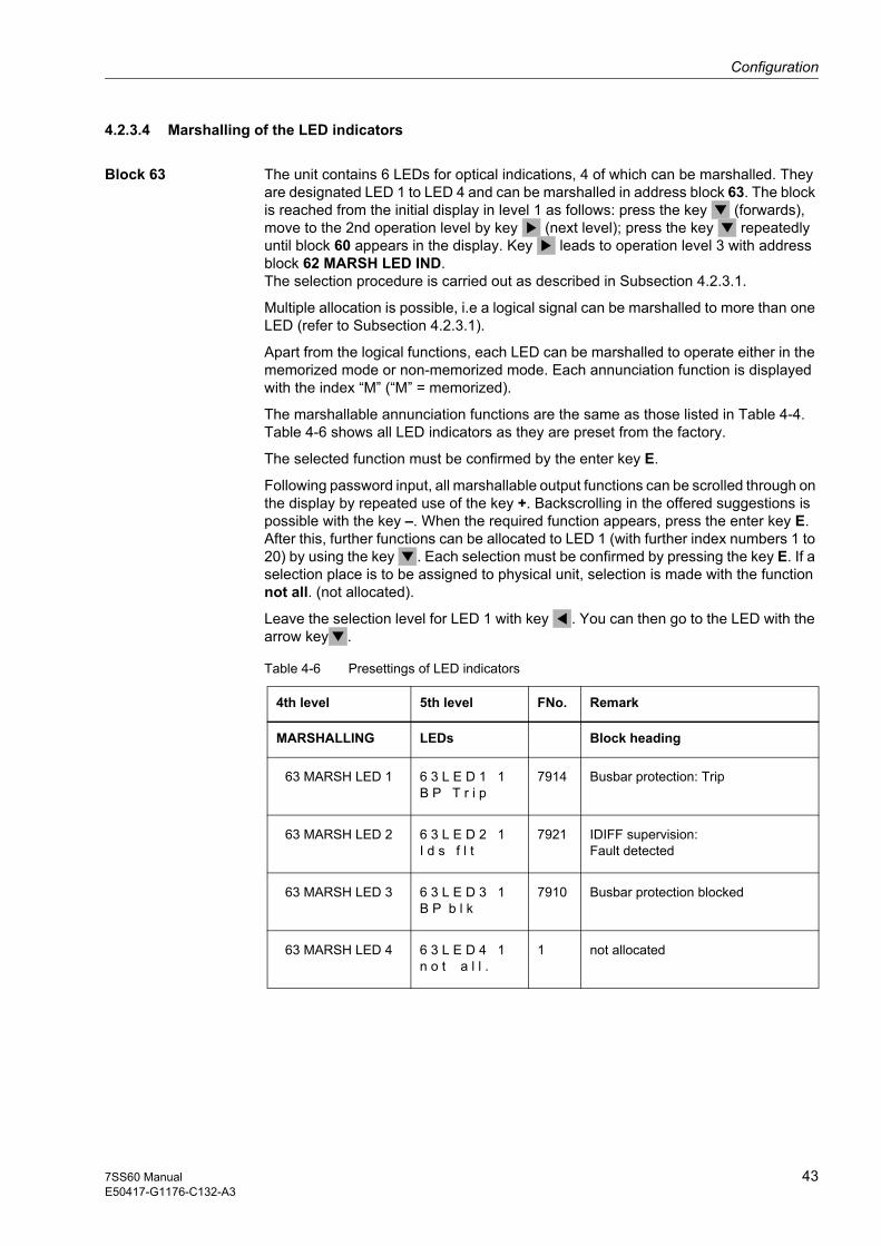
Block 63 The unit contains 6 LEDs for optical indications, 4 of which can be marshalled. They are designated LED 1 to LED 4 and can be marshalled in address block 63. The block is reached from the initial display in level 1 as follows: press the key (forwards), move to the 2nd operation level by key (next level); press the key repeatedly until block 60 appears in the display. Key leads to operation level 3 with address block 62 MARSH LED IND. The selection procedure is carried out as described in Subsection 4.2.3.1.
Multiple allocation is possible, i.e a logical signal can be marshalled to more than one LED (refer to Subsection 4.2.3.1).
Apart from the logical functions, each LED can be marshalled to operate either in the memorized mode or non-memorized mode. Each annunciation function is displayed with the index “M” (“M” = memorized).
The marshallable annunciation functions are the same as those listed in Table 4-4. Table 4-6 shows all LED indicators as they are preset from the factory.
The selected function must be confirmed by the enter key E.
Following password input, all marshallable output functions can be scrolled through on the display by repeated use of the key +. Backscrolling in the offered suggestions is possible with the key –. When the required function appears, press the enter key E. After this, further functions can be allocated to LED 1 (with further index numbers 1 to 20) by using the key . Each selection must be confirmed by pressing the key E. If a selection place is to be assigned to physical unit, selection is made with the function not all. (not allocated).
Leave the selection level for LED 1 with key . You can then go to the LED with the arrow key .
Table 4-6 Presettings of LED indicators
4th level 5th level FNo. Remark
MARSHALLING LEDs Block heading
63 MARSH LED 1 6 3 L E D 1 1B P T r i p
7914 Busbar protection: Trip
63 MARSH LED 2 6 3 L E D 2 1I d s f l t
7921 IDIFF supervision:Fault detected
63 MARSH LED 3 6 3 L E D 3 1B P b l k
7910 Busbar protection blocked
63 MARSH LED 4 6 3 L E D 4 1n o t a l l .
1 not allocated
Configuration
44 7SS60 ManualE50417-G1176-C132-A3
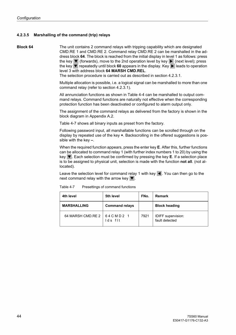
4.2.3.5 Marshalling of the command (trip) relays
Block 64 The unit contains 2 command relays with tripping capability which are designated CMD.RE 1 and CMD.RE 2. Command relay CMD.RE 2 can be marshalled in the ad-dress block 64. The block is reached from the initial display in level 1 as follows: press the key (forwards), move to the 2nd operation level by key (next level); press the key repeatedly until block 60 appears in the display. Key leads to operation level 3 with address block 64 MARSH CMD.REL. The selection procedure is carried out as described in section 4.2.3.1.
Multiple allocation is possible, i.e. a logical signal can be marshalled to more than one command relay (refer to section 4.2.3.1).
All annunciation functions as shown in Table 4-4 can be marshalled to output com-mand relays. Command functions are naturally not effective when the corresponding protection function has been deactivated or configured to alarm output only.
The assignment of the command relays as delivered from the factory is shown in the block diagram in Appendix A.2.
Table 4-7 shows all binary inputs as preset from the factory.
Following password input, all marshallable functions can be scrolled through on the display by repeated use of the key +. Backscrolling in the offered suggestions is pos-sible with the key –.
When the required function appears, press the enter key E. After this, further functions can be allocated to command relay 1 (with further index numbers 1 to 20) by using the key . Each selection must be confirmed by pressing the key E. If a selection place is to be assigned to physical unit, selection is made with the function not all. (not al-located).
Leave the selection level for command relay 1 with key . You can then go to the next command relay with the arrow key .
Table 4-7 Presettings of command functions
4th level 5th level FNo. Remark
MARSHALLING Command relays Block heading
64 MARSH CMD.RE 2 6 4 C M D 2 1I d s f l t
7921 IDIFF supervision: fault detected

Configuration
457SS60 ManualE50417-G1176-C132-A3
4.2.4 Serial interface
4.2.4.1 Function description
Block 72 The 7SS601 measuring system is equipped with a serial RS485 interface. To adapt it to a PC interface, an RS485/RS232 converter is required. Communication via this interface requires some data arrangements such as identification of the device, trans-mission format and transmission rate.
These data are entered to the device in address block 72. password input is necessary (refer to section 4.2.1). The data must be matched to the connected devices.
4.2.4.2 Hints on setting
Device address The identification number of the device within the substation can be set in parameter 72DEVICE (7201). The number can be chosen at liberty, but must be used only once within the plant system. Setting values between 1 and 254 are possible.
If several modules are series-connected, each 7SS601 device must be assigned a different address in the protection and the PC before operation with the DIGSI PC is started.
Feeder address The feeder address is understood to be the unique number of the feeder within the substation. It is set in parameter 72FEEDER (7202). Setting values between 1 and 254 are possible.
Substation address In case more than one substation is addressed, an identification number for each sub-station can be assigned in parameter 72SUBSTA (7203). Setting values between 1 and 254 are possible.
Data format In the parameter 72 PC-SE (7211) the data format of the serial interface can be matched to the application. The recommended data format for the Siemens protection data processing program is DIGSI V3. The other setting option is ASCII, e.g. for ter-minal programs.
Transmission gaps The setting of the GAPS in the parameter 72 GAPS (7214) is relevant only when the device is intended to communicate via a modem. The setting is the maximum time pe-riod which is tolerated by the device when gaps occur during transmission of a tele-gram. Gaps may occur, when modems are used, by compression of data, error cor-rection, and differences of the baud rate. Setting values between 0.0 s and 5.0 s are possible. With good transmission quality between the modems, 1.0 s is recommend-ed. The value should be increased when transmission quality is not so good. It must be noted that GAPS must be smaller than the setting of reaction time protection re-lay in the protection software DIGSI V3. Recommended value:
GAPS Reaction time protection relay2
-------------------------------------------------------------------------------≈
Higher values for reaction time protection relay reduce the transmission speed in case of transmission errors. If the interface is connected directly to a personal com-puter, GAPS may be set to 0.0 s.

Configuration
46 7SS60 ManualE50417-G1176-C132-A3
Baud rate In the parameter 72 BAUD (7215) the baud rate for serial transmission can be changed. The baud rate can be selected by repeatedly pressing the key + or –.
Character format The format for the characters transmitted in a telegram can be set in parameter 72PARITY (7216) to match the following transmission media:
• DIGSI V3 with even parity and 1 stop bit
• Transmission with odd parity and 1 stop bit (8O1)
• Transmission with no parity and 2 stop bits (8N2)
• Transmission with no parity and 1 stop bit (8N1)
4.2.4.3 Overview of parameters
Addr. Parameter Possible settings Default setting Explanation
7201 72DEVICE minimum setting:..... ....1maximum setting:....254
1 ID number of the device within the substation
7202 72FEEDER minimum setting:..... ....1maximum setting:....254
1 Number of feeder within the substation (feeder address)
7203 72SUBSTA minimum setting:..... ....1maximum setting:....254
1 ID number of substation, if more than one substation can be addressed
7211 72 PC-INT DIGSI V3ASCII
DIGSI V3 Data format for the interface
7214 72 GAPS minimum setting: .....0.0 smaximum setting:....5.0 s
1.0 s Maximum permissible transmission gap between telegrams for modem transmission
7215 72PCBAUD 1200 Baud2400 Baud4800 Baud9600 Baud19200 Baud
9600 Baud Transmission baud rate for serial PC- interface
7216 72 PARITY DIGSI V38O18N28N1
DIGSI V3 Parity of transmission telegrams

Configuration
477SS60 ManualE50417-G1176-C132-A3
4.2.5 Setting of date and time
4.2.5.1 Function description
The date and time should not be set until the device is finally installed and connected to the supply voltage, because an outage of the auxiliary voltage resets the clock.
The address block for this setting is reached from the initial display. Press the key three times until the block ADDITION FUNCTION is displayed. Key is pressed to change to the next operation level with the block TIME SETTING. Change to the next operation level with key . The date and time are displayed now. Scroll on with key
to find the setting blocks for date and time.
After the relay has been switched on, first the date 01.01.95 appears and the time since the start-up of the processor system (connection of the supply voltage).
No password is required to change the date and time. Day, month and year can be altered using the keys + and –. Press the key to move between the day, month and year. Each time a value is changed, the enter key E must be pressed before the next number can be changed. Proceed in analog manner to change the time.
Note:
When the day is changed, the display firstly allows 31 days. Only when the month and year is changed can the relay check the plausibility of the complete date (leap year or not). After confirmation with the enter key E, the day may be reduced to an existing number.
4.2.5.2 Hints on setting
Date In the parameter DATE a new date can be entered in the order day, month, year.
Time In the parameter TIME a new time can be entered. First the hour is entered, then the minutes. The seconds are not changed. They are automatically set to zero when the enter key is pressed.

Configuration
48 7SS60 ManualE50417-G1176-C132-A3

497SS60 ManualE50417-G1176-C132-A3
Functions 5This chapter explains the various functions of the SIPROTEC 7SS60 and shows the setting possibilities for each function. It also gives information and - where required - formulae for determination of the setting values.
5.1 Measurement method 50
5.2 Formation of measuring currents from the transformer currents 55
5.3 Power system and switchgear data - Block 01 66
5.4 Busbar protection 68
5.5 Differential current supervision - Block 13 72
5.6 Fault recording - Block 74 74

Functions
50 7SS60 ManualE50417-G1176-C132-A3
5.1 Measurement method
Basic principle The measurement method by which the 7SS60 numerical busbar protection detects a short-circuit in the protected zone relies on Kirchhoff's current law. This law states that the vectorial sum of all currents flowing into a closed area must be zero.
Figure 5-1 Busbar with n feeders
Assuming that the currents J1, J2, J3 to Jn flow in the feeders connected to the busbar, the following equation applies in the fault-free condition (the currents flowing towards the busbar are defined as positive, and the currents flowing away from the busbar as negative):
J1 + J2 + J3 ... + Jn = 0
If this equation is not fulfilled, there must be some other - impermissible - path through which a current flows. This means that there is a fault in the busbar region.
This law is superior, as the basis for busbar protection, to any other known way of measurement. Its simplicity is unequalled: a single quantity, the sum of currents, characterizes, and can be used to detect, faulty conditions. This sum of all currents can be formed at any time, even over a whole cycle, and if formed as such, using instantaneous current values, full use of above law can be made.
The above considerations apply strictly to the primary-side conditions in a high-voltage switching station. Protection systems, however, cannot carry out direct measurements of currents in high-voltage systems. Protection equipment measurement systems, performing the current comparisons, are connected through current transformers. The secondary windings provide the currents scaled down according to the transformation ratio while retaining the same phase relation. Furthermore, the current transformers, due to the isolation of their secondary circuits from the high-voltage system and by appropriate earthing measures, can keep dangerous high voltages away from the protection system.
The characteristics of the current transformers are an important factor for the correct operation of the protection. Their physical locations mark the limits of the protection zone covered by the protection system.
Since the current transformers proportionally transform the primary currents flowing in the system, a single-phase busbar protection that monitors the summated feeder currents would have the basic circuit shown in Figure 5-2.

Functions
517SS60 ManualE50417-G1176-C132-A3
Figure 5-2 Differential protection of a busbar with n feeders, 1-phase, without restraining devices
For simplicity’s sake, it is assumed that the current transformers of all feeders have the same transformation ratio. Although such a busbar protection would certainly detect any short-circuit inside the protection zone, the transformation errors of the current transformers, which are unavoidable to some degree, are also liable to cause spurious tripping as a result of an external short-circuit. In that case, for instance with a close-up fault on one of the feeder bays, the current flowing into the short-circuit is shared on the infeed side by several bays. The current transformers in the infeeding bays carry only a fraction of the total fault current while the current transformer in the faulted feeder bay carries the full current in its primary winding. If the fault current is very high, this set of current transformers may therefore be saturated, so tending to deliver only a fraction of the actual current on the secondary side while the rest of the current transformers, due to the distribution of currents among several bays, perform properly. Although the sum of the currents is zero on the primary side, the sum of the currents in Figure 5-2 is now no longer zero.
In conventional differential protection systems where the sum of the currents is zero on the primary side, for busbars and similar objects, this difficulty is countered by employment of the so-called stabilization (restraining) devices.
If the short-circuit does not occur at the voltage peak of the cycle, a dc component is initially superimposed on the short-circuit current which decays with a time constant τ = L / R of the impedance from source to fault. With the growing output ratings of the generator units, these time constants in the supply system tend to grow longer. A superimposed dc component speeds up the magnetic saturation in the transformer cores, thus considerably affecting the transformation task.
Several measures have been introduced into the 7SS601 measuring system of the 7SS60 busbar protection to cope with these problems. It was thus possible to give the 7SS60 busbar protection system a maximum degree of security against spurious operation for external short-circuits while ensuring, in the event of internal short-circuits, that a tripping signal is initiated within a very short time.
The measuring circuit of the 7SS60 busbar protection system is characterized by the following features:
Basic principle • Monitoring the sum of the currents as the tripping quantity
Measures taken to guard against the disturbing influences due to current-transformer saturation
• Restraint
Measures taken to obtain very short operating times
• Separate evaluation of the current transformer currents during the first milliseconds after the occurrence of a fault (anticipating the current transformer saturation)
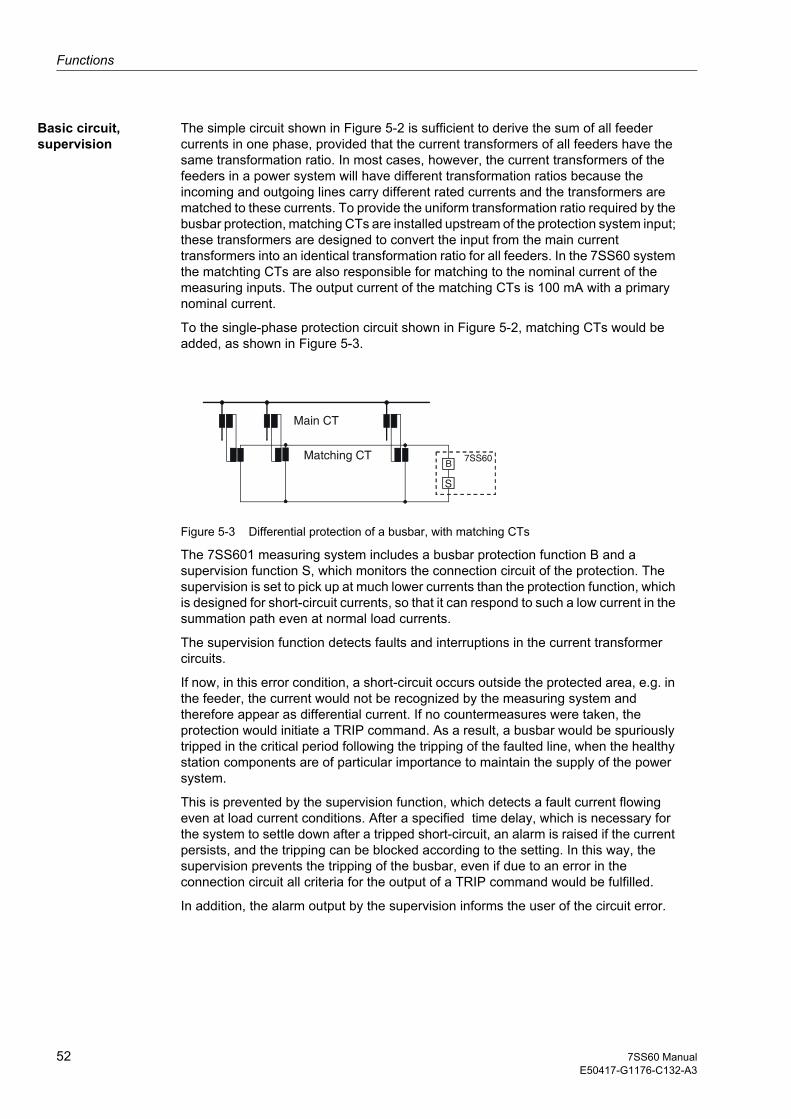
Functions
52 7SS60 ManualE50417-G1176-C132-A3
Basic circuit, supervision
The simple circuit shown in Figure 5-2 is sufficient to derive the sum of all feeder currents in one phase, provided that the current transformers of all feeders have the same transformation ratio. In most cases, however, the current transformers of the feeders in a power system will have different transformation ratios because the incoming and outgoing lines carry different rated currents and the transformers are matched to these currents. To provide the uniform transformation ratio required by the busbar protection, matching CTs are installed upstream of the protection system input; these transformers are designed to convert the input from the main current transformers into an identical transformation ratio for all feeders. In the 7SS60 system the matchting CTs are also responsible for matching to the nominal current of the measuring inputs. The output current of the matching CTs is 100 mA with a primary nominal current.
To the single-phase protection circuit shown in Figure 5-2, matching CTs would be added, as shown in Figure 5-3.
Main CT
Matching CT 7SS60B
S
Figure 5-3 Differential protection of a busbar, with matching CTs
The 7SS601 measuring system includes a busbar protection function B and a supervision function S, which monitors the connection circuit of the protection. The supervision is set to pick up at much lower currents than the protection function, which is designed for short-circuit currents, so that it can respond to such a low current in the summation path even at normal load currents.
The supervision function detects faults and interruptions in the current transformer circuits.
If now, in this error condition, a short-circuit occurs outside the protected area, e.g. in the feeder, the current would not be recognized by the measuring system and therefore appear as differential current. If no countermeasures were taken, the protection would initiate a TRIP command. As a result, a busbar would be spuriously tripped in the critical period following the tripping of the faulted line, when the healthy station components are of particular importance to maintain the supply of the power system.
This is prevented by the supervision function, which detects a fault current flowing even at load current conditions. After a specified time delay, which is necessary for the system to settle down after a tripped short-circuit, an alarm is raised if the current persists, and the tripping can be blocked according to the setting. In this way, the supervision prevents the tripping of the busbar, even if due to an error in the connection circuit all criteria for the output of a TRIP command would be fulfilled.
In addition, the alarm output by the supervision informs the user of the circuit error.

Functions
537SS60 ManualE50417-G1176-C132-A3
Restraint The restraint (stabilization) has the function of reducing the influence on the measurement of transformation inaccuracies (e.g. for transformer saturation) in the various feeders to such a degree that spurious behaviour of the protection system is prevented.
The vectorial sum Id of all feeder currents acts as tripping quantity.
Id = | I1 + I2 + ... + In |
The value sum of the all feeders is counterbalanced by the restraint quantity IR.
IR = | I1 | + | I2 | + ... + | In |
The restraint R is determined by setting the restraint factor.
R = k . IR
MeasuringSystem
"k-factor"
=R
Figure 5-4 Differential current measuring circuit with restraint in the 7SS60 busbar protection system
For an explanation of the circuit shown in Figure 5-4, let us consider first the conditions at a given point in time. The n feeders of the busbars carry the currents J1, J2 ... Jn. These are defined as positive as they flow towards the busbar. The secondary currents I1, I2 ... In from the current transformers, which are proportional to the primary currents if we assume (for the moment) an ideal transmission behaviour, flow individually through the primary windings of the measuring transducers MS and summated through the primary winding of the measuring transducer MD. On the secondary side, each transducer MS of the restraint module feeds a measuring rectifier GS. Regardless of the direction of the individual currents in the measuring transducers, the current direction at the output of the measuring rectifiers is fixed and the same at the considered and any other point in time.
The input Id thus detects the vectorial sum of the currents, and the input IR the summated magnitudes of the currents.
Check zone The safety of operation of the busbar protection system 7SS60 can be further in-creased by an additional so-called check zone.
This requires an additional measuring system which - regardless of the position of the isolator - monitors the current sums of all busbar feeders. Possible tripping failures originating from faulty information sent to the real state of the isolator are thus exclud-ed.
When a busbar fault occurs, a TRIP-command decision is only given if both the meas-uring system belonging to the faulty busbar section and the check zone measuring system gives the decision for tripping (2 out of 2 decision).

Functions
54 7SS60 ManualE50417-G1176-C132-A3
An even higher degree of safety can be achieved by using separate transformer cores for the check zone.
To avoid over-restraint, address 10k fac (1506) in the check zone measuring system has to be a lower level (see Subsection 5.4.2).

Functions
557SS60 ManualE50417-G1176-C132-A3
5.2 Formation of measuring currents from the transformer currents
The measuring quantities used by the busbar protection for the current comparison are the secondary currents supplied by the feeder transformers. They are, however, not fed directly into the measuring circuit but first transformed by means of matching CTs. In the following the reasons are explained:
• For the measuring circuit it is necessary to reproduce the corresponding switch position of the power system. Therefore the rated currents must be changed over. The secondary currents of the transformers (rated current 1 A or 5 A) are not suited for this purpose because the changeover contacts therefore needed to be designed for currents (appearing when a fault occurs) that are much more higher. If the currents are transformed, the changeover contact is less strained. This means that the contact need not be designed for very high currents.
• Usually the current transformers in the outputs do not have the same transformation ratio. However, the measuring circuit requires a consistent transformation of the currents. For the protection differences resulting from the transformation must be balanced by matching CTs.
• The currents of the 3 phases can be summated to a single-phase alternating current by means of a matching CT. In this way, only one measuring system is necessary to protect the 3 phases of the power system. As a consequence, the protection each time picks up differently in its sensitivity, depending on which phase is affected by the fault. In most cases this level of protection is sufficient.
The 7SS60 busbar protection is designed for a rated input current of 100 mA. With the current transformer carrying rated current at the primary side, the current for this feeder that is fed into the protection for comparison will be 100 mA. This applies if 3 phase currents are summated to a single-phase alternating current for a common measuring circuit and if each phase has its own measuring circuit. The latter is preferentially used for protection equipment for busbars in systems of very high rated insulation voltages (380 or 220 kV). However, the consistency of the pickup values for all types of faults costs much more effort. Another reason for using this method preferentially is that the safety is twice or three times higher for tripping in case of two-phase or three-phase faults.
Depending on whether differential protection is applied on all 3 phases together or on each single phase, one has to distinguish between 2 types of input circuits. Each method requires different matching transformers.
There are 2 basic principles:
• phase-selective protection (3 measuring systems in each busbar section)
• protection with summation current transformers (one measuring system in each busbar section)
If summation current transformers are used, a smaller number of modules is sufficient to form a protection system. On the other hand, the asymmetric analog summation of the currents entails different sensitivity of the protection system for different fault types. You can influence the sensitivity by performing the connection mode which is optimally matched to the system conditions. Refer also to the following explanations concerning the normal and increased earth fault sensitivity.
In the version with summation current transformers, increased restraint may be produced by load currents in the phases not involved in the fault current path. But this is of less importance since the fault currents exceed normally clearly the tripping characteristic.

Functions
56 7SS60 ManualE50417-G1176-C132-A3
5.2.1 Summation current transformer methode
The following sections deal with circuit examples for the version with summation current transformers.
The input current transformer (“summation current transformer”) has several primary windings and one secondary winding. The primary windings have different numbers of turns, which allows to connect the three phase currents with a ratio of e.g. 2 : 1 : 3.
Depending on the station operating conditions and the requirements that the protection must meet, there are two different circuits for connecting the summation current transformer to the main transformers.
Differential Current
Restraint Current R
Figure 5-5 Block diagram of the 7SS60 system with summation current transformers

Functions
577SS60 ManualE50417-G1176-C132-A3
5.2.1.1 Normal earth current sensitivity
Figure 5-6 shows the connection circuit for normal earth current sensitivity. It should be considered for power systems with low-resistant or solid earthing of the starpoints where due to the transformer design sufficiently high short-circuit currents can be expected in case of 1-phase earth faults.
One of its characteristics is that the fault detection thresholds for 2-phase short-circuits have a ratio of 1 : 2. With any other winding ratio than 1 : 2 between the windings in the phases, the fault detection thresholds would differ by more than the ratio 1 : 2. This ratio is thus an optimum. In comparison with the fault-free, symmetrical 3-phase current, the ratio is 2 / √3 = 1.15.
For the connection shown in Figure 5-6, we obtain the winding factors W and their ratio to the three-phase symmetrical fault according to table 5-1 for the different fault types. Additionally, the primary currents I1 required for the secondary current IM = 100 mA are indicated. To obtain the actual pickup value, the current setting values have to be multiplied with these factors.
Figure 5-6 Connection circuit of the summation current transformer for normal earth short-circuit sensitivity
Figure 5-7 Vector diagram for 3-phase faults
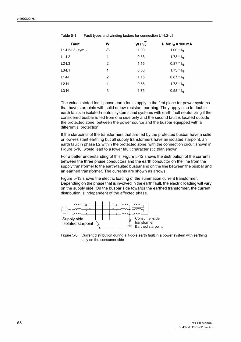
Functions
58 7SS60 ManualE50417-G1176-C132-A3
Table 5-1 Fault types and winding factors for connection L1-L2-L3
Fault W W / √3 I1 for IM = 100 mAL1-L2-L3 (sym.) √3 1.00 1.00 * INL1-L2 1 0.58 1.73 * INL2-L3 2 1.15 0.87 * INL3-L1 1 0.58 1.73 * INL1-N 2 1.15 0.87 * INL2-N 1 0.58 1.73 * INL3-N 3 1.73 0.58 * IN
The values stated for 1-phase earth faults apply in the first place for power systems that have starpoints with solid or low-resistant earthing. They apply also to double earth faults in isolated-neutral systems and systems with earth fault neutralizing if the considered busbar is fed from one side only and the second fault is located outside the protected zone, between the power source and the busbar equipped with a differential protection.
If the starpoints of the transformers that are fed by the protected busbar have a solid or low-resistant earthing but all supply transformers have an isolated starpoint, an earth fault in phase L2 within the protected zone, with the connection circuit shown in Figure 5-10, would lead to a lower fault characteristic than shown.
For a better understanding of this, Figure 5-12 shows the distribution of the currents between the three phase conductors and the earth conductor on the line from the supply transformer to the earth-faulted busbar and on the line between the busbar and an earthed transformer. The currents are shown as arrows.
Figure 5-13 shows the electric loading of the summation current transformer. Depending on the phase that is involved in the earth fault, the electric loading will vary on the supply side. On the busbar side towards the earthed transformer, the current distribution is independent of the affected phase.
Figure 5-8 Current distribution during a 1-pole earth fault in a power system with earthing only on the consumer side

Functions
597SS60 ManualE50417-G1176-C132-A3
Figure 5-9 Summation transformer currents in a 1-pole earth fault in a power system with earthing only on the consumer side; connection as per 5-6
This circuit yields the following conditions in the differential measuring circuit for power systems with earthing only on the consumer side:
Phase Trip valueId
Restraint valueIs Id / Is
L1 0 + 6 0 + 6 6/6 = 1.0
L2 –3 + 6 3 + 6 3/9 = 0.33
L3 3 + 6 3 + 6 9/9 = 1.0
If an earth fault occurs in phase L2 within the protected zone, the fault characteristic has thus only a slope of 0.33 instead of 1.
This circuit is thus not suitable for power systems with earthing only on the consumer side.

Functions
60 7SS60 ManualE50417-G1176-C132-A3
5.2.1.2 Increased earth current sensitivity
Figure 5-10 shows that the windings with the ratio of turns 2 (ratio-2 winding) and 1 (ratio-1 winding) are each connected to one of the three phase currents, and the third winding (ratio-3 winding) is connected to the neutral conductor.
This circuit is used in power systems where system faults involving earth currents are likely to induce relatively small fault currents.
One of its characteristics is that the fault detection thresholds for 2-phase short-circuits have a ratio of 1 : 2. With any other winding ratio than 1 : 2 between the windings in the phases, the fault detection thresholds would differ by more than the ratio 1 : 2. This ratio is thus an optimum. In comparison with the fault-free, symmetrical 3-phase current, the ratio is 2 / √3 = 1.15.
A second characteristic of this connection circuit is its increased sensitivity to earth faults, which is due to the connection of the ratio-3 winding to the earth current path.
For the connection shown in Figure 5-10, we obtain the winding factors W and their ratio to the three-phase symmetrical fault according to table 5-2 for the different fault possibilities. Additionally, the primary currents I1 required for the secondary current IM = 100 mA are indicated. To obtain the actual pickup value, we multiply the current setting values these factors.
Figure 5-10 Connection circuit of the summation current transformer for increased earth current sensitivity
Effectivenumberof windingsin turn
Figure 5-11 Vector diagram for 3-phase faults

Functions
617SS60 ManualE50417-G1176-C132-A3
Table 5-2 Fault types and winding factors for connection L1-L3-N
Fault W W / √3 I1 for IM = 100 mAL1-L2-L3 (sym.) √3 1.00 1.00 * INL1-L2 2 1.15 0.87 * INL2-L3 1 0.58 1.73 * INL3-L1 1 0.58 1.73 * INL1-N 5 2.89 0.35 * INL2-N 3 1.73 0.58 * INL3-N 4 2.31 0.43 * IN
The values stated for 1-phase earth faults apply in the first place for power systems that have starpoints with solid or low-resistant earthing. They apply also to double earth faults in isolated-neutral systems and systems with earth fault neutralizing if the considered busbar is fed from one side only and the second fault is located outside the protected zone, between the power source and the busbar equipped with a differential protection.
If the starpoints of the transformers that are fed by the protected busbar have a solid or low-resistant earthing but all supply transformers have an isolated starpoint, an earth fault in phase L2 within the protected zone, with the connection circuit shown in Figure 5-10, would lead to a lower fault characteristic than shown.
For a better understanding of this, Figure 5-12 shows the distribution of the currents between the three phase conductors and the earth conductor on the line from the supply transformer to the earth-faulted busbar and on the line between the busbar and an earthed transformer. The currents are shown as arrows.
Figure 5-13 shows the electric loading of the summation current transformer. Depending on the phase that is involved in the earth fault, the electric loading will vary on the supply side. On the busbar side towards the earthed transformer, the current distribution is independent of the affected phase.
Figure 5-12 Current distribution during a 1-pole earth fault in a power system with earthing only on the consumer side

Functions
62 7SS60 ManualE50417-G1176-C132-A3
Figure 5-13 Summation transformer currents in a 1-pole earth fault in a power system with earthing only on the consumer side; connection as per Figure 5-10
For the three possible cases, the following conditions apply:
Phase Trip valueId
Restraint valueIs Id / Is
L1 3 + 12 3 + 12 15/15 = 1.0
L2 –3 + 12 3 + 12 9/15 = 0.6
L3 0 + 12 0 + 12 12/12 = 1.0
If an earth fault occurs in phase L2 within the protected zone, the fault characteristic has thus only a slope of 0.6 instead of 1. With such unfavourable conditions, a lower restraint factor should be selected to ensure reliable tripping of the protection in case of internal faults.

Functions
637SS60 ManualE50417-G1176-C132-A3
5.2.2 Phase-selective measurement
The phase-selective measurement method provides equal sensitivity for all fault types. The current is measured separately for each phase. To this end, each secondary current of the primary transformer is fed into a matching transformer. If the transformation ratio of the matching transformers has been selected to match the transformation ratio of the primary current transformer, the matching transformer generates a normalized secondary current. If the primary current is 1 * Irated, the secondary current of the matching transformer is 100 mA.
Figure 5-14 Phase-selective measurement

Functions
64 7SS60 ManualE50417-G1176-C132-A3
5.2.3 Matching transformers
Summation current matching transformers 4AM5120-3/-4
For current summation, matching transformers of the types 4AM5120-3DA00-0AN2 for connection to transformers with a rated secondary current of 1 A (Figure 5-15) and 4AM5120-4DA00-0AN2 for connection to transformers with a rated secondary current of 5 A (Figure 5-16) are used. These summation current matching transformers have one secondary winding with a rated current of 100 mA, but seven input windings for connection to the main current transformers. The numbers of turns in these windings are such that they allow to compensate by appropriate connection circuits any transformation ratio differences in the main transformers. Otherwise, interposing transformers must be used additionally to prevent mismatching. To ensure the required degree of protection, the summation current matching transformers are usually accommodated in cubicles (Figure 9-3). They can also be installed in the proximity of the main current transformers.
Figure 5-15 Windings of the 4AM5120-3DA00-0AN2 summation current matching transformer
Figure 5-16 Windings of the 4AM5120-4DA00-0AN2 summation current matching transformer

Functions
657SS60 ManualE50417-G1176-C132-A3
Matching transformers 4AM5120-1/-2
For the phase-selective differential current busbar protection, matching transformers of the types 4AM5120-1DA00-0AN2 (Figure 5-17) for connection to transformers with a rated secondary current of 1 A and 4AM5120-2DA00-0AN2 (Figure 5-18) for connection to transformers with a rated secondary current of 5 A are used. These matching transformers have one secondary winding with a rated current of 100 mA, but 6 or 4 input windings for connection to the main current transformers. The numbers of turns in these windings are such that they allow to compensate, by appropriate protective circuits, any transformation ratio differences in the main transformers. Otherwise, interposing transformers must be used additionally to prevent mismatching. To ensure the required degree of protection, the matching transformers are usually accommodated in cubicles (Figure 9-3). They can also be installed in the proximity of the main current transformers.
Figure 5-17 Windings of the 4AM5120-1DA00-0AN2 matching transformer
Figure 5-18 Windings of the 4AM5120-2DA00-0AN2 matching transformer
Matching transformers 4AM5272
Matching transformer of type 4AM5272-3AA00-0AN2 are used for each phase if the transformation ratio of the primary current transformer cannot be matched using a 4AM5120 matching transformer. The transformation ratio can be achieved by using an appropriate number of windings.
The auto transformer configuration should be preferred since the losses are smaller and enable more accurate matching.
Figure 5-19 Windings of the 4AM5272-3AA00-0AN2 matching transformer

Functions
66 7SS60 ManualE50417-G1176-C132-A3
5.3 Power system and switchgear data
Note:
If the protection is operated from a personal computer using the DIGSI communication software, the test addresses are identified by a four-digit number. This number will be stated in brackets in the section below.
− Block 01
5.3.1 Function description
The 7SS601 measuring system requires some basic data of the power system and the switchgear so that it can match its functions to these data and to its application. These data are found in block 01 POWER SYST.DAT and in the switchgear data.
Rated frequency The parameter 01 FREQ (1101) is used to set the rated system frequency.
Minimum TRIP command duration
The parameter for the minimum TRIP command duration 01 T-TRP (1134) ensures that all connected circuit breakers are reliably tripped as required.
The minimum TRIP command duration can also prevent damage to the TRIP com-mand contacts of the protection system, which could occur if these contacts were opened before the auxiliary contacts of the circuit breaker(s) have interrupted the flow of current through the trip coil. With the parameter 01 T-TRIP (1134) the minimum du-ration of the TRIP command can be extended long enough to ensure that the flow of current through the trip coil of the circuit breaker is reliably interrupted.
Lockout function The parameter 01 L.Out (1135) causes the TRIP command to be memorized until it is manually reset. A TRIP command that is memorized by the lockout function is not even reset by an auxiliary power outage; it drops off, however, for as long as the auxiliary voltage failure persists, as it has no supply voltage.
>-
Figure 5-20 Logic diagram of the lockout function

Functions
677SS60 ManualE50417-G1176-C132-A3
5.3.2 Hints on setting
Rated system frequency
The default setting is 50 Hz; it needs to be changed only for a system frequency of 60 Hz. 16.7 Hz are available in a version with separate order no.
Note:
The parameter 01 FREQ (1101) can only be called up in versions for 50 Hz or 60 Hz. In systems with a rated frequency of 16.7 Hz, the parameter 01 FREQ (1101) is not displayed at all.
Lockout function If the Lockout function is set to ON, the lockout state can only be reset via a binary input. If ON/butt. is set, the lockout can be reset with the N key or with a binary input.
5.3.3 Overview of parameters
DIGSIaddr.
Parameter Possible settings Default setting Explanation
1101 01 FREQ 50 Hz60 Hz
50 Hz Rated frequency of power system
1134 01 T-TRP 0.01 s to 32.00 s 0.15 s Minimum duration of TRIP command
1135 01 L.Out OFFONON/key
OFF Lockout function
5.3.4 Annunciations
FNo. Text on LC display Logical functions
7721 LockOut Lockout state

Functions
68 7SS60 ManualE50417-G1176-C132-A3
5.4 Busbar protection
5.4.1 Function description
The busbar protection function generates the TRIP command that is then multiplied by means of peripheral modules to enable the output to all tripping circuit breakers. It makes the r.m.s. values of the differential current Id and of the restraint current IR available for display, stores events in the form of operational annunciations, fault annunciations or spontaneous annunciations and outputs these via LED indicators or signal relays. Measured values and annunciations are furthermore made available at the RS485 interface for operation by PC using the DIGSI communication software.
The 7SS601 measuring system processes the externally formed sums of the differential current Id and of the restraint current IR. By means of these two measured values, the protection function recognizes the presence of a fault in its associated protection zone. Figure 5-21 shows the trip characteristic of the protection. The characteristic is divided into a horizontal portion and a portion with a steadily rising slope. Only value pairs of a differential and a restraint current that are both above the characteristic constitute busbar faults that lead to a TRIP command. The level of the horizontal portion of the characteristic is determined by the parameter 10Id> (1505). The slope of the rising portion can be varied by the setting of the parameter 10 K fac (1506). The parameter 13ID thr (1802) constitutes the selectable threshold for the differential current supervision.
The algorithm of the 7SS601 measuring system is optimized for the fastest possible tripping in case of a busbar short-circuit. The stability of the protection against external faults is ensured if the transformer saturation occurs not before 3 ms.
Id>
0
Differential current Id
Restraint current IR
ID thr
k = 0.80
k = 0,25
Pick-upcharact-eristics
Tripping zone
Restraintzone
Normal load line
.
.
.
.
.
.
.
.
Figure 5-21 Characteristic of the 7SS601 measuring system
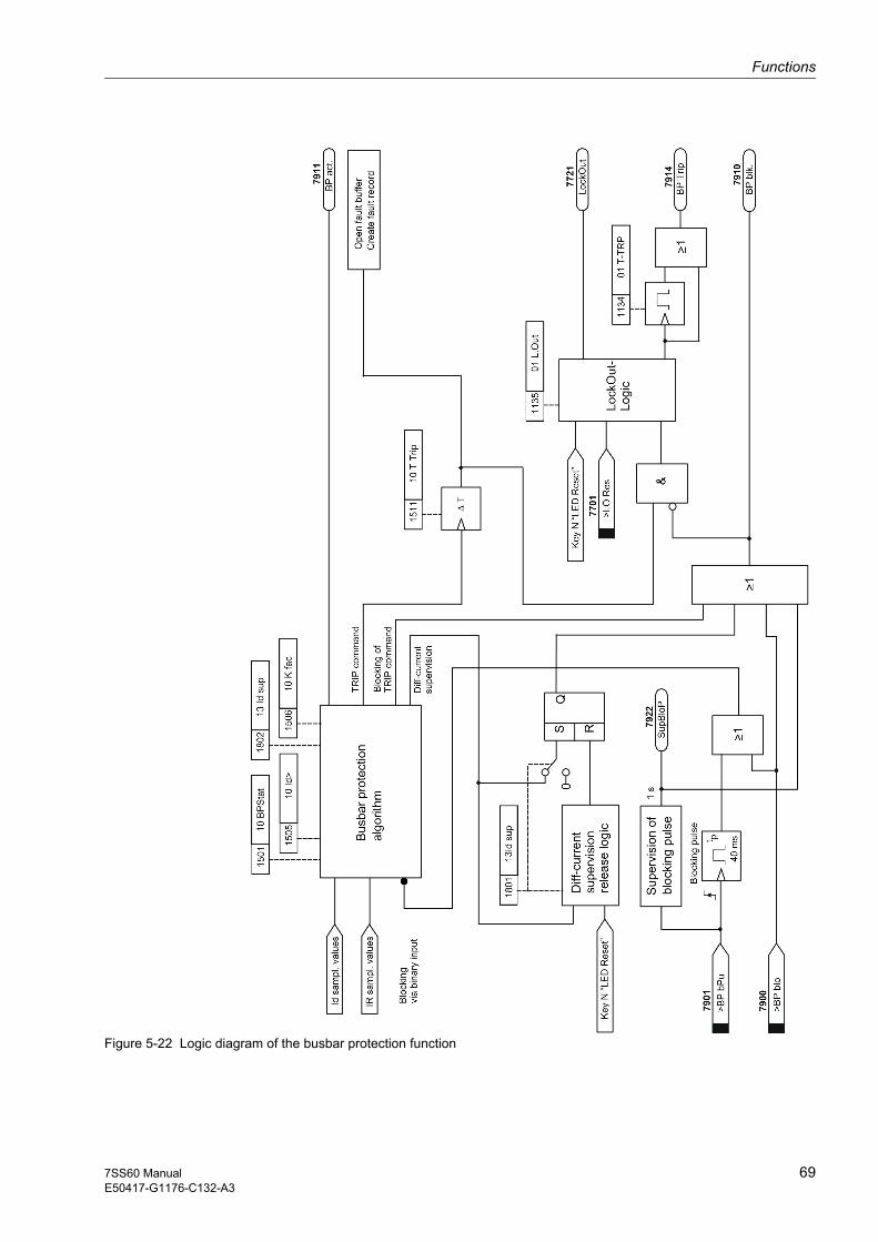
Functions
697SS60 ManualE50417-G1176-C132-A3
Figure 5-22 Logic diagram of the busbar protection function

Functions
70 7SS60 ManualE50417-G1176-C132-A3
5.4.2 Hints on setting
Busbar protection The parameter 10BPstat (1501) is used to activate (ON) or deactivate (OFF) the busbar protection function. It can also be set to block the command and signal relays while the protection function is active (BLO.TRP).
Pick-up value for differential current
For fault detection and tripping the protection only uses the normalized currents Id and IR which exceed the threshold set in 10Id> (1505). The fault detection is reset when the value drops below the threshold again.
The threshold 10Id> (1505) has an influence on the sensitivity of the protection for small fault currents. If weak infeed conditions or the type of neutral point grounding only generate ground fault currents in the load range, 10Id> (1505) may have to be set below the rated value. It must be borne in mind, though, that with a high load the failure of one current transformer might then cause a trip of the busbar. In this case additional criteria must ensure the stability (e.g. additional release via the displace-ment voltage by means of a feeder protection device).
Delay of the TRIP command
A time delay is implemented between the protection algorithm initiating the tripping and the output of the actual TRIP command. This time step causes the delayed initialization of the TRIP command (if a tripping time other than zero is specified). The TRIP command is only executed if during the entire time step the tripping is issued by the protection algorithm. The time step will be reset prematurely if the protection algorithm assumes the tripping conditions to be no longer fulfilled. The delay time of the TRIP command can be specified as the parameter 10 TrpDly (1511). Due to the system configuration the timer accuracy is ± 10 ms.
Restraint factor The restraint factor 10 K fac (1506) allows to adapt the stability of the protection to service conditions.
Although a high setting for this factor improves the stability with regard to faults outside the protected zone, it reduces the sensitivity for the detection of busbar faults.
10 K fac (1506) should therefore be chosen as low as possible and as high as necessary.
If the measuring system is to be used for zone-selective protection, which will be the case in most applications, it is advisable to use the default setting of 10 K fac (1506).
Where a measuring system is used for protection of the so-called check zone, a lower value for 10 K fac (1506) is recommended to avoid that the load currents of the non-faulted busbar sections cause an over-restraint.
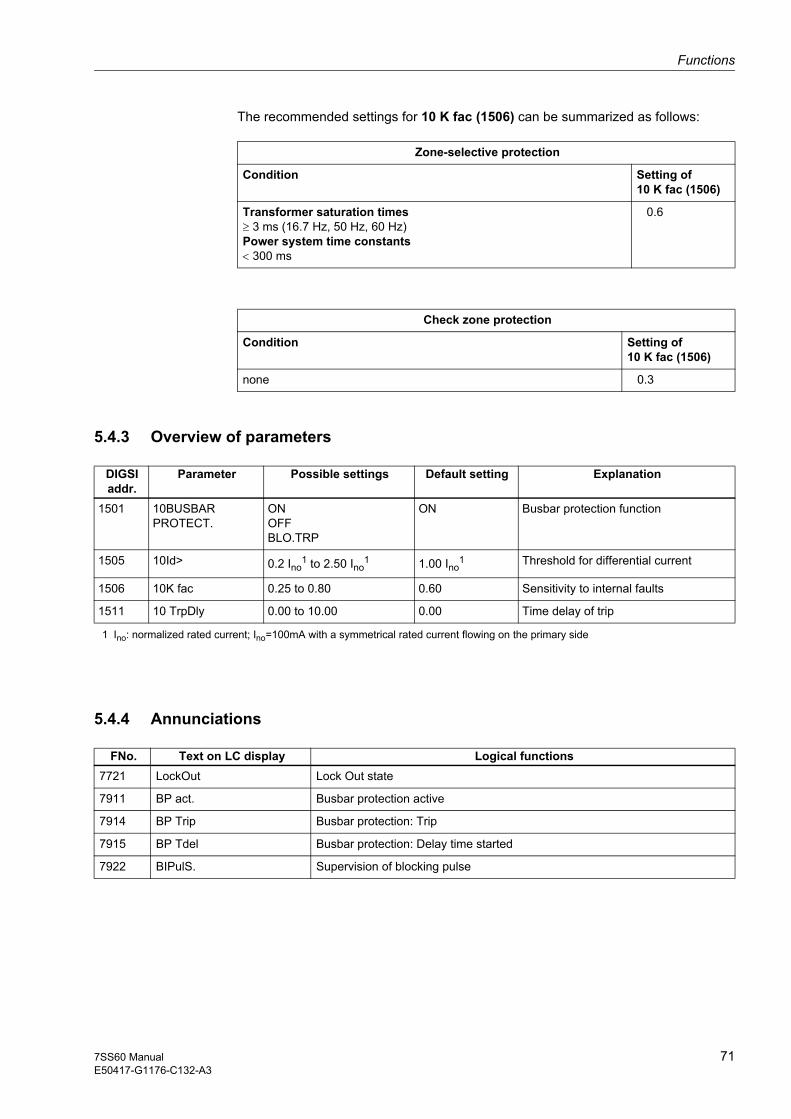
Functions
717SS60 ManualE50417-G1176-C132-A3
The recommended settings for 10 K fac (1506) can be summarized as follows:
Zone-selective protection
Condition Setting of10 K fac (1506)
Transformer saturation times≥ 3 ms (16.7 Hz, 50 Hz, 60 Hz) Power system time constants < 300 ms
0.6
Check zone protection
Condition Setting of10 K fac (1506)
none 0.3
5.4.3 Overview of parameters
DIGSIaddr.
Parameter Possible settings Default setting Explanation
1501 10BUSBAR PROTECT.
ONOFFBLO.TRP
ON Busbar protection function
1505 10Id> 0.2 I
1 Ino: normalized rated current; Ino=100mA with a symmetrical rated current flowing on the primary side
no1 to 2.50 Ino
1 1.00 Ino1 Threshold for differential current
1506 10K fac 0.25 to 0.80 0.60 Sensitivity to internal faults
1511 10 TrpDly 0.00 to 10.00 0.00 Time delay of trip
5.4.4 Annunciations
FNo. Text on LC display Logical functions7721 LockOut Lock Out state
7911 BP act. Busbar protection active
7914 BP Trip Busbar protection: Trip
7915 BP Tdel Busbar protection: Delay time started
7922 BIPulS. Supervision of blocking pulse

Functions
72 7SS60 ManualE50417-G1176-C132-A3
5.5 Differential current supervision − Block 13
5.5.1 Function description
The 7SS60 also allows to supervise the external transformer circuits. The supervision picks up when the threshold 13Id thr (1802) is exceeded. This response comes with a delay after the protection function.
The differential current supervision function is available in block 13. It has the task of detecting malfunctions during operation and blocking so that they do not jeopardize the stability of the system against external faults. This supervision function recognizes transformer failures, e.g. due to phase failures, and sends an alarm. The differential current supervision is able to block the protection if set before.
Figure 5-23 Release logic of the differential current supervision
5.5.2 Hints on setting
Differential current supervision
The parameter 13Id sup (1801) is used to activate and deactivate the differential cur-rent supervision function. The following setting options are offered for the differential current supervision: blocking of the busbar protection till the automatic release by Differential current supervision (bl/relBP), blocking till the acknowledgement by pressing the Key N "LED Reset" (bl/ackBP), or only output an alarm (ALRMonly). With OFF the function can be deactivated.
Pick-up threshold In each measuring cycle, i.e. every 0.5 ms, it is checked whether the peak of the dif-ferential current exceeds the threshold 13Id thr (1802) taking into consideration a hys-teresis. In this case, the counter is increased by 1. Once the counter has reached a value of 5000, the differential current supervision picks up. If no threshold was exceed-ed, the counter is reset to zero.

Functions
737SS60 ManualE50417-G1176-C132-A3
5.5.3 Overview of parameters
DIGSIaddr.
Parameter Possible settings Default setting Explanation
1801 13Id Sup bl/relBPbl/ackBPALRMonlyOFF
bl/relBP Differential current supervision function
1802 13Id thr 0.10 I
1 Ino: normalized rated current; Ino=100 mA with a symmetrical rated current flowing on the primary side
no1 to 1.00 Ino
1 0.15 Ino1 Threshold of differential current
supervision
5.5.4 Annunciations
FNo. Text on LC display Logical functions
7921 IdS Flt IDIFF supervision: fault detected

Functions
74 7SS60 ManualE50417-G1176-C132-A3
5.6 Fault recording − Block 74
5.6.1 Function description
The 7SS601 protection system has a fault recording function that stores the instantaneous values of the differential and the restraint current in a buffer. This function is available in block 74.
The instantaneous values of the measured quantities are sampled every 0.5 ms (50, 60 and 16.7 Hz).
In the event of a fault, the data are stored during a settable period. The available buffer has a recording capacity of 7.1 s.
Up to 8 fault events can be stored in this buffer. New fault events are always entered in the fault record buffer. Older records are overwritten by the new data.
The data can be read out to a personal computer via the serial interface, and processed using the DIGSI / SIGRA software. The measured values are prepared for a graphical display. In addition, signals are represented as binary traces, e.g. Busbar protection: Trip and Lock Out state.
Part of the fault recording memory in the 7SS601 is buffered against voltage failures. The buffered portion has a capacity of 2,5 s. It contains always the most recent fault events.
A fault event starts with tripping by a protection function and ends with the reset of the last tripping by a protection function. Fault records in the 7SS601 always cover this span of time (plus the pre-fault and the post-fault time).
5.6.2 Hints on setting
Times The actual storage time starts with the pre-fault time 74 T-PRE (7411) that precedes the reference point and ends when the post-fault time 74 T-POS (7412) following the disappearance of the storage criterion has elapsed. The maximum permissible total storage time per fault record is set in 74 T-MAX (7410). A total of 7.1 s is available for fault recording.
5.6.3 Overview of parameters
DIGSIaddr.
Parameter Possible settings Default setting Explanation
7410 74-T MAX 0.20 s to 5.00 s 1.50 s Maximum time period of a fault recording
7411 74 T-PRE 0.05 s to 1.50 s 0.30 s Pre-trigger time for fault recording
7412 74 T-POS 0.05 s to 1.50 s 0.20 s Post-fault time for fault recording

757SS60 ManualE50417-G1176-C132-A3
Control in Operation 6This chapter deals with the control of the SIPROTEC 7SS60 system while it is in op-eration. It describes how to obtain information from the system, to set the date and time and to check the status of the binary inputs.
Detailed knowledge of the functioning of the system is not required. A prerequisite for control is, however, that the system settings have been made as described in Chapter 4, and especially that the input and output functions have been marshalled.
6.1 Read-out of information 76
6.2 Read out of the date and time 79
6.3 Testing the status of the binary inputs/outputs 79

Control in Operation
76 7SS60 ManualE50417-G1176-C132-A3
6.1 Read-out of information
General The device provides the following information for local readout or for transmission to DIGSI:
• Operational annunciations
• Fault annunciations
• Measured values
The following section describes in detail how this information is called up, and explains the individual items of information.
6.1.1 Output of annunciations and measured values
Annunciations inform the user during operation of measured data, station data and of the status of the device itself. After a fault in the power system, they also provide an overview of important data concerning the fault and the device function, and are used to verify functional procedures during testing and commissioning.
No password is required for reading out events.
Annunciations generated in the device can reach the user in different ways:
• Indication by LEDs on the device front panel
• Activation of binary outputs (output relays) through the device terminals
• Display on a PC monitor through the serial link, using the DIGSI communication software
• Display on the LC display on the front panel
LEDs The green LED labelled Service/Betrieb is continuously on during normal operation.
The red LED labelled Blocked/Störung shows that the processor system has detect-ed an internal malfunction. If this LED lights during operation, the device is not opera-tional. Chapter 8 tells you what to do in such a case.
The other LEDs on the front panel indicate the annunciations that have been mar-shalled to them, refer to Chapter 4.
Those LEDs indicating states will be lit for as long as the status applies.
If the LED indications are memorized (e.g. fault detection by protection system), the memory can be reset with the N key. This key is also used for a functional check of the LEDs. When it is pressed, all these LEDs must light up.
LEDs indicating a state are on for as long as the state lasts.
Output relays Annunciations that have been marshalled to output relays (refer to chapter 4) are transmitted by means of a signal voltage. They are then available for a station control or telecontrol system.

Control in Operation
777SS60 ManualE50417-G1176-C132-A3
Read-out using the DIGSI communication software
The procedure for reading out the operational and fault annunciation buffer and the measured values using the DIGSI communication software is described in the manual for the communication software.
Readout using the integrated keypad
From the initial state, the block ANNUNC (5000) is reached by pressing the key twice.
The password is not required.
The annunciations are grouped as follows:
• Operational annunciations 81 OPER. ANNUNC (8100) These are annunciations that may be generated during operation of the device: in-formation on device states etc.
• Fault annunciations 82 FAULT ANNUNC. (8200) Here the annunciations of the last eight power system faults can be read out; fault detection, trip commands, chronological sequences etc. According to the definition, a power system fault begins with the first fault detection by a protection function and ends with the reset of the last fault detection.
• Measured values 84 MEAS. VALUES (8400) Display of measured values: differential and restraint current
Note:
A complete list of all annunciation and output functions and their associated function numbers (FNo.) can be found in Appendix A.8.
Pressing the key brings you to the next operation level, where you can call up suc-cessively all annunciation blocks using the and keys.
Operational annunciations Block 81
Operational annunciations are information that the device generates during operation and that concerns the operation. They are available in block 81. Important events and status changes are listed there in chronological order with the time of their occurrence. Up to 30 operational events are stored. If more events are issued, the oldest are over-written.
You can move from block 81 OPER. ANNUNC (8100) to the operational events buffer by pressing the key.
The events are stored in lists. After selecting the desired block, you can scroll the vis-ible part of the list on the display up and down using the and keys, as shown in the following example.

Annunciation buffer
:14.10.9509:45:34380 ms Display
FAULT20 msFT det150 msDIF Trp:
Control in Operation
78 7SS60 ManualE50417-G1176-C132-A3
Faults in the primary switchgear are indicated only with “Fault” and a consecutive fault number. Detailed information on the sequence of events during a fault is contained in the block Fault annunciations.
Fault annunciations Block 82
Here the annunciations of the last eight faults can be read out. These are sorted from the newest to the oldest in a subordinate level of block 82. When a ninth fault arrives, the system deletes the data of the oldest one. Each of the eight fault buffer can store up to 30 annunciations. If more events are issued, the oldest are overwritten.
As long as the date and time of the device have not been set, the date and time dis-played are the relative date and time since the last startup of the processor system. Next, the fault events are displayed in the chronological order of their detection, with a relative time referred to the moment at which the fault started.
Pressing the key brings you from block 82 FAULT ANNUNC. (8200) to the fault annunciations, where you can call up successively all fault annunciations using the and keys.
To move from the selected fault annunciation to the fault annunciation buffer, press the key.
Just like the operational annunciations, the fault annunciations are stored in lists. Use the and keys to scroll though the lists.
Measured values Block 84
Measured values for the differential and restraint current can be displayed in block 84. Values are shown in percent of the nominal values. A prerequisite for correct display is that the nominal data have been correctly set in block 00.
Pressing the key brings you from block 84 MEAS. VALUES (8400) to the mea-sured values, which can now be called up successively using the and keys.
The values are updated during the read-out. When scrolling within the block with the or key, the updated values are displayed.
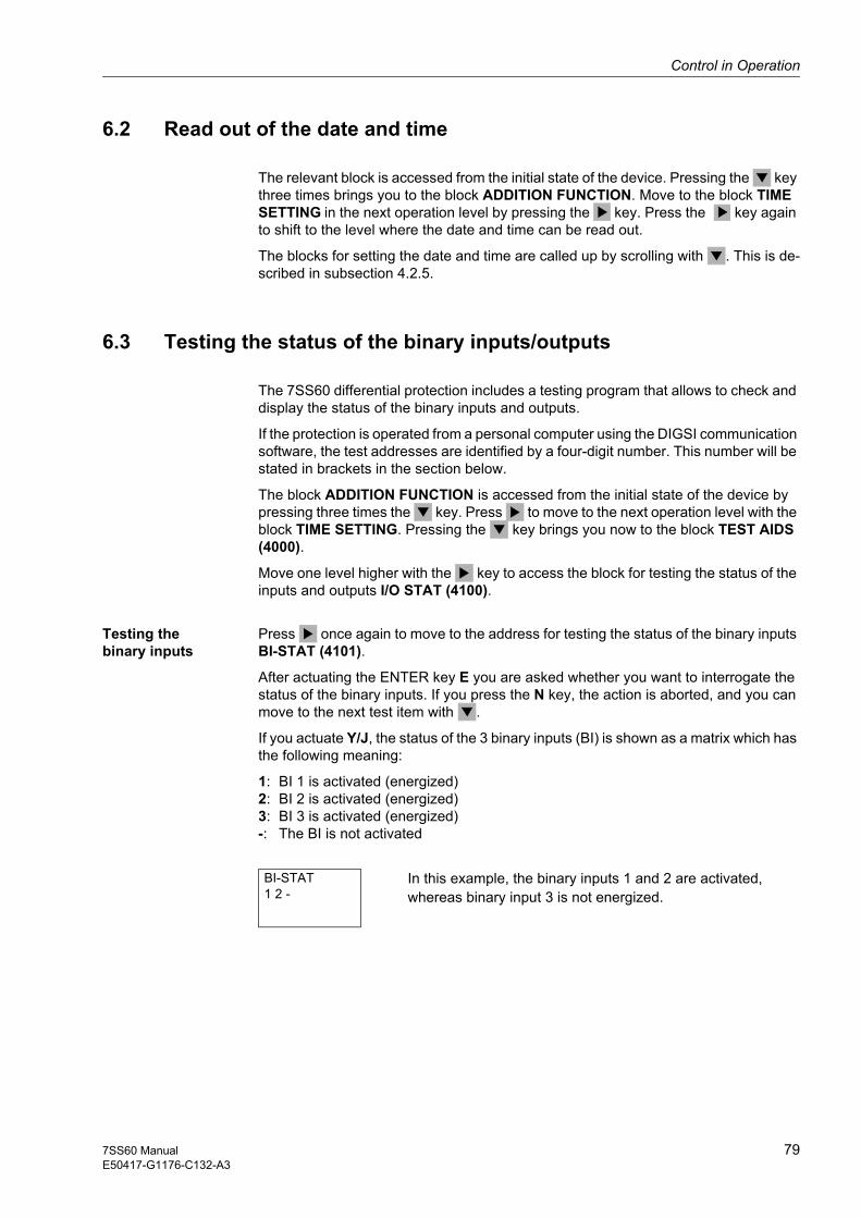
Control in Operation
797SS60 ManualE50417-G1176-C132-A3
6.2 Read out of the date and time
The relevant block is accessed from the initial state of the device. Pressing the key three times brings you to the block ADDITION FUNCTION. Move to the block TIME SETTING in the next operation level by pressing the key. Press the key again to shift to the level where the date and time can be read out.
The blocks for setting the date and time are called up by scrolling with . This is de-scribed in subsection 4.2.5.
6.3 Testing the status of the binary inputs/outputs
The 7SS60 differential protection includes a testing program that allows to check and display the status of the binary inputs and outputs.
If the protection is operated from a personal computer using the DIGSI communication software, the test addresses are identified by a four-digit number. This number will be stated in brackets in the section below.
The block ADDITION FUNCTION is accessed from the initial state of the device by pressing three times the key. Press to move to the next operation level with the block TIME SETTING. Pressing the key brings you now to the block TEST AIDS (4000).
Move one level higher with the key to access the block for testing the status of the inputs and outputs I/O STAT (4100).
Testing the binary inputs
Press once again to move to the address for testing the status of the binary inputs BI-STAT (4101).
After actuating the ENTER key E you are asked whether you want to interrogate the status of the binary inputs. If you press the N key, the action is aborted, and you can move to the next test item with .
If you actuate Y/J, the status of the 3 binary inputs (BI) is shown as a matrix which has the following meaning:
1: BI 1 is activated (energized) 2: BI 2 is activated (energized) 3: BI 3 is activated (energized) -: The BI is not activated
BI-STAT1 2 -
In this example, the binary inputs 1 and 2 are activated, whereas binary input 3 is not energized.

Control in Operation
80 7SS60 ManualE50417-G1176-C132-A3
Testing the signal and command relays
Press to move to the address for testing the status of the signal and command relays RE-STAT (4102).
After actuating the ENTER key E you are asked whether you want to interrogate the status of the signal and command relays. If you press the N key, the action is aborted, and you can move to the next test item with .
If you actuate Y/J, the status of the 2 signal relays (S) and of the 2 command relays (T) is shown as a matrix which has the following meaning:
1: S 1 or T 1 has picked up 2: S 2 or T 2 has picked up -: The relay has not picked up
RE-STATS1-- T-2
In this example, the signal relay S 1 and the command relay T 2 have picked up.
Testing the LEDs Press to move to the address for testing the status of the LEDs LED STATUS (4103).
After actuating the ENTER key E you are asked whether you want to interrogate the status of the LEDs. If you press the N key, the action is aborted, and you can move to the next test item with .
If you actuate Y/J, the status of the 4 LEDs is shown as a matrix which has the follow-ing meaning:
1: LED 1 is activated 2: LED 2 is activated 3: LED 3 is activated 4: LED 4 is activated -: The LED is not activated
LED STATUS- 2 - 4
In this example, LED 2 and LED 4 are activated.

817SS60 ManualE50417-G1176-C132-A3
Installation and Commissioning 7This section is primarily for personnel who are experienced in installing, testing, and commissioning protective and control systems, and are familiar with applicable safety rules, safety regulations, and the operation of the power system. Some modifications of the hardware to the station data may be necessary. For primary tests, the switch-gear must be isolated to perform switching operations.
7.1 Installation and connection 82
7.2 Commissioning 85
Installation and Commissioning
82 7SS60 ManualE50417-G1176-C132-A3
7.1 Installation and connection
Warning! Trouble free and safe use of this SIPROTEC device depends on proper transport, storage, installation, and application of the device according to the warnings in this in-struction manual.
Of particular importance are the general installation and safety regulations for work in a high-voltage environment (for example, ANSI, IEC, EN, DIN, or other national and international regulations.) These regulations must be observed. Failure to observe these precautions can result in death, personal injury, or severe damage of property.
Prerequisites The rated data of the device have been checked as described in section 3.2.1, and their conformity with the station data has been verified. Please note also the prerequi-sites stated in section 9.4.
7.1.1 Measuring system
Panel flush mounting or cubicle mounting
Slip away the covering caps at the top and bottom of the front panel, making acces-sible 4 elongated holes.
Insert the unit into the panel cutout or cubicle mounting frame and fix with four screws (a dimension drawing is shown in Figure 9-1.
A solid low-resistant and low-inductive operating earth has to be connected to the housing’s rear wall using at least one of the two M4 screws. Earth tapes according to DIN 72333 Form A are suitable for this.
Make electrical connections via the screw terminals of the housing. Special atten-tion has to paid to the designations of the connection modules, the permissible con-ductor cross-sections and tightening torque (refer also to chapter 2). Use copper conductors only!
The shielding of the serial RS485 interface must be earthed.
Auxiliary voltage Three different ranges of auxiliary voltage can be delivered (refer to chapter 9 and A.4). If, for exceptional reasons, the rated voltage of the supply input is to be changed to adapt it to the station conditions, it must be taken into account that the models for rated auxiliary voltage DC 60/110/125 V and DC 220/250 V differ from each other by different plug jumpers. The assignment of the jumpers to the rated voltage levels, and their location on the p.c.b., is shown in Figure A-5. The model for DC 220/250 V is suitable for AC 115 V, too. When the device is deliv-ered, all the jumpers are correctly located and matched to the specification given on the rating plate, so that normally none of them need to be altered.
Control voltage for binary inputs
When the device is delivered from the factory, the binary inputs are set to operate with a dc control voltage in the whole operating range between 17 V and 288 V. If the sta-tion control voltage has a higher rating (≥ DC 110 V), it may be useful to set a higher pick-up threshold of the binary inputs to increase the static signal-to-noise ratio. This helps to avoid spurious pick-up by interference voltages that may be caused e.g. by earth fault monitoring systems operating in parallel to the device.

Installation and Commissioning
837SS60 ManualE50417-G1176-C132-A3
To increase the pick-up threshold of a binary input to approx. 74 V, one jumper posi-tion per input must be changed. Figure A-5 shows the assignment of the jumpers to the binary inputs, and their location on the p.c.b.
Slip away the covering caps at the top and bottom of the front panel, making acces-sible one screw each in the top and bottom center. Unscrew these two screws.
Warning! Electrostatic discharges via the component connections, the p.c.b. tracks or the con-necting pin must be avoided under all circumstances by previously touching an earthed metal surface.
Pull out the module by taking it at the front cover and place it on a surface which is suited to electrostatically endangered components (EEC).
Set the jumpers according to Figure A-5.
Insert the module into the housing.
Fix the module into the housing by tightening the two fixing screws.
Re-insert the covers.
7.1.2 Peripheral modules
Panel flush mounting or cubicle mounting
Slip away the covering caps at the top and bottom of the housing front, making ac-cessible 4 elongated holes.
Insert the unit into the panel cutout or cubicle mounting frame and fix with four screws (a dimension drawing is shown in Figure 9-2).
Unscrew the screws next to the fixing screws to remove the front cover.
A solid low-resistant and low-inductive operating earth has to be connected to the housing’s rear wall using at least one of the two M4 screws. Earth tapes according to DIN 72333 Form A are suitable for this.
The peripheral modules are selected in accordance with the station configuration, re-fer to section 4.1. It may be necessary to adapt the auxiliary voltage of the modules or the required contact (NC/NO contact) to the particular station conditions.
Warning! Electrostatic discharges via the component connections, the p.c.b. tracks or the con-necting pin must be avoided under all circumstances by previously touching an earthed metal surface.

Installation and Commissioning
84 7SS60 ManualE50417-G1176-C132-A3
Auxiliary voltage Both the 7TM70 restraint/command output module and the 7TS720 command output module have three input voltage ranges for the auxiliary voltage: DC 48/60 V, DC 110/125 V and DC 220/250 V (refer to Chapter 9 and Appendix A.5). The voltage range can be selected by changing the jumper settings on the module. The assignment of the jumpers to the rated voltage levels, and their location on the p.c.b., is shown in fig-ures A-6 and A-8. Before mounting the peripheral module, check whether the selected auxiliary voltage matches the substation conditions.
Relay contacts (NC/NO contacts)
On the 7TR71 preferential treatment/isolator replica module some of the relay con-tacts can be set either as NC or NO contacts. The relay contacts must be matched to the configurations. The assignment of the jumpers to the respective functions is shown in the block diagram A.3. The physical location of the jumpers on the p.c.b. is shown in Figure A-7.
Insert the peripheral modules into their slots and secure them with a screw from the back of the housing. The slots are numbered and color-coded, refer to Figure 2-3.
The peripheral modules are identified by a labelling strip on which the current con-figuration is stated. The configuration information should contain the designation of the peripheral modules in accordance with their mounting position, and their voltage ranges. Each peripheral module housing has a rating sticker that should be placed on the top of the housing after installing the peripheral modules.
Make electrical connections via the screw-type connection modules. Special atten-tion has to paid to the designations of the connection modules, the permissible con-ductor cross-sections and tightening torques (refer also to chapter 2). Use copper conductors only!
Note:
As the plug-on connectors and pins of the different peripheral modules are not coded, the plug-on connectors must be marked to make their allocation to the appropriate pin connectors on the peripheral modules possible. The marking system for this is shown in Figure 2-2. The marking should contain the following information:
• Number of the peripheral module housing
• Slot identification (A, B, C, D) of the module
• Top connector (X1) or bottom connector (X2)
• Terminals on the connector (1-10, 11-20, 21-30, 31-40)
Replace the front cover on the housing.
Re-insert the covers.

Installation and Commissioning
857SS60 ManualE50417-G1176-C132-A3
7.2 Commissioning
Warning! Hazardous voltages are present in this electrical equipment during operation. Non–observance of the safety rules can result in severe personal injury or property dam-age.
Only qualified personnel shall work on and around this equipment after becoming thor-oughly familiar with all warnings and safety notices of this manual as well as with the applicable safety regulations.
Particular attention must be drawn to the following:
• The earthing screw of the device must be connected solidly to the protective earth conductor before any other electrical connection is made.
• Hazardous voltages can be present on all circuits and components connected to the supply voltage or to the measuring and test quantities.
• Hazardous voltages can be present in the device even after disconnection of the supply voltage (storage capacitors!).
• After switching of the auxiliary voltage, 10 s should be allowed to elapse before switching the auxiliary voltage on again, in order to ensure defined start-up condi-tions.
The limit values stated in chapter 9.1 must not be exceeded at all, not even during test-ing and commissioning.
When performing tests with secondary test equipment, attention must be paid that no other measuring values are applied and that the trip command lines to the circuit breakers are interrupted, unless explicitly stated otherwise.
DANGER! The CT secondary terminals must be short-circuited on the CTs before the cur-rent supply conductors to the device are interrupted!
Where a testing switch is provided which short-circuits the CT secondary lines auto-matically, it is sufficient to set it to “Test” position, provided that the short-circuiters have been checked previously.
The commissioning procedure requires to perform switching operations. The tests de-scribed assume that they can be performed safely. Therefore, they are not suited for checks during operation.
Warning! Primary test may only be carried out by qualified personnel, who are familiar with the commissioning of protection systems, the operation of the plant and the safety rules and regulations (switching, earthing, etc.).
Installation and Commissioning
86 7SS60 ManualE50417-G1176-C132-A3
7.2.1 Checking the connection circuit
The busbar protection is delivered in individual components. The configuration, wiring and testing of the system has to be made specifically to match the station conditions.
Note:
The wiring of the relays on the individual peripheral modules depends on the polarity. Therefore, the wiring must be checked against the block circuit diagrams in Appendix A.3.
In particular, it is recommended to check by a continuity test the status of the connect-ing leads to the current transformers, to the input or summation current and matching transformers (where required, if the modules are installed outside the cubicle or cubi-cles), and to the station battery, the circuit breakers, the isolator auxiliary contacts and any connected signalling equipment. The applicable plans for the power system must be observed.
7.2.1.1 Infeed circuits of the protection
Before switching on the station battery, the correctness of the rated voltages and of the polarity must be checked.
Trip circuits Check the trip circuits for controlling the circuit breakers. Where service conditions do not allow to trip a circuit breaker, you can proceed e.g. by switching off the breaker control voltage and checking the trip function as far as the circuit breaker coil.
Isolator status feedback signals
Check that isolator states are correctly detected. To do so, perform an isolator switching operation and check the feedback signal in OPEN position. If there is no checkback signal (because of wire break or auxiliary power outage), the isolator is assumed to be CLOSED, so that instabilities of the measuring system when a cur-rent flows are efficiently counteracted.
Isolator replica Check the correct allocation of the feeder currents to the measuring system (isolator replica) using load currents or secondary test equipment.
Current transformer circuits
In this context, it must be checked that the busbar protection is “normalized”, i.e. that it provides a uniform transformation ratio in all output circuits. Where current trans-formers have different transformation ratios, the primary rated current is set to a value between 70 and 100% of the rated maximum primary current of the existing current transformers by means of suitable matching or summation current matching trans-formers.
For the check of the connection circuits, the currents that are fed by the CTs onto the protection are short-circuited at the terminals of the protection. They are proportional to the respective primary-side currents. The equivalent of the normalized primary rat-ed on the secondary side of the matching or summation current transformers is a cur-rent of 100 mA. The correct current ratio must be checked by measurements in each feeder or coupler bay with a primary current that should be at least 20 % of the nor-malized rated current.

Installation and Commissioning
877SS60 ManualE50417-G1176-C132-A3
In models with a summation current transformer input, this measurement does not check that the summation current transformer winding that lies in the residual current path is correctly connected. With a symmetrical current and if all devices are correctly connected, the residual current flowing in the neutral conductor is practically zero, so that an interruption or polarity reversal in that circuit is not detected.
Feeders which do not carry a sufficient load current should instead be checked with primary testing equipment.
DANGER! Manipulations on the measuring current transformers must be performed with the ut-most precaution! Short-circuit the current transformers before disconnecting any cur-rent supply leads to the device!
N
4AM5120-3DA00-0AN24AM5120-4DA00-0AN2
Figure 7-1 Short-circuiting the current transformers To allow an electrical check of this circuit as well, an artificial asymmetry of the con-nections is created. This is achieved by short-circuiting in the tested bay successively the secondary windings of either the main current transformers or of the matching transformers in phases L2 and L3, and by disconnecting their outgoing leads, so that the current L1 flows only through the primary winding of L1 and the winding N in the zero current path of the summation current transformers.
In this circuit, the rated current on the primary side of the main current transformer cor-responds to a current of approx. 300 mA on the secondary side of the summation cur-rent transformer. If the N-winding were connected with reversed polarity, the rated pri-mary current would yield only approx. 60 mA instead of approx. 300 mA. The correct connection of the input windings of the summation current transformers can also be checked by verifying, either visually or with a continuity test, the external connection circuit and then injecting a suitable current, e.g. 1 A or 5 A, directly into the series-con-nected winding of the L1 and the summation current path. This allows to perform the test without a primary load.
Installation and Commissioning
88 7SS60 ManualE50417-G1176-C132-A3
7.2.2 Check of the complete protection system with operating currents
7.2.2.1 Directional check of the input currents
When checking the connection circuits, one prerequisite for a correct comparison of the currents of all feeders was a uniform (normalized) transformation ratio between the primary currents from the main current transformers and the secondary currents from the summation current transformers or matching transformers, which were the basis for the measurement.
Once this prerequisite is fulfilled, the currents must be fed into the protection circuit in the same direction, so that in fault-free load operation of the station the differential cur-rent paths of the measuring systems do not carry any currents with wrong polarity which might lead to overfunctioning. Therefore, it must be possible to reverse the po-larity of the secondary currents from the summation current and input transformers to match it to the downstream measurement setup.
The directional check of the feeder currents should be performed with operational load currents from the station, with the tripping lines of the busbar protection interrupted or the TRIP command blocked.
Reliable measurements are performed with 20 % of the normalized rated current in each feeder. This can usually be achieved with load current if the power system is switched accordingly.
Where this is not possible, it is recommended to feed into the busbar from any feeder a testing current that is sufficiently high for a reliable measurement. In that case a three-pole short-circuit is generated successively into each feeder outside the differ-ential protection zone during the test.
The subsequent measuring procedure comprises the measuring system of one bus-bar only. If the system has several busbar sections with one measuring system allo-cated to each section, any of these will be selected for starting.
The differential and restraint currents can be output on the display for evaluation. In all tests, the differential currents may differ from zero only by a few percent (approx. 3 to 5 %).

897SS60 ManualE50417-G1176-C132-A3
Maintenance and Troubleshooting 8This chapter describes the maintenance procedures that are necessary and recom-mended to ensure the continuous reliability of the SIPROTEC 7SS60 protection sys-tem. It tells you which components should be checked and/or replaced on a routine basis and what to do in case of malfunctions of the device. The chapter is intended both for personnel in charge of operation and for protection engineers.
8.1 General 90
8.2 Routine checks 91
8.3 Troubleshooting 92
8.4 Repair/Return 94
Maintenance and Troubleshooting
90 7SS60 ManualE50417-G1176-C132-A3
8.1 General
7SS601 measuring system
The 7SS601 measuring system requires no special maintenance.
As the 7SS601 measuring system is almost completely self-monitored, hardware and software faults are automatically annunciated. This ensures the high availability of the system.
With detected hardware faults the system blocks itself; drop-off of the “Device ready” NC relay signals the equipment fault. Faults that are detected in external connection circuits lead only to the output of an annunciation or to a blocking, depending on the parameter setting.
Recognized software errors cause the processor to reset and restart. If such a fault is not eliminated by restarting, further restarts are initiated. If the fault is still present after three restart attempts, the protective system will switch itself out of service and indica-tion this condition by the red LED Blocked/Störung on the front panel; drop-off of the “Device ready” NC relay signals the equipment fault.
The reactions to faults can be called up in chronological sequence as operational an-nunciations for fault diagnosis (refer to Section 6.1).
Peripheral modules
The current transformer circuits are permanently monitored by the differential current supervision, which can be set to high sensitivity. Faults in the current transformer cir-cuit are detected under the condition that the feeder current is at least 10 % of the nor-malized rated current Ino (rated current of the transformer with the highest transforma-tion ratio).

Maintenance and Troubleshooting
917SS60 ManualE50417-G1176-C132-A3
8.2 Routine checks
Routine checks of characteristics or pick-up values are not necessary as they are part of the continuously supervised firmware programs. The planned maintenance inter-vals for checking and maintenance of the plant can be used to perform operational tests of the protection equipment. This maintenance serves mainly for checking the interfaces of the unit, i.e. the coupling with the plant.
The following procedure is recommended. If the result of one or more of the above steps suggests that there is a fault, please proceed as described in chapter 8.4.
8.2.1 7SS601 measuring system
Check that the green LED Service/Betrieb on the front panel of the 7SS601 mea-suring system is on and that the red LED Blocked/Störung is off.
Check whether the LED indications on the front panel show a plausible current sta-tus of the measuring system and the station.
Press the N key. All LEDs (with the exception of the red LED Blocked/Störung) light up.
Read out the measured values (refer to Section 6.1). The differential current must be low, and the restraint current must be equal to the summated amounts of the cur-rents of all feeders that are connected to the measuring system.
Read out the operational annunciations (refer to Section 6.1). Check that they do not contain any entries on faults in the system, in the measured values, or any other kind of implausible information.
8.2.2 Peripheral modules
Trip circuits Check the trip circuits for controlling the circuit breakers. Where service conditions do not allow to trip a circuit breaker, you can proceed e.g. by switching off the breaker control voltage and checking the trip function as far as the circuit breaker coil.
Isolator status feedback signals
Check that isolator states are correctly detected. To do so, perform an isolator switching operation and check the feedback signal in OPEN position. If there is no checkback signal (because of wire break or auxiliary power outage), the isolator is assumed to be CLOSED, so that instabilities of the measuring system when a cur-rent flows are efficiently counteracted.
Isolator replica Check the correct allocation of the feeder currents to the measuring system (isolator replica) using load currents or secondary test equipment.
Current transformer circuits
The transformer currents of feeders which do not carry a sufficient load current should instead be checked with primary testing equipment.

Maintenance and Troubleshooting
92 7SS60 ManualE50417-G1176-C132-A3
8.3 Troubleshooting
8.3.1 7SS601 measuring system
If the device indicates a defect, the following procedure is recommended:
If none of the LEDs on the front panel of the device is on, then check:
Has the module been properly pushed in and locked?
Is the auxiliary voltage available with the correct polarity and of adequate magni-tude, connected to the correct terminals (block circuit diagrams are given in Appen-dix A.2 and A.3)?
Has the mini-fuse in the power supply section blown? If required, replace the mini-fuse according to the section “Replacing the mini-fuse” below.
If the red fault indicator LED is on and the green ready LED remains dark, re-initializa-tion could be tried by switching the auxiliary voltage off and on again.
This, however, results in loss of parameter settings in a parameterizing process has not yet been completed. Additionally, date and time must be set again (refer to chapter 4.2.5).
Replacing the mini-fuse
Select a replacement fuse 5 x 20 mm (refer to Section A.4). Ensure that the rated value, time lag (slow) and code letters are correct.
Prepare the area of work: provide a conductive surface for the module.
Slip away the covering caps at the top and bottom of the housing, making accessi-ble one screw each in the top and bottom center. Unscrew these two screws.
Warning! Hazardous voltages can be present in the device even after disconnection of the sup-ply voltage (storage capacitors!).
Pull out the module by taking it at the front panel and place it on the conductive sur-face.
Warning! Electrostatic discharges via the component connections, the p.c.b. tracks or the con-necting pin must be avoided under all circumstances by previously touching an earthed metal surface.
..
Remove the blown fuse from the holder.
Fit the new fuse into the holder.
Insert the module in the housing.
Fix the module in the housing by tightening the two fixing screws.
Switch the device on again. If a power supply failure is still signalled, a fault or short-circuit is present in the internal power supply. The device should be returned to the factory (refer to chapter 8.4).

Maintenance and Troubleshooting
937SS60 ManualE50417-G1176-C132-A3
8.3.2 Peripheral modules
A general detailed testing specification cannot be given.
Please observe the plans for the switchgear and the block diagrams of the peripheral modules given in Appendix A.3.

Maintenance and Troubleshooting
94 7SS60 ManualE50417-G1176-C132-A3
8.4 Repair/Return
It is recommended to refrain strictly from repairing units or modules, because they contain especially selected components, which must be handled according to the reg-ulations for EED (electrostatic endangered devices). In the first place, special tech-niques are required for working with the printed circuit boards, so that the flow-sol-dered boards and sensitive components are not damaged.
Therefore, if a defect cannot be eliminated by the operations described in chapter 6, it is recommended to send the complete device or individual peripheral modules back to the manufacturer. Use the original transport packaging for return. If alternative packaging is used, this must provide the degree of protection against mechanical shock as laid down in IEC 255-21-1 Class 2 and IEC 255-21-2 Class 1.
Note:
Before returning the device, all configuration and setting parameters should be read out and stored. If the location of jumpers on the p.c.b.s has been changed, the changed setting should be noted as well.
When a device is returned to you after a successful repair, all jumpers on the p.c.b. are in the initial state defined by the ordering code (MLFB). The configuration and set-ting parameters are also reset to the initial delivery state.
In case it is unavoidable to replace single modules, the EED-regulations have to be followed (handling of electrostatic endangered devices).
Before you extract the peripheral modules from the housing, pull off the plug-on con-nectors and unscrew the securing screw on the rear.
Warning! Hazardous voltages can be present in the device even after disconnection of the sup-ply voltage (storage capacitors!).
Caution! Electrostatic discharges via the component connections, the p.c.b. tracks or the con-necting pin must be avoided under all circumstances by previously touching an earthed metal surface. This applies equally for the replacement of removable compo-nents, such as EPROM or EEPROM chips. For transport and returning of individual modules, electrostatic protective packing material must be used.
Modules fitted in the unit are not endangered.

957SS60 ManualE50417-G1176-C132-A3–A2
Technical Data 9This chapter describes the technical specifications of the SIPROTEC 7SS60 protection system and of its functions, including limits that may on no account be exceeded. The electrical and functional data for the maximum scope of functions are followed by the mechanical data and the dimension drawings.
9.1 General data 96
9.2 Electrical tests 106
9.3 Mechanical tests 108
9.4 Climatic stress test 109
9.5 Service conditions 110
9.6 Dimensions 111

Technical Data
96 7SS60 ManualE50417-G1176-C132-A3–A2
9.1 General data
9.1.1 7SS601 measuring system
Measuring input Id Rated current 100 mA
Rated frequency 50/60 Hz can be set, 16.7 Hz
Dynamic overload capability 250 x IN one half cycle (pulse current)
Thermal overload capability (rms) 100 x IN for ≤ 1 s (where external summation or matching 30 x IN for ≤ 10 s current transformers are used, their limit 4 x IN continuous data must be observed)
Isolating voltage 2.5 kV (rms)
Measuring range for operational 0 to 240 % measured values
Measuring dynamics 100 x IN without offset 50 x IN with full offset
Measuring input IR Rated current 1.9 mA
Dynamic overload capability 250 x IN for 10 ms (pulse current)
Thermal overload capability (rms) 100 x IN for ≤ 1 s (where external summation or matching 30 x IN for ≤ 10 s current transformers are used, their limit 4 x IN continuous data must be observed)
Isolating voltage 2.5 kV (rms)
Measuring dynamics 0 to 200 x IN
Auxiliary voltage via integrated dc/dc converter DC 24/48 V (DC 19 to 58 V) Rated auxiliary voltage UH DC 60/110/125 V (DC 48 to 150 V) (permissible variations) DC 220/250 V (DC 176 to 300 V)
AC 115 V (AC 92 V to 133 V)
Superimposed ac voltage ≤ 15 % of rated voltage peak to peak
Power consumption quiescent approx. 3 W energized approx. 5 W
Bridging time during failure/short-circuit ≥ 50 ms at UH ≥ DC 100 V of auxiliary voltage ≥ 20 ms at UH ≥ DC 48 V

Technical Data
977SS60 ManualE50417-G1176-C132-A3–A2
Binary inputs Number 3 (can be marshalled)
Operating voltage range DC 24 to 250 V
Current consumption when energized approx. 2.5 mA independent of operating voltage can be changed by setting jumpers
Pick-up threshold rated aux. voltage DC 48/60 V Upick-up ≥ DC 17 V Udrop-off < DC 8 V rated aux. voltage DC 110/125/220/250 V Upick-up ≥ DC 74 V Udrop-off < DC 45 V
max. voltage DC 300 V
Binary input interlocking pulse Interlocking duration protection approx. 40 ms
Command contacts Number of relays 1 (2 NO contacts) 1 (1 NO contact)
Switching capacity MAKE 1000 W/VA BREAK 30 W/VA
Switching voltage AC/DC 250 V
permissible current continuous 5 A 0.5 s 30 A
Signal contacts Number of relays 3 (2 can be marshalled)
Contacts 2 changeover contacts and 1 NO contact (can be changed to NC by jumper)
Switching capacity MAKE 1000 W/VA BREAK 30 W/VA
Switching voltage AC/DC 250 V
permissible current continuous 5 A 0.5 s 30 A
Serial interface isolated Standard RS485
Test voltage DC 3.5 kV
Connection data cable at housing terminals, 2 data lines, for connection of a personal computer or similar. Cables must be screened, and screen must be earthed.
Transmission rate as delivered 9 600 Baud min. 1 200 Baud, max. 19 200 Baud

Technical Data
98 7SS60 ManualE50417-G1176-C132-A3–A2
Housing Housing 7XP20, 1/6 19"
Dimensions see Figure 9-1
Weight approx. 4.0 kg
Degree of protection according to IEC 60529-1
for the device IP 51 for operator protection IP 2X
Differential current protection
Setting ranges for pick-up threshold Differential current Id> 0.20 to 2.50 Ino Restraint factor 0.25 to 0.80
Tolerance of pick-up value Differential current Id> ± 5 % of setpoint
Times Minimum fault detection time 50/60 Hz 1) 10 ms Typical fault detection time 50/60 Hz 1) 12 ms (rapid measurement)
40 ms (repeated measurement) Minimum fault detection time 16.7 Hz 1) 12 ms Typical fault detection time 16.7 Hz 1) 14 ms (rapid measurement)
40 ms (repeated measurement)
Reset time 2) 28 ms at 50 Hz 26 ms at 60 Hz 70 ms at 16.7 Hz
Minimum duration of trip command 0.01 to 32.00 s (in steps of 0.01s)
Time delay of trip 0.00 to 10.00 s (in steps of 0.01s)
Differential current supervision Pick-up threshold 0.10 to 1.00 Ino
1) each additional intermediate relay increases the tripping time by 7 ms 2) each additional intermediate relay increases the reset time by 8 ms
Lockout function Maintain TRIP command until reset
Reset by binary input and/or local operator panel

Technical Data
997SS60 ManualE50417-G1176-C132-A3–A2
Additional functions
Operation measured values Operating currents IDIFF, ISTAB Measuring range 0 to 240 % Ino Tolerance 5 % of rated value
Fault logging buffered storage of the annunciations of the last 8 faults
Time stamping Resolution for operational annunc. 1 ms Resolution for fault annunc. 1 ms
Fault recording (max. 8 faults) buffered against voltage failure (last 2.5 s) Recording time (from fault detection) max. 7.1 s total
pre-fault and post-fault time can be set max. length per record 0.2 to 5.0 s (in steps of 0.01 s) Pre-fault time 0.05 to 1.5 s (in steps of 0.01 s) Post-fault time 0.05 to 1.5 s (in steps of 0.01 s) Sampling frequency 2 kHz

Technical Data
100 7SS60 ManualE50417-G1176-C132-A3–A2
9.1.2 Peripheral modules
9.1.2.1 7TM700 restraint/command output module
Measuring input Is Number of restraint units 5
Rated current 100 mA
Rated frequency 16.7 Hz, 50 Hz, 60 Hz
Dynamic overload capability 250 x IN one half cycle (pulse current)
Thermal overload capability (rms) 100 x IN for ≤ 1 s (where external summation or matching 30 x IN for ≤ 10 s current transformers are used, 4 x IN continuous their limit data must be observed)
Auxiliary voltage Rated auxiliary voltage UH DC 48/60 V (DC 38 to 72 V) (permitted voltage range) DC 110/125 V (DC 88 to 150 V)
DC 220/250 V (DC 176 to 300 V) settable, see Figure A-5 As delivered: DC 220/250 V
Command contacts Number of relays 5
Contacts per relay 2 NO contacts
for short-term operation < 10 s 1)
Pickup time approx. 7 ms
Switching capacity MAKE 1000 W/VA BREAK 30 W/VA
Switching voltage AC/DC 250 V
Permissible currents continuous 5 A 0.5 s 30 A
Weight approx. 2.0 kg1) limited by the continuous power dissipation of the device

Technical Data
1017SS60 ManualE50417-G1176-C132-A3–A2
9.1.2.2 7TR710 isolator replica module/preferential treatment module
Note:
The functions isolator replica or preferential treatment are alternatively available.
Isolator replica Number of feeders 1 (double busbar)
Number of isolators 2 (per 1 auxiliary contact) per feeder
Preferential treatment
Number of preferential treatment circuits 2
Number of contacts per pref. treatm. 3 changeover contacts
Switching time < 20 ms
Number of auxiliary relays 1
Contacts of auxiliary relay 2 changeover contacts
Auxiliary voltage Rated auxiliary voltage UH DC 48/60 V (DC 38 to 72 V) (permissible voltage range) DC 110/125 V (DC 88 to 150 V)
DC 220/250 V (DC 176 to 300 V) depending on the ordering number, see Chapter A.1
Relay contacts Switching capacity MAKE 1000 W/VA BREAK 30 W/VA
Switching voltage AC/DC 250 V
Permissible current continuous 5 A 0.5 s 10 A
Weight approx. 0.6 kg

Technical Data
102 7SS60 ManualE50417-G1176-C132-A3–A2
9.1.2.3 7TS720 command output module
Auxiliary voltage Rated auxiliary voltageUH DC 48/60 V (DC 38 to 72 V) (permissible voltage range) DC 110/125 V (DC 88 to 150 V)
DC 220/250 V (DC 176 to 300 V) settable, see Figure A-8 as delivered: DC 220/250 V
Command contacts Number of relays 8
Contacts per relay 2 NO contacts
for short-term operation < 10 s 1)
Pickup time approx. 7 ms
Switching capacity MAKE 1000 W/VA BREAK 30 W/VA
Switching voltage AC/DC 250 V
permissible current continuous 5 A 0.5 s 30 A
Weight approx. 0.5 kg1) limited by the continuous power dissipation of the device
9.1.3 Peripheral module housing
Design Housing 7XP204 1/2 19"
Dimensions see Figure 9-2
Weight approx. 3.5 kg
Degree of protection according to IEC 60529-1
for the device IP 51 (front) IP 20 (rear)
for operator protection IP 2X (if all connectors and blanking plates are fitted)

Technical Data
1037SS60 ManualE50417-G1176-C132-A3–A2
9.1.4 Matching transformers 1 A/100 mA, 5 A/100 mA
4AM5120-1DA00-0AN2for connection to current transformers with a rated current IN of
1 A
Rated frequency fN 45-60 Hz
WindingNumber of turns
A-B1
B-C2
D-E4
E-F8
G-H16
H-J32
Y-Z500
Max. current, continuous A 6.8 6.8 6.8 6.8 6.8 6.8 0.85Max. voltage V 0.4 0.8 1.6 3.2 6.4 12.8 200Max. burden VA 1.0
4AM5120-2DA00-0AN2 for connection to current transformers with a rated current IN of
5 A
Rated frequency fN 45-60 HzWindingNumber of turns
A-B1
B-C2
D-E4
E-F8
Y-Z500
Max. current, continuous A 26 26 26 26 0,85Max. voltage V 0.4 0.8 1.6 3.2 200Max. burden VA 1.2
Weight approx. 3.7 kg

Technical Data
104 7SS60 ManualE50417-G1176-C132-A3–A2
9.1.5 Summation current matching transformer 1 A/100 mA, 5 A/100 mA
4AM5120-3DA00-0AN2 for connection to current transformers with a rated current IN of
1 A
Rated frequency fN 45-60 Hz
WindingNumber of turns
A-B3
C-D6
E-F9
G-H18
J-K24
L-M36
N-O90
Y-Z500
Max. current, continuous
A 4 4 4 4 4 4 2 0.85
Max. voltage V 1.2 2.4 3.6 7.2 9.6 14.4 36 200Max. burden VA 1.8
4AM5120-4DA00-0AN2 for connection to current transformers with a rated current IN of
5 A
Rated frequency fN 45-60 Hz
WindingNumber of turns
A-B1
C-D2
E-F3
G-H4
J-K6
L-M8
N-O12
Y-Z500
Max. current, continuous
A 17.5 17.5 17.5 17.5 17.5 17.5 8.0 0.85
Max. voltage V 0.4 0.8 1.2 1.6 2.4 3.2 4.8 200Max. burden VA 2.5
Weight approx. 3.7 kg
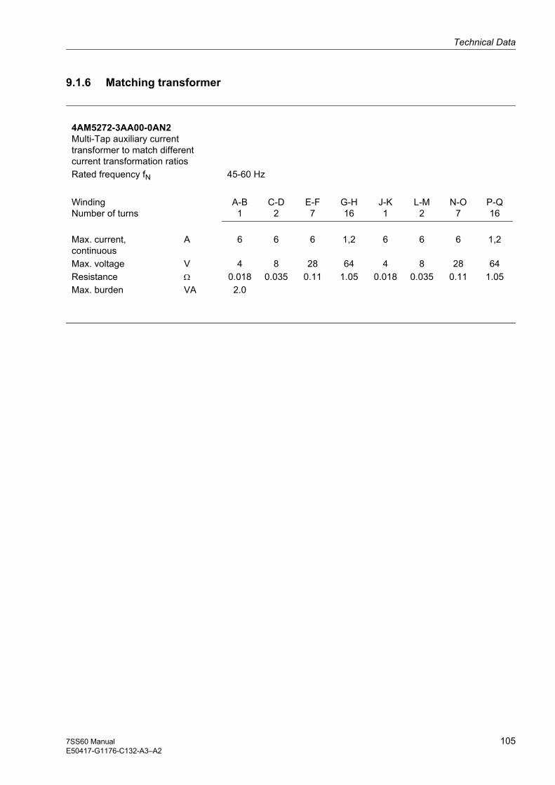
Technical Data
1057SS60 ManualE50417-G1176-C132-A3–A2
9.1.6 Matching transformer
4AM5272-3AA00-0AN2 Multi-Tap auxiliary current transformer to match different current transformation ratios Rated frequency fN 45-60 Hz
WindingNumber of turns
A-B1
C-D2
E-F7
G-H16
J-K1
L-M2
N-O7
P-Q16
Max. current, continuous
A 6 6 6 1,2 6 6 6 1,2
Max. voltage V 4 8 28 64 4 8 28 64Resistance Ω 0.018 0.035 0.11 1.05 0.018 0.035 0.11 1.05Max. burden VA 2.0

Technical Data
106 7SS60 ManualE50417-G1176-C132-A3–A2
9.2 Electrical tests
CE conformity, regulations
This product complies with the directive of the Council of the European Communities on the approximation of the laws of the member states relating to electromagnetic compatibility (EMC Council Directive 89/336/EEC) and concerning electrical equipment for use within certain voltage limits (Low-voltage Directive 73/23/EEC).
The product conforms with international standards of series IEC 60255 and the German standard DIN 57 435 /Part 303.
This product was developed and manufactured for utilization in industrial installations according to the EMC standards.
This conformity is proved by tests conducted by Siemens AG in accordance with Article 10 of the Council Directive in agreement with the generic standards EN 50081 and EN 50082 for EMC directive, and with the standards EN 60255-6 for the low-voltage directive.
Insulation testsStandards: IEC 60255-5; ANSI/IEEE C37.90.0
High voltage test (routine test), measuring input Id and relay outputs
High voltage test (routine test), auxiliary voltage input and RS485 interface, binary inputs and measuring input IR
Impulse voltage test (type test), all circuits, class III
2.5 kV (rms); 50 Hz
DC 3.5 kV
5 kV (peak); 1.2/50 μs; 0.5 J; 3 positive and 3 negative pulses in intervals of 5 s
EMC tests against radio disturbances (type tests)IEC 60255-6, IEC 60255-22(international product standards)EN 50082-2 (technical generic standard)DIN VDE 57435 part 303 (German product standard for protection devices)
High-frequency testIEC 60255-22-1, DIN VDE 0435 part 303; class III
Discharge of static electricityIEC 60255-22-2; IEC 61000-4-2; Klasse IV
Exposure to HF field, non-modulatedIEC 60255-22-3 (report); class III
Exposure to HF field, amplitude-modulatedIEC 61000-4-3; class III
Exposure to HF field, pulse-modulatedIEC 61000-4-3/ENV 50204; class III
Fast transient disturbance / burstIEC 60255-22-4; IEC 61000-4-4; class III
2.5 kV (peak); 1 MHz; t = 15 μs; 400 pulses per s; test duration 2 s
8 kV discharge of contacts; 15 kV discharge into air; both polarities; 150 pF; Rl = 330 Ω
10 V/m; 27 to 500 MHz
10 V/m; 80 to 1 000 MHz; 80 % AM; 1 kHz
10 V/m; 900 MHz; repetition frequency 200 Hz; ED 50 %
4 kHz; 5/50 ns; 5 kHz, burst duration = 15 ms; repetition rate 300 ms; both polarities; Rl = 50 Ω; test duration 1 min

Technical Data
1077SS60 ManualE50417-G1176-C132-A3–A2
High-energy pulse(SURGE), IEC 61000-4-5, installation class 3
HF on lines, amplitude-modulated IEC 61000-4-6; class III
Power system-frequency magnetic fieldIEC 61000-4-8; class IVIEC 60255-6
Auxiliary voltageLongitudinal test 2 kV; 12 Ω; 9 μFTransversal test 1 kV; 2 Ω; 18 μFMeasuring inputs, binary inputs and relay outputs:Longitudinal test: 2 kV; 42 Ω; 0.5 μFTransversal test: 1 kV; 42 Ω; 0.5 μF 10 V; 150 kHz to 80 MHz; 80 % AM; 1 kHz
30 A/m; continuous; 300 A/m for 3 s; 50 Hz; 0.5 mT
Further EMC tests against radio disturbances (type tests)
Oscillatory Surge Withstand CapabilityANSI/IEEE C37.90.1
Fast Transient Surge Withstand CapabilityANSI/IEEE C37.90.1
Radiated Electromagnetic InterferenceANSI/IEEE C37.90.2
Damped oscillationsIEC 61000-4-12IEC 60694
2.5 to 3 kV (peak); 1 to 1.5 MHz; damped wave; 50 pulses per s; duration 2 s; Ri = 150 to 200 Ω
4 to 5 kV; 10/150 ns; 50 pulses per s; both polarities; duration 2 s; Ri = 80 Ω
35 V/m; 25 to 1000 MHz
2.5 kV (peak, alternating polarity); 100 kHz; 1, 10 and 50 MHz;damped wave; Ri = 50 Ω
EMC tests for radio transmission EN 50081-* (technical generic standard)
Radio disturbance voltage on lines, only auxiliary voltage, EN 55022, DIN VDE 0878 part 22, IEC CISPR 22
Disturbance field intensityEN 55011, DIN VDE 0875 part 11, IEC CISPR 11
150 kHz to 30 MHz, limit value class B
30 to 1 000 MHz, limit value class A

Technical Data
108 7SS60 ManualE50417-G1176-C132-A3–A2
9.3 Mechanical tests
Vibration and shock during operationIEC 60255-21-1 IEC 60068-2
Vibration IEC 60255-21-1, class II IEC 60068-2-6
Shock IEC 60255-21-2, class I IEC 60 068–2–27
Seismic vibration IEC 60255-21-3, class 1 IEC 60068-3-3 horizontal axis
vertical axis
sinusoidal10 to 60 Hz, ±0.075 mm amplitude60 to 150 Hz; 1 g acceleration sweep rate 1 octave/min 20 cycles in 3 orthogonal axes
half sinusoidal acceleration 5 g; duration 11 ms 3 shocks in each direction of the 3 orthogonal axes
sinusoidal
1 to 8 Hz: ±3.5 mm amplitude8 to 35 Hz: 1 g acceleration
1 to 8 Hz: ±1.5 mm amplitude8 to 35 Hz: 0.5 g acceleration
frequency sweep 1 octave/min 1 cycle in 3 orthogonal axes
Vibration and shock during transportIEC 60255-21 IEC 60068-2
Vibration IEC 60255-21-1, class II IEC 60068-2-6
Shock IEC 60255-21-2, class 1 IEC 60068-2-27
Continuous shock IEC 60255-21-2, class 1 IEC 60068-2-29
sinusoidal5 to 8 Hz: ±7.5 mm Amplitude 8 to 150 Hz: 2 g acceleration sweep rate 1 octave/min20 cycles in 3 orthogonal axes
half sinusoidalacceleration 15 g; duration 11 ms 3 shocks in each direction of the 3 orthogonal axes
half sinusoidal acceleration 10 g; duration 16 ms 1000 shocks in each direction of the 3 orthogonal axes

Technical Data
1097SS60 ManualE50417-G1176-C132-A3–A2
9.4 Climatic stress test
Climatic stress testEN 60255-6IEC 60255-6
Permissible ambient temperaturein service
for storage
during transport
Storage and transport with standards works packing
-20 to +45 °C
-25 to +55 °C
-25 to +70 °C
Humidity in service mean value per year ≤ 75 % relative humidity, on 56 days per year 95 % relative humidity; condensation not permissible!
We recommend to install the devices so that they are not subject to direct sunlight and strong fluctuations in temperature which could lead to moisture condensation.

Technical Data
110 7SS60 ManualE50417-G1176-C132-A3–A2
9.5 Service conditions
The relay is designed for use in industrial environment, for installation in standard relay rooms and compartments so that with proper installation electro-magnetic compatibility (EMC) is ensured. the following should also be heeded:
• All contactors and relays which operate in the same cubicle or on the same relay panel as the digital protection equipment should, as a rule, be fitted with suitable spike quenching elements.
• All external connection leads in substations from 100 kV upwards should be screened with a screen capable of carrying power currents and earthed at both sides. No special measures are normally necessary for substations of lower voltages.
• It is not permissible to withdraw or insert individual modules under voltage. In the withdrawn condition., some components are electrostatically endangered; during handling the standards for electrostatically endangered components must be observed. The modules are not endangered when plugged in.
Warning! The device is not designed for used in residential environment as defined in EN 50081.

Technical Data
1117SS60 ManualE50417-G1176-C132-A3–A2
9.6 Dimensions
Measuring system7570 71 +2
255.
8 ±
0.3
245
+ 1
6
Side view
Rear view
Panel cutout
244
266
29.5 172 37
Mounting plate
56.5 ± 0.3
7.35.4
5 orM4
Dimensions in mm
Figure 9-1 Housing 7XP20 of the 7SS601 measuring system for panel or cubicle flush mounting

Technical Data
112 7SS60 ManualE50417-G1176-C132-A3–A2
Peripheral module housing
Rear view
221 +2
5 or M4
6
Panel cutout
255.
8 ±
0.3
245
+ 1
180 ± 0.5 206.5 ± 0.3
13.27.3
5.4
Side view
244
266
229.5 172
Mounting plate 220225
Dimensions in mm
dependent on min. bending radius of the used wires
22
Figure 9-2 Housing 7XP204 of the peripheral modules for panel or cubicle flush mounting

Technical Data
1137SS60 ManualE50417-G1176-C132-A3–A2
Matching transformer / Summation current matching transformer 4AM5120
Varistor
Dimensions in mm
Mountingtemplate
Figure 9-3 Matching transformer and summation current matching transformer 4AM5120
1 Terminal 8WA9200 Siemens Cross-section:Single-wire 0.5 mm2 to 6 mm2
Fine-wire 0.5 mm2 to 4 mm2
Current rating: 21 A Number of terminals depending on design
2 Flat connector DIN46244-A6.3-0.8, Protective-grounding terminal
3 Fixing racket for DIN rail mounting

Technical Data
114 7SS60 ManualE50417-G1176-C132-A3–A2
Matching transformer 4AM5272
Dimensions in mm
Mountingtemplate
Figure 9-4 Matching transformer 4AM5272
1 Terminal Cross-section:Single-wire 0.5 mm2 to 6 mm2
Fine-wire 0.5 mm2 to 4 mm2
2 Flat connector DIN46244-A6.3-0.8, Protective-grounding terminal
1157SS60 ManualE50417-G1176-C132-A3
Appendix AThis appendix is mainly a reference for experienced users. It contains ordering infor-mation, general diagrams and connection diagrams, and tabular listings of all settings and system data for the full scope of device functions.
A.1 Ordering data and accessories 116
A.2 Block diagram - Measuring system 119
A.3 Block diagrams - Peripheral modules 120
A.4 Jumper settings for the measuring system 123
A.5 Jumper settings for the peripheral modules 125
A.6 Operating tree 128
A.7 Overview of parameters 133
A.8 List of information 134

Appendix
116 7SS60 ManualE50417-G1176-C132-A3
A.1 Ordering data and accessories
Table A-1 Selection and ordering data
Order No.
Measuring system 7SS601 ❏ – ❏ ❏ A ❏ 0 – 0 A A 0
Rated current/frequency
100 mA, AC 50, 60 Hz 0
100 mA, AC 16.7 Hz 6
Rated auxiliary voltage of converter
DC 24 V to DC 48 V 2
DC 60 V to DC 125 V 4
DC 220 V to DC 250 V, AC 115 V 5
Mechanical design
In 7XP20 1/6 19" housing, for panel or cubi-cle flush mounting E
Measuring system
Standard measuring system 0
Order No.
Restraint/
command output module 7TM700 0 – 0 A A 0 0 – 0 A A 0
Rated auxiliary voltage
DC 48 V, DC 60 V / DC 110 V, DC 125 V / DC 220 V, DC 250 V
settable
Order No.
Preferential treatment/
Isolator replica module 7TR710 0 – ❏ A A 0 0 – 0 A A 0
Rated auxiliary voltage
DC 48 V to DC 60 V 3
DC 110 V to DC 125 V 4
DC 220 V to DC 250 V 5

Order No.
Command output module 7TS720 0 – 0 A A 0 0 – 0 A A 0
Rated auxiliary voltage
DC 48 V, DC 60 V / DC 110 V, DC 125 V / DC 220 V, DC 250 V
settable
Order No.
Housing for peripheral modules 7XP204 1 – 2 M A 0 0 – 0 A A 0
Appendix
1177SS60 ManualE50417-G1176-C132-A3

Accessories Order No.
Copper cable
between PC (9-pin female connector)
and converter/protection device 7XV5100-2
RS232 - RS485 converter
with power supply unit for AC 230 V 7XV5700-0AA0
with power supply unit for AC 110 V 7XV5700-1AA0
Converter
Full duplex fiber optic cable - RS485
Auxiliary voltage: DC 24 V to 250 V, AC 110/230 V
1 channel FSMA plug 7XV5650-0AA0
ST plug 7XV5650-0BA0
2 channels FSMA plug 7XV5651-1AA0
ST plug 7XV5651-1BA0
Communication software DIGSI4 (incl. DIGSI 3)
English/German/French 7XS5400-0AA00
Graphic evaluation software SIGRA 4
English/German/French 7XS5410-0AA00
Remote control software DIGSI REMOTE 4
English/German/French 7XS5440-0AA00
Summation current/matching transformer
1 A, 50/60 Hz 4AM5120-3DA00-0AN2
5 A, 50/60 Hz 4AM5120-4DA00-0AN2
Matching transformer
1 A, 50/60 Hz 4AM5120-1DA00-0AN2
5 A, 50/60 Hz 4AM5120-2DA00-0AN2
1 A, 5 A, 50/60 Hz 4AM5272-3AA00-0AN2
1 A, 16.7 Hz 4AM5120-1DB00-0AN2
5 A, 16.7 Hz 4AM5120-7BA00-0AN0
Test adapter for 7SS60 7XV6010-0AA00
connector for peripheral modules (spare part) W73078-B9005-A710
Angle bracket (2 pieces) C73165-A63-D200-1
Extractio tool for connector W73078-Z9005-A710
Appendix
118 7SS60 ManualE50417-G1176-C132-A3

Appendix
1197SS60 ManualE50417-G1176-C132-A3
A.2 Block diagram - Measuring system
7SS601
Figure A-1 Block diagram of the 7SS601 measuring system (default setting of binary inputs, command and signal relays as delivered)

Appendix
120 7SS60 ManualE50417-G1176-C132-A3
A.3 Block diagrams - Peripheral modules
Restraint/ command output module 7TM700 Attention! All relay coils depend on polarity
Figure A-2 Block diagram for 7TM700 restraint/command output module

Appendix
1217SS60 ManualE50417-G1176-C132-A3
Preferential treatment/ isolator replica module 7TR710 Attention! All relay coils depend on polarity
Figure A-3 Block diagram of 7TR710 preferential treatment/isolator replica module

Appendix
122 7SS60 ManualE50417-G1176-C132-A3
Command output module 7TS720 Attention! All relay coils depend on polarity
Figure A-4 Block diagram of 7TS720 command output module

Appendix
1237SS60 ManualE50417-G1176-C132-A3
A.4 Jumper settings for the measuring system
7SS601
X12
1
X304321
X28
3
12
23
X11123
X6
LH
X8
LH
X7
LH
X20321
X21
F1
Figure A-5 Location of the jumpers in the 7SS601 measuring system (delivery status)
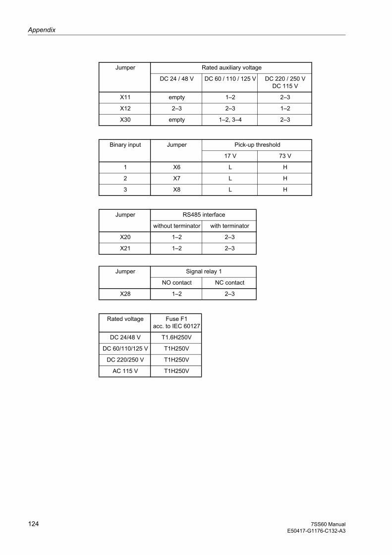
Jumper Rated auxiliary voltage
DC 24 / 48 V DC 60 / 110 / 125 V DC 220 / 250 VDC 115 V
X11 empty 1–2 2–3
X12 2–3 2–3 1–2
X30 empty 1–2, 3–4 2–3
Binary input Jumper Pick-up threshold
17 V 73 V
1 X6 L H
2 X7 L H
3 X8 L H
Jumper RS485 interface
without terminator with terminator
X20 1–2 2–3
X21 1–2 2–3
Jumper Signal relay 1
NO contact NC contact
X28 1–2 2–3
Rated voltage Fuse F1acc. to IEC 60127
DC 24/48 V T1.6H250V
DC 60/110/125 V T1H250V
DC 220/250 V T1H250V
AC 115 V T1H250V
Appendix
124 7SS60 ManualE50417-G1176-C132-A3

Appendix
1257SS60 ManualE50417-G1176-C132-A3
A.5 Jumper settings for the peripheral modules
Restraint/ command output module 7TM700
220/250V110/125V
48/60V
X214321
220/250V110/125V48/60V
X224321
220/250V110/125V48/60V
X234321
220/250V110/125V48/60V
X244321
220/250V110/125V48/60V
X254321
X1 X2
Figure A-6 Location of the jumpers on the 7TM700 restraint/command output module (delivery status)
Relay No. Jumper Rated auxiliary voltage
DC 24 / 48 V DC 110 / 125 V DC 220 / 250 V
K1 X21 1–2 2–3 3–4
K2 X22 1–2 2–3 3–4
K3 X23 1–2 2–3 3–4
K4 X24 1–2 2–3 3–4
K5 X25 1–2 2–3 3–4
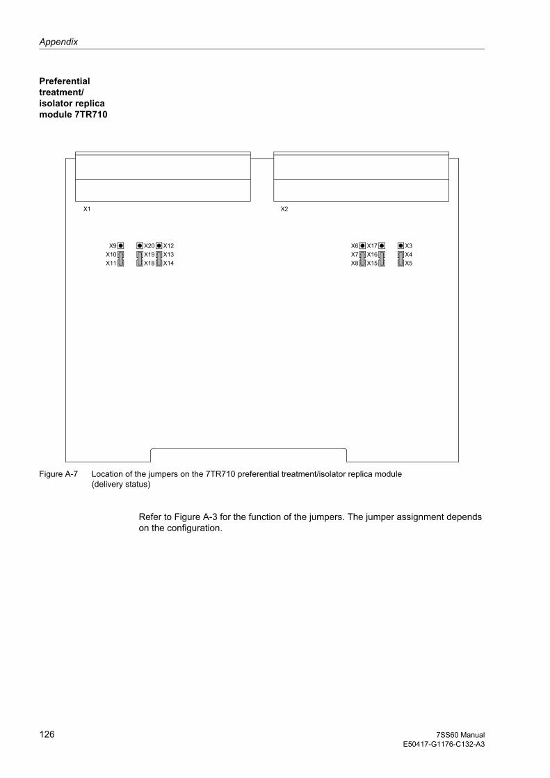
Appendix
126 7SS60 ManualE50417-G1176-C132-A3
Preferential treatment/ isolator replica module 7TR710
X10X9
X11X19X18
X20X13X14
X12X4X5
X3X16X17
X15X7X6
X8
X1 X2
Figure A-7 Location of the jumpers on the 7TR710 preferential treatment/isolator replica module (delivery status)
Refer to Figure A-3 for the function of the jumpers. The jumper assignment depends on the configuration.

Appendix
1277SS60 ManualE50417-G1176-C132-A3
Command output module 7TS720
220/250V110/125V48/60V
X214321
220/250V110/125V48/60V
X224321
220/250V110/125V48/60V
X234321
220/250V110/125V48/60V
X244321
220/250V110/125V48/60V
X254321
220/250V110/125V48/60V
X264321
220/250V110/125V48/60V
X274321
220/250V110/125V48/60V
X284321
X1 X2
Figure A-8 Location of the jumpers on the 7TS720 command output module (delivery status)
Relay No. Jumper Rated auxiliary voltage
DC 48 / 60 V DC 110 / 125 V DC 220 / 250 V
K1 X21 1–2 2–3 3–4
K2 X22 1–2 2–3 3–4
K3 X23 1–2 2–3 3–4
K4 X24 1–2 2–3 3–4
K5 X25 1–2 2–3 3–4
K6 X26 1–2 2–3 3–4
K7 X27 1–2 2–3 3–4
K8 X28 1–2 2–3 3–4

Appendix
128 7SS60 ManualE50417-G1176-C132-A3
A.6 Operating tree
The following operating tree gives you an overview of the address blocks and setting parameters of the 7SS601 busbar protection system. It shows the operating sequenc-es that must be followed to make a specific selection.
Table A-2 Operating tree of the 7SS601
1st level 2nd level 3rd level 4th level 5th level
7SS601V3.10
7SS601
PARAME. 01 POWERSYST.DAT
01 FREQ
01 T-TRP
01 L.Out
10BUSBARPROTECT.
10BPStat
10 Id>
10 K fac
10 TrpDly
13 IDIFFSUPERV
13Id sup
13Id thr
60 MARSH 61 MARSHBIN.INP
61 MARSHBI1
61 BI1 1
:
61 BI1 10

Appendix
1297SS60 ManualE50417-G1176-C132-A3
61 MARSHBI2
61 BI2 1
:
61 BI2 10
61 MARSHBI3
61 BI3 1
:
61 BI3 10
62 MARSHSIG.REL
62 MARSHSIG.RE 2
62SIG 1
:
62SIG20
62 MARSHSIG.RE 3
62SIG3 1
:
62SIG320
63 MARSHLED
63 MARSHLED 1
63LED1 1
:
63LED120
63 MARSHLED 2
63LED2 1
:
63LED220
63 MARSHLED 3
63LED3 1
:
63LED320
Table A-2 Operating tree of the 7SS601
1st level 2nd level 3rd level 4th level 5th level

Appendix
130 7SS60 ManualE50417-G1176-C132-A3
63 MARSHLED 4
63LED4 1
:
63LED420
64 MARSHCMD.REL
64 MARSHCMD.RE 2
64CMD2 1
:
64CMD220
71INT.OP 71 LANGUA
72 INTERFACE
72DEVICE
72FEEDER
72SUBSTA
72PC-INT
72 GAPS
72PCBAUD
72PARITY
74 FAULTRECORDER
74 T-MAX
74 T-PRE
74 T-POS
Table A-2 Operating tree of the 7SS601
1st level 2nd level 3rd level 4th level 5th level
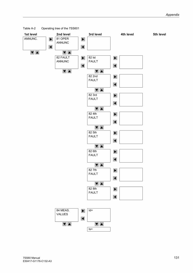
Appendix
1317SS60 ManualE50417-G1176-C132-A3
ANNUNC. 81 OPERANNUNC
82 FAULTANNUNC
82 lstFAULT
82 2ndFAULT
82 3rdFAULT
82 4thFAULT
82 5thFAULT
82 6thFAULT
82 7thFAULT
82 8thFAULT
84 MEAS.VALUES
Id=
Is=
Table A-2 Operating tree of the 7SS601
1st level 2nd level 3rd level 4th level 5th level

Appendix
132 7SS60 ManualE50417-G1176-C132-A3
ADDITIONFUNCTION
TIMESETTING
TIMESETTING
DATE
TIME
TESTAIDS
I/O STAT BI-STAT
RE-STAT
LED STATUS
MONITOR
Table A-2 Operating tree of the 7SS601
1st level 2nd level 3rd level 4th level 5th level

Appendix
1337SS60 ManualE50417-G1176-C132-A3
A.7 Overview of parameters
DIGSIaddr.
Parameter Possible settings Default setting Explanation
1101 01 FREQ 50 Hz60 Hz
50 Hz Rated frequency of power system
1134 01 T-TRP 0.01s to 32.00 s 0.15 s Minimum duration of TRIP command
1135 01 L.Out OFFONON/butt.
OFF Lockout function
1501 10BUSBAR PROTECT.
ONOFFBLO.TRP
ON Busbar protection function
1505 10Id> 0.20 Ino1 to 2.50 Ino1 1.00 Ino1 Minimum threshold for differential current
1506 10K fac 0.25 to 0.80 0.60 Sensitivity to internal faults
1511 10 TrpDly 0.00 to 10.00 s 0.00 s Time delay of trip
1801 13Id Sup bl/relBPbl/ackBPALRMonlyOFF
bl/relBP State of supervision of the differential current function
1802 13Id thr 0.10 Ino1 to 1.00 Ino1 0.15 Ino1 Threshold of differential current supervision
7101 71LANGUA ENGLISHDEUTSCH
ENGLISH Selection of the operating language
7201 72DEVICE minimum setting:..... .....1maximum setting:.....254
1 ID number of the device within the substation
7202 72FEEDER minimum setting:..... .....1maximum setting:.....254
1 Number of feeder within the substation (feeder address)
7203 72SUBSTA minimum setting:..... .....1maximum setting:.....254
1 ID number of substation, if more than one substation can be addressed
7211 72 PC-INT DIGSI V3ASCII
DIGSI V3 Data format for the interface
7214 72 GAPS minimum setting:.....0.0 smaximum setting:....5.0 s
1.0 s Maximum permissible transmission gap between telegrams for modem transmission
7215 72PCBAUD 1200 Baud2400 Baud4800 Baud9600 Baud19200 Baud
9600 Baud Transmission baud rate for serial PC- interface
7216 72 PARITY DIGSI V38O18N28N1
DIGSI V3 Parity of transmission telegrams
7410 74-T MAX 0.20 s to 5.00 s 1.50 s Maximum time period of a fault recording
7411 74 T-PRE 0.05 s to 1.50 s 0.30 s Pre-trigger time for fault recording
7412 74 T-POS 0.05 s to 1.50 s 0.20 s Post-fault time for fault recording
1) Ino: normalized rated current; Ino = 100 mA with a symmetrical rated current flowing at the primary side
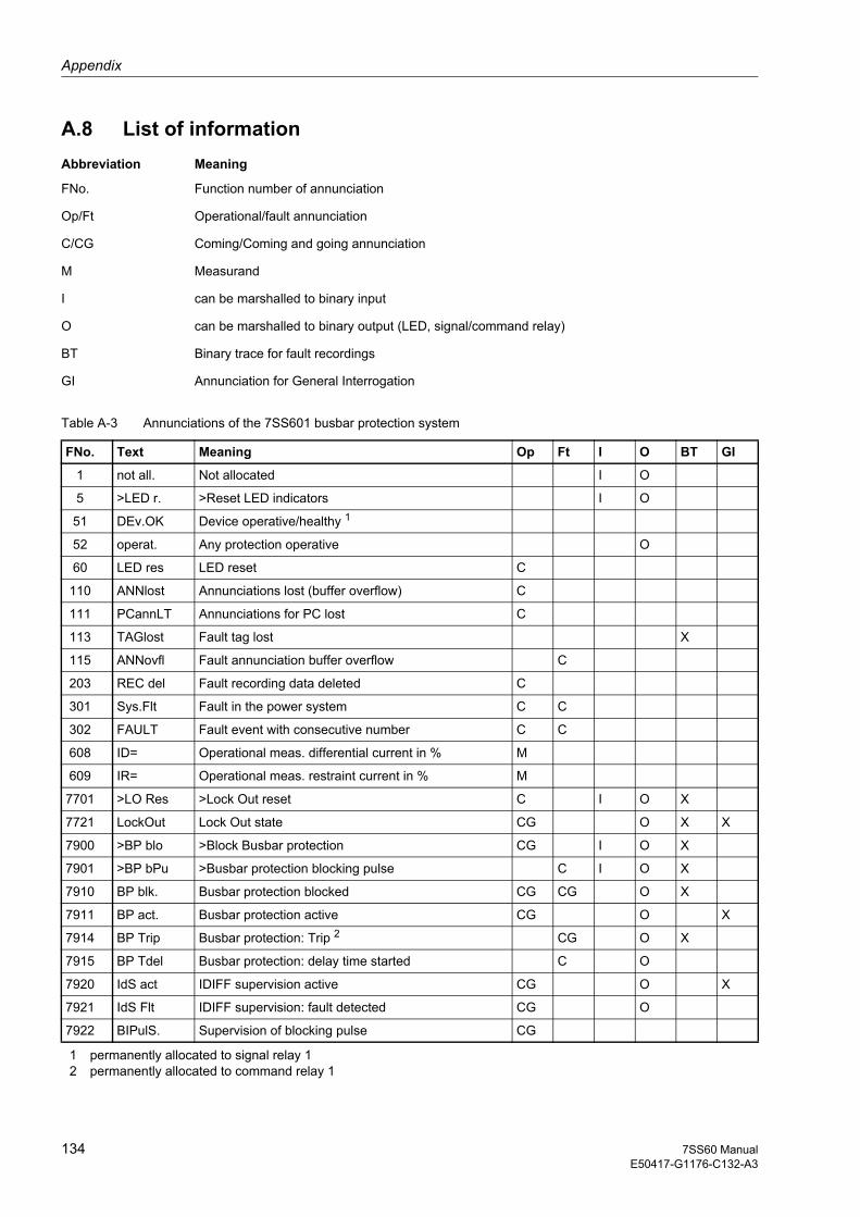
Appendix
134 7SS60 ManualE50417-G1176-C132-A3
A.8 List of information Abbreviation Meaning
FNo. Function number of annunciation
Op/Ft Operational/fault annunciation
C/CG Coming/Coming and going annunciation
M Measurand
I can be marshalled to binary input
O can be marshalled to binary output (LED, signal/command relay)
BT Binary trace for fault recordings
GI Annunciation for General Interrogation
Table A-3 Annunciations of the 7SS601 busbar protection system
FNo. Text Meaning Op Ft I O BT GI
1 not all. Not allocated I O
5 >LED r. >Reset LED indicators I O
51 DEv.OK Device operative/healthy
1 permanently allocated to signal relay 12 permanently allocated to command relay 1
1
52 operat. Any protection operative O
60 LED res LED reset C
110 ANNlost Annunciations lost (buffer overflow) C
111 PCannLT Annunciations for PC lost C
113 TAGlost Fault tag lost X
115 ANNovfl Fault annunciation buffer overflow C
203 REC del Fault recording data deleted C
301 Sys.Flt Fault in the power system C C
302 FAULT Fault event with consecutive number C C
608 ID= Operational meas. differential current in % M
609 IR= Operational meas. restraint current in % M
7701 >LO Res >Lock Out reset C I O X
7721 LockOut Lock Out state CG O X X
7900 >BP blo >Block Busbar protection CG I O X
7901 >BP bPu >Busbar protection blocking pulse C I O X
7910 BP blk. Busbar protection blocked CG CG O X
7911 BP act. Busbar protection active CG O X
7914 BP Trip Busbar protection: Trip 2 CG O X
7915 BP Tdel Busbar protection: delay time started C O
7920 IdS act IDIFF supervision active CG O X
7921 IdS Flt IDIFF supervision: fault detected CG O
7922 BIPulS. Supervision of blocking pulse CG
1357SS60 ManualE50417-G1176-C132-A3
Index
AAccessories 116Application scope 16Auxiliary voltage 82, 84
BBaud rate 46Block 81 77Block 82 78Block 84 78Block diagram
Peripheral modules 120Block diagrams
Measuring system 119Busbar protection 70
CCharacter format 46Check
Electrical 27Isolator replica 86Isolator status feedback signals 86Rated data 27Trip circuits 86
CheckingCurrent transformer circuits 86Infeed circuits 86
Climatic stress test 109Codeword entry 36Commissioning 85Control voltage for binary inputs 82
DData format 45Date and time
Setting 47Date/time
Readout 79Design 13Device address 45Device data 96Differential current
Pick-up value 70Differential current supervision 72
Pick-up threshold 72Dimensions
Matching transformers 113Measuring system 111Peripheral modules housing 112Summation current transformers 113
EEarth current sensitivity
Increased 60Normal 57, 64
FFault events 78Fault recording
Times 74Features 18Feeder address 45
IIndication 3Indication of conformity 3Input currents
Directional check 88Installation
Measuring system 82Peripheral modules 83
Instructions 4
JJumper settings
Measuring system 123Peripheral modules 125
LLEDs 76List of information 134Lockout function 66
MManual
Aim 3Scope of validity 3Target audience 3
Marshalling

Index
136 7SS60 ManualE50417-G1176-C132-A3
Binary inputs 40Command relays 44General 37LEDs 43Signal relays 41
Matching transformers 64, 65Measured values 78Measurement method
Basic principle 50Output circuit 52Restraint 53Supervision 52
Measuring principle 12Measuring system
Connection system 21Housing 20
OOperating language
Change 37Operating tree 128Operation
from a PC 30from membrane keypad 30from the keyboard 29Prerequisites 31
Operational annunciations 77Ordering code 27Ordering data 116Output of events and measured values 76Overview of parameters 133
PPeripheral modules
Connection system 23Housing 22Slots 23
Pick-up characteristic 12
QQualified personnel 4
RRated frequency 66Rated system frequency 67Repair 94Replacing the mini-fuse 92Restraint 12Restraint factor 70Return of device to factory 94Routine checks 91
SSerial interface 45Service conditions 110Storage 32Substation address 45Support
Additional support 3Symbol conventions 5
TTesting
Binary inputs 79LEDs 80Signal relays 80
TestsElectrical 106Mechanical 108
Training courses 3Transmission gaps 45Troubleshooting
Measuring system 92Peripheral modules 93
Typographic conventions 5
UUnpacking and repacking 26
WWarnings 4