design and commissioning of a 1mw pilot-scale oxy-fuel ...ieaghg.org/docs/general_docs/5oxy...
TRANSCRIPT

Design and commissioning of a 1MWth pilot-scale oxy-fuel circulating fluidized bed with high
oxygen concentration
LI Haoyu, LI Shiyuan*, REN Qiangqiang,Li Wei, LIU Jingzhang
Institute of Engineering Thermophysics (IET)Chinese Academy of Sciences (CAS)11 Beisihuanxi Road, Beijing, China
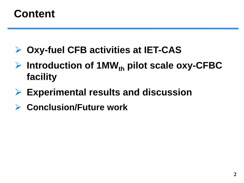
Content
Oxy-fuel CFB activities at IET-CAS Introduction of 1MWth pilot scale oxy-CFBC
facility Experimental results and discussion Conclusion/Future work
2
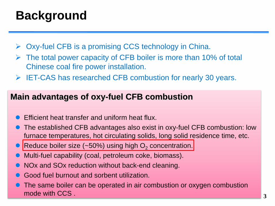
Background
Oxy-fuel CFB is a promising CCS technology in China. The total power capacity of CFB boiler is more than 10% of total
Chinese coal fire power installation. IET-CAS has researched CFB combustion for nearly 30 years.
3
Main advantages of oxy-fuel CFB combustion
Efficient heat transfer and uniform heat flux. The established CFB advantages also exist in oxy-fuel CFB combustion: low
furnace temperatures, hot circulating solids, long solid residence time, etc. Reduce boiler size (~50%) using high O2 concentration. Multi-fuel capability (coal, petroleum coke, biomass). NOx and SOx reduction without back-end cleaning. Good fuel burnout and sorbent utilization. The same boiler can be operated in air combustion or oxygen combustion
mode with CCS .
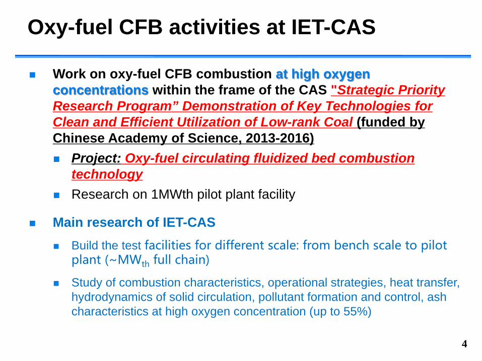
Oxy-fuel CFB activities at IET-CAS
Work on oxy-fuel CFB combustion at high oxygen concentrations within the frame of the CAS "Strategic Priority Research Program” Demonstration of Key Technologies for Clean and Efficient Utilization of Low-rank Coal (funded by Chinese Academy of Science, 2013-2016) Project: Oxy-fuel circulating fluidized bed combustion
technology Research on 1MWth pilot plant facility
Main research of IET-CAS Build the test facilities for different scale: from bench scale to pilot
plant (~MWth full chain)
Study of combustion characteristics, operational strategies, heat transfer, hydrodynamics of solid circulation, pollutant formation and control, ash characteristics at high oxygen concentration (up to 55%)
4

Oxy-fuel CFB test facilities at IET-CAS
5
Bench-scaleBFBC 100mm
Bench-scaleCFBC 100mm 30-
50kWO2: 21-50%
Bench-scaleCFBC 140mm 0.1MW
O2: 35-55%
Pilot PlantCFBC 420mm 1MW
O2: 21-50%
Scale-up
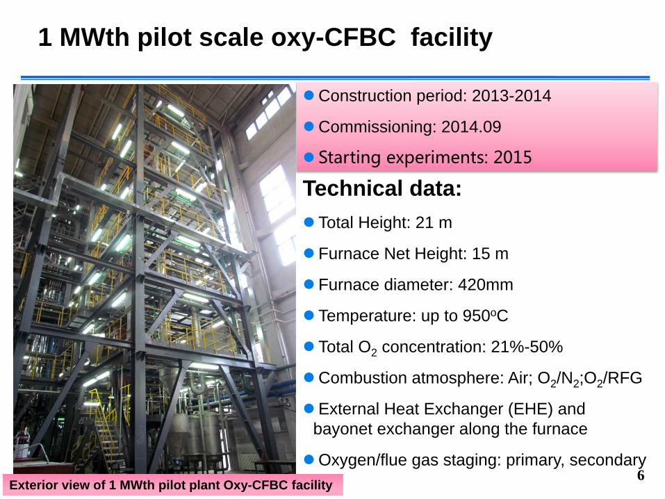
1 MWth pilot scale oxy-CFBC facility
Technical data: Total Height: 21 m
Furnace Net Height: 15 m
Furnace diameter: 420mm
Temperature: up to 950oC
Total O2 concentration: 21%-50%
Combustion atmosphere: Air; O2/N2;O2/RFG
External Heat Exchanger (EHE) and bayonet exchanger along the furnace
Oxygen/flue gas staging: primary, secondary 6
Construction period: 2013-2014
Commissioning: 2014.09
Starting experiments: 2015
Exterior view of 1 MWth pilot plant Oxy-CFBC facility

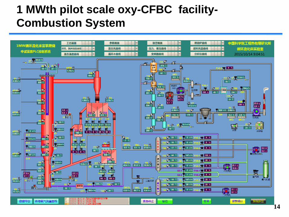
1 MWth pilot scale oxy-CFBC facility-Combustion System
7
Schematic diagram of 1 MWth pilot plant Oxy-CFBC facility
CFB combustion system
flue gas cooling and cleaning system
dry flue gas recycle system
gas mixing and supplying system
measurement and control system

1 MWth pilot scale oxy-CFBC facility-Combustion System
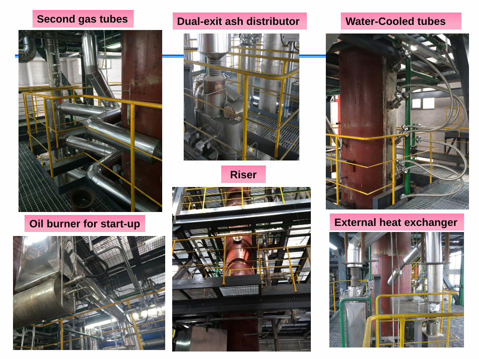
Technical data:Refractory furnace and cyclone
Furnace net height: 15 m
Furnace diameter: 280mm(bottom),420mm (top)
Temperature: up to 950oC
Water Cooling Bayonet (Vertical: one, 8m; declining: 4 groups, reach the axis)
Dual-exit ash distributor
Loop seal
External Heat Exchanger (EHE)
Oxygen/flue gas staging: primary, secondary(four layers)
8Schematic diagram of 1 MWth pilot plant Oxy-CFBC facility
9
Second gas tubes
Oil burner for start-up
Water-Cooled tubes
Riser
Dual-exit ash distributor
External heat exchanger

1 MWth pilot scale oxy-CFBC facility-Combustion System
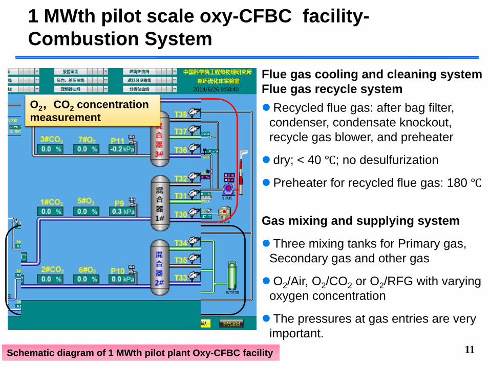
Flue gas cooling and cleaning systemFlue gas recycle systemRecycled flue gas: after bag filter,
condenser, condensate knockout, recycle gas blower, and preheater
dry; < 40 ℃; no desulfurization
Preheater for recycled flue gas: 180 ℃
10Schematic diagram of 1 MWth pilot plant Oxy-CFBC facility
Gas mixing and supplying system
Three mixing tanks for Primary gas, Secondary gas and other gas
O2/Air, O2/CO2 or O2/RFG with varying oxygen concentration
The pressures at gas entries are very important.
1 MWth pilot scale oxy-CFBC facility-Combustion System
11Schematic diagram of 1 MWth pilot plant Oxy-CFBC facility
Gas mixing and supplying system
Three mixing tanks for Primary gas, Secondary gas and other gas
O2/Air, O2/CO2 or O2/RFG with varying oxygen concentration
The pressures at gas entries are very important.
O2,CO2 concentration measurement
Flue gas cooling and cleaning systemFlue gas recycle systemRecycled flue gas: after bag filter,
condenser, condensate knockout, recycle gas blower, and preheater
dry; < 40 ℃; no desulfurization
Preheater for recycled flue gas: 180 ℃
1 MWth pilot scale oxy-CFBC facility-Combustion System
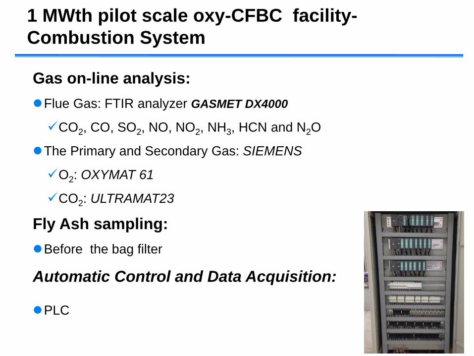
Gas on-line analysis:Flue Gas: FTIR analyzer GASMET DX4000
CO2, CO, SO2, NO, NO2, NH3, HCN and N2O
The Primary and Secondary Gas: SIEMENS
O2: OXYMAT 61
CO2: ULTRAMAT23
Fly Ash sampling:Before the bag filter
Automatic Control and Data Acquisition:
PLC
12

13
Recirculation fan
Gas flow meter
Gas mixing tanks
Oxygen and CO2 on-line analysis Liquid oxygen tank
Bag filter
14
1 MWth pilot scale oxy-CFBC facility-Combustion System
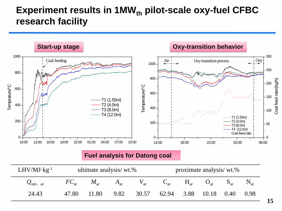
Experiment results in 1MWth pilot-scale oxy-fuel CFBC research facility
15
Start-up stage Oxy-transition behavior
0
200
400
600
800
1000
10:0007:0004:0001:0022:0019:0016:0010:00
Tem
prat
ure/°C
T1 (1.55m) T2 (4.0m) T3 (8.0m) T4 (12.0m)
13:00
Coal feeding
0
200
400
600
800
1000
Oxy
T1 (1.55m) T2 (4.0m) T3 (8.0m) T4 (12.0m) Coal feed rate
06:0002:0022:0018:00Te
mpe
ratu
re/°C
14:00
Air Oxy-transition process
0
50
100
150
200
250
300
Coa
l fee
d ra
te/(k
g/h)
LHV/MJ·kg-1 ultimate analysis/ wt.% proximate analysis/ wt.%
Qnet,ar FCar Mar Aar Var Car Har Oar Sar Nar
24.43 47.80 11.80 9.82 30.57 62.94 3.88 10.18 0.40 0.98
Fuel analysis for Datong coal

Experiment results in 1MWth pilot-scale oxy-fuel CFBC research facility
16
Experimental conditions
Parameter unit
Datong coal
Air 30%O2/RFG 40% O2/RFG 50% O2/RFG
average bed temperature ℃ 857 865 873 884
average cyclone temperature ℃ 835 848 856 874
average loop seal temperature ℃ 816 835 841 865
average external heat exchanger
temperature℃ ------ 641 653 671
fuel feeding rate kg/h 88 162 183 198thermal power MW 0.58 1.03 1.16 1.26
O2 in primary gas % vol 21 30.52 40.24 50.93O2 in secondary gas % vol 21 31.11 41.13 50.65
overall O2concentration % vol 21 30.68 40.75 50.78
primary gas flow m3/h 324 324 324 329secondary gas flow m3/h 331 334 337 340
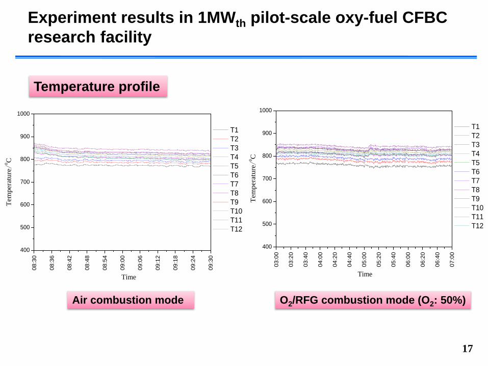
Experiment results in 1MWth pilot-scale oxy-fuel CFBC research facility
17
Air combustion mode O2/RFG combustion mode (O2: 50%)
Temperature profile
08:3
0
08:3
6
08:4
2
08:4
8
08:5
4
09:0
0
09:0
6
09:1
2
09:1
8
09:2
4
09:3
0
400
500
600
700
800
900
1000
Te
mpe
ratu
re/
0 C
Time
T1 T2 T3 T4 T5 T6 T7 T8 T9 T10 T11 T12
03:0
0
03:2
0
03:4
0
04:0
0
04:2
0
04:4
0
05:0
0
05:2
0
05:4
0
06:0
0
06:2
0
06:4
0
07:0
0
400
500
600
700
800
900
1000
Te
mpe
ratu
re/
0 C
Time
T1 T2 T3 T4 T5 T6 T7 T8 T9 T10 T11 T12
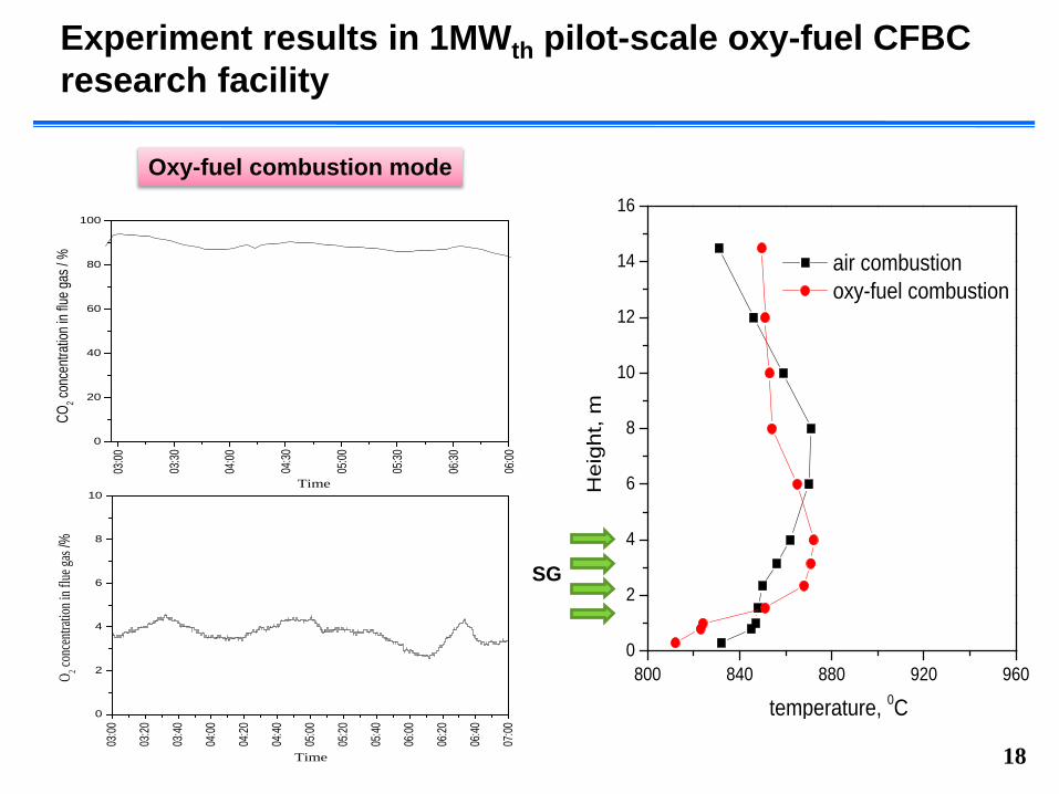
Experiment results in 1MWth pilot-scale oxy-fuel CFBC research facility
18
Oxy-fuel combustion mode
800 840 880 920 9600
2
4
6
8
10
12
14
16
Hei
ght,
m
temperature, 0C
air combustion oxy-fuel combustion
SG
0
20
40
60
80
100
06:00
06:30
05:30
05:00
04:30
04:00
03:30
Time
CO2 co
ncen
tratio
n in f
lue ga
s / %
03:00
03:00
03:20
03:40
04:00
04:20
04:40
05:00
05:20
05:40
06:00
06:20
06:40
07:00
0
2
4
6
8
10
O 2 co
ncen
tratio
n in f
lue ga
s /%
Time
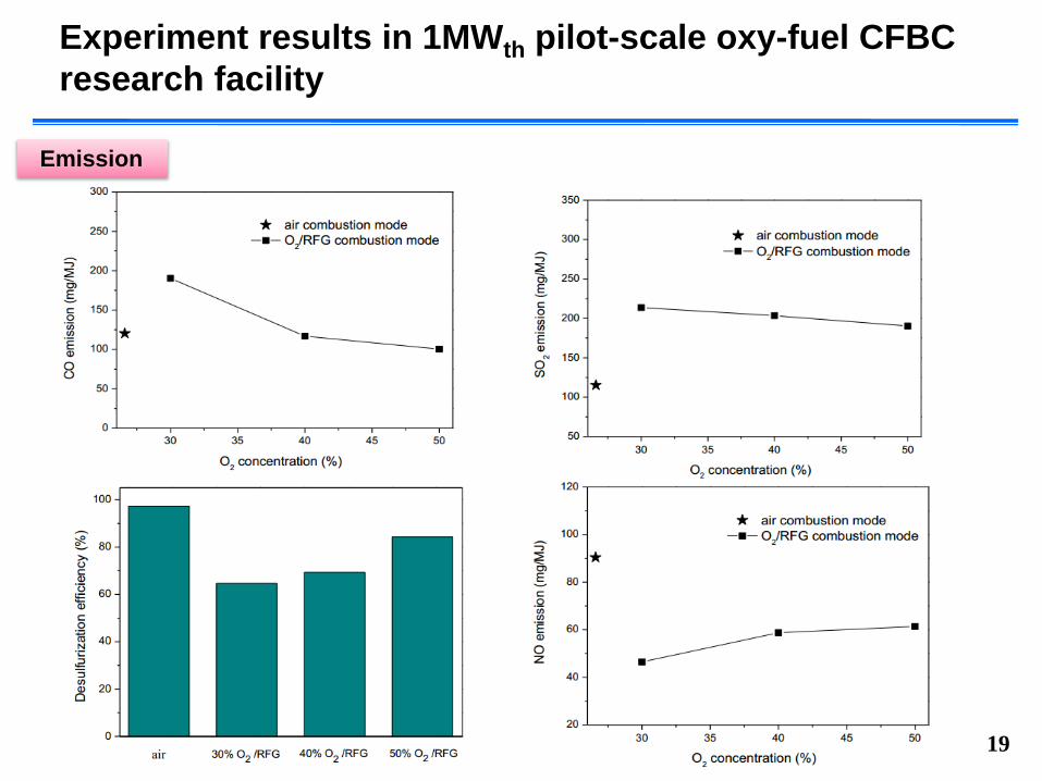
Experiment results in 1MWth pilot-scale oxy-fuel CFBC research facility
19
Emission
Conclusion and Future Work
Oxy-fuel combustion experiments employing high oxygen concentrations with dry flue gas recirculation were successfully carried out in a 1MWth pilot-scale oxy-fuel CFBC unit at the IET/CAS.
This test facility can be operated at air and total oxygen concentrations in the range of 21−50% with different oxygen level in primary and secondary gas.
The results show that the operation of oxy-fuel CFBC at high overall O2 concentration was stable and reliable, and is able to produce flue gas highly concentrated in CO2. The transition from air combustion to oxy-fuel combustion occurs easily and smoothly.
Under 50% O2/RFG combustion mode, with external heat exchanger and water cooling tubes to cool the return solids, the recirculation flue gas ratio is much lower compared to pulverized coal oxy-fuel units.
20
Conclusion and Future Work
Under 50% O2/RFG combustion mode, gaseous pollutant emissions for CO and NO are lower than those in air combustion. SO2 concentration significantly increases with levels up to three times higher compared to air combustion mode, which may produce considerably higher corrosion concerns.
Future work Adding CPU unit to 1MWth pilot-scale oxy-fuel CFBC in 2015 Research of the effect of operation parameters under O2/RFG with
high oxygen concentration (~50%) on combustion characteristic and emission Oxygen concentration level Oxygen staging Combustion temperature Ca/S Fuel
Biomass Oxy-fuel CFB combustion21