design and analysis of hydraulically driven actuation
TRANSCRIPT

Design and Analysis of Hydraulically Driven Actuation SystemFor a Parabolic Solar Trough
by
Katarina Popovic
Submitted to theDepartment of Mechanical Engineering
in Partial Fulfillment of the Requirements for the Degree of
Bachelor of Science in Mechanical Engineering
at the
Massachusetts Institute of Technology
June 2013
ARCHIVMd~ zk~db TS NSTITUTE
C OF CNQLOCYY
JUL 3 1 2013
LIBRARIES
© 2013 Massachusetts Institute of Technology. All rights reserved.
Signature of Author:,bepartmlent of Mechanical Engineering
May 21, 2013
Certified by:Alexander H. Slocum
Pappalardo Professor of Mechanical EngineeringThesis Supervisor
Accepted by:Anette Hosoi
Professor of Mechanical EngineeringUndergraduate Officer
1


Design and Analysis of Hydraulically Driven Actuation SystemFor a Parabolic Solar Trough
by
Katarina Popovic
Submitted to the Department of Mechanical Engineeringon May 21, 2013 in Partial Fulfillment of the
Requirements for the Degree of
Bachelor of Science in Mechanical Engineering
3
Abstract
This thesis documents Katarina Popovic's contribution to the design of hydraulic cylinder
actuation system for day to day solar trough sun tracking, a semester long project within 2.752
Development of Mechanical Products class. The primary goal of this project was to design a
robust mechanical system while reducing the complexity and thus overall cost of the solar trough
assembly for the production line. The mechanism suggested in this thesis actuates both sides of
the solar trough simultaneously, as well as exploit hydraulic cylinder's full range stroke in order
to deliver ±1100 rotational requirement. The rotational motion is achieved through a pulley and a
wire rope system, actuated by a single, double action double rod cylinder. As this project funding
was received from our sole sponsor, an Italian multinational energy company, during the design
process the ultimate goal of eventual production line was kept in mind. However slight design
modifications have been made in order to install and test the actuation system on the already
existing 4m solar trough prototype on site in Pittsfield, New Hampshire.
Thesis Supervisor: Alexander H. SlocumTile: Pappalardo Professor of Mechanical Engineering
4

Acknowledgments
First of all I would like to thank Professor Alex Slocum for all the knowledge that he has
open-handedly shared over the course of the last year. I am very fortunate to have you as my
mentor both in and out of the classroom. I would also like to thank Sandy Campbell for his
enthusiasm and guidance, as well as valuable design reviews throughout this project. Secondly I
would like to thank my teammates, Aaron Flores and Felipe Carillo for their collaboration during
the course of the semester. This project has been a great learning experience that would not be
possible without your help. Lastly, but not least, to a fellow particle, Folkers E. Rojas: thank you
for sharing you zealot enthusiasm for analysis as well as for all the help with formatting of this
thesis.
5
Table of ContentsA b stract ........................................................................................................................................... 4Acknowledgm ents ........................................................................................................................... 5List of Figures ................................................................................................................................. 81. Introduction ........................................................................................................................... 10
1. 1. M otivation ..................................................................................................................... 101.2. Goals ............................................................................................................................. 111.3. Functional Requirem ents .............................................................................................. 11
2. Existing Prototype ................................................................................................................. 132.1. Background ................................................................................................................... 132.2. Solar Trough Structure .................................................................................................. 132.3. Actuation System .......................................................................................................... 14
2.4. Loading Analysis .......................................................................................................... 15
2.4.1. W ind Shear Loads ...................................................................................................................... 15
2.4.2. Torque Calculations .................................................................................................................. 16
3. Strategies ............................................................................................................................... 18
3.1. Transm ission Ratio ....................................................................................................... 19
3.1.1. Hydraulic Cylinder Placem ent ............................................................................................... 20
3.1.2. Transm ission Ratio Optim ization ........................................................................................ 20
3.2. Double Cylinder ............................................................................................................ 22
3.3. Single Cylinder ............................................................................................................. 23
3.4. Strategy Evaluation ....................................................................................................... 24
4. Perform ance & Cost Comparison .......................................................................................... 24
5. Proof of Concept Prototype ................................................................................................... 25
5.1. Design ........................................................................................................................... 26
5.2. Testing ........................................................................................................................... 27
5.3. Results ........................................................................................................................... 27
6. Full Scale Prototype ............................................................................................................... 27
6.1. Sizing Considerations ................................................................................................... 27
6.1.1. Capstan Pulley ............................................................................................................................. 27
6.1.2. W ire Rope ...................................................................................................................................... 28
6.1.3. W ire Accessories ........................................................................................................................ 29
6.2. Hydraulic Cylinder Specifications and Controls .......................................................... 29
6
6.3. Assem bly ....................................................................................................................... 30
6.4. Expected Results ........................................................................................................... 30
7. Full Scale Prototype ............................................................................................................... 30
7.1. Design Advantages ....................................................................................................... 31
7.2. Cost Com parison ........................................................................................................... 31
8. Conclusion ............................................................................................................................. 32
9. Future W ork ........................................................................................................................... 33
Bibliography ................................................................................................................................. 34
7
List of Figures
Figure 1 Concentrating Solar resources in the US (EIA, Sept. 2012) ....................................... 10Figure 2: Existing H ardw are...................................................................................................... 13Figure 3: Existing 4 m solar trough actuation system............................................................... 14Figure 4: Wind Shear Power Law Prediction ............................................................................. 15Figure 5: Solar Trough D im ensions........................................................................................... 16Figure 6: Wind Forces Torque about pivot point as a function of stall angle. .......................... 18Figure 7: Early Concepts: (a) Transmission Ratio (b) Double Cylinder (c) Single Cylinder ...... 19Figure 8: Transmission ratio schematic diagram...................................................................... 19Figure 9: Safety Factor as a function of transmission ratio (TR) and delivered torque (T)......... 21Figure 10: Safety factor contour plot as a function of lever arm radius and transmission ratio... 21Figure 11: Double Cylinder Mounting Configurations. ........................................................... 23Figure 12: Single Cylinder Mounting Configurations............................................................... 24Figure 13: Small Scale Model (a) Double Cylinder Design (b) Single Cylinder Design......... 26Figure 14: Capstan pulley designs (a) grooved lebus (b) flat winch. ....................................... 28Figure 15: Wire rope specifications - function of driving pulley/wire rope diameter ratio..... 29Figure 16: CAD of actuation on 4 m scale prototype. .............................................................. 30Figure 17: Close up of the driving pulley. ................................................................................ 31
8

List of Tables
Table 1 Strategy evaluation based on the functional requirements .......................................... 24Table 2: Small Scale Cost Comparison ................................................................................... 25Table 3: Full Scale Cost Comparison ........................................................................................ 32
9

1. IntroductionAs the price of oil increases renewable energy becomes more lucrative. In the U.S.,
renewable energy makes about 9% of the total energy produced. Currently, solar and PV energy
sources makes up about 2% of the total renewable energy. Therefore, solar trough fields
collecting solar energy that is fed into the national grid system makes up less than a one quarter
of a percent of the total green energy used in the U.S. One of the main driving costs these
systems encounter is the actuation and controls. This research seeks to develop a cost effective
prototype actuation system for a solar trough. The research presented in this thesis was
developed as part of a mechanical product development senior design course.
1.1. MotivationThe solar energy delivered to states west of the Mississippi River is on average 5kWh/m 2
per day, as shown in Figure 1 (EIA, Sept. 2012). Due to the efficiencies in solar collection
technology the maximum energy expected from a standard unit is estimated about 1 kW/m2 . As
stated by the National Research Energy Laboratory, the main cost reduction of solar concentrator
technology will depend largely on: size scale up, production volume, and increased competition
(NREL, Oct. 2003). Therefore, a robust and economical actuation system designed for
scalability for the solar trough industry is one means to reduce cost and improve the proliferation
of solar troughs.
13 NR E L
Figure 1 Concentrating Solar resources in the US (EIA, Sept. 2012)
10

Parabolic trough is a type of solar thermal collector that works by focusing sun rays onto
a tube with circulating heat transfer fluid it represents an active energy converting system. The
efficiency of the solar trough is dependent on many variables some of which are trough structural
design, material selection, and wear (Figueredo, 2011). Energy efficiency of solar trough is also
affected by the losses due to the structural support shadow casting while the Sun is on the
northern side. As such, it is also important to design compact actuating systems to decrease the
shading losses (O'Rourke, 2011).
1.2. GoalsThe objective of this project is to design, evaluate and prototype a cost effective parabolic
solar trough actuation system that will address flaws within the existing actuation system
(O'Rourke, 2011). The design must take into account the environmental loading which includes
hot dessert climate with heavy winds during desert storms. Some of design specifications are
provided by Ente Nazionale Idrocarburi (ENI), an Italian multinational company, which is a key
driving force behind this energy initiative project.
1.3. Functional RequirementsSeveral of the requirements were provided for the environmental conditions at the
installation site. Other functional requirements are set to minimize cost, and complexity while at
the same time ensuring that the design functions with the existing structure of solar troughs being
developed by ENI as well as the respective scaled model installed at the New Hampshire site.
(1) Torque Rating
Torque requirement is necessary in order to ensure that the trough actuation
system can support the solar trough at desired angle even at the harshest weather
conditions. The collaboration with another group of ENI at the Polytechnic Institute
of Milano determined the maximum torque based on the structural strength of the
trough. Their analysis concluded that the actuation system needs to support a
maximum torque of 1500 Nm, occurring at an 800 stall angle.
(2) Rotational Range
Unlike conventional solar troughs, the rotational angle of the system has to be at
least 2200 (i.e. ± 1100 from the mid plane). The extended range of motion is required
for safety and storage purposes. During desert storms the solar troughs can
11
experience wind loads above the design specifications. One of the options is to size
the entire unit to withstand the foreseeable maximum loads; however, the cost of that
unit would increase dramatically. As such, the rotational freedom of 1100 in both
clock wise and counter clock wise directions is needed to store and protect the solar
trough in case of adverse environmental conditions.
(3) Actuation
The existing solar trough prototype has a low torsional rigidity. Actuating solar
trough from only one side will increase deflection at the center of the structure by
approximately sixteen times (O'Rourke, 2011). Over time cycling the trough thru
those deflections can lead to failure in the components. Therefore, the actuation
system proposed must be mirrored on both sides of the solar trough to minimize
structural deflections. Looking ahead towards serial in line positioning of the troughs
while sharing the actuation system between two different structures is an additional
incentive for this requirement fulfillment.
(4) Complexity
Since complexity is usually analogous to cost, minimizing complexity of the
actuation system is crucial. One limitation of the existing system is the complex
controller due to the multiple cylinders used for actuation of the trough that has
further to do with the nature of mechanical design of the actuating system.
(5) Cost
Cost equals profit. Therefore, the cost of operation and parts must be comparable
to existing technologies if not cheaper.
(6) Interface
The proposed drive system must be designed to interface with the existing 4 m
solar trough prototype. This further comes down to actuating the trough at about its
center of gravity point.
12
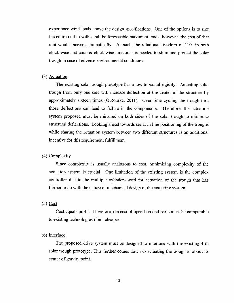
2. Existing PrototypeThe proposed actuation system will interface with the already existing 4 m solar trough,
Figure 2, located in Pittsfield, New Hampshire.
Figure 2: Existing Hardware
2.1. BackgroundThe solar trough was built in the spring semester of 2011 as part of the 2.752 coursework
and later as a research in the Precision Engineering Group. An actuation system was
incorporated on the solar trough with a dual piston system, shown in Figure 3. However, the
control method of the actuation is unreliable and the method adds loads on the shaft that cause it
to undergo unfavorable torsion. Since the original installation very little development has been
done on the unit.
2.2. Solar Trough StructureSolar trough itself consists of rolled steel plates coated with a reflective film. This novel
design replaced glass panels but at a fraction of the cost (Figueredo, 2011). On each end these
panels are supported by a bulkhead that contains steel end tee shaped plate to which existing
actuating system attaches to. Due to its size and the need for full 1100 rotation in both directions,
the solar collector structure is lifted by four cement blocks to a desired height.
13
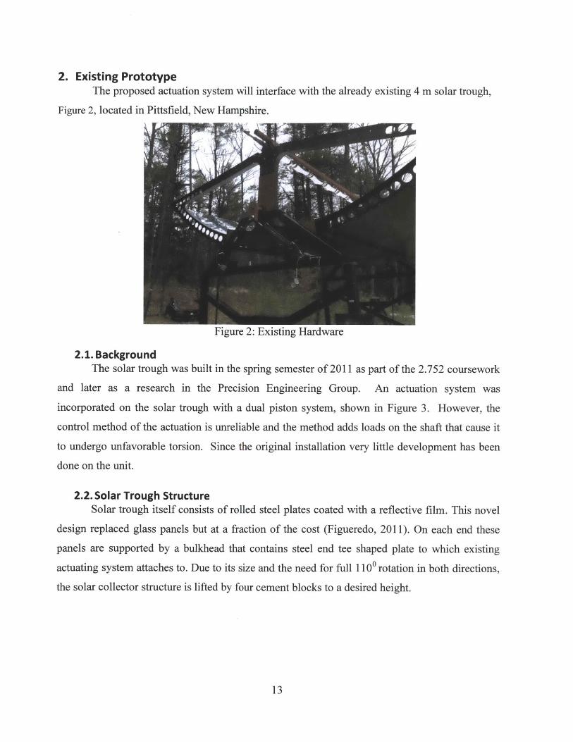
2.3. Actuation SystemThe system currently installed in New Hampshire uses a lever arm design, Figure 3
Figure 3: Existing 4 m solar trough actuation system
It employs two inch bore single action single rod hydraulic cylinders with a stroke length
of eighteen inches that apply force to the crank plate creating necessary torque for trough
rotation. The crank is further connected to the shaft that passes through the troughs' center of
gravity. Cylinders are actuated one at the time such that while right cylinder is engaged, and the
left one is floating, the trough rotates clockwise, and vice versa. While it cannot be seen from
the picture, same actuation system is mirrored and installed on the other side of the solar trough
such that at each rotation there are two cylinders powering the rotational motion in each
direction.
Although the existing hardware satisfies functional requirements set by ENI, there is
room for improvement. The geometric constraint such as angular cylinder mounting does not
allow fully exploitation of hydraulic force. As it can be seen from the above cylinders are
mounted at an angle. As such, hydraulic force exerted onto the lever arm creates angle of 900
only once throughout the trough's 1100 sweep thus applying maximum torque for a very brief
point in time. Also the mounting point of the lever arm located at the end of the shaft coupled
with the excessive hydraulic force and single shear effect results in visible shaft deflections
during actuation of the system. Second of all, the system of two cylinders per side not only
complicates the control scheme of consecutive actuation but due to the design constrains, it is
14
necessary. In the current configuration, each of the cylinders goes through zero point motion
once during their float time. Aligning with the lever arm on their retraction portion and thus
applying no torque onto the lever arm is the reason behind using two single action cylinders in
engaged/float combination instead of one constantly engaged dual action cylinder.
2.4. Loading AnalysisIn the initial stage of this project, our group did first order calculations of torque
requirements due to the wind loading. As such, the initial step was to determine the loads felt on
the trough as a consequence of wind effects.
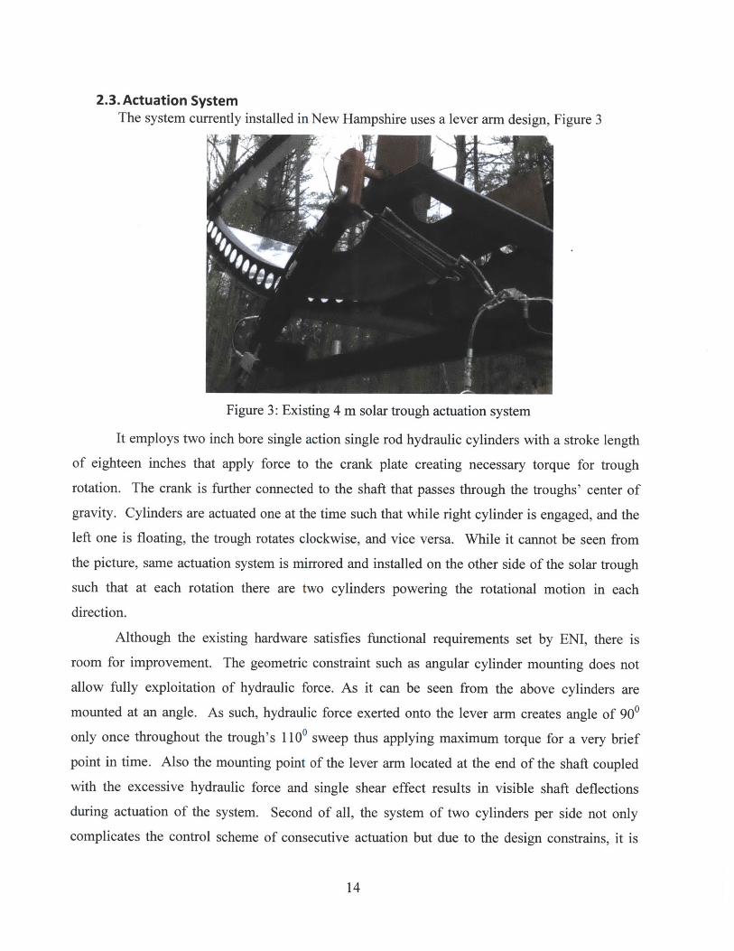
2.4.1. Wind Shear LoadsThe wind velocity was modeled using wind shear power law with shear exponent of 1
and predicted reference speed of wind Vref =15 m/s at the height of href = 7 m. Equation 1 shows
the relation between the wind strength and the respective chosen height.
Vwind (h) =ref (href) ( ) Equation 1
The linear behavior can be represented graphically as shown in Figure 4.
2 4 6 8Height (m)
10 12 14
Figure 4: Wind Shear Power Law Prediction
15
Wind Shear Power LawTrendline: VwInd = 2.143z
7
6
5
4
3
E0
Ca
00
Justification behind high shear exponent value is the nature of solar trough positioning in
a matrix configuration and as such creating obstructions to the neighboring systems, as well as
relatively short height of the structure.
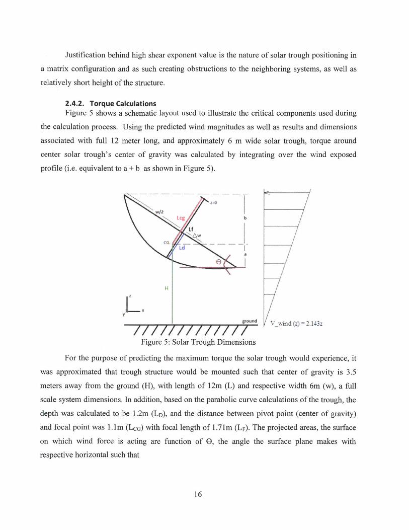
2.4.2. Torque CalculationsFigure 5 shows a schematic layout used to illustrate the critical components used during
the calculation process. Using the predicted wind magnitudes as well as results and dimensions
associated with full 12 meter long, and approximately 6 m wide solar trough, torque around
center solar trough's center of gravity was calculated by integrating over the wind exposed
profile (i.e. equivalent to a + b as shown in Figure 5).
Lcg b
Lf
/wind (z)=2.143z
Figure 5: Solar Trough Dimensions
For the purpose of predicting the maximum torque the solar trough would experience, it
was approximated that trough structure would be mounted such that center of gravity is 3.5
meters away from the ground (H), with length of 1 2m (L) and respective width 6m (w), a full
scale system dimensions. In addition, based on the parabolic curve calculations of the trough, the
depth was calculated to be 1 .2m (LD), and the distance between pivot point (center of gravity)
and focal point was 1. im (LcG) with focal length of 1 .71m (LF). The projected areas, the surface
on which wind force is acting are function of 0, the angle the surface plane makes with
respective horizontal such that
16

Wa = - Aw)- sin
(Wb = (12+w -Wsin 0
Equation 2
The net torque about the center of rotation of the trough is found by adding positive
moment experienced by surface a and positive moment as result of lower surface area b such that
T net = (Zb - H)Fb - (H - Za)F Equation 3
Where Za and zb are respectively centroid of the net force applied on the upper and lower
portion of the trough such that
0.5 - PCd L 1H-a Vwin- z 2 dZ
a 0.5 -pcdL fH-a Z2dZ
H+b0.5 = .pcdL f, Vwind dz
Zb 05H+b I dz0.5 - pca LfH r 2
Equation 4
Equation 5
Respective upper and lower drag forces were calculated by integrating assumed linear
wind profile previously calculated across the trough surface contour and are as such
HFa = 5PCdL fH
Fb = . 5 pCd L JH~
Vwind z 2 dz
Vwind -z 2 dz
Where p is air's density, cd is the coefficient of drag, and Vwind is the trend line fitted to
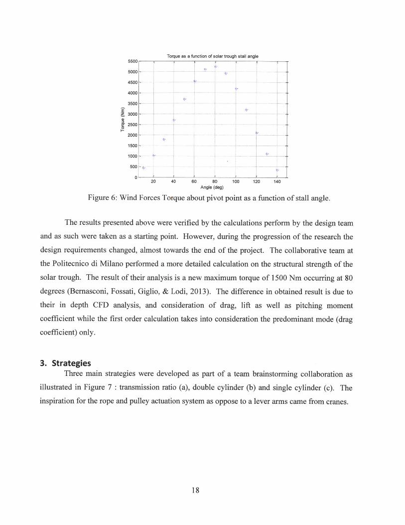
the wind power shear law previously calculated. As a result of these calculations it was found
that the maximum torque happens at around 800 and it is on the order of 5000 Nm.
17
Equation 6
Torque as a function of solar trough stall angle5500
5000 -
4500
4000
3500 -
z 3000
22500 -0
2000 -
1500-
1000 .
500
020 40 60 80 100 120 140
Angle (deg)
Figure 6: Wind Forces Torque about pivot point as a function of stall angle.
The results presented above were verified by the calculations perform by the design team
and as such were taken as a starting point. However, during the progression of the research the
design requirements changed, almost towards the end of the project. The collaborative team at
the Politecnico di Milano performed a more detailed calculation on the structural strength of the
solar trough. The result of their analysis is a new maximum torque of 1500 Nm occurring at 80
degrees (Bernasconi, Fossati, Giglio, & Lodi, 2013). The difference in obtained result is due to
their in depth CFD analysis, and consideration of drag, lift as well as pitching moment
coefficient while the first order calculation takes into consideration the predominant mode (drag
coefficient) only.
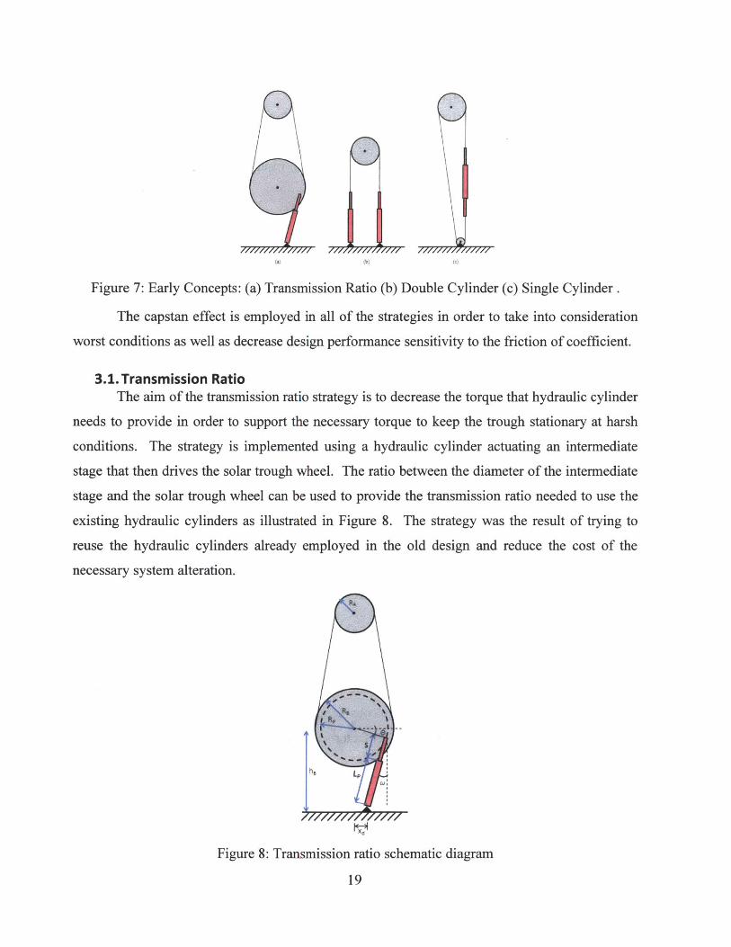
3. StrategiesThree main strategies were developed as part of a team brainstorming collaboration as
illustrated in Figure 7 : transmission ratio (a), double cylinder (b) and single cylinder (c). The
inspiration for the rope and pulley actuation system as oppose to a lever arms came from cranes.
18
(b|
Figure 7: Early Concepts: (a) Transmission Ratio (b) Double Cylinder (c) Single Cylinder.
The capstan effect is employed in all of the strategies in order to take into consideration
worst conditions as well as decrease design performance sensitivity to the friction of coefficient.
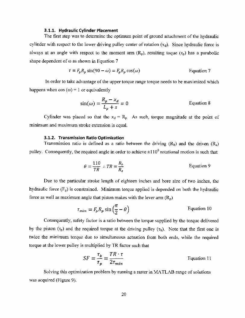
3.1. Transmission RatioThe aim of the transmission ratio strategy is to decrease the torque that hydraulic cylinder
needs to provide in order to support the necessary torque to keep the trough stationary at harsh
conditions. The strategy is implemented using a hydraulic cylinder actuating an intermediate
stage that then drives the solar trough wheel. The ratio between the diameter of the intermediate
stage and the solar trough wheel can be used to provide the transmission ratio needed to use the
existing hydraulic cylinders as illustrated in Figure 8. The strategy was the result of trying to
reuse the hydraulic cylinders already employed in the old design and reduce the cost of the
necessary system alteration.
Figure 8: Transmission ratio schematic diagram
19
3.1.1. Hydraulic Cylinder PlacementThe first step was to determine the optimum point of ground attachment of the hydraulic
cylinder with respect to the lower driving pulley center of rotation (Xd). Since hydraulic force is
always at an angle with respect to the moment arm (Rp), resulting toque (Tp) has a parabolic
shape dependent of o as shown in Equation 7
T = FR sin(90 - w) = FR, cos(o) Equation 7
In order to take advantage of the upper torque range torque needs to be maximized which
happens when cos (o)= 1 or equivalently
sin( R) = R ' = 0 Equation 8LP + S
Cylinder was placed so that the Xd = Rp. As such, torque magnitude at the point of
minimum and maximum stroke extension is equal.
3.1.2. Transmission Ratio OptimizationTransmission ratio is defined as a ratio between the driving (Rb) and the driven (Ra)
pulley. Consequently, the required angle in order to achieve ± 1100 rotational motion is such that
110 _Rb
0 = --- TR = - Equation 9TR Ra
Due to the particular stroke length of eighteen inches and bore size of two inches, the
hydraulic force (Fp) is constrained. Minimum torque applied is depended on both the hydraulic
force as well as maximum angle that piston makes with the lever arm (RP)
T = FR sin ( - 0) Equation 10
Consequently, safety factor is a ratio between the torque supplied by the torque delivered
by the piston (Tp) and the required torque at the driving pulley (Tb). Note that the first one is
twice the minimum torque due to simultaneous actuation from both ends, while the required
torque at the lower pulley is multiplied by TR factor such that
Tb TR-rSF - - - -Equation 11
Tp 2 Tmin
Solving this optimization problem by running a raster in MATLAB range of solutions
was acquired (Figure 9).
20
15
(U
U)
-0.50.
3 0.4 5
2 0.2 0.3Transamition Rafto (#)A 0.1
R (m)
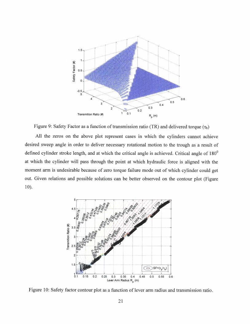
Figure 9: Safety Factor as a function of transmission ratio (TR) and delivered torque (-b)
All the zeros on the above plot represent cases in which the cylinders cannot achieve
desired sweep angle in order to deliver necessary rotational motion to the trough as a result of
defined cylinder stroke length, and at which the critical angle is achieved. Critical angle of 1800
at which the cylinder will pass through the point at which hydraulic force is aligned with the
moment arm is undesirable because of zero torque failure mode out of which cylinder could get
out. Given relations and possible solutions can be better observed on the contour plot (Figure
10).
5
4.5
3.5
3
2.5
2
1.5
0.1 0.15 0.2 0.25 0.3 0.35Lever Arm Radius
0.4 0.45 0.5 0.55 0.6R (M)
Figure 10: Safety factor contour plot as a function of lever arm radius and transmission ratio.
21
0
Ea
ev'S
0)~ ~Q.
CVIQ).-
4(5'45
'4 ( 5 )SF(Pr
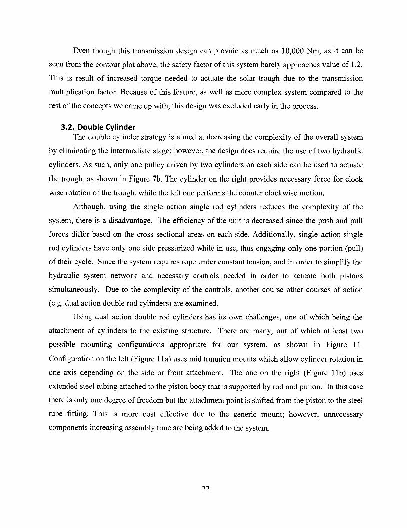
Even though this transmission design can provide as much as 10,000 Nm, as it can be
seen from the contour plot above, the safety factor of this system barely approaches value of 1.2.
This is result of increased torque needed to actuate the solar trough due to the transmission
multiplication factor. Because of this feature, as well as more complex system compared to the
rest of the concepts we came up with, this design was excluded early in the process.
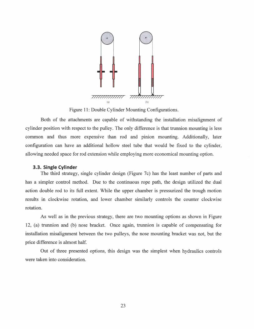
3.2. Double CylinderThe double cylinder strategy is aimed at decreasing the complexity of the overall system
by eliminating the intermediate stage; however, the design does require the use of two hydraulic
cylinders. As such, only one pulley driven by two cylinders on each side can be used to actuate
the trough, as shown in Figure 7b. The cylinder on the right provides necessary force for clock
wise rotation of the trough, while the left one performs the counter clockwise motion.
Although, using the single action single rod cylinders reduces the complexity of the
system, there is a disadvantage. The efficiency of the unit is decreased since the push and pull
forces differ based on the cross sectional areas on each side. Additionally, single action single
rod cylinders have only one side pressurized while in use, thus engaging only one portion (pull)
of their cycle. Since the system requires rope under constant tension, and in order to simplify the
hydraulic system network and necessary controls needed in order to actuate both pistons
simultaneously. Due to the complexity of the controls, another course other courses of action
(e.g. dual action double rod cylinders) are examined.
Using dual action double rod cylinders has its own challenges, one of which being the
attachment of cylinders to the existing structure. There are many, out of which at least two
possible mounting configurations appropriate for our system, as shown in Figure 11.
Configuration on the left (Figure 1 Ia) uses mid trunnion mounts which allow cylinder rotation in
one axis depending on the side or front attachment. The one on the right (Figure 1 b) uses
extended steel tubing attached to the piston body that is supported by rod and pinion. In this case
there is only one degree of freedom but the attachment point is shifted from the piston to the steel
tube fitting. This is more cost effective due to the generic mount; however, unnecessary
components increasing assembly time are being added to the system.
22
(a) (b)
Figure 11: Double Cylinder Mounting Configurations.
Both of the attachments are capable of withstanding the installation misalignment of
cylinder position with respect to the pulley. The only difference is that trunnion mounting is less
common and thus more expensive than rod and pinion mounting. Additionally, later
configuration can have an additional hollow steel tube that would be fixed to the cylinder,
allowing needed space for rod extension while employing more economical mounting option.
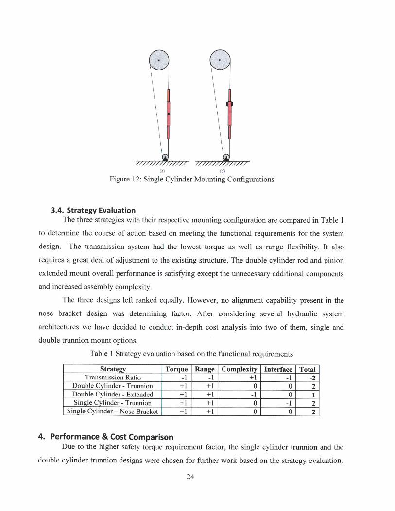
3.3. Single CylinderThe third strategy, single cylinder design (Figure 7c) has the least number of parts and
has a simpler control method. Due to the continuous rope path, the design utilized the dual
action double rod to its full extent. While the upper chamber is pressurized the trough motion
results in clockwise rotation, and lower chamber similarly controls the counter clockwise
rotation.
As well as in the previous strategy, there are two mounting options as shown in Figure
12, (a) trunnion and (b) nose bracket. Once again, trunnion is capable of compensating for
installation misalignment between the two pulleys, the nose mounting bracket was not, but the
price difference is almost half.
Out of three presented options, this design was the simplest when hydraulics controls
were taken into consideration.
23
(a) (b)
Figure 12: Single Cylinder Mounting Configurations
3.4. Strategy EvaluationThe three strategies with their respective mounting configuration are compared in Table 1
to determine the course of action based on meeting the functional requirements for the system
design. The transmission system had the lowest torque as well as range flexibility. It also
requires a great deal of adjustment to the existing structure. The double cylinder rod and pinion
extended mount overall performance is satisfying except the unnecessary additional components
and increased assembly complexity.
The three designs left ranked equally. However, no alignment capability present in the
nose bracket design was determining factor. After considering several hydraulic system
architectures we have decided to conduct in-depth cost analysis into two of them, single and
double trunnion mount options.
Table 1 Strategy evaluation based on the functional requirements
Strategy Torque Range Complexity Interface TotalTransmission Ratio -1 -1 +1 -1 -2
Double Cylinder - Trunnion +1 +1 0 0 2Double Cylinder - Extended +1 +1 -1 0 1Single Cylinder - Trunnion +1 +1 0 -1 2
Single Cylinder - Nose Bracket +1 +1 0 0 2
4. Performance & Cost ComparisonDue to the higher safety torque requirement factor, the single cylinder trunnion and the
double cylinder trunnion designs were chosen for further work based on the strategy evaluation.
24

A more detailed cost estimate of the two strategies is shown in Table 2. The most expensive unit
of both designs is dual action double rod hydraulic actuators and the respective trunnion
brackets. However, the double cylinder has two of each while the single has only one. This at the
first look minor difference increases the overall cost of the system significantly. This difference
multiplies as the system scales up.
Table 2: Small Scale Cost Comparison
Single Cylinder Design Double Cylinder Design
Part QTY unit price total cost QTY unit price total cost
Capstan pulley 1 $ 50.00 $ 50.00 1 $ 50.00 $ 50.00
Idler pulley 1 $ 10.00 $ 10.00 0 $ 0.00 $ 0.00
nuts/anchors 1 $ 10.00 $ 10.00 1 $ 10.00 $ 10.00
wire rope 4.7 $ 0.87 $ 4.09 11 $ 0.87 $ 9.57
Turnbuckle 1 $ 16.37 $ 16.37 1 $ 16.37 $ 16.37
compression sleeves 1 $ 9.31 $ 9.31 1 $ 9.31 $ 9.31
4way valve 1 $ 133.00 $ 133.00 1 $ 133.00 $ 133.00
pneumatic cylinders 1 $ 89.49 $ 89.49 2 $ 89.49 $ 178.98
piston rod clevis 4 $ 6.28 $ 25.12 4 $ 6.28 $ 25.12
Nose mount bracket 2 $ 3.87 $ 7.74 2 $ 3.87 $ 7.74
Speed Muffler 2 $ 3.56 $ 7.12 2 $ 3.56 $ 7.12
1/4" tube fitting 3 $ 1.84 $ 5.52 3 $ 1.84 $ 5.52
1/4" T fitting 2 $ 3.89 $ 7.78 2 $ 3.89 $ 7.78
1/8" tube fitting 3 $ 1.87 $ 5.61 3 $ 1.87 $ 5.61
Polyethylene tubing 1 $ 13.29 $ 13.29 1 $ 13.29 $ 13.29
$ 394.44 $ 479.41
While the single cylinder design is the more cost effective option both units are
comparable in price, due to the very similar components list, as well as overall actuating
mechanism. The team chose to have both prototypes built in order to put them under
performance evaluation testing to determine the future course of action.
5. Proof of Concept PrototypeUsing the fiber glass solar trough that was part of Precision Engineering Research Group
(Figueredo, 2011), our group has installed double cylinder design on one and single cylinder
design on the other end of the structural support as shown in Figure 13. The main purpose behind
25
Grand Total
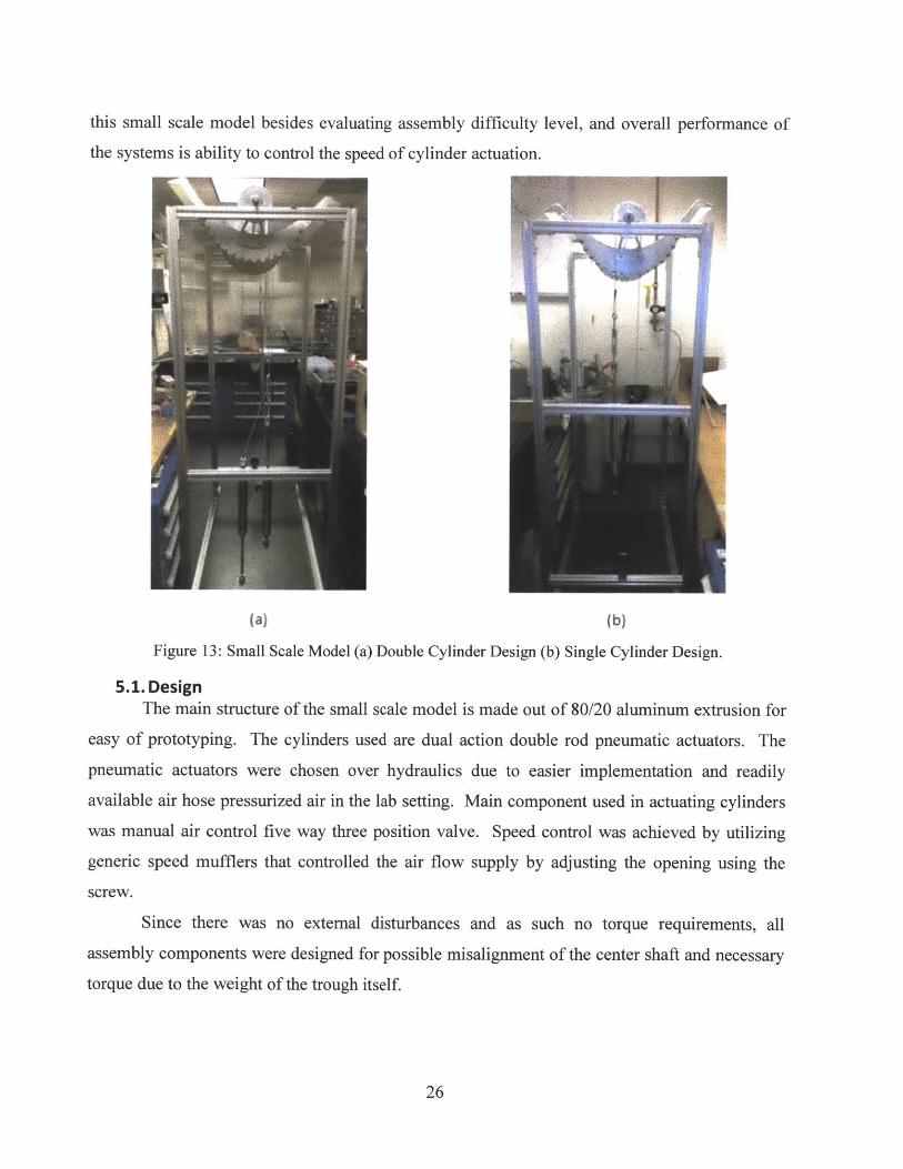
this small scale model besides evaluating assembly difficulty level, and overall performance of
the systems is ability to control the speed of cylinder actuation.
(a) (b)
Figure 13: Small Scale Model (a) Double Cylinder Design (b) Single Cylinder Design.
5.1. DesignThe main structure of the small scale model is made out of 80/20 aluminum extrusion for
easy of prototyping. The cylinders used are dual action double rod pneumatic actuators. The
pneumatic actuators were chosen over hydraulics due to easier implementation and readily
available air hose pressurized air in the lab setting. Main component used in actuating cylinders
was manual air control five way three position valve. Speed control was achieved by utilizing
generic speed mufflers that controlled the air flow supply by adjusting the opening using the
screw.
Since there was no external disturbances and as such no torque requirements, all
assembly components were designed for possible misalignment of the center shaft and necessary
torque due to the weight of the trough itself.
26
5.2. TestingBoth designs were tested independently of each other. The opposite sides of trough had
all the components permanently installed and were controlled by separate valves and speed
muffler pairs. While the pressure rating did not matter in this stage of testing, all the tests were
run at about 80 psi pressure. However, designs were sensitive to the air flow intake; different
performance results were recorded at different flow intakes.
5.3. ResultsDouble cylinder design has proven to be quite complex when assembly took place.
Placement of the cylinders at the exact stroke length with respect to the trough angular position
was rather tedious process. In addition, simultaneous actuation of the cylinders happened only at
the high enough air flow intake. The speedy extension and retraction of the pistons caused slack
in the wire rope and thus slippage at the pulley, the exact effect that we are trying to control.
On opposite end, single cylinder design is less difficult to set up and almost self-aligning.
Also, because of the single cylinder, the control was not a problem and the desired actuation
speed was achieved. As a result, the wire rope was taught all the time and there is no slippage
present. The trough consistently achieved same angular position even after extended period of
actuation.
6. Full Scale PrototypeBased on the results from the small scale testing, together with the cost benefits, the
single cylinder design is the best strategy to implement it in a full scale model.
6.1. Sizing ConsiderationsOur actuation design was divided in three main sections: pulley, wire rope and
accessories, hydraulic actuators, and respective controls.
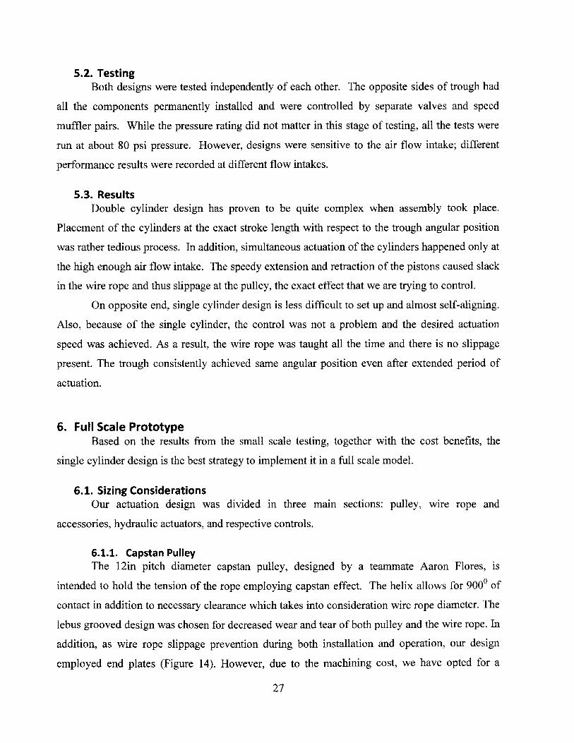
6.1.1. Capstan PulleyThe 12in pitch diameter capstan pulley, designed by a teammate Aaron Flores, is
intended to hold the tension of the rope employing capstan effect. The helix allows for 9000 of
contact in addition to necessary clearance which takes into consideration wire rope diameter. The
lebus grooved design was chosen for decreased wear and tear of both pulley and the wire rope. In
addition, as wire rope slippage prevention during both installation and operation, our design
employed end plates (Figure 14). However, due to the machining cost, we have opted for a
27
simplified pulley design, consisting of circular tubing and without he grooves. Lastly, the pulley
is bolted to a tee shaped plate with six grade 5 SAE hin bolts in circular 8in diameter pattern.
This method gives safety factor of four and was based on the mounting space availability and the
torque requirements.
(a) (b)
Figure 14: Capstan pulley designs (a) grooved lebus (b) flat winch.
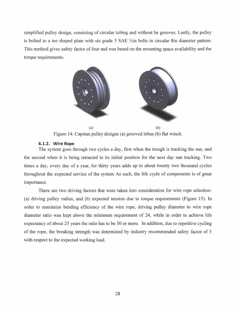
6.1.2. Wire RopeThe system goes through two cycles a day, first when the trough is tracking the sun, and
the second when it is being retracted to its initial position for the next day sun tracking. Two
times a day, every day of a year, for thirty years adds up to about twenty two thousand cycles
throughout the expected service of the system As such, the life cycle of components is of great
importance.
There are two driving factors that were taken into consideration for wire rope selection:
(a) driving pulley radius, and (b) expected tension due to torque requirements (Figure 15). In
order to maximize bending efficiency of the wire rope, driving pulley diameter to wire rope
diameter ratio was kept above the minimum requirement of 24, while in order to achieve life
expectancy of about 25 years the ratio has to be 30 or more. In addition, due to repetitive cycling
of the rope, the breaking strength was determined by industry recommended safety factor of 5
with respect to the expected working load.
28
Service Life100
.2
50
60
70
so
90
Bending Efficiency
-~Vf~~~fIffz90
cc
cc
so
70
2 6 10 14 18 22 26 30 34 38Dd Ratio 10
10 20 30 40 SO 60Old Ratto
(a) (b)
Figure 15: Wire rope specifications - function of driving pulley/wire rope diameter ratio(Installation, Operation and Maintenance Recommendation)
The chosen wire rope for a 12in pulley was a 3/8 in diameter 7x19 constructions steel
wire rope, giving a ratio of 30. Besides the importance of diameter ratio driving factors, this
specific construction was chosen due to the availability of strong end grip fittings (discussed in
the following section) designed for lifting that are not as readily available for the generic 8x19
structure usually employed in the pulley systems.
6.1.3. Wire AccessoriesFor wire rope end fittings as well as turnbuckle selection, working load was main
selection guidance. Strong grip end fittings were chosen over a regular compression sleeve
technique because of (1) their ultimate strength capabilities to withstand 100% of wire rope
breaking strength, as well as (2) inspection hole that allows for proper installation result.
Turnbuckles selection is on contrary rated depending on their workload due to already
built in proof load of two and a half, and ultimate load of five safety factors. The high strength
corrosive resistant closed body turnbuckles were chosen due to enclosed threads and protection
of the debris and particle dust.
6.2. Hydraulic Cylinder Specifications and ControlsAs a group we have decided to go with dual action double rod cylinders with trunnion as
a mounting option. Double rod feature decreased the complexity of the controls systems and
necessary valves needed to actuate the system. The trunnion mounting option has been chosen to
29
JrJ- 1f.I
T
- 7I7~ ~60 r - -
20K
compensate for installation misalignment of pulleys giving the cylinder flexibility to align with
the rope. For more details and in depth analysis and selection process for the hydraulic system
and controls used in the final design please refer to my team mate thesis (Carillo, 2013).
6.3. AssemblyThe assembly process should follow similar steps as the small scale model. Components
such as driving pulley, idler pulley, as well as mounting of the hydraulic cylinder and all the
necessary hydraulic connections should take place first. When installing the wire rope and
turnbuckle it is recommended to fully extend the turnbuckle before making all the right
connections. The tensioning would come only after the cylinder is engaged. While that is taking
place, constant eye should be kept on the solar trough alignment with respect to the stroke
extensions.
6.4. Expected ResultsIt is expected that the performance of the full model would not defer much at all if any
from the small scale prototype results. Due to the size of the system, extra precaution should be
however taken when the fine tuning of hydraulic system as well as tensioning of the rope takes
place.
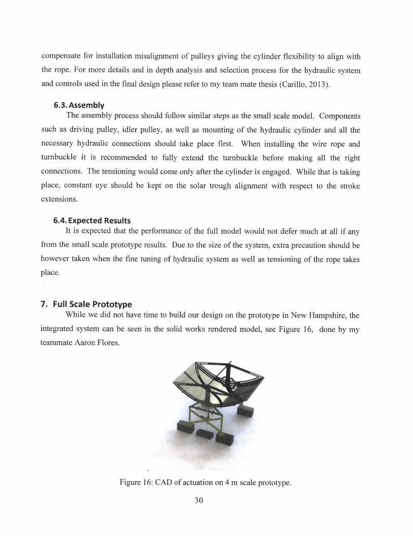
7. Full Scale PrototypeWhile we did not have time to build our design on the prototype in New Hampshire, the
integrated system can be seen in the solid works rendered model, see Figure 16, done by my
teammate Aaron Flores.
Figure 16: CAD of actuation on 4 m scale prototype.
30
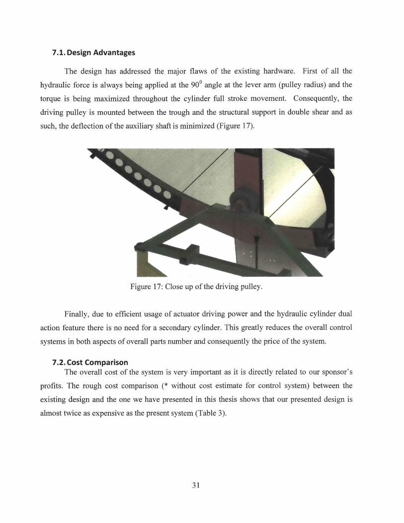
7.1. Design Advantages
The design has addressed the major flaws of the existing hardware. First of all the
hydraulic force is always being applied at the 900 angle at the lever arm (pulley radius) and the
torque is being maximized throughout the cylinder full stroke movement. Consequently, the
driving pulley is mounted between the trough and the structural support in double shear and as
such, the deflection of the auxiliary shaft is minimized (Figure 17).
Figure 17: Close up of the driving pulley.
Finally, due to efficient usage of actuator driving power and the hydraulic cylinder dual
action feature there is no need for a secondary cylinder. This greatly reduces the overall control
systems in both aspects of overall parts number and consequently the price of the system.
7.2. Cost ComparisonThe overall cost of the system is very important as it is directly related to our sponsor's
profits. The rough cost comparison (* without cost estimate for control system) between the
existing design and the one we have presented in this thesis shows that our presented design is
almost twice as expensive as the present system (Table 3).
31
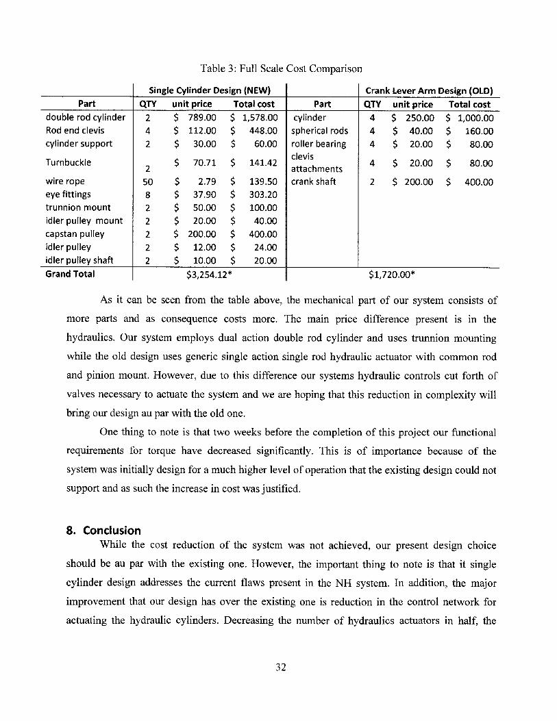
Table 3: Full Scale Cost Comparison
Single Cylinder Design (NEW) Crank Lever Arm Design (OLD)Part QTY unit price Total cost Part QTY unit price Total cost
double rod cylinder 2 $ 789.00 $ 1,578.00 cylinder 4 $ 250.00 $ 1,000.00Rod end clevis 4 $ 112.00 $ 448.00 spherical rods 4 $ 40.00 $ 160.00cylinder support 2 $ 30.00 $ 60.00 roller bearing 4 $ 20.00 $ 80.00
Turnbuckle 2 $ 70.71 $ 141.42 clevis 4 $ 20.00 $ 80.002attachments 4 $200 $ 8.0wire rope 50 $ 2.79 $ 139.50 crank shaft 2 $ 200.00 $ 400.00eye fittings 8 $ 37.90 $ 303.20trunnion mount 2 $ 50.00 $ 100.00idler pulley mount 2 $ 20.00 $ 40.00capstan pulley 2 $ 200.00 $ 400.00idler pulley 2 $ 12.00 $ 24.00idler pulley shaft 2 $ 10.00 $ 20.00
Grand Total $3,254.12* $1,720.00*
As it can be seen from the table above, the mechanical part of our system consists of
more parts and as consequence costs more. The main price difference present is in the
hydraulics. Our system employs dual action double rod cylinder and uses trunnion mounting
while the old design uses generic single action single rod hydraulic actuator with common rod
and pinion mount. However, due to this difference our systems hydraulic controls cut forth of
valves necessary to actuate the system and we are hoping that this reduction in complexity will
bring our design au par with the old one.
One thing to note is that two weeks before the completion of this project our functional
requirements for torque have decreased significantly. This is of importance because of the
system was initially design for a much higher level of operation that the existing design could not
support and as such the increase in cost was justified.
8. ConclusionWhile the cost reduction of the system was not achieved, our present design choice
should be au par with the existing one. However, the important thing to note is that it single
cylinder design addresses the current flaws present in the NH system. In addition, the major
improvement that our design has over the existing one is reduction in the control network for
actuating the hydraulic cylinders. Decreasing the number of hydraulics actuators in half, the
32
overall controls components have been cut in four. By having a minimally complex system, the
overall possibility of failure is decreased within the hydraulic components.
9. Future WorkBesides in depth cost analysis on the hydraulic controls and a possibility of slight
reduction in hydraulic actuators depending on the manufacturer as well as distributor, there are
always improvements that can take place to reduce the cost and increase overall system
performance.
First of all different mounting option should be looked into such as rod and pinion
coupled with the appropriate steel sleeve fitting that would press fit onto the cylinder.
Furthermore, it would be good to revisit the first transmission design option. While this design
has major failure more where there is a zero point motion at which hydraulic force would align
with the lever arm and system would be stalled, addition of safety stop in case of extreme
conditions could be installed. Lastly, due to decrease in torque requirements, an electric motor
might be a viable design to look into.
33
Bibliography
Bernasconi, A., Fossati, M., Giglio, M., & Lodi, M. (2013). ENI Trough - Structural SolutionsAnalysis. Milano: Dipartimento Di Meccanica, Politecnico di Milano.
Carillo, J. F. (2013). Mechanical Development of an Actuation System for a parabolic solartrough. Cambridge: Massachusetts Institute of Technology.
EIA. (Sept. 2012). Annual Energy Review 2011. Washington, DC: US Department of Energy.Figueredo, S. L. (2011). Parabolic Trough Solar Collectors: Designfor Increasing Efficiency.
Cambridge: Massachusetts Institute of Technology.Installation, Operation and Maintenance Recommendation. (n.d.). Wire Rope 101. Buffalo, NY,
USA: Hanes Supply.NREL. (Oct. 2003). Assesment of Parabolic Trough and Power Tower Solar Technology Cost
and Performance Forecast. Chicago, Illinois.O'Rourke, C. R. (2011). Mechanical Development of the Actuation System of a Parabolic Solar
Trough. Cambridge: Massachusetts Institute of Technology.
34