design& analysis of solar vapour absorption system using ... · solar assisted vapour...
TRANSCRIPT

Design& Analysis Of Solar Vapour Absorption System Using Water
And Lithium Bromide
Neeraj Kumar Sharma Mr. Pradeep Singh Deepak Gaur
MIT Bulandshahr VIET Dadri (Greater Noida) MIT Bulandshahr
Abstract
This paper presents the design and analysis of the
solar assisted vapour absorption system of 3.5
ton.The results presented in this paper are based on
the analysis which is calculated by hand on the basis
of different research paper and data taken by
different books.
1. Introduction The solar lithium bromide-water vapour absorption
system shown in Fig. 2.1 is mainly composed of two
systems. First is the solar collector-tank system
composed of flat plate collector and hot water storage
tank, and the second is the absorption refrigeration
system composed of condenser, evaporator, absorber,
solution heat exchanger and generator. Each system
has its own loop and characteristics. The first lop is
form the solar collectors to the solar tank and the
second loop is the absorption’s system loop, and it
starts from the storage tank to complete the
refrigeration cycle.
The solar energy is gained through the collector and
is accumulated in the storage tank. Then the hot
water in the storage tank is supplied to the generator
to boil off water vapour from a solution of lithium
bromide-water. The water vapour is cooled down in
the condenser by rejecting heat to cooling water and
then passed to the evaporator where it again
evaporated at low pressure, thereby providing air
conditioning to the required space. The strong
solution leaving the generator to the absorber passes
through a heat exchanger in order to preheat the weak
solution entering the generator. In the absorber, the
strong solution absorbs water vapour leaving
evaporator. The mixing process of the absorbent and
refrigerant vapour generates latent heat of
condensation and this heat rejected to cooling water
system. An auxiliary energy source is provided, so
that the hot water is supplied to the generator, when
solar energy is not sufficient to heat the water to the
required temperature needed by the generator. Solar
heated water can be provided at
2. Mathematical Modeling and Design of
an Absorption System
The simplified schematic diagram of the system for
analyzing and designing purpose is shown in Fig. 2.1.
With reference to Fig. 2.1 at point (1) the solution is
rich in refrigerant and pump forces the liquid through
a heat exchanger to the generator (3). The
temperature of the solution in the heat exchanger
increases. In the generator thermal energy is added
and refrigerant boil off the solutions. The refrigerant
vapour (7) flows to the condenser, where heat is
rejected as the refrigerant condenses. The condensed
liquid (8) flows through expansion valve to the
evaporator (9). In the evaporator, the heat from the
load evaporates the refrigerant, which flows back to
the absorber (10). At the generator exit (4), the steam
consists of absorbent-refrigerant solution, which is
cooled in the heat exchanger. From points (6) to (1),
the solution absorbs refrigerant vapour from the
evaporator and rejects heat through a heat exchanger.
In order to estimate the size of various component of
single-effect water-lithium bromide absorption
system i.e. condenser, evaporator, absorber, solution
heat exchanger, generator and finding effect of
operating system following assumptions must be
considered.
2599
International Journal of Engineering Research & Technology (IJERT)
ISSN: 2278-0181
www.ijert.org
Vol. 2 Issue 6, June - 2013
IJERT
IJERT
IJERTV2IS60899

The assumptions are:
Generator and condenser as well as
evaporator and absorber are under same
pressure.
Refrigerant vapour leaving the evaporator is
saturated pure water.
Liquid refrigerant leaving the condenser is
saturated. Refrigerant vapour leaving the
generator has the equilibrium temperatures
of the weak solution at generator pressure.
Weak solution leaving the absorber is
saturated.
No liquid carryover from evaporator.
Pump is isentropic.
No jacket heat loss.
The LMTD expression adequately estimate
the latent changes.
Condenser
A liquid state of a refrigerant is must in order to run
the refrigeration process. Hence, the vapour phase of
a refrigerant from the generator is altered to liquid by
condenser. The condensing process of a high pressure
refrigerant vapour is done by rejecting the vapour’
latent heat to the sink.
The rate of heat rejection is given by:
𝑄𝑐𝑜𝑛𝑑 = 𝑚77 −𝑚88 (1)
𝑚7 = 𝑚8
Also,
𝑚15 = 𝑚16
Energy balance:
𝑚15 =𝑄𝑐𝑜𝑛𝑑
𝑐𝑝∗ 𝑇16−𝑇15 (2)
Condenser heat exchanger design
Water cooled horizontal shell and tube type heat
exchanger is considered. The overall heat transfer
coefficient based on the outside surface of tube is
defined as:
𝑈 =1
𝐷𝑜
𝐷𝑖∗𝑖+
𝐷𝑜
𝐷𝑖∗𝐹𝑖+
𝐷𝑜
2∗𝑘 ∗ ln
𝐷𝑜
𝐷𝑖 + 𝐹𝑜 +
1
𝑜
(3)
The value of the fouling factor (Fi, Fo) at the inside
and outside of surfaces of the tube can be taken as
0.09 m2 K/kW and k for copper 386 W/ m K.
The heat transfer coefficient for turbulent flow inside
the tube is expressed by well-known Petukhov-Popov
equation:
𝑁𝑢𝑖 = 𝑓
8 ∗ 𝑅𝑒𝐷𝑖 ∗ 𝑃𝑟
1.07 + 12.7 𝑓
8 1
2
𝑃𝑟2
3 − 1
( 4)
The equation (3.4) is applicable, if following
condition fulfills:
Reynolds Number: 104 < 𝑅𝑒𝐷𝑖 < 5 ∗ 106
Prandtl Number: 0.5 <Pr<2000
Where f is the friction factor and for smooth tubes
can be obtained from the following relation:
Here, 𝑓 = (0.790 ∗ ln 𝑅𝑒𝐷𝑖 − 1.64)−2 (5)
𝑅𝑒𝐷𝑖 =𝐷𝑖∗𝑣∗𝜌
µ (6)
Hence,
𝑖 =𝑁𝑢𝑖 𝑘
𝐷𝑖 (7)
Nusselt’s analysis of heat transfer for condensation
on the outside surface of a horizontal tube gives the
average heat transfer coefficient as:
𝑜 = 0.725 ∗ [𝑔 ∗ 𝜌𝑙 𝜌𝑙 − 𝜌𝑣 𝑓𝑔 ∗ 𝑘𝑙
3
𝑁 ∗ µ𝑙 ∗ 𝐷𝑜 𝑇𝑣 − 𝑇𝑤 ]0.25 (8)
Here N = Number of tube in a vertical row.
The physical property in equation (2.8) should be
evaluated at the mean wall surface and vapour
saturation temperature.
2600
International Journal of Engineering Research & Technology (IJERT)
ISSN: 2278-0181
www.ijert.org
Vol. 2 Issue 6, June - 2013
IJERT
IJERT
IJERTV2IS60899
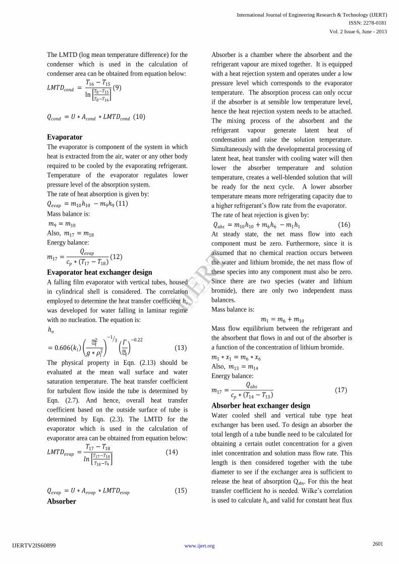
The LMTD (log mean temperature difference) for the
condenser which is used in the calculation of
condenser area can be obtained from equation below:
𝐿𝑀𝑇𝐷𝑐𝑜𝑛𝑑 = 𝑇16 − 𝑇15
ln 𝑇8−𝑇15
𝑇8−𝑇16
(9)
𝑄𝑐𝑜𝑛𝑑 = 𝑈 ∗ 𝐴𝑐𝑜𝑛𝑑 ∗ 𝐿𝑀𝑇𝐷𝑐𝑜𝑛𝑑 (10)
Evaporator
The evaporator is component of the system in which
heat is extracted from the air, water or any other body
required to be cooled by the evaporating refrigerant.
Temperature of the evaporator regulates lower
pressure level of the absorption system.
The rate of heat absorption is given by:
𝑄𝑒𝑣𝑎𝑝 = 𝑚1010 −𝑚99 11
Mass balance is:
𝑚9 = 𝑚10
Also, 𝑚17 = 𝑚18
Energy balance:
𝑚17 =𝑄𝑒𝑣𝑎𝑝
𝑐𝑝 ∗ (𝑇17 − 𝑇18)(12)
Evaporator heat exchanger design
A falling film evaporator with vertical tubes, housed
in cylindrical shell is considered. The correlation
employed to determine the heat transfer coefficient ho
was developed for water falling in laminar regime
with no nucleation. The equation is:
𝑜
= 0.606 𝑘𝑙 µ𝑙
2
𝑔 ∗ 𝜌𝑙2
−13
𝛤
µ𝑙 −0.22
(13)
The physical property in Eqn. (2.13) should be
evaluated at the mean wall surface and water
saturation temperature. The heat transfer coefficient
for turbulent flow inside the tube is determined by
Eqn. (2.7). And hence, overall heat transfer
coefficient based on the outside surface of tube is
determined by Eqn. (2.3). The LMTD for the
evaporator which is used in the calculation of
evaporator area can be obtained from equation below:
𝐿𝑀𝑇𝐷𝑒𝑣𝑎𝑝 =𝑇17 − 𝑇18
𝑙𝑛 𝑇17−𝑇10
𝑇18−𝑇9
(14)
𝑄𝑒𝑣𝑎𝑝 = 𝑈 ∗ 𝐴𝑒𝑣𝑎𝑝 ∗ 𝐿𝑀𝑇𝐷𝑒𝑣𝑎𝑝 (15)
Absorber
Absorber is a chamber where the absorbent and the
refrigerant vapour are mixed together. It is equipped
with a heat rejection system and operates under a low
pressure level which corresponds to the evaporator
temperature. The absorption process can only occur
if the absorber is at sensible low temperature level,
hence the heat rejection system needs to be attached.
The mixing process of the absorbent and the
refrigerant vapour generate latent heat of
condensation and raise the solution temperature.
Simultaneously with the developmental processing of
latent heat, heat transfer with cooling water will then
lower the absorber temperature and solution
temperature, creates a well-blended solution that will
be ready for the next cycle. A lower absorber
temperature means more refrigerating capacity due to
a higher refrigerant’s flow rate from the evaporator.
The rate of heat rejection is given by:
𝑄𝑎𝑏𝑠 = 𝑚1010 + 𝑚66 −𝑚11 (16)
At steady state, the net mass flow into each
component must be zero. Furthermore, since it is
assumed that no chemical reaction occurs between
the water and lithium bromide, the net mass flow of
these species into any component must also be zero.
Since there are two species (water and lithium
bromide), there are only two independent mass
balances.
Mass balance is:
𝑚1 = 𝑚6 + 𝑚10
Mass flow equilibrium between the refrigerant and
the absorbent that flows in and out of the absorber is
a function of the concentration of lithium bromide.
𝑚1 ∗ 𝑥1 = 𝑚6 ∗ 𝑥6
Also, 𝑚13 = 𝑚14
Energy balance:
𝑚17 =𝑄𝑎𝑏𝑠
𝑐𝑝 ∗ 𝑇14 − 𝑇13 (17)
Absorber heat exchanger design
Water cooled shell and vertical tube type heat
exchanger has been used. To design an absorber the
total length of a tube bundle need to be calculated for
obtaining a certain outlet concentration for a given
inlet concentration and solution mass flow rate. This
length is then considered together with the tube
diameter to see if the exchanger area is sufficient to
release the heat of absorption Qabs. For this the heat
transfer coefficient ho is needed. Wilke’s correlation
is used to calculate ho and valid for constant heat flux
2601
International Journal of Engineering Research & Technology (IJERT)
ISSN: 2278-0181
www.ijert.org
Vol. 2 Issue 6, June - 2013
IJERT
IJERT
IJERTV2IS60899
wall with progressively decreasing difference from
isothermal wall outside the entrance region, can be
used for the falling film. It is assumed that the flow is
fully developed in a wavy, laminar regime and that
the bulk solution temperature profile is linear with
respect to the transverse coordinate [6]. The Wilke’s
correlation is:
𝑜 =𝑘𝑠𝛿 0.029 𝑅𝑒𝑠
0.53 𝑃𝑟𝑠 0.344 (18)
Film thickness is given by:
𝛿 = 3µ𝛤
𝜌2𝑔
13
(19)
And the solution Reynolds number:
𝑅𝑒𝑠 =4 ∗ 𝛤
µ(20)
The properties of solution should be evaluated at
temperature of a weak solution and average
concentration of LiBr. The heat transfer coefficient
for turbulent flow inside the tube is determined by
And hence, overall heat transfer coefficient based on
the outside surface of tube is determined by equation.
The LMTD for the absorber which is used in the
calculation of absorber area can be obtained from
equation
𝑄𝑎𝑏𝑠 = 𝑈 ∗ 𝐴𝑎𝑏𝑠 ∗ 𝐿𝑀𝑇𝐷𝑎𝑏𝑠 (21)
Solution Heat Exchanger
A solution heat exchanger is a heat exchange unit
with the purpose of pre-heating the solution before it
enters the generator and removing unwanted heat
from the absorbent. The heat exchange process
within the solution heat exchanger reduces the
amount of heat required from the heat source in the
generator and also reduces the quantity of heat to be
rejected by the heat sink (cooling water) in the
absorber as well. The heat exchange process occurs
between the low temperature of the working fluid and
the high temperature of the absorbent which will
benefit both.
𝑇5 = 𝑇2 휀 + 1 − 휀 𝑇4 (22)
The overall energy balance on the solution heat
exchanger is satisfied if:
𝑚3 3 − 2 = 𝑚4 4 − 5 (23)
Generator
The desorption process generates vapour and extracts
the refrigerant from the working fluid by the addition
of the external heat from the heat source; i.e.
desorption of water out of a lithium bromide-water
solution. The refrigerant vapour travels to the
condenser while the liquid absorbent is
gravitationally settled at the bottom of the generator;
the pressure difference between the generator and the
absorber then causes it to flow out to the absorber
through an expansion valve. The rate of heat addition
in the generator is given by the following equation:
𝑄𝑔𝑒𝑛 = 𝑚77 + 𝑚44 −𝑚33 (24)
Mass balance is
𝑚3 = 𝑚4 + 𝑚7 (25)
And 𝑚3 ∗ 𝑥3 = 𝑚4 ∗ 𝑥4
Also, 𝑚11 = 𝑚12
Energy balance:
𝑚11 =𝑄𝑔𝑒𝑛
𝑐𝑝 ∗ (𝑇11 − 𝑇12) (27)
Generator heat exchanger Design
The falling film type shell and tube heat exchanger is
used as generator. A survey on the literature has not
produced useful correlations for calculating the exact
heat transfer coefficient ho. Nevertheless the mass
transfer characteristics of this kind of exchanger
depend upon a wide range of parameters and in this
regard it is not possible to make any prediction for a
novel design generator. However, for preliminary
design calculation, the value of overall heat transfer
coefficient will be used as 850 W/m2o
C.
The LMTD for the generator which is used in the
calculation of generator area can be obtained from
equation below:
𝐿𝑀𝑇𝐷𝑔𝑒𝑛 =(𝑇11 − 𝑇4) − 𝑇12 − 𝑇7
𝑙𝑛 𝑇11−𝑇4
𝑇12−𝑇7
(28)
𝑄𝑔𝑒𝑛 = 𝑈 ∗ 𝐴𝑔𝑒𝑛 ∗ 𝐿𝑀𝑇𝐷𝑔𝑒𝑛 (29)
Expansion valve
An expansion valve is a component that reduces the
pressure and splits the two different pressure levels.
In a simple model of a single effect absorption
refrigeration system, the pressure change is assumed
only to occur at the expansion valve and the solution
pump. There is no heat added or removed from the
working fluid at the expansion valve. The enthalpy of
2602
International Journal of Engineering Research & Technology (IJERT)
ISSN: 2278-0181
www.ijert.org
Vol. 2 Issue 6, June - 2013
IJERT
IJERT
IJERTV2IS60899

the working fluid remains the same on both sides.
The pressure change process between the two end
points of the expansion valve, while there is no mass
flow change and the process is assumed as an
adiabatic process.
Solution Pump
Although the main distinction between compression
and absorption refrigeration is the replacement of the
mechanically driven system by a heat driven system,
the presence of a mechanically driven component is
still needed in an absorption system. A solution
pump will mainly circulate and lift the solution from
the lower pressure level side to the higher pressure
level side of the system. To maintain this pressure
difference, a centrifugal type pump is preferable.
Assuming the solution is an uncompressible liquid, in
other words the specific volume of the liquid (ν) will
not change during the pumping process, and the
power requirement to lift the solution with mass flow
m1 from pressure level P1 to P2 and certain pump
efficiency is calculated by following equation:
𝑊𝑝𝑢𝑚𝑝 =𝑚1 ∗ 𝑣1 𝑃2 − 𝑃1
𝜂𝑝𝑢𝑚𝑝(30)
COEFFICIENT OF PERFORMANCE
Efficiency of an absorption refrigeration system can
be easily expressed by a Coefficient of Performance
(COP) which is defined as the ratio between the
amount of heat absorbed from the environment by the
evaporator and the heat supplied to the generator to
operate the cycle and pump work.
𝐶𝑂𝑃 =𝑄𝑒𝑣𝑎𝑝
𝑄𝑔𝑒𝑛 +𝑊𝑝𝑢𝑚𝑝(31)
As the work supplied to the absorption system is very
small compared to the amount of heat supplied to the
generator, generally the amount of work is often
excluded from the calculation.
𝐶𝑂𝑃 =𝑄𝑒𝑣𝑎𝑝
𝑄𝑔𝑒𝑛 (Because𝑊𝑝𝑢𝑚𝑝 ≪ 𝑄𝑔𝑒𝑛 )
THE ENTHALPY AND CONCENTRATION
The accurate measurement of enthalpies and
concentration at various state points (from 1 to 10 as
shown in Fig. 2.1) is very important for simulation of
vapour absorption system.
The Enthalpy
The enthalpies of the solution of the refrigerant and
absorbent at points 1 to 6 is a function of the solution
temperature and concentration as given in ASHRAE
chart (Appendix A). For computer simulation
enthalpies at various points can be expressed in multi
variable polynomials in terms of the solution
temperature (T oC) and concentration (X % LiBr).
= 𝐴𝑛𝑋𝑛4
0 + 𝑇 𝐵𝑛𝑋𝑛4
0 + 𝑇2 𝐶𝑛𝑋𝑛4
0
(2.33)
An, Bn and Cn are constant coefficient. In extended
form the above equations can be written as:
= 𝐴0 + 𝐴1𝑋1 + 𝐴2𝑋
2 + 𝐴3𝑋3 + 𝐴4𝑋
4 +
𝑇 𝐵0 + 𝐵1𝑋1 + 𝐵2𝑋
2 + 𝐵3𝑋3 + 𝐵4𝑋
4 +
𝑇2 𝐶0 + 𝐶1𝑋1 + 𝐶2𝑋
2 + 𝐶3𝑋3 + 𝐶4𝑋
4
(2.34)
The value of constants is given in Table 2.1. The
Eqn. (2.44) is valid /applicable if:
Concentration range: 40 %< X<70 % LiBr.
Temperature range: 15 oC< T < 165
oC.
From Fig 3.1: 1 = 2 and 5 = 6
Table 2.1: The value of constants
𝐴0 = −2024.33 𝐵0 = 18.2829 𝐶0 = −3.7𝐸 − 2
𝐴1 = 163.309 𝐵1 = −1.16 𝐶1 = 2.88𝐸 − 3
𝐴2 = −4.88161 𝐵2 = 3.24𝐸 − 2 𝐶2 = −8.15𝐸 − 5
𝐴3 = 6.308𝐸 − 2 𝐵3
= −4.034𝐸 − 4
𝐶3 = 9.9𝐸 − 7
𝐴4 = −2.91𝐸 − 4 𝐵4 = 1.85𝐸 − 6 𝐶4 = −4.4𝐸 − 2
The enthalpies of refrigerant (at state points 7 to 10
as shown in Fig 2.1) are calculated from steam table.
However, for computer simulation enthalpies at
various points can be expressed as [2]:
The enthalpy at exit of generator (state 7) is given as:
7 = 𝐴 + 𝐵 ∗ 𝑇𝑔𝑒𝑛 + 𝐶 ∗ 𝑇𝑔𝑒𝑛2 (2.35)
The value of constant is given as:
A = 2533.996; B = 0.97901595 and C = 0.00493525
The enthalpy at exit of condenser (state 8) is given
as:
8 = 𝐴 + 𝐵 ∗ 𝑇𝑐𝑜𝑛𝑑 + 𝐶 ∗ 𝑇𝑐𝑜𝑛𝑑2
(2.36)
The value of constant is given as:
A = 0.1534285; B = 4.1956286 and C = 0.000257
9 = 8
The enthalpy at exit of evaporator (state 10) is given
as:
10 = 𝐴 + 𝐵 ∗ 𝑇𝑒𝑣𝑎𝑝 + 𝐶 ∗ 𝑇𝑒𝑣𝑎𝑝2
(2.37)
2603
International Journal of Engineering Research & Technology (IJERT)
ISSN: 2278-0181
www.ijert.org
Vol. 2 Issue 6, June - 2013
IJERT
IJERT
IJERTV2IS60899

The value of constant is given as:
A = 2510.2114; B = 1.8614286and C = 0.00071429
The concentration
The solution concentration, “X” is defined as the
ratio of the mass of LiBr to the mass of solution of
water and LiBr. The computation of the
concentration depends upon the temperature. The
concentration is usually determined by ASHRAE
charts, allocating the other two properties of the state
point.
MODELLING OF FLAT PLATE SOLAR
COLLECTOR
In this section a mathematical model is developed to
simulate the flat-plate collector. Various collector
areas are considered and the effect of collector areas
is evaluated against the auxiliary heat required.
In this system inlet hot water temperature is 78 ℃
which is being fed to generator supplied by solar
collector .this temperature is used to heat the weak
solution in generator .FPC (flat plate collector) works
between 30℃ to 90 ℃ temperature due to simple
design of it is recommend for this system
General energy equation for flat plate collector is
given by
𝑄 = 𝐼 × 𝐴𝑐
(2.38)
𝑄 = Amount of solar radiation received by collector
(in W)
𝐼 = Intensity of solar radiation (𝑊/𝑚2)
𝐴𝑐 =Collector surface area (𝑚2)
𝑄 = ṁ × 𝐶𝑝 × (𝑇𝑝 − 𝑇𝑎)
(2.39)
From equation (1) and (2)
ṁ × 𝐶𝑝 × 𝑇𝑝 − 𝑇𝑎 = 𝐼 × 𝐴𝑐
Where 𝑚 = mass flow rate of water flowing in the
tube of collector
Useful heat gain is expressed as
𝑄𝑢 = 𝐹𝑟⦋𝐼 × 𝜏𝛼 × 𝐴𝑐 − 𝑈𝑙 × 𝐴𝑐(𝑇𝑖 − 𝑇𝛼)⦌
ṁ × 𝐶𝑝 × (𝑇11 − 𝑇12)
= 𝐹𝑟⦋𝐼 × 𝜏𝛼 × 𝐴𝑐 − 𝑈𝑙 × 𝐴𝑐(𝑇𝑖− 𝑇𝛼)⦌
𝐹𝑟 = Heat removal factor
𝐹𝑟 =ṁ × 𝐶𝑝 × (𝑇11 − 𝑇12 )
⦋𝐼 × 𝜏𝛼 × 𝐴𝑐 − 𝑈𝑙 × 𝐴𝑐(𝑇𝑖 − 𝑇𝛼)⦌
𝐹𝑟 From duffci and Beckman
𝐹𝑟 = 𝑚 × 𝐶𝑝 × (1 − exp(−𝐴𝑢 × 𝑈𝑙𝑚 × 𝐶𝑝
)
Collector efficiency -
η = 𝑄𝑢𝐼𝐴𝑐
Results
Table 1: Thermodynamic properties of state
points corresponding to input data
state h(kj/kg) m (kg/s) p (kpa) ToC %LiBr
(byweight)
1 58.76 0.0218 1.22 30 49
2 58.76 0.0218 1.22 30 49
3 76.96 0.0218 1.22 38.4 49
4 173.58 0.0178 4.30 70 60
5 150.42 0.0178 4.30 58 60
6 150.43 0.0218 1.22 58 60
7 2626.71 0.004 4.30 70 0
8 126.04 0.004 4.30 30 0
9 126.04 0.004 1.22 30 0
10 2528.89 0.004 1.22 10 0
Table 1: Component Capacities
Evaporator capacity 10.5KW
absorber heat rejected 11.51KW
heat input to generator 11.5KW
condenser heat rejected 10.0KW
COP 0.9130
RESULTS AND DISCUSSION
A mathematical model has been developed
and parametric study of lithium bromide-water
vapour absorption air conditioning system is carried-
out. The effect of generator temperature on ratio of
the rate of solution circulation and on the coefficient
of performance for different condenser temperature,
evaporator temperature, absorber temperature has
been evaluated and discussed. After analysis, the
2604
International Journal of Engineering Research & Technology (IJERT)
ISSN: 2278-0181
www.ijert.org
Vol. 2 Issue 6, June - 2013
IJERT
IJERT
IJERTV2IS60899

design of different component of 10.50 kW, vapour
absorption system i.e. the condenser, evaporator,
absorber, solution heat exchanger and generator has
been presented. Finally, the availability of solar
energy, useful energy and auxiliary heat requirement
for running the absorption air-conditioning system
from 09:00 hrs to 18:00 hrs (9 hours/day) has been
calculated. The above time frame has been selected
judiciously as the energy requirement for cooling
purposes attains its maximum value for months April
to June (Summer Season).
3.1 PARAMETRIC STUDY OF
ABSORPTION SYSTEM
3.1.1 Effect of generator temperature on COP
for different temperature of condenser
Figure 3.1 shows the variation of the coefficient of
performance with generator temperature (Tgen) for
different condenser temperature (Tcond) with absorber
temperature as (Tabs = 30°C) and evaporator
temperature as (Tevap = 10°C). The graph plotted has
been keeping Tcond as 25 oC, 30
oC and 35
oC.From
figure it is evident that the COP initially exhibits an
appreciable increase with the rise in the generator
temperature which results in increase in COP due to
the fact that when generator temperature increases the
mass flow of the refrigerant also increases which
results in increase in cooling capacity and hence COP
of the system increases. However, for Tgen< 65 oC
curve corresponding to condenser temperature (Tcond
= 35 oC) COP is least due to the fact that as Tcond
increases, the condensing temperature increases and
hence causes less heat transfer in the condenser. This
results in an increase in the temperature and in
enthalpy of the refrigerant at the condenser outlet.
Hence, the cooling capacity decreases as does the
COP.
Generator Temperator, oC
55 60 65 70 75 80 85 90
CO
P
0.5
0.6
0.7
0.8
0.9
1.0
Condenser Temperature= 25oC
Condenser Temperature= 30oC
Condenser Temperature= 35oC
Fig. 3.1 Variation of COP with generator
temperature for different condenser temperature
at Tabs = 30°C and Tevap = 10°C.
3.1.2 Effect of generator temperature on
COPfor different temperature of
evaporator
Figure 3.2 shows the variation of generator
temperature (Tgen) with COP respectively for various
evaporator temperature (Tevap) at keeping absorber
temperature as (Tabs=30°C) and condenser
temperature as (Tcond=30°C). The different evaporator
temperatures taken are 8°C, 10°C and 12°C. From the
figure 3.2 it is clear that with increase in Tevap leads to
significant increase in COP.
2605
International Journal of Engineering Research & Technology (IJERT)
ISSN: 2278-0181
www.ijert.org
Vol. 2 Issue 6, June - 2013
IJERT
IJERT
IJERTV2IS60899
Generator Temperator, oC
55 60 65 70 75 80 85 90
CO
P
0.5
0.6
0.7
0.8
0.9
1.0
Evaporator Temperature= 8oC
Evaporator Temperature= 10oC
Evaporator Temperature= 12oC
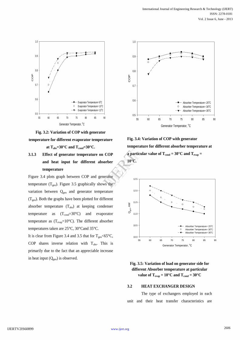
Fig. 3.2: Variation of COP with generator
temperature for different evaporator temperature
at Tabs=30°C and Tcond=30°C.
3.1.3 Effect of generator temperature on COP
and heat input for different absorber
temperature
Figure 3.4 plots graph between COP and generator
temperature (Tgen). Figure 3.5 graphically shows the
variation between Qgen and generator temperature
(Tgen). Both the graphs have been plotted for different
absorber temperature (Tabs) at keeping condenser
temperature as (Tcond=30°C) and evaporator
temperature as (Tevap=10°C). The different absorber
temperatures taken are 25°C, 30°Cand 35°C.
It is clear from Figure 3.4 and 3.5 that for Tgen<65°C,
COP shares inverse relation with Tabs. This is
primarily due to the fact that an appreciable increase
in heat input (Qgen) is observed.
Generator Temperator, oC
55 60 65 70 75 80 85 90
CO
P
0.5
0.6
0.7
0.8
0.9
1.0
Absorber Temperature= 25oC
Absorber Temperature= 30oC
Absorber Temperature= 35oC
Fig. 3.4: Variation of COP with generator
temperature for different absorber temperature at
a particular value of Tcond = 30°C and Tevap =
10°C.
Generator Temperator, oC
55 60 65 70 75 80 85 90
Qg
en, kW
10.0
10.5
11.0
11.5
12.0
12.5
Absorber Temperature= 25oC
Absorber Temperature= 30oC
Absorber Temperature= 35oC
Fig. 3.5: Variation of load on generator side for
different Absorber temperature at particular
value of Tevap = 10°C and Tcond = 30°C
3.2 HEAT EXCHANGER DESIGN
The type of exchangers employed in each
unit and their heat transfer characteristics are
2606
International Journal of Engineering Research & Technology (IJERT)
ISSN: 2278-0181
www.ijert.org
Vol. 2 Issue 6, June - 2013
IJERT
IJERT
IJERTV2IS60899

presented in this section. This is a critical step of
planning a machine and can be rather complex. The
prediction of the overall heat transfer coefficient U is
affected by many uncertainties. A great number of
parameters have effect on the final performance of
the exchangers and unexpected results often arise in
practice. All the components employ shell and tubes
heat exchangers except the solution heat exchanger
which is plate and frame type. Copper used for the
construction of shell and tube heat exchanger and
stainless steel used for plate and frame type heat
exchanger. All the streams coming from the external
circuits flow inside the tubes The thermodynamic
property/condition from state point 1 to 18 (as shown
in Fig. 2.1) required for heat exchanger design is
attached as Annexure – 1.
Table 3.1: Condenser heat exchanger
characteristics
Heat Exchanger Type and
Specifications
Shell and Tube (horizontal
tubes and two tube passes)
Outside diameter (Do)=
0.01905m
Inside diameter (Di)= 0.013m
sMass flow rate of cooling
water (𝑚 15)
1.0 kg/sec
Condenser load (Qcond) 10 kW
LMTD 1.3 ℃
Overall heat transfer
coefficient (U)
2.05 kW/m2oC
Area 3.531 m2
Length of tube 1.843 𝑚
No. of tubes used 16
Table 3.2: Evaporator heat exchanger
characteristics
Mass flow rate of
water (𝑚 17)
0.084 kg/sec
Evaporator
capacity (Qevap)
10.50 kW
Area 3.733m2
Length and number
of tubes
2 m, 16
Table 3.3: Absorber heat exchanger
characteristics
Heat Exchanger Type
and Specifications
Shell and Tube (Vertical
tubes and four tube
passes)
Outside diameter (Do)=
0.01905m
Inside diameter (Di)=
0.013m
Mass flow rate of
cooling water (𝑚 13)
1kg/sec
Absorber heat rejection
(Qabs)
11.51 kW
LMTD 3.3
Overall heat transfer
coefficient (U)
1820.2 W/m2o
C
Area 1.91 m2
Length and number of
tubes
1m, 16 m
2607
International Journal of Engineering Research & Technology (IJERT)
ISSN: 2278-0181
www.ijert.org
Vol. 2 Issue 6, June - 2013
IJERT
IJERT
IJERTV2IS60899
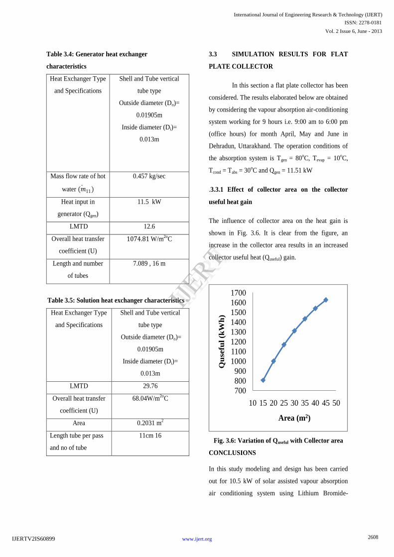
Table 3.4: Generator heat exchanger
characteristics
Heat Exchanger Type
and Specifications
Shell and Tube vertical
tube type
Outside diameter (Do)=
0.01905m
Inside diameter (Di)=
0.013m
Mass flow rate of hot
water (𝑚 11)
0.457 kg/sec
Heat input in
generator (Qgen)
11.5 kW
LMTD 12.6
Overall heat transfer
coefficient (U)
1074.81 W/m2o
C
Length and number
of tubes
7.089 , 16 m
Table 3.5: Solution heat exchanger characteristics
Heat Exchanger Type
and Specifications
Shell and Tube vertical
tube type
Outside diameter (Do)=
0.01905m
Inside diameter (Di)=
0.013m
LMTD 29.76
Overall heat transfer
coefficient (U)
68.04W/m2o
C
Area 0.2031 m2
Length tube per pass
and no of tube
11cm 16
3.3 SIMULATION RESULTS FOR FLAT
PLATE COLLECTOR
In this section a flat plate collector has been
considered. The results elaborated below are obtained
by considering the vapour absorption air-conditioning
system working for 9 hours i.e. 9:00 am to 6:00 pm
(office hours) for month April, May and June in
Dehradun, Uttarakhand. The operation conditions of
the absorption system is Tgen = 80oC, Tevap = 10
oC,
Tcond = Tabs = 30oC and Qgen = 11.51 kW
.3.3.1 Effect of collector area on the collector
useful heat gain
The influence of collector area on the heat gain is
shown in Fig. 3.6. It is clear from the figure, an
increase in the collector area results in an increased
collector useful heat (Quseful) gain.
Fig. 3.6: Variation of Quseful with Collector area
CONCLUSIONS
In this study modeling and design has been carried
out for 10.5 kW of solar assisted vapour absorption
air conditioning system using Lithium Bromide-
700
800
900
1000
1100
1200
1300
1400
1500
1600
1700
10 15 20 25 30 35 40 45 50
Qu
sefu
l (k
Wh
)
Area (m2)
2608
International Journal of Engineering Research & Technology (IJERT)
ISSN: 2278-0181
www.ijert.org
Vol. 2 Issue 6, June - 2013
IJERT
IJERT
IJERTV2IS60899

Water as refrigerant. Also parametric study has been
carried out to study the effect of condenser
temperature, generator temperature, evaporator
temperature, absorber temperature on co-efficient of
performance (COP) and effect of generator
temperature on specific solution circulation rates (f).
On the basis of the parametric study the different
components of vapour absorption refrigeration
system i.e. condenser, evaporator, absorber and
solution heat exchanger has been designed. Also the
availability of solar energy for running the air-
conditioning system for 09 hours i.e. 09:00 hrs to
18:00 hrs (office hours) for April, May and June in
Dehradun, Uttarakhand has been studied. The above
time frame was selected judiciously as the energy
requirement for cooling purposes attains its
maximum value for months April to June (Summer
Season).
Based upon the study following conclusions have
been drawn:
1. A model has been developed which can
predict the COP of the system. Each
component of the absorption system i.e.
generator, condenser, evaporator and
absorber has been designed.
2. Higher evaporator and generator
temperature, results in higher coefficient of
performance (COP) of the system due to the
fact that as generator temperature increases,
the heat transfer to the solution in the
generator increases, result in the increase of
mass flow rate and so does the COP.
3. Low condensing temperature results in
higher COP due to the fact that as Tcond
increases, the condensing temperature
increases and hence causes less heat transfer
in the condenser, which results in an
increase in temperature and enthalpy of the
refrigerant at the condenser outlet. Hence,
the cooling capacity decreases as does the
COP.
4. For generator temperature from 65°C to
80°C, the absorption system work
efficiently.
REFERENCES
1. Horuz I. “A comparison between ammonia-
water and water-lithium bromide solution in
vapour refrigeration systems”, Int. Comm.
Heat mass transfer, 1998; 25: 711-721.
2. Mittal V., Kasana K.S. and Thakur N. S.
“Modelling and simulation of a solar
absorption cooling system for India”,
Journal of Energy in Southern Africa, 2006;
17: 65-70.
3. Mehrabian M. A. and Shahbeik A. E.
“Thermodynamic modelling of a single-
effect LiBr-H2O absorption refrigeration
cycle”, Journal of process Mechanical
Engineering, 2005; 219:261-273.
4. Alva L. H. and Gonzalez J. E. “Simulation
of an air-cooled solar-assisted absorption air
conditioning system”, Solar energy
proceedings of forum, 2001.
5. Hammad M. A. and Audi M. S.
“Performance of a solar LiBr-H2O water
absorption refrigeration system”, Renewable
energy, 1992; 2:275-282.
6. Kalogirou S., Florides G., Tassou S. and
Wrobel L., “Design and construction of a
lithium bromide water absorption
refrigerator”, CLIMA2000/Napoli world
congress; 2001.
7. Martinez P. J. and Pinazo J. M. “A method
for design analysis of absorption machines”,
International journal of refrigeration, 2002;
25:634-639.
8. Boumaza M. and Mujtaba I. M.
“Thermodynamic analysis of refrigeration
absorption system”, Intrnational conference
2609
International Journal of Engineering Research & Technology (IJERT)
ISSN: 2278-0181
www.ijert.org
Vol. 2 Issue 6, June - 2013
IJERT
IJERT
IJERTV2IS60899

on advance in mechanical and material e.g.,
2005; 181-188.
9. Sun D. W. “Thermodynamic design data and
optimum design maps for absorption
refrigeration system”, Applied Thermal
Engineering, 1996; 17:211-221.
10. Assilzadeha F., Kalogiroub S.A., Ali Y. and
Sopiana K. “Simulation and optimization of
a LiBr solar absorption cooling system with
evacuated tube collectors”, Renewable
energy, 2005; 30:1143-1159.
11. Zhai X.Q., Wang R. Z., Wu J. Y., Dai Y.J.
and Ma Q. “Design and performance of a
solar-powered air-conditioning system in a
green building”, Applied energy, 2008;
85:297-311.
12. Pongtornkulpanich A., Thepa S.,
Amornkitbamrung M., Butcher C.
“Experience with fully operational solar-
driven 10-ton LiBr/H2O single effect
absorption cooling system in Thailand”,
Renewable energy,2007; 33:943-949.
13. Li Z. F. and Sumathy K. “Technology
development in the solar absorption air-
conditioning systems”, Renewable and
suitable energy reviews, 2000; 4:267-293.
14. Florides G. A., Kalogirou S. A., Tassou S.
A. and Wrobel L.C. “Modelling, simulation
and warming impact assessment of a
domestic-size absorption solar cooling
system”, Applied thermal engineering, 2002;
22:1313-1325.
15. Izquierdo M., Lizarte R., Marcos J.D. and
Gutierrez G. “Air conditioning using an air-
cooled single effect lithium bromide
absorption chiller”, Applied thermal
engineering, 2008; 28:1074-1081.
16. Syeda A., Izquierdod M., Rodrigueze P.,
Maidment G., Missendenb J., Lecuonae A.
and Tozer R. “A novel experimental
investigation of a solar cooling system in
Madrid”, International journal of
refrigeration, 2005; 28: 859-871.
2610
International Journal of Engineering Research & Technology (IJERT)
ISSN: 2278-0181
www.ijert.org
Vol. 2 Issue 6, June - 2013
IJERT
IJERT
IJERTV2IS60899