design analysis - dominguezdesign-build.com · structural design shall be in accordance with ......
TRANSCRIPT

CONTRACT NO. HSCG82-17-C-PMV269
INSTALL NEW FUEL SYSTEMS
At
USCG Station Pascagoula, MS
DESIGN ANALYSIS FINAL SUBMITTAL
PREPARED BY:
Peterson Engineering, Inc.
75 South F Street Pensacola, Florida 32502
Mechanical: Peterson Engineering, Inc. Electrical: Bagwell Engineering, Inc. Structural: McCarthy Engineering, Inc. General Contractor: Dominguez Design-Build, Inc.
APPROVED BY:
For COMMANDING OFFICER, CIVIL ENGINEERING UNIT MIAMI: Date:
Submitted By: Gregory D. Peterson, P.E. Date: 30 March 2018
TABLE OF CONTENTS I. RESPONSES TO COMMENTS II. STRUCTURAL DESIGN NARRATIVE III. MECHANICAL DESIGN NARRATIVE IV. ELECTRICAL DESIGN NARRATIVE

I. RESPONSES TO COMMENTS
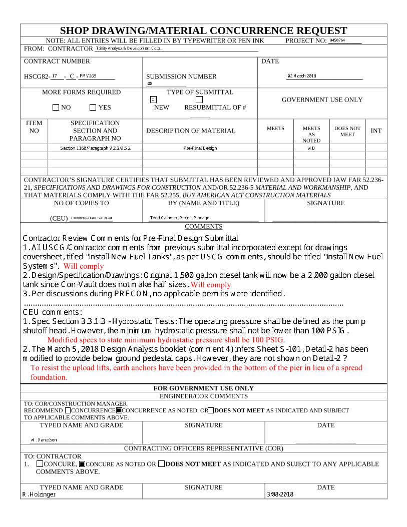
SHOP DRAWING/MATERIAL CONCURRENCE REQUEST NOTE: ALL ENTRIES WILL BE FILLED IN BY TYPEWRITER OR PEN INK PROJECT NO: __________
FROM: CONTRACTOR _________________________________________________
CONTRACT NUMBER
HSCG82-____-___-___________ SUBMISSION NUMBER ____________
DATE
_______________________
MORE FORMS REQUIRED
NO YES
TYPE OF SUBMITTAL
NEW RESUBMITTAL OF # ______
GOVERNMENT USE ONLY
ITEM NO
SPECIFICATION SECTION AND
PARAGRAPH NO DESCRIPTION OF MATERIAL MEETS MEETS
AS NOTED
DOES NOT MEET INT
CONTRACTOR’S SIGNATURE CERTIFIES THAT SUBMITTAL HAS BEEN REVIEWED AND APPROVED IAW FAR 52.236-21, SPECIFICATIONS AND DRAWINGS FOR CONSTRUCTION AND/OR 52.236-5 MATERIAL AND WORKMANSHIP, AND THAT MATERIALS COMPLY WITH THE FAR 52.255, BUY AMERICAN ACT CONSTRUCTION MATERIALS
NO OF COPIES TO
(CEU) _____________
BY (NAME AND TITLE)
_________________________________
SIGNATURE
________________________________ COMMENTS
FOR GOVERNMENT USE ONLY ENGINEER/COR COMMENTS
TO: COR/CONSTRUCTION MANAGER RECOMMEND CONCURRENCE, CONCURRENCE AS NOTED. OR DOES NOT MEET AS INDICATED AND SUBJECT TO APPLICABLE COMMENTS ABOVE.
TYPED NAME AND GRADE
_______________________________
SIGNATURE
________________________________
DATE
__________________ CONTRACTING OFFICERS REPRESENTATIVE (COR)
TO: CONTRACTOR 1. CONCURE, CONCURE AS NOTED OR DOES NOT MEET AS INDICATED AND SUJECT TO ANY APPLICABLE
COMMENTS ABOVE.
TYPED NAME AND GRADE SIGNATURE DATE
C
Will comply
Will comply
Modified specs to state minimum hydrostatic pressure shall be 100 PSIG.
To resist the upload lifts, earth anchors have been provided in the bottom of the pier in lieu of a spread foundation.

II. STRUCTURAL DESIGN NARRATIVE

INSTALL NEW FUEL SYSTEMS HSCG82-17-C-PMV269 USCG STATION PASCAGOULA, MS
Structural Design Analysis
STRUCTURAL DESIGN ANALYSIS FINAL SUBMITTAL
100% Submittal / Critical Path Final Submittal
1. STRUCTURAL SYSTEMS
A. General: The proposed project includes a new foundation system to support new fuel tanks and associated equipment. The foundation has been designed to resist the imposed loading conditions. Final grades shall be verified in field and minimum turndown dimensions shall extend 1’-6” below grade.
B. Design Criteria: The project is located in Mississippi. The structure shall be analyzed, designed, fabricated, and constructed in accordance with the applicable edition of the following criteria. In the case of conflict within these requirements, the most stringent requirement will govern. Structural design shall be in accordance with the criteria, requirements.
• ACI 315: American Concrete Institute, Manual of Standard Practice for Detailing Reinforced Concrete Structures
• ACI 318-14: American Concrete Institute, Building Code Requirements for Structural Concrete and Commentary.
• ACI 360 R-06: Design of Slabs on Ground
• ASCE 7-10: Minimum Design Loads for Buildings and Other Structures.
• AWS D1.1: American Welding Society, Structural Welding Code – Steel.
• IBC 2015: International Building Code, 2015 Edition.
• UFC 1-200-01: Unified Facilities Criteria (UFC), General Building Requirements, 28 November 2011
• UFC 3-301-01: Unified Facilities Criteria (UFC), Structural Engineering 1 June 2013
C. Design Basis:
Design loads and load combinations shall be in accordance with the requirements of ASCE 7-10, as a minimum, unless otherwise specified herein. Design for seismic loads shall comply with IBC 2015.
D. Design Loads:
• Earthquake: IBC 2015. Use Short Period Ss=0.10g and One Second Period S1=0.06g. Seismic Risk Category shall be IV. Site Soil Classification is assumed to be “D”.
• Wind: ASCE 7-10. 178 mph, 3 sec. Gust speed. Exposure “D”, Risk Category shall be IV.
Uniform Concentrated

INSTALL NEW FUEL SYSTEMS HSCG82-17-C-PMV269 USCG STATION PASCAGOULA, MS
Structural Design Analysis
Slab-on-Grade (Unless Noted Otherwise) 50,000 lbs
E. Minimum Material Properties:
• Concrete in footings/ slab on grade: f’c = 3500 psi F. Foundations and Slabs on Ground:
• Materials: The minimum required construction for concrete slabs on ground shall be 12” thick concrete, reinforced minimum #6 reinforcing steel each way top and bottom.
• The foundation system shall consist of reinforced concrete shallow foundations and/ or combined spread footings.
G. Support of Non-Structural Items:
• All mechanical and electrical equipment and other auxiliary building features such as ductwork, piping, cable trays, etc. shall be properly supported. All equipment and architectural features shall be adequately framed, reinforced, and connected.

III. MECHANICAL DESIGN NARRATIVE

INSTALL NEW FUEL SYSTEMS HSCG82-17-C-PMV269 USCG STATION PASCAGOULA, MS
MECHANICAL DESIGN NARRATIVE 1
MECHANICAL DESIGN ANALYSIS FINAL SUBMITTAL
Applicable Criteria:
• International Building Code, 2015 IAW UFC 1-200-01. • American Society of Mechanical Engineers(ASME) BPVC Section IX – Welding,
Brazing, and Fusing Qualifications • American Society for Testing and Materials (ASTM) • American Welding Society Z49.1 – Safety in Welding, Cutting, and Allied
Processes • American Welding Society A5.4 – Specification for Stainless Steel Electrodes for
Shielded Metal Arc Welding • NFPA 30 – Flammable and Combustible Liquids Code • NFPA 30A – Motor Fuel Dispensing Facilities and Repair Garages
Demolition Mechanical: The existing 1000 gallon gasoline fuel tank and 1500 gallon diesel tank will be abandoned. The existing fuel lines and sidewalk containment sump shall be abandoned in place. New Mechanical: One new 1000 gallon gasoline fuel tank and one 2000 gallon diesel fuel tank will be installed on new concrete pad. New fuel pumps will be installed at each fuel tank. New above ground stainless steel piping will be installed from fuel tanks to tie-in points to existing piping located at the start of the pier. Existing fuel dispensers will remain as-is.

INSTALL NEW FUEL SYSTEMS HSCG82-17-C-PMV269 USCG STATION PASCAGOULA, MS
MECHANICAL DESIGN NARRATIVE
MECHANICAL EQUIPMENT CUT SHEETS
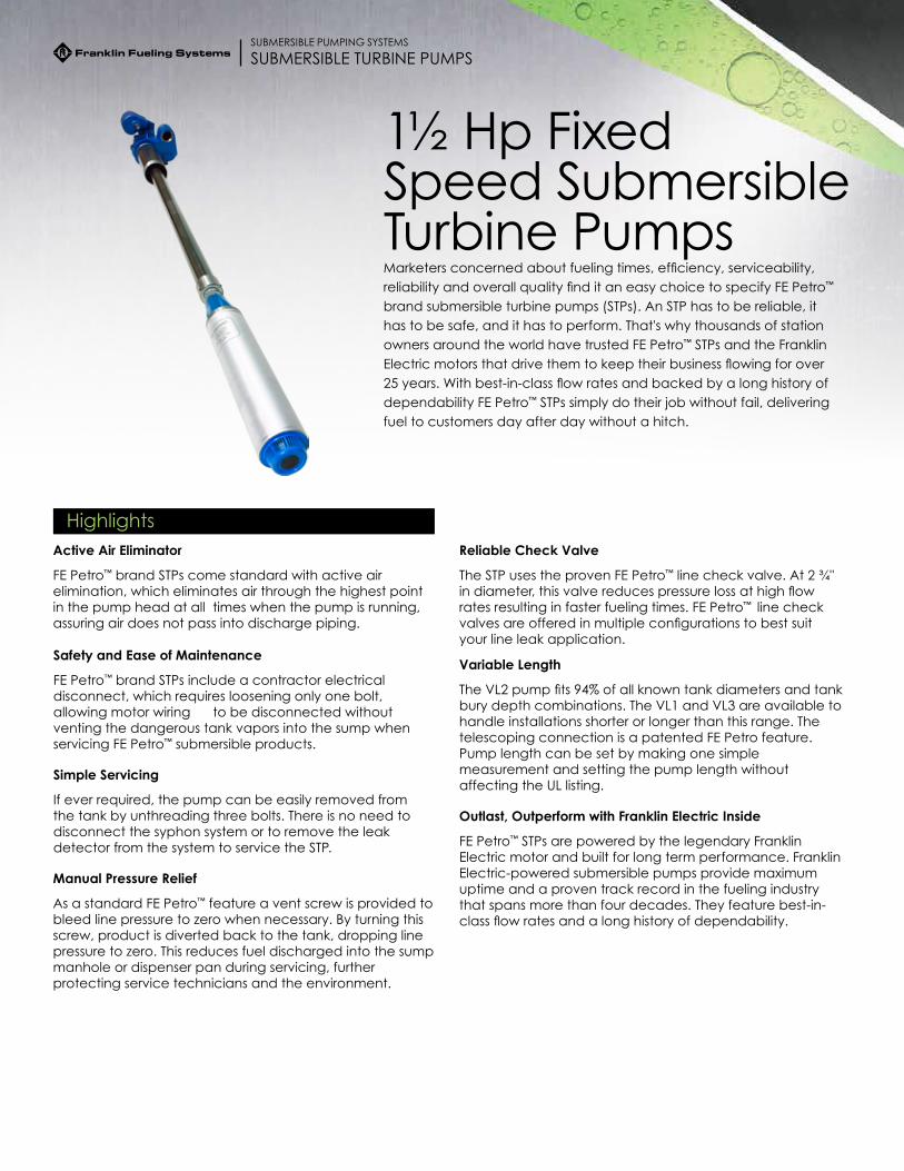
Marketers concerned about fueling times, efficiency, serviceability, reliability and overall quality find it an easy choice to specify FE Petro™ brand submersible turbine pumps (STPs). An STP has to be reliable, it has to be safe, and it has to perform. That's why thousands of station owners around the world have trusted FE Petro™ STPs and the Franklin Electric motors that drive them to keep their business flowing for over 25 years. With best-in-class flow rates and backed by a long history of dependability FE Petro™ STPs simply do their job without fail, delivering fuel to customers day after day without a hitch.
Highlights
SUBMERSIBLE TURBINE PUMPS
1½ Hp Fixed Speed Submersible Turbine Pumps
SUBMERSIBLE PUMPING SYSTEMS
Active Air Eliminator
FE Petro™ brand STPs come standard with active air elimination, which eliminates air through the highest point in the pump head at all times when the pump is running, assuring air does not pass into discharge piping.
Manual Pressure Relief
As a standard FE Petro™ feature a vent screw is provided to bleed line pressure to zero when necessary. By turning this screw, product is diverted back to the tank, dropping line pressure to zero. This reduces fuel discharged into the sump manhole or dispenser pan during servicing, further protecting service technicians and the environment.
Safety and Ease of Maintenance
FE Petro™ brand STPs include a contractor electrical disconnect, which requires loosening only one bolt, allowing motor wiring to be disconnected without venting the dangerous tank vapors into the sump when servicing FE Petro™ submersible products.
Simple Servicing
If ever required, the pump can be easily removed from the tank by unthreading three bolts. There is no need to disconnect the syphon system or to remove the leak detector from the system to service the STP.
Variable Length
The VL2 pump fits 94% of all known tank diameters and tank bury depth combinations. The VL1 and VL3 are available to handle installations shorter or longer than this range. The telescoping connection is a patented FE Petro feature. Pump length can be set by making one simple measurement and setting the pump length without affecting the UL listing.
Reliable Check Valve
The STP uses the proven FE Petro™ line check valve. At 2 ¾" in diameter, this valve reduces pressure loss at high flow rates resulting in faster fueling times. FE Petro™ line check valves are offered in multiple configurations to best suit your line leak application.
Outlast, Outperform with Franklin Electric Inside
FE Petro™ STPs are powered by the legendary Franklin Electric motor and built for long term performance. Franklin Electric-powered submersible pumps provide maximum uptime and a proven track record in the fueling industry that spans more than four decades. They feature best-in-class flow rates and a long history of dependability.
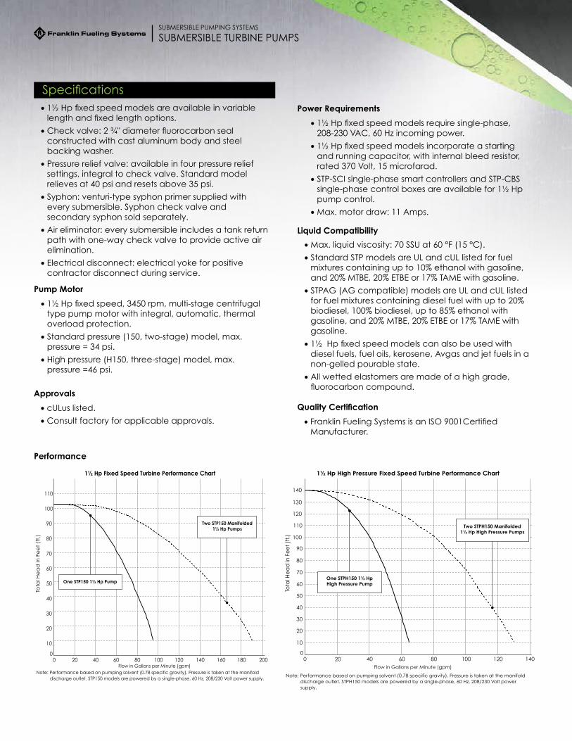
SpecificationsPower Requirements
• 1½ Hp fixed speed models require single-phase, 208-230 VAC, 60 Hz incoming power.
• 1½ Hp fixed speed models incorporate a starting and running capacitor, with internal bleed resistor, rated 370 Volt, 15 microfarad.
• STP-SCI single-phase smart controllers and STP-CBS single-phase control boxes are available for 1½ Hp pump control.
• Max. motor draw: 11 Amps.
Pump Motor
• 1½ Hp fixed speed, 3450 rpm, multi-stage centrifugal type pump motor with integral, automatic, thermal overload protection.
• Standard pressure (150, two-stage) model, max. pressure = 34 psi.
• High pressure (H150, three-stage) model, max. pressure =46 psi.
Liquid Compatibility
• 1½ Hp fixed speed models are available in variable length and fixed length options.
• Check valve: 2 ¾" diameter fluorocarbon seal constructed with cast aluminum body and steel backing washer.
• Pressure relief valve: available in four pressure relief settings, integral to check valve. Standard model relieves at 40 psi and resets above 35 psi.
• Syphon: venturi-type syphon primer supplied with every submersible. Syphon check valve and secondary syphon sold separately.
• Air eliminator: every submersible includes a tank return path with one-way check valve to provide active air elimination.
• Electrical disconnect: electrical yoke for positive contractor disconnect during service.
SUBMERSIBLE TURBINE PUMPSSUBMERSIBLE PUMPING SYSTEMS
Approvals
• cULus listed.
• Consult factory for applicable approvals.
Quality Certification
• Franklin Fueling Systems is an ISO 9001Certified Manufacturer.
• Max. liquid viscosity: 70 SSU at 60 °F (15 °C).
• Standard STP models are UL and cUL listed for fuel mixtures containing up to 10% ethanol with gasoline, and 20% MTBE, 20% ETBE or 17% TAME with gasoline.
• STPAG (AG compatible) models are UL and cUL listed for fuel mixtures containing diesel fuel with up to 20% biodiesel, 100% biodiesel, up to 85% ethanol with gasoline, and 20% MTBE, 20% ETBE or 17% TAME with gasoline.
• 1½ Hp fixed speed models can also be used with diesel fuels, fuel oils, kerosene, Avgas and jet fuels in a non-gelled pourable state.
• All wetted elastomers are made of a high grade, fluorocarbon compound.
Performance
1½ Hp Fixed Speed Turbine Performance Chart
0
10
20
30
40
50
60
70
80
90
100
110
0 20 40 60 80 100 120 140 160 180 200Flow in Gallons per Minute (gpm)
Tota
l He
ad
in F
ee
t (f
t.)
Note: Performance based on pumping solvent (0.78 specific gravity). Pressure is taken at the manifold discharge outlet. STP150 models are powered by a single-phase, 60 Hz, 208/230 Volt power supply.
Two STP150 Manifolded1½ Hp Pumps
One STP150 1½ Hp Pump
1½ Hp High Pressure Fixed Speed Turbine Performance Chart
0
10
20
30
40
50
60
70
80
90
100
110
120
130
140
0 20 40 60 80 100 120 140Flow in Gallons per Minute (gpm)
Tota
l He
ad
in F
ee
t (f
t.)
Note: Performance based on pumping solvent (0.78 specific gravity). Pressure is taken at the manifold discharge outlet. STPH150 models are powered by a single-phase, 60 Hz, 208/230 Volt power supply.
One STPH150 1½ Hp High Pressure Pump
Two STPH150 Manifolded 1½ Hp High Pressure Pumps

Ordering Information
STP XXXXX Y - A - B
STP = Basic Model Designation
XXXXX = Factory Installed Options (Model designations may include one or more of the following characters in alphabetical order.)
AG = Alcohol-gasoline compatible (up to E85, up to B20, and B100) (Note standard models up to 10% ethanol capable)
F = Floating suction adapter (1½" NPT female adapter)
K = Intake filter screen (IFS, factory installed to PMA)
M = MagShell™ (flow enhancing, expanded PMA shell)
*R = Model R check valve (24 psi relief/22 psi reset for PLLD)
*W = Model W check valve (16 psi relief/13 psi reset for PPM4000)
Y = Pump Motor Horsepower Rating
150 = 1½ Hp fixed speed
A = Model Length (see table)
VL1 = Variable length range #1.
VL2 = Variable length range #2.
VL3 = Variable length range #3.
(Note VL2 models fit 94% of all known installations)
B = Riser Pipe Length (see diagram)
Riser pipe length is expressed as two numeric characters that indicate the total length of the riser in inches. Riser pipes are available from 7" to 69" in 1" increments (additional charge for risers 31" or longer).
Notes:
*If not otherwise specified, all STP models are supplied with standard model check valve (40 psi relief /35 psi reset for MLD, TS-LS300, and TS-LS500).
A typical turbine model designation has up to five components to define the pump being supplied as follows:
B
A
LU
SYPH
ONT
K
SUBMERSIBLE TURBINE PUMPSSUBMERSIBLE PUMPING SYSTEMS
STP Horsepower
Model Length Range
Model Length Designation
2 Hp
60" - 88" VL1
91" - 152" VL2
123" - 214" VL3
2 Hp high pressure
61" - 89" VL1
92" - 152" VL2
124" - 215" VL3
Model Length (A)

Standard 1½ Hp Fixed Speed Submersible Turbine Pumps
Model Description Model Length Range Number
Model Length Range*
STP150-VL1 1½ Hp fixed speed VL1 60"-88"
STP150-VL2 1½ Hp fixed speed VL2 91"-152"
STP150-VL3 1½ Hp fixed speed VL3 123"-214"
STPH150-VL1 1½ Hp high pressure fixed speed VL1 61"-89"
STPH150-VL2 1½ Hp high pressure fixed speed VL2 92"-152"
STPH150-VL3 1½ Hp high pressure fixed speed VL3 124"-215"
Notes:
1. STP models are compatible with fuel mixtures containing up to 10% ethanol with gasoline, diesel fuels, and 20% MTBE, 20% ETBE or 17% TAME with gasoline. STPAG models are compatible with fuel mixtures containing diesel fuel with up to 20% biodiesel, 100% biodiesel, up to 85% ethanol with gasoline, and 20% MTBE, 20% ETBE or 17% TAME with gasoline.
2. All models are supplied with a standard check valve unless factory option "R" or "W" is specified.
3. All above models require single-phase, 208-230 VAC, 60 Hz incoming power.
4. 4" riser pipe, if supplied locally, must be 4½" OD by 3/16" WT tubing.
5. For riser pipe lengths 31" to 69", additional charges apply.
*Model length (A) defined as the dimension from turbine manifold bottom to pump motor inlet.
SUBMERSIBLE TURBINE PUMPSSUBMERSIBLE PUMPING SYSTEMS
Ordering Information continued
Factory Installed Options
Model Description
F Floating suction adapter, 1½" NPT female, must be factory installed
K IFS (intake filter screen) factory assembled to pump motor assembly
R Model R check valve, factory installed, for Veeder-Root™ PLLD Line Leak
W Model W check valve, factory installed, for Red Jacket PPM4000 Line Leak
Specified in model number at time of STP order.
Alcohol-Gas (AG) 1½ Hp Fixed Speed Submersible Turbine Pumps
Model Description Model Length Range Number
Model Length Range*
STPAG150-VL1 1½ Hp AG fixed speed VL1 60"-88"
STPAG150-VL2 1½ Hp AG fixed speed VL2 91"-152"
STPAG150-VL3 1½ Hp AG fixed speed VL3 123"-214"
STPAGH150-VL1 1½ Hp AG high pressure fixed speed VL1 61"-89"
STPAGH150-VL2 1½ Hp AG high pressure fixed speed VL2 92"-152"
STPAGH150-VL3 1½ Hp AG high pressure fixed speed VL3 124"-215"

Field Installed Options
Model Description
400137908 Syphon check valve, alcohol-gasoline compatible (when ordered with STP)
400818921 STP-CBS, single-phase control box with lockout switch, 110 Volt coil
402312921 STP-DHI-SCI, combo DHI with factory wired STP-SCI (when purchased with a 4" STP)*
402312921 STP-DHI-SCI, combo DHI with factory wired STP-SCI (when purchased without a 4" STP)
402313921 STP-DHI-CBS, combo DHI with factory wired STP-CBS
402459931 Model 65 psi check valve (for slave of manifolded STPs with Veeder-Root™ PLLD)
402507930 Secondary syphon kit (when two syphon primes are required for one STP)
5800100215 STP-SCI, single-phase smart controller (when purchased without a 4" STP)
5800100215 STP-SCI, single-phase smart controller (when purchased with a 4" STP)*
5800300100 STP-DHI, dispenser hook isolation for 110 Volt dispenser handle switches, up to eight each
1½ Hp fixed speed specific accessories.
FFS-0379 07-14 Veeder-Root™ is a trademark of the Danaher Corporation.
3760 Marsh Rd. • Madison, WI 53718, USATel: +1 608 838 8786 • Fax: +1 608 838 6433Tel: USA & Canada +1 800 225 9787 • Tel: UK +44 (0)1473 243300
franklinfueling.com
Tel: Mex 001 800 738 7610 • Tel: FR +33 (0)1 69 21 41 41 • Tel: CH +86 10 8565 4566
A Franklin Fueling Systems Brand
SUBMERSIBLE TURBINE PUMPSSUBMERSIBLE PUMPING SYSTEMS
Ordering Information continued
*When purchasing STP-SCI or STP-DHI-SCI in equal quantities of fixed speed 4" STPs, the STP-SCI or STP-DHI-SCI will be invoiced at special discount pricing.
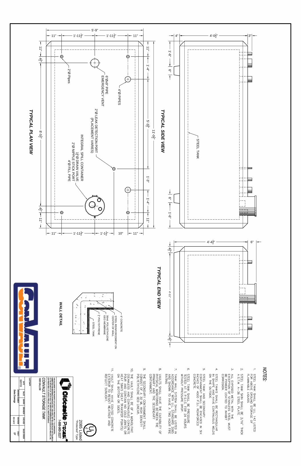
4'-11"
4'-012"4"
1'-6"6"
3"
4'-412"
1'-6"6"
412 "
6"
412 "
1'-112"
5'-9"
1'-1112"
8'-512 "
11"
11" 1'-1112"
412 "
2"Ø P
ipes
412 "
11"
1'-1112"11"
11'-012 "
5'-312 "
11"
11"1'-4"
10"
1'-4"1'-3"
11"
11"
STE
EL TA
NK
4"Ø P
IPE
S
6"Øx9" P
IPE
EM
ER
GE
NC
Y V
EN
T
2"Ø LE
AK
DE
TEC
TION
P0R
T(P
LAC
EM
EN
T VA
RIE
S)
INTE
GR
AL S
PILL C
ON
TAIN
ER
112 "Ø
DR
AIN
VA
LVE
2"Ø N
IPP
LE S
TICK
PO
RT
4"Ø FILL P
IPE
TYPICA
L SIDE VIEW
TYPICA
L END
VIEW
TYPICA
L PLAN
VIEW
STE
EL TAN
K
14 " PO
LYS
TYREN
E
30mil. P
OLY
ETH
YLENE
GE
O M
EM
BRAN
E
STE
EL R
EIN
FOR
CEM
ENT O
NC
EN
TER
OF W
ALL
6" CO
NC
RETE
WA
LL DETA
IL
"Protected" Type2085 Listed
L Ud
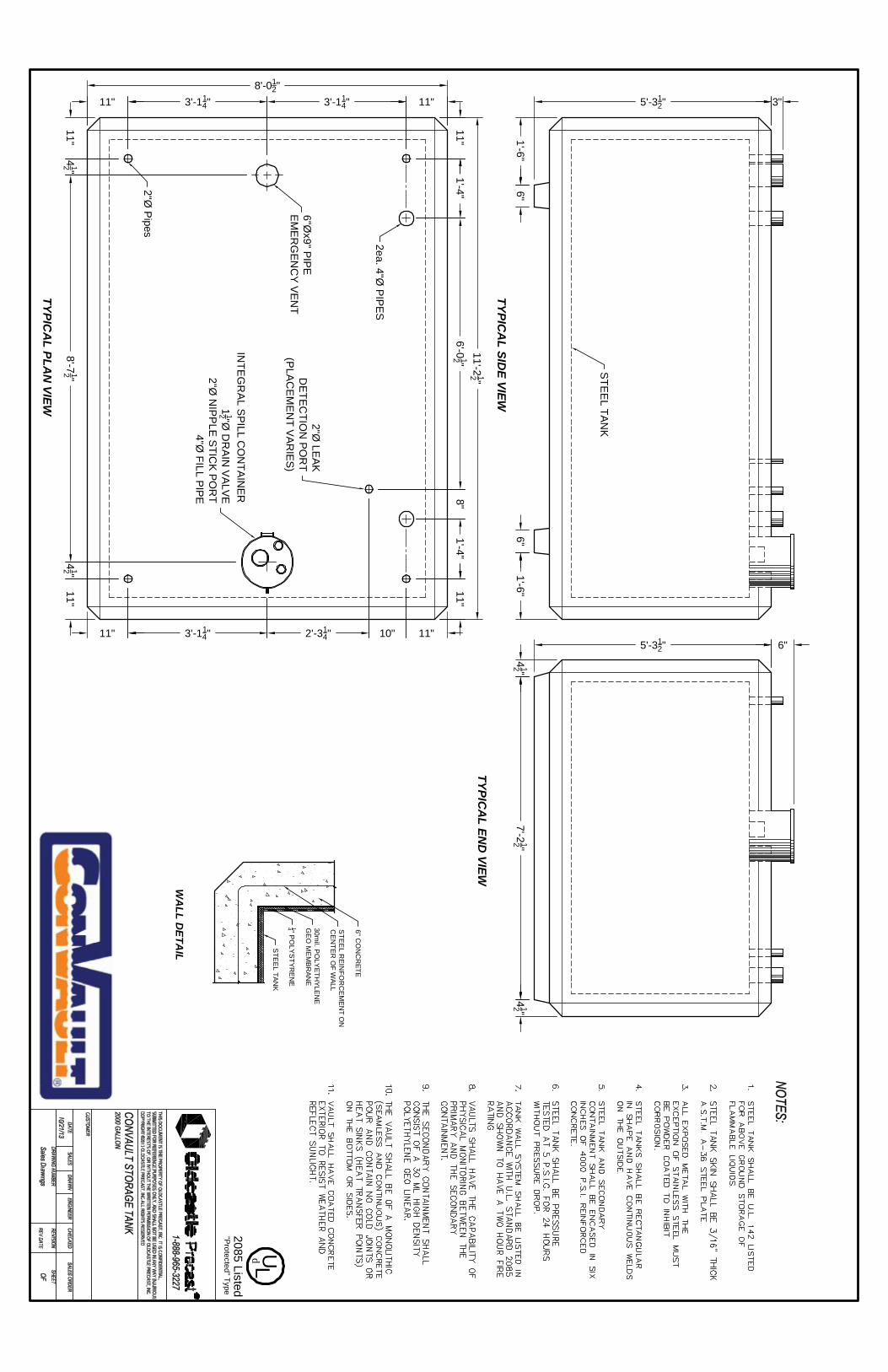
7'-212 "
6"
5'-312"
1'-6"6"
3"
5'-312"
1'-6"6"
412 "
412 "
2'-314"
8'-012"
3'-114"
8'-712 "
11"
11" 3'-114"
412 "
2"Ø P
ipes
412 "
3'-114"11"
11"
11'-212 "
6'-012 "
11"
11"1'-4"
10"
1'-4"8"
11"
11"
STE
EL TAN
K
2ea. 4"Ø P
IPES
2"Ø LEAK
DETEC
TION
POR
T(P
LAC
EM
EN
T VARIES)
6"Øx9" PIPE
EM
ER
GEN
CY
VEN
T
INTE
GR
AL S
PILL C
ON
TAINER
112 "Ø
DR
AIN
VALVE2"Ø
NIP
PLE
STIC
K POR
T4"Ø
FILL PIPE
TYPICA
L SIDE VIEW
TYPICA
L END
VIEW
TYPICA
L PLAN
VIEW
STE
EL TAN
K
14 " PO
LYS
TYREN
E
30mil. P
OLY
ETH
YLENE
GE
O M
EM
BRAN
E
STE
EL R
EIN
FOR
CEM
ENT O
NC
EN
TER
OF W
ALL
6" CO
NC
RETE
WA
LL DETA
IL
"Protected" Type2085 Listed
L Ud


The Aboveground Solution to the Underground Problem
Interest in the preservation of our environment has prompted all levels of many governments to issue strict guidelines for the installation, operation and removal of underground storage tanks (UST’s). As a result, owners and operators are faced with tedious and complicated rules and paperwork. They may also be faced with expensive upgrades, purchase of monitoring equipment, testing, and obtaining pollution liability insurance to comply with these requirements. In the event of a leak, the actual costs for soil and groundwater clean-up can be catastrophic. As aboveground storage tanks (AST’s) replace UST’s on a more regular basis, strict guidelines are being issued for AST’s as well. ConVault’s innovative Protected AST’s are the proven solution for these problems.
Engineered for Safety
ConVault Protected AST’s are engineered to survive in the real world. Utilizing patented manufacturing procedures, the resulting product is a tank for flammable liquids seamlessly encapsulated in six-inch thick concrete with integral secondary containment, thermal stability, vehicle impact protection, and projectile protection. The system contains no cold joints or heat transfer points on the bottom or the sides.
ConVault primary steel tanks (including spill containment basins) are fabricated in accordance with UL 142 (Seventh Edition). Each unit is pressure tested twice at the factory using ConVault patented processes to insure proper performance in the field. ConVault Protected AST’s are shop-fabricated under strict quality controls in accordance with UL 2085 and
ULC-S655 and ULC-S602 for Protected Tanks. Primary and secondary containment are independently tested at the plant in accordance with UL and ULC requirements.
The ConVault Protected AST is listed in accordance with UL 2085, ULC-S655, and ULC-S602 Insulated/Secondary Containment for Aboveground Storage Tanks, Protected Type.
The six-inch thick (6”) concrete exterior acts as a thermal mass reducing temperature variations, provides a non-corrosive, durable exterior, and provides protection for the secondary containment.
The ConVault Protected AST system has passed numerous performance tests including 2-hour liquid-pool and furnace fire tests, vehicle impact test and projectile-resistance test. Numerous real-life events have also proven the safety of the system. The end result: owners and operators of ConVault Protected AST’s are provided with PEACE OF MIND.

Meets Government, Environmental and Fire Safety Regulations Each ConVault Protected AST is exhaustively production-tested at the factory before shipment to its destination. ConVault Protected AST’s meet NFPA 30, 30A and 31; UFC, BOCA, SBCCI, and International Fire Code fire safety requirements and provide grounding connections in accordance with NFPA 780. ConVault Protected AST’s have been approved by environmental and fire protection officials in all states of Australia, all provinces of Canada, all states of the USA, and by government officials of the Czech Republic, England, Finland, Germany, Poland, Russia, and Slovakia. The California Air Resources Board has certified ConVault Protected AST’s for Phase I and II balanced vapor recovery, including methanol/ethanol blends. ConVault Protected AST’s meet all safety requirements for primary and secondary containment, leak monitoring, spill containment and overfill protection. Specific jurisdictions may have special requirements for tank accessories. Contact your local representative for local regulations.
With the first installation in 1986, over 27,000 tanks are now in service at extremely diverse locations in over 20 different countries without a single reported system failure to-date! It is this historical performance that has been the cornerstone of regulatory comfort with the ConVault protected AST product.
Designed for Value
The ConVault Protected AST system will provide ongoing value for fuel storage. More stringent regulations are consistently on the horizon; however, with a ConVault Protected AST the need for updating is greatly reduced. ConVault operating costs are substantially lower than virtually any other AST on the market. The concrete exterior provides protection for the secondary containment, and acts as a thermal mass, reducing temperature variations (which reduces fuel vapor loss and water vapor gain), while providing a non-corrosive, durable exterior.
To meet your fuel storage needs, ConVault Protected AST’s are manufactured in sizes ranging from 125 to 12,000 US gallons, or 500 to 45 000 liters (including multi-compartment options). ConVault AST’s have a 20 or 30-year warranty.
ConVault Protected AST’s are produced at manufacturing sites around the world. The unit is shipped as a finished assembly, normally limiting the need for major on-site work to providing a concrete pad and electrical service. Although the units are intended for stationary service, in the event of changing requirements they can be moved and reinstalled. ConVault Protected AST’s are thus an asset, compared to UST’s or “tanks in dikes” which are usually considered a liability.
Always consult local fire and building codes before installing a ConVault Protected AST since environmental and fire safety regulations can vary between jurisdictions.
To find out more about ConVault products, please visit the web site at http://www.convault.com, inquire by email to [email protected], or call 209-632-7571 (800-222-7099 in the USA) for the ConVault representative nearest you.

US Measurements Metric Measurements ConVault Size Weight A (Length) B (Width) C (Height) ConVault Size Weight A (Length) B (Width) C (Height) Gallons Pounds ft. & in. ft. & in. ft. & in. Liters kg mm mm mm 125 6,200 4' 0.5" 4' 0.5" 3' 11" 1 000 4 000 2 350 1 150 1 100 250 8,000 7' 8" 3' 9.5" 3' 3" 2 000 6 000 3 300 1 450 1 100 500 12,000 11' 0" 4' 6" 3' 4" 4 000 9 000 3 300 1 750 1 450 1,000 18,000 11' 0" 5' 8" 4' 4" 6 000 12 000 3 400 2 400 1 500 2,000 30,000 11' 3" 8' 0" 5' 6" 8 000 13 500 3 400 2 400 1 800 3,000 LP 36,000 11' 3" 8' 0" 7' 3.5" 12 000 18 000 4 900 2 400 1 800 3,000 HP 37,500 9' 9" 8' 0" 8' 9" 16 000 LP 22 000 5 800 2 400 1 950 4,000 LP 44,000 17' 7" 8' 0" 6' 5.25" 16 000 HP 20 000 4 050 2 400 2 650 4,000 HP 40,000 12' 6" 8' 0" 8' 9" 20 000 LP 21 000 7 150 2 400 1 950 4,000 DW 44,000 12' 2" 8' 0" 8' 9" 20 000 HP 24 000 4 950 2 400 2 650 5,200 47,000 15' 6" 8' 0" 8' 9" 22 000 25 000 5 400 2 400 2 650 6,000 60,000 17' 7" 8' 0" 8' 9.25" 25 000 28 000 6 100 2 400 2 650 8,000 72,000 23' 1" 8' 0" 8' 9.25" 30 000 34 000 7 250 2 400 2 650 10,000 87,000 28' 7" 8' 0" 8' 9.25" 35 000 41 000 9 100 2 400 2 650 12,000 101,000 34' 1" 8' 0" 8' 9.25" 45 000 46 000 10 700 2 400 2 650
Cylindrical Size Weight Diameter Length Gallons Pounds ft. & in. ft. & in. 4,000 Cyl 46,000 9' 4.5" 11' 11" 5,200 Cyl 52,000 9' 4.5" 15' 1.5" 6,000 Cyl 60,000 9' 4.5" 17' 3" 8,000 Cyl 72,000 9' 4.5" 22' 7" 10,000 Cyl 80,000* 9' 4.5" 27' 11" 12,000 Cyl 90,000* 9' 4.5" 33' 3" * If "lightweight Concrete is used "
Most units are also available as a split unit in several configurations. Caution! All sizes are not available from all manufacturing plants. Shape, dimensions, and weights may vary between manufacturing plants. Other sizes not listed may be available. Check with your local representative.
CORPORATE OFFICES 4109 ZEERING ROAD
DENAIR, CALIFORNIA 95316
U.S.#4,934,#5,064,#5,234, (OTHER
PATENT #4,826,644; #4,931,235; 122; #4,963,082; #4,986,436; 155; #5,157,888; #5,174,079; 191; #5,126,095
U.S. & FOREIGN PATENTS PENDING)
SEE DETAIL
SIDE VIEW
TOP VIEW
SIX STEP PROCESS 1. Steel Tank 2. ¼ “ (6mm) Styrofoam Insulation 3. 30 Mil. (0.76mm)HDPE Liner 4. ½” (12mm) Rebar 5. 6” (105mm) Monolithic Concrete 6. Finish
DETAIL
(209) 632-7571 OR 1-800-222-7099 IN THE USA
WWW.CONVAULT.COM [email protected]

ApplicationThe Morrison Fig. 346 Series External Emergency Valve is designed for installation at the outlet of an AST or in a liquid transfer line where product flow must be stopped in the event of a fire. The flanges on the 346FDI models conform to ANSI B16.42 specifications for class 150 raised face ductile iron flanges.
Operational Criteria• 346DI/SS models: cold, non-shock maximum operating pressure
200 psi W.O.G.• 346FDI models: cold, non-shock maximum operating pressure
250 psi W.O.G.
Materials of Construction• O-ring... Teflon® encapsulated flourocarbon elastomer• Spring... 302 stainless steel• Seal nut/plug... 303 stainless steel• Handle... Brass• Fulcrum shaft... 303 stainless steel• Groove pin... Steel• Hold open hook... Stainless steel
Certifications and Listings• Fuse link is UL listed
Model 346 Series External Emergency ValvesSPECIFICATION SHEET
570 E. 7th Street, P.O. Box 238 | Dubuque, IA 52004-0238t. 563.583.5701 | 800.553.4840 | f. 563.583.5028
www.morbros.com
Fig. 346FDI
Fig. 346DI
Fig. 346SS
SPECIFICATION OPTIONS:A—Size (inches)B—Mounting connection: Flanged (F) or Female NPT (Blank)C—Body/cap material: Ductile iron (DI) or 316 stainless steel (SS)D—Gasket material: Teflon® (TFE)E—Poppet: Ductile iron (DI) or 316 stainless steel (SS)F—Lever arm: Ductile iron (DI) or 316 stainless steel (SS)G—Fuse link: 165° F STD. (212°F Optional); Fuse link is UL ListedH—Number of bolt holesI—Height of valve (inches)J—Length of valve (inches)K—Reducing bushings: Iron (I) or 316 stainless steel (SS)L—Shipping weight (lbs)
Companion flanges, flange gaskets, nuts, bolts and washers available.
Item Number A B C D E F G H I J K L
346FDI0200 AV 2” F DI TFE DI DI 165° 4 6¼” 6½” 15.0
346FDI0300 AV 3” F DI TFE DI DI 165° 4 817/32” 8⅝” 29.40
346FDI0400 AV 4” F DI TFE DI DI 165° 8 11¾” 11½” 72.0
346DI-1000 AV ¾” DI TFE DI DI 165° 5” 615/16” I 7.30
346DI-1100 AV 1” DI TFE DI DI 165° 5” 615/16” I 7.30
346DI-1200 AV 1¼” DI TFE DI DI 165° 5” 615/16” I 7.0
346DI-0400 AV 1½” DI TFE DI DI 165° 5” 57/16” 6.80
346DI-0500 AV 2” DI TFE DI DI 165° 5” 57/16” 6.20
346DI-0600 AV 3” DI TFE DI DI 165° 7” 821/64” 15.50
346SS-1000 AV ¾” SS TFE SS SS 165° 5” 615/16” SS 8.60
346SS-1100 AV 1” SS TFE SS SS 165° 5” 615/16” SS 8.60
346SS-1200 AV 1¼” SS TFE SS SS 165° 5” 615/16” SS 8.50
346SS-0100 AV 1½” SS TFE SS SS 165° 5” 57/16” 8.0
346SS-0200 AV 2” SS TFE SS SS 165° 5” 57/16” 7.0


ApplicationNormally closed solenoid valves are used to help prevent the accidental siphoning of a product from a tank in the event of a leak downstream below the liquid level. They are generally installed on the dispensing side of a fuel system pipeline. The valve opens upon the receipt of an electronic signal such as when a dispenser or pump is switched to the ‘on’ position.
Features and Details•Operates at 120 volts AC (24, 208, 220, 240, & 480 volts AC, and 12, 24,
and 48 volts DC also available)• Includes a continuous duty Class H standard coil. Other options are available•Must be mounted in a horizontal pipeline with solenoid vertical and upright•No differential pressure is required to open the valve•Connects to a ½” conduit. 18” lead wire provided•Enclosure is watertight and rated for hazardous locations on aboveground
fuel storage tanks- NEMA 3, 4X, 7 and 9; groups C and D• AvailableinVitonorTeflonseals(3”onlyinViton)•Has a built-in expansion relief• Flanged connections ANSI 150 RF•Maximum viscosity rating of 60 Centistokes•Manual overide feature available (Fig. 710FMO or 710FSM)
Materials of Construction•Solenoid housed in an integral, watertight, explosion-proof shell
710F•Body... Cast bronze•Seals... Viton®orTeflon®
710FSS•Body... 304 stainless steel•Seals... Viton®orTeflon®
Certifications and Listings•CSA approved for hazardous locations; Class I, Groups C and D; Class II,
Groups E, F, and G. Class III, T3C
Model 710F Solenoid Valve | FlangedSPECIFICATION SHEET
• Itisstronglyrecommendedthatalinestrainerwith100meshbeinstalledattheinletofthisvalve.Failuretodosomaycausethevalvetomalfunctionandvoidthewarranty.
• Productcanonlybepumpedinthedirectionoftheflowarrow.Notdesignedforuseasoverfillpreventionorprocesscontrolvalve.
NOTE
Item numbers, dimensions, and drawings on next page...
710FSS
710F

SPECIFICATION SHEET
570 E. 7th Street, P.O. Box 238 | Dubuque, IA 52004-0238t. 563.583.5701 | 800.553.4840 | f. 563.583.5028
www.morbros.com
Model 710F Solenoid Valve | Flanged (continued)
ItemNumberFlangeSize
SealMaterial
OrificeSize CV
OpperatingPressureDifferentialMax(P.S.I)
Min.Max.FluidTemp.
(Max.)(Deg.F)
PowerConsumption(WATT)(Deg.F.)
ShippingWeight(lbs)
Gen.Dimensions(inches)
ABCDEFGI710F--0150 1V 1½” Viton® 1¼” 17 0 105 302° 30 25.0 635/64” 743/64” 217/32” 49/32” 23/32” 5” 257/64” 355/64”
710F--0200 1V 2” Viton® 1½” 27 0 105 302° 30 29.0 657/64” 77/16” 263/64” 49/32” ¾” 531/32”3⅝”4¾”
710F--0300 1V 3” Viton® 3” 91 0 45 302° 48 58.0 821/32” 99/32” 421/64” 49/32” 15/16” 733/64” 5” 531/32”
710FMO0200 1V 2” Viton® 1½” 27 0 105 302° 30 29.0 657/64” 77/16” 263/64” 49/32” ¾” 531/32”3⅝”4¾”
710FSS2150 1V 1½” Teflon® 1¼” 17 0 105 302° 30 25.0 635/64” 743/64” 217/32” 49/32” 23/32” 5” 257/64” 355/64”
710FSS2200 1V 2” Teflon® 1½” 27 0 105 302° 30 29.0 657/64” 77/16” 263/64” 49/32” ¾” 531/32”3⅝”4¾”
710FSS0300 1V 3” Teflon® 3” 91 0 45 302° 48 58.0 821/32” 99/32” 421/64” 49/32” 15/16” 733/64” 5” 531/32”
710FSS3300 1V 3” Teflon® 3” 91 0 45 302° 48 58.0 821/32” 99/32” 421/64” 49/32” 15/16” 733/64” 5” 531/32”
710FSM2200 1V 2” Teflon® 1½” 27 0 105 302° 30 29.0 657/64” 77/16” 263/64” 49/32” ¾” 531/32”3⅝”4¾”

IV. ELECTRICAL DESIGN NARRATIVE

INSTALL NEW FUEL SYSTEMS HSCG82-17-C-PMV269 USCG STATION PASCAGOULA, MS
ELECTRICAL DESIGN NARRATIVE 1
ELECTRICAL DESIGN ANALYSIS
FINAL SUBMITTAL Applicable Criteria:
• International Building Code, 2015 IAW UFC 1-200-01. • National Fire Protection Agency (NFPA) Life Safety Code 101 • National Electric Code – current version – 2017 • National Fire Protection Agency (NFPA) Lightning Protection 780
Demolition Electrical: The existing 1000 and 1500 gallon diesel tank will be abandoned. The existing circuits will remain with breakers locked out/tagged out. New Electrical: The two new 1-1/2 HP pumps will be connected to the existing emergency 120/240V, 1 phase, 3 wire panel. The pumps will be 120/208V, 1 phase and operate on a 20 amp/2 pole breaker. The new tanks will be grounded per NFPA 780 with inspection boxes at each ground rod. Devices installed within hazardous areas will be rated for the area installed. The existing dispenser controls will be tied into from the new pumps. The pumps will have remote emergency shutoff features.