design & development of middle block assembly jig …
TRANSCRIPT
DESIGN & DEVELOPMENT OF MIDDLE BLOCK
ASSEMBLY JIG FOR MRS-1 PROJECT
Shakti Swarup Satpathy1, Ritvik Ranjan1, Sandeep S1, Rahul Raj K.K1, Raju B S 2
1UG Students & 2Professor
School of Mechanical Engineering, REVA University
Abstract BEML Limited (formerly Bharat Earth Movers Limited) was established in May 1964 as a Public Sector Undertaking for
manufacture of Rail Coaches & Spare Parts and Mining Equipment at its Bangalore Complex. Metro car body consists of four main modules
such as Underframe structure, Sidewall structure LH/RH, End & Cab structure and Roof structure and it is of 21 metre length. The main assembly roof structure
consists of sub-assemblies like ceiling block assembly, curved roof assembly(middle block, end block and cab block) and flat roof assembly (4
meters & 8 meters length).Manufacturing or fabrication of roof structure will be carried out individually sub assembly wise keeping in view of
length and material handling difficulty and will be integrated at one stage, i.e. at roof final integration stage. The fabrication techniques used in roof
structure are mainly GTAW (Gas Tungsten Arc Welding), GMAW (Gas Metal Arc Welding), Resistance Spot and Seam Welding processes.
Index Terms—Assembly, Design, Jig, Manufacture, Part-modelling, Production. Productivity,
—————————— ◆ ——————————
1.INTRODUCTION 1.2. Types of jigs:
JIGS and fixtures are essential to working holding and tool
holding devices in industries. These devices facilitate clamping
of the workpiece on the machine tool in correct relationship
with the cutting tool. Jigs and fixtures are often used in
interchangeably and sometimes in pairs, but there is a
difference between two terms jigs and fixtures. A jig is usually
made of metal which locates and holds the work-piece(s) in a
positive manner and also guides the cutting tool(s) such that it
is in the correct relationship to the work when machining
commences. It is usually necessary for the work to be held in
the jig by clamping. The jig is not fixed to the machine table by
clamping but is held by hand. Jigs are used for quantity
drilling, reaming and tapping for example.
1.1 The purpose of using jigs:
• To reduce the cost of production, by using them,
they eliminate the laying out of work and setting
up of the tools.
• To increase the production rate.
• To ensure high accuracy of parts produced
without any manufacturing defects. • To provide for interchangeability.
• To ensure heavy and complicated shaped parts are
to be machined easily. • Reduce quality control expenses. • Increased versatility of the machine tool. • To provide safety at the work point.
Depending upon method of operation and construction,
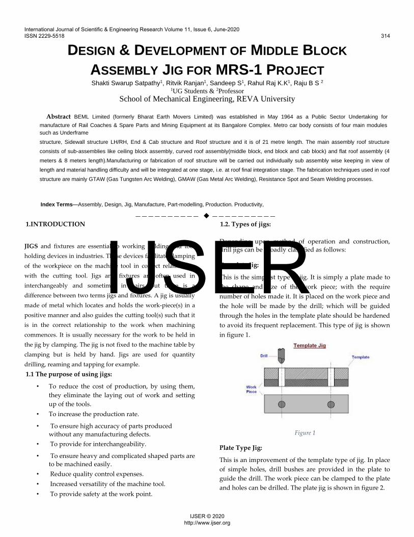
drill jigs can be broadly classified as follows: Template Jig: This is the simplest type of jig. It is simply a plate made to
the shape and size of the work piece; with the require
number of holes made it. It is placed on the work piece and
the hole will be made by the drill; which will be guided
through the holes in the template plate should be hardened
to avoid its frequent replacement. This type of jig is shown
in figure 1.
Figure 1 Plate Type Jig: This is an improvement of the template type of jig. In place
of simple holes, drill bushes are provided in the plate to
guide the drill. The work piece can be clamped to the plate
and holes can be drilled. The plate jig is shown in figure 2.
International Journal of Scientific & Engineering Research Volume 11, Issue 6, June-2020 ISSN 2229-5518 314
IJSER © 2020 http://www.ijser.org
IJSER

Figure 2
Channel jig: The channel jig is a simple type of jig having channel like
cross section. The component is fitted within the channel is
located and clamped by locating the knob. The tool is
guided through the drill bush. It is shown in figure 3.
Figure 3
Leaf Jig: It is also a sort of open type jig, in which the top plate is
arrange to swing about a fulcrum point, so that it is completely
clears the jig for easy loading and unloading of the work piece.
The drill bushes are fitted into the plates, which is also known
as leaf. The leaf jig is shown in figure 4.
Figure 4
1.3. Advantages of Jigs:
reduced due to increase in speed, feed and depth of cut because of high clamping rigidity.
• Interchangeability and quality:
Jigs and fixtures facilitate the production of articles
in large quantities with high degree of accuracy,
uniform quality and interchangeability at a
competitive cost.
• Skill reduction:
There is no need for skillful setting of work on tool.
Jigs make possible to employ unskilled or semi-
skilled machine operator to make savings in labour
cost. • Cost reduction:
Higher production, reduction in scrap, easy
assembly and savings in labour cost results in
ultimate reduction in unit cost.
1.4. Applications for jigs and fixtures: Typically, the jigs and fixtures found in a machine shop are
for machining operations. Other operations, however, such
as assembly, inspection, testing, and layout, are also areas
where work holding devices are well suited. There are
many distinct variations within each general classification,
and many work holders are actually combinations of two or
more of the classifications shown.
2.Review Stage The design and development of the jig is done in various
different stages. The process begins with thoroughly
understanding the complete manufacturing process of the
roof section. The manufacturing processes are taken into
consideration while designing the jigs. The part for which
the jig is to be built is then designed on a modelling
software. Catia V5, Solid Edge 2020, Autodesk student are
some of the softwares used in obtaining the 2D and 3D
models. We first produce a model of the roof section and
then design the jig based on the roof section designs.
• Productivity: Jigs increase the productivity by
eliminating the individual marking, positioning
and frequent checking. The operation time is also
International Journal of Scientific & Engineering Research Volume 11, Issue 6, June-2020 ISSN 2229-5518 315
IJSER © 2020 http://www.ijser.org
IJSER

2.1. Study of manufacturing process of middle
block of roof section
The manufacturing process of the middle block of
the roof section generally comprises of 8 different
parts which serve a unique purpose in the design
of the roof in order to hold all the additional
components rigidly. These components are
obtained based on the designs obtained from the R
and D department according to the customers’
demands, which in this case, is the Mumbai Metro
Rail Corporation. These parts are manufactured
individually on different work stations and
assembled together using the most common, spot
welding for enhances strength and toughness.
During these processes, usually there are errors
which vary the overall structure from the design
drawings. These errors and corrections are studied
deeply in order to obtain an economical and
sustainable “error free” production.
2.2. Design and analysis
The R&D department uses CATIA in order to obtain
the virtual image or a 3D image of the part to be
manufactured. These parts can be later assembled
virtually on CATIA. The behavior and compatibility
with the other components can be checked and
desired corrections can be made before actually
manufacturing the components. Hence, we produce a
virtual 3D image of the components which are being
manufactured in the company based on the
dimensions obtained during the study mentioned
above. It helps us obtain a clear picture of how the
middle block responds when it is processed after
placing it on a jig during the assembly. These parts
created in the CATIA software are then assembled.
The errors are then identified and necessary
rectification is done. The above created middle block
of the roof section is then analysed on a suitable
platform for any deformations on the assembly which
is under stress beyond the permissible limits. The
component is also subjected to a lot of heat during
various welding operations further in the line of
manufacturing. This creates heat affected zones which
affects these components
and are most likely to cause deformation in the
component which can affect the shape and
dimensional accuracy of the manufactured
component which could potentially harm the
overall strength of the component. These
deformations can be reduced if an appropriate and
a precise jig is used. The jig needs to arrest the
motion of the component placed on it in all
possible directions.
2.3. Final Stage Design of jigs for the suitable requirements
Jigs are mechanical devices that are used to hold the
component in its place by restricting all the degrees of
freedom in order to fix the component rigidly so that
the welding and other manufacturing processes can
be performed smoothly. As per the data collected
from the existing jigs used for manufacturing; it has
been identified that after the clamps used for the
welding processes are removed there is a change in
the dimensions beyond the tolerance limits due to a
phenomenon of SPRINGBACK EFFECT. Also, we can
see a considerable amount of weld distortions in
several places because of the heat produced by
welding. Keeping all these parameters in mind, we
have designed a jig structure which can significantly
reduce the distortions and the spring back effect.
Components of New Design Several parts/components were used in producing
3D model of the middle block of the roof section.
The parts used and their details have been
mentioned below:
Table 1
International Journal of Scientific & Engineering Research Volume 11, Issue 6, June-2020 ISSN 2229-5518 316
IJSER © 2020 http://www.ijser.org
IJSER

CANTRAIL
It is a piece of metal supporting the roof of a metro
carriage. The objective is to optimise resistance to
shocks, the cantrail/chassis is carried out by both
bolting and adhesive bonding. The old cantrail on
the fitting side of the coach has been cut in two
places to create three shorter sections. The
reinforcement part is a forged aluminium
component which is bolted to the cantrail. A 3D
model of a cantrail is shown in figure 5.
Figure 5
PURLINE
In steel construction, the term purline typically
refers to roof framing members that support the
roof decking or sheeting Purlines are most
commonly used in Metal Building Systems, where
Z-shapes are utilized in a manner that allows
flexural continuity between spans. (model shown
in figure 6)
Figure 6
CARLINE
The Carline is an arc shaped structure that supports
the roof structure of the middle block. The carline is
welded to the cantrail. There are two types of carlines.
one is the carline on the two ends of the middle block.
The carlines on either side of the middle block are
mirror images of each other. The other type of carline
is placed between the 2 ends. The part model of the
cantrail is shown in figure 7.
Figure 7
These parts are then assembled. The assembly is obtained on Solid Edge 2020/CATIA.
3.DESIGN OF THE JIG DEVELOPED
Left and Right purline locators Purline Locators can be found on both the sides of the middle
block which essentially hold the purline components in place
on either side of the middle block based on the dimensions
obtained in the drawing, just before welding the purline to the
carline structure. Purline locators also hold an additional
purpose by providing an ac exit vent structure on the roof
section. This structure of the locator is also an angled cut out
measuring 60mm height and 60mm breadth with a cut out of
50mm with a depth of 15mm from the top end at an angle of 99
degrees, as shown in figure 8 and 9.
International Journal of Scientific & Engineering Research Volume 11, Issue 6, June-2020 ISSN 2229-5518 317
IJSER © 2020 http://www.ijser.org
IJSER

Figure 8
Figure 9
Carline section The carline middle section is the one which comes right
next to the carline end jig. It acts as a guide way to place the
carline component accurately as per the dimensions. It does
not support the component while welding but only acts as a
channel to place the carline and making sure it connects to
both the cantrails.(part model shown in figure 10)
Figure 10
Carline end Locator (clamping) The carline end jig or the clamper is one of the primary
components of the entire middle block jig. This component
holds the carline rail with the help of mechanical clamps
and is used to hold the entire assembly rigidly by securing
and constraining all the degrees of freedom so that the
welding process can be done efficiently, based on the
required dimensions. One V shaped metal welded to a semi
triangular structure, which in turn acts as a guide way for
the cantrail and to clamp the carline to the cantrail
respectively. The model of this is as shown in figure 11.
Figure 11
The above part models are then assembled on a
workbench/table. On placing these locators in the
predetermined positions, we obtain the following Jig
Design. (as shown in figure 12)
Figure 12
International Journal of Scientific & Engineering Research Volume 11, Issue 6, June-2020 ISSN 2229-5518 318
IJSER © 2020 http://www.ijser.org
IJSER

3.1. Evaluating the effect of the newly designed jig on the
middle block of the roof section A new design cannot be approved by the industry for any
further operations unless it is tested and validated by the
firm that it serves the purpose rightly. Hence, this new
designed jig structure is to be tested in the manufacturing
process of the middle block of the roof section, by reducing
or eliminating the heat distortions which occur when the
component is subjected to high temperatures during
welding. The new jig is able to reduce the distortions and
the Spring back effect, the effective usage of the new jig
structure can take place in order to provide a comparatively
accurate and precise middle block section after the
operations performed during the assembly.
ACKNOWLEDGEMENT We use this opportunity to express our gratitude to all those
who have either directly or indirectly rendered us support in
our work. We feel fortunate and honoured to have Dr. Raju
B.S, Professor and Special Office, School of Mechanical Engineering, REVA University, who has been a constant
source of inspiration for us. His valuable suggestions and
also his interest in our work served as an impetus to us. We
would also like to thank BEML for providing us with the
platform to carry out our project and complete support
throughout the project. We would also like to thank Dr.
Sankar Reddy, Production Manager, BEML Ltd. for helping
us understand the production process and extended
support through the project duration.
Results The jig was tested in the assembly of 5 middle blocks. By
incorporating the new dedicated jig for fabrication of roof
middle block assembly the followings are the main
achievements of this project are summarised as below:
• The Length of the Middle Block Achieved= 5562 mm • Width of the Middle Block Achieved = 2534.6 mm • Height of the Middle Block Achieved = 415 mm • Diagonal of the Middle Block Achieved = 6112 mm • No. Of Spot welding’s missing = Zero
Conclusion As a result of the above work, by developing a jig in
accordance to the drawings, a higher dimensional accuracy
is obtained. Important factors like spring back effect during
the fabrication process, minimisation of welding
distortions, achieving good dimensional accuracy are
obtained by providing locators and supports very precisely
as per the drawing dimensions. Productivity is improved
due to reduction in cycle time and improvement in quality
of the middle block. The welding distortion is also found to
have significantly lowered. There is a reduction in
dimensional error due to Springback. The values obtained
for the dimensions of the middle block were closer to the
desired value. References [1] J. V. Kumbhar, H. C. Pandit, “A Review Article on Jigs
and Fixtures”, IJSR 2005 [2] R. D. Bhosale, S. S Nalawada, P. Swami, P. Gaikwad,
“Study of Jigs and Fixtures for base frame of Canopy
Fabrication of Generator”, IRJET May-2017 [3] H Radhwan, M S M Effendi, M. F. Rosli, Z. Shayfull, K.
N. Naida, “Design and Analysis of Jigs and Fixtures for
Manufacturing Process”, IOP Publication 2019 [4] R. Chabbra, P. Badhel, R. Pandey, Z. Mohammed, V.
Bhaiswar, “Review on Jigs and Fixtures”, IJSRD 2017 [5] S. N. Shindi, Siddhartkshirsagar, Riteshlomte, “Fixture
Design for Rooftop of Metro, Global Journals”, 2015 [6] Charles Okpala, Ezeanyim C., “The Design and Need
for Jigs and Fixtures in Manufacturing, Science
Publication”, July 2015 [7] S. Prabhakar S, BG Shivaji, SN Nagesh Mahadev, Lad
Atul Ajinath, “Multipurpose Jif & Fixtures”, IJSRD 2017 [8] Need for Jig and Fixtures in Manufacturing by Jatoth
Ramachander, ICRTESM-17 [9]Aditya A Yadav, Akshay Arekar, Yogesh Rajendra
Ghodake, “Design and Fabrication of Turning and Drilling
Jig for Exhaust Manifold”, IJTSRD [10] Amosh Shanker, Hemant Gurung, Laden Doma Bhutia,
T. Y. Ladhaki, “Design and Analysis of Linear Two Axis
Drill Jigs”, IJTARME
International Journal of Scientific & Engineering Research Volume 11, Issue 6, June-2020 ISSN 2229-5518 319
IJSER © 2020 http://www.ijser.org
IJSER

International Journal of Scientific & Engineering Research Volume 11, Issue 6, June-2020 ISSN 2229-5518 320
IJSER © 2020 http://www.ijser.org
IJSER