design against cracking at openings in prestressed ... journal/1995/nov-dec... · design against...
TRANSCRIPT

Design Against Crackingat Openings in PrestressedConcrete Beams
Hany Abdalla, Ph.D.Post-Doctoral FellowDepartment of Civil andEnvironmental EngineeringUniversity of WindsorWindsor, Ontario, Canada
Web openings in beams occur quite often in practice toprovide convenient passage of electrical and mechanicalconduits. In this paper, the analysis and design againstcracking of simply supported prestressed concrete beamswith rectangular openings are presented. Several designparameters are varied, including opening width and depth,horizontal and vertical locations of the opening, type of crosssection, and amount and arrangement of reinforcementaround the opening. The results from a finite element analysisare substantiated by test results. A simple design method forestimating the cracking load for the different crack patterns isproposed and two illustrative design examples are presented.
LJohn B. KennedyD.Sc., Ph.D, P.Eng.University Distinguished ProfessorDepartment of Civil andEnvironmental EngineeringUniversity of WindsorWindsor, Ontario, Canada
In modern building construction,openings through beams and girders are required for the passage of
utility ducts. Passing these ductsthrough openings in the webs of thefloor beams eliminates a significantamount of dead space and results in amore compact and, often, more economical design. However, the presence of openings gives rise to excessive stresses that may be detrimentalunless properly assessed and designed.Practical and experimental experiences have shown that, quite frequently, horizontal cracks develop atopenings at the transfer stage and inclined cracks develop at the corners ofopenings at the working stage. Suchcracks can seriously reduce the loadcarrying capacity of the beam.
Several investigations have beencarried out on reinforced concretebeams with openings (Mansur et al.”2).Comparatively little attention has beendirected toward the behavior of prestressed beams with openings. Barneyet al.3 suggested that the shear force atan opening in a pretensioned prestressed beam be distributed to thebottom and top chords of the openingin proportion to their uncracked moments of inertia until cracking occurs.After cracking, the shear distributionbetween the opening chords was basedon the extent of cracking in the tensionchord. Dinakaran and Sastry4proposedthat this force be distributed in proportion to the cross-sectional areas inpost-tensioned prestressed concrete Tbeams with openings.
60 PCI JOURNAL

More recently, Kennedy and Abdalla5 suggested a root ratio for distributing the shear force between thetop and bottom chords. However, noneof these investigations dealt specifically with the analysis or the designfor the potentially splitting tensionforces that develop at the edges of theopenings at the transfer stage and atthe corners of the openings at theworking stage. Kennedy and ElLaithy6 have investigated these forcesat the transfer stage for post-tensionedprestressed beams with rectangularsections.
It should be noted that the design ofprestressed concrete beams with openings is more complicated than the design of beams in reinforced concreteconstruction. In the latter case, theopenings are usually provided in thezone below the neutral axis where theconcrete is assumed cracked and,therefore, flexurally inactive. In prestressed concrete construction, though,the whole cross section is fully utilized and, hence, the presence of anopening will reduce the cracking loadcapacity of such beams.
In this paper, analytical proceduresare developed to predict and designagainst the several types of crackingthat are likely to occur in simplysupported prestressed concrete beamswith rectangular openings. The effectof the amount and arrangement of thereinforcement at different locationsaround the opening is studied. Resultsfrom a nonlinear finite element analysis are substantiated by an experimental investigation on several prestressedconcrete rectangular T- and I-beams.
THEORETICAL ANALYSISThe theoretical study was based on
the nonlinear finite element programABAQUS (Hibbitt et al.7). The following design parameters were considered:
1. Horizontal and vertical locationsof the opening
2. Opening width and depth3. Type of cross sectionA rectangular plane stress element
was used to analyze beams of rectangular cross sections. For beams of Tsections and I-sections, the same rectangular plane stress element wasutilized to model the web, whereas the
flange(s) was modeled by a four-nodeplate element with six degrees of freedom. A parametric study was carriedout to determine the effect of the reinforcement against the different typesof cracks around the opening. Reinforcing bars were placed at differentlocations around the opening with various cross-sectional areas and arrangements. The direction of the reinforcement, whether horizontal, vertical, orinclined, was also studied.
In the nonlinear analysis, the load isapplied gradually in small incrementsas defined in the ABAQUS program.The size of each increment depends onthe convergence of the iteration process in the previous increments. Theconcrete under compression is modeled by an elastic-plastic theory, usinga simple form for the yield surface expressed in terms of the equivalentpressure stress and the Mises equivalent deviatoric stress (Hibbitt et al.7).Isotropic hardening is also accountedfor. Cracking is assumed to occurwhen the stress reaches the failure sur
b=102 mm
tf=51 mm13=458 mmH=357 mm
face represented by a simple Coulombline in terms of the equivalent pressure, p, and the Mises equivalent deviatoric stress, q (Hibbitt et al.7).
The model is a smeared crackmodel, in the sense that it does nottrack individual macro cracks. Instead,constitutive calculations are performedindependently at each integrationpoint of the finite element model andthe presence of cracks enters intothese calculations by the way in whichthe cracks affect the stresses and material stiffness associated with the integration point. The cracking and compression responses of the concrete aswell as the influence of tension stiffening due to the presence of the reinforcing steel are given elsewhere(Kennedy and Abdalla).
The concrete model in ABAQUS isdesigned to provide a general methodfor modeling reinforced and prestressed concrete. The program provides a REBAR option to model thereinforcing bars. Reinforcing bars areone-dimensional strain theory ele
IIIx
J- w___
_______
3.OmL__ W .
mma-J
[
hr
Hh: H
Lhb Ch
F h3
Hh
hbj
b=102
H=254
_—_ B
b=102 mmtf=51 mm13=458 mmH=305 mm
mm
mm
Section X—X
Fig. 1. Layout of tested beams.
Note: 1 in. 25.4 mm
November-December 1995 61

K K K Xl K - K XXIX
K1524mm *
Fig. 2. Reinforcement details for: (a) rectangular beam; (b) T-beam; (c) I-beam; and (d) tested I-beam BITI1A.
ConcreteEccentricity and compressive
Dimensions of opening Location of opening prestressing force strength
Beam W h 1 C e F fidentification (mm) (mm) (m) (mm) (mm) (kN) (MPa)
Rectangular
BI1A 305 76 1.00 127 36 149 41
BI1B,BI3A 305 76 0.86 127 40 139 43
BI2A 406 76 0.81 152 46 118 50
BI2B,BI3B 406 76 0.81 127 48 141 43
BI2C 406 76 0.81 102 47 116 45
BI3C 508 76 0.76 127 45 116 42
T-beams
BII1A 457 102 0.84 165 85 194 44
457 102 0.69 165 82 171 54
BII1C 457 102 0.53 165 80 180 53
BII2B 457 102 0.69 127 84 173 48
BII4C 457 127 0.69 165 71 189 50
I-beams
B1I11A 457 127 0.69 178 62 294 47
BIII1C 457 127 0.46 178 55 270 41
rf—2—4.8 mm barsI 89Jl2—4.8 mm bars
254 t E]—4,8 mm stirrupsmml 76[j—26.4mm barsII ii 2—6 4 mm bars
prestressing wires102 mm
(a)
457 mm• ,457mm
K
r448 mm bars
mm bars
.8 mm stirrups
2—6.4 mm bars.2—64 mm barsprestressing wires
102mm
(b)
prestressing wires—
mm bars
2—6.4 mm bars
4.8 mm stirrups
mm bars
-6—6.4 mm barsprestressing wires
cc)
4.,,102x356x19 mm
steel bearing plute
160 mm
140 140 25 152 152 152 25102 254
—-‘ mm32 mm
(d)
254 51 25 mm
Note: 1 in.=25.4 mm
Lable 1. Characteristics of tested beams.
Note: 1 in. = 25.4 mm; 1 kip = 4.45 kN; I ksi = 6.89 MPa.
62 PCI JOURNAL

ments that are used with standardmetal plasticity models to describe thebehavior of the reinforcing bar material, and are superimposed on a meshof standard element types usedto model the plain concrete. Effectsassociated with the reinforcing bar!concrete interface, such as bond slipand dowel action, are modeled by introducing tension stiffening to simulate load transfer across cracksthrough the reinforcing bar.
Three types of cross sections wereanalyzed: a rectangular section, a Tsection, and an I-section, denoted asBI, BIT, and Bill, respectively. Eachcross section was divided into groupsaccounting for changes in one of theparameters mentioned earlier. The parameters, horizontal location, verticallocation, opening width, and openingdepth, were assigned the numbers 1, 2,3, and 4, respectively. For example,Group B112 is for T-beams where thevaried parameter is the vertical location of the opening.
EXPERIMENTAL STUDYThe objectives of the experimental
investigation were to determine:1. The crack propagation pattern
due to the prestressing force and dueto the vertically applied load
2. The strain distribution in thevicinity of the opening
3. The deflection at the transfer andservice load stages
Tests were carried out on 13 post-tensioned prestressed concrete beams:six of the beams were rectangular insection, five were of T-section and theremaining two were of I-section. Thelayout of the tested beams is shown inFig. 1. The concrete was designed fora 7-day compressive strength of 41MPa (6000 psi). The percentage offine aggregate to total aggregate was48 percent. The water-cement ratiowas 0.4 with an aggregate-cementratio of 2.7, both by weight. Highearly strength portland cement wasused and the maximum size of coarseaggregate was 10 mm (/8 in.). Hightensile wires, each 7 mm (0.276 in.) indiameter with an ultimate nominalstrength of 1760 MPa (255 ksi), wereused for prestressing.
Stirrups of mild steel wire of 300
MPa (44 ksi) nominal yield strength,5 mm (0.2 in.) in diameter, were provided. It was decided to use the minimum ratio of shear reinforcement inthe top and bottom chords of the opening following the ACT Code.8 The reason for this decision was to examinethe shear strength of the chords withminimum shear reinforcement, as suggested earlier by Barney et al.3
The end bearing plates were 102 x254 x 20 mm (4 x 10 x 3/4 in.) thick forrectangular beams, 102 x 305 x 20 mm(4 x 12 x 3/4 in.) thick for T-beams, and102x356x20mm(4x 14x3/4in.)thick for I-beams. Plastic tubes 11 mm(/16 in.) in diameter housed the prestressing wires during casting of theconcrete. Typical reinforcement details for the tested beams are shown inFig. 2. Linear strain gauges were installed in the region of the opening.
Mechanical dial gauges with a travelsensitivity of 0.025 mm (0.001 in.)were used to measure the camber anddeflection profile of the beam duringprestressing and during the applicationof the external vertical loading. A hydraulic jack of 89 kN (20 kips) capacity was used for the post-tensioningoperation, which involved the use ofwashers and open type grips consisting of an exterior cylinder and a splitconical interior wedge. Details of the
thirteen beams tested are shown inTable 1.
RESULTSResults from the nonlinear finite el
ement analysis were compared tothose from the tests on the thirteenprestressed concrete beams as well asto those from tests carried out byKennedy and El-Laithy.6The stressand strain distributions around theopening were determined at the transfer stage, where the beam is subjectedto the prestressing force only, and atthe service load stage, where the prestressed beam is subjected to a vertical load just below the cracking load.This load was 18 kN (4 kips) for therectangular Beam BT2C, shown inFig. 5, according to the experimentalobservations.
The influence of the opening on deflection, stresses, and crackiiig was examined. The effect of the amount andarrangement of reinforcement aroundthe opening was also studied.
The experimental results revealedfive critical locations for potentialcracking of prestressed beams withopenings, as shown in Fig. 3. Thoselocations are: (1) at the edges of theopening due to the prestressing force;(2) at the corners of the opening due to
(1) Cracking at Transfer(2) Cracking of the Opening Corners (Service Load Stage)(3) Cracking at the Edges of the Opening (Service Load Stage)(4) Cracking of the Tension Chord (Service Load Stge)(5) Shar. Cracking (Service Load Stage) s
Fig. 3. Different types of cracking around opening.
November-December 1995 63

Fig. 4. Crack patterns for prestressed concrete beams with openings.
the framing action at the opening region; (3) in the opening chords due tothe flexural stresses resulting from thesecondary moments in these chords;(4) in the tension chord due to the normal tensile stresses in that chord; and(5) in the opening chords due to shear.
The first of the five types of potential cracking occurs at the transferstage due to the prestressing forceonly, while the other four types occurat the service load stage. It should benoted that the last two types of cracking can trigger the complete collapseof the beam.
It should also be mentioned that,whether the beam is post-tensioned orpretensioned, both types are designedherein to include mild steel bonded reinforcement around the opening. As far asthe mild steel reinforcing around theopening is concerned, the structural response of both post-tensioned and
bonded pretensioned precast beams willbe similar at transfer as well as at the service load stage prior to initial cracking.
At the service load stage and for thepurpose of estimating the load causingcracking around the opening, the proposed methods of analysis herein canbe applied to unbonded and bondedpost-tensioned beams as well as topretensioned precast beams (Lin andBurns9). This is because the non-prestressed longitudinal reinforcement inthe opening chords and the verticalstirrups around the opening providethe required resistance against localcracking at the opening. The prestressing steel, whether bonded or not, resists the flexural cracking at the beammidspan. It should also be noted thatthe buckling of the compression chordat the opening is not addressed hereinbecause it was discussed in detail elsewhere (Abdalla and Kennedy’°).
Cracking at Openings Dueto Prestressing Force(Transfer Stage)
The prestressing force gives rise tovertical splitting tensile stresses at theopening edges causing horizontalcracks, as shown in Fig. 4(a). Themaximum value of these stresses occurs very close to the mid-depth of theopening, regardless of the position ofthe opening or the position of the prestressing force, as shown in Fig. 5(a).Furthermore, even in T-beams, wherethe top and bottom chords are differentin shape, results show that the maximum vertical tensile stress occurs veryclose to the middle of the opening.
The results also reveal that as theopening is moved vertically towardthe horizontal line of action of the prestressing force, the maximum verticalsplitting stress increases. The horizon-
1[’L_
.
L:IJo
64 PCI JOURNAL

For a rectangular section:
Theoretical
— — —— Experimental
P=0.0 kN
Note: 1 kip 4.45 kN
1 ksi = 6.89 MPa
F;—F1+F2+F3 (4)
It is assumed that the force F; is resisted by internal forces F; and F;, inthe top and bottom chords of the opening and that the diffusion of the force
F; is through the skeletal truss ABC, asshown in Fig. 6. It can be shown (ElLaithy” and Kennedy and E1-Laithy6)that the vertical splitting tensile force,T, can be estimated as:
Ta(y - a)
F (5)frY
wherehba=y—e——2
/3 = d + d
y=h++3 2 (6)
d=l3—hC
d =3h
in whichFig. 5. Vertical stress distribution at the opening: (a) transfer stage; h = depth of opening(b) service load stage. h, = depth of top chord
hb = depth of bottom chordtal location of the opening and the third are the fractions of F1 and F2, H = depth of beamwidth of the opening have a minor ef- whose diffusions into the web are in- C distance from center of openingfect on the splitting stresses at the terrupted by the presence of the web to bottom edge of beamopening edges at the transfer stage. opening. Thus, it can be shown that [The numerical coefficient 13 in d is aHowever, increasing the depth of the (Abdalla”): dimensional constant in mm (Kennedyopening significantly increases the and El-Laithy6).1
For design purposes, the verticalmaximum splitting stress at mid-depth 1+ + F; tensile stress distribution can be as-of the opening at the transfer stage. A — Af ,J A — A, J sumed to be triangular. Thus, the max-Kennedy and El-Laithy6and Kennedy
et al.” examined the relationship be- (1) imum vertical tensile stress, f, due totween the prestressing force and the in which A, Af,, Af2, and A are the
the prestressing force can be calculated as:vertical splitting stress at mid-depth of areas of the web, bottom flange, top
the opening. As shown in Fig. 5(a), flange, and total cross section, respec- = 21f (7)the value of this stress is also high at tively. The eccentricity of F, from the dbthe corners of the opening. It is this center of gravity of the cross section,
stress at the corners of the opening e, can be determined from statics as: Adding vertical non-prestressed rethat, when added to that due to the ap- inforcement at the edges of the open-plied vertical load, causes cracking at
e + F;e3ing increases the prestressing force
the corners of the opening. e F needed to cause cracking at the open-Fig. 6 shows the free-body diagram = [ ‘[A — Af, ing edges, as shown in Fig. 7. From
for an I-beam with a rectangular open- the results, it can be observed thating and subjected to applied prestress- Fl’ A ‘1e2]iF; (2)
adding one closed stirrup 5 mm (0.2 in.)ing forces F,, F2, and F3. The compo- A_Af} in diameter increases the requirednent of the prestressing force causing cracking prestressing force by aboutthe vertical tensile force at the open- For a T-section: 17 percent.ing, F;, is composed of three parts: one Increasing the amount of this vertiis the prestressing force F3, applied di-
F;=
(.4-) + J (3)cal reinforcement increases the pre
rectly to the web; the second and the stressing force, causing cracking, and
November-December 1995 65

Fig. 6. Development of vertical tensile force at an opening.
should be arranged within the distanced and be placed as close as possible tothe opening edge.
If cracking is allowed at the transferstage, then stirrups can be designed toresist the total splitting tensile force.Because the splitting stress has a steepgradient, it is recommended that thedesign stress for the reinforcing steelbe taken as one-half the allowablestress,f. Thus:
A=- (9)
Such reinforcement should be arranged as closed stirrups, also withinthe distance d, from the opening edge.
Considering the vertical tensilestress at mid-depth of the opening atthe transfer stage to be equal to f, themaximum value of the tensile stress,
f, at the four corners of the openingdue to the prestressing force only canbe estimated assuming a linear distribution, as shown in Fig. 8. Thus:
f=[f (10)
for hb h,
or
( h—t
H_c_tjJ(11)
for h hb
Using Eq. (7) and substituting:
2T
d1b
in Eqs. (10) and (11), the maximumtensile force at the four corners of theopening can be estimated as:
(hb—t lI (12)
C- t j
for h,, h
or
( h—iT=I IT (13)
H—C—tf)
for Ji hb
This force Tf will be added to theforce due to the vertical load in orderto determine the total reinforcementrequired at the opening edges, as will
Fig. 7. Effect of vertical reinforcement on the prestressing force causing crackingat the opening edges.
decreases the rate of increase in thatforce. However, there is a certain optimum percentage of vertical reinforcement beyond which no significant increase in this prestressing forceoccurs. From the finite element parametric study, it was determined thatbefore cracking, the concrete and thereinforcement both resist the verticalsplitting tensile force according to themodular ratio, n. It was found that thetotal resisting tensile force, T, can beexpressed as follows:
i =)()+t’[(nl)A]jc1
(8)
where
A = cross-sectional area of closedstirrups at one edge of opening
= length of tension field at opening edge, determined by Eq. (6)
b = beam widthd’ = distance between opening edge
and center of gravity of steel areauniformly disthbuted within distance d, and equal to 0.5d
f = direct tensile strength of concrete, 0.33,/ MPa (4.0fpsi) (Collins and Mitchell’4)
It can be observed from Eq. (8) thatthe splitting tensile stress was assumedto have a triangular distribution. Thisassumption was verified by the test results. Havingj determined from aboveand equating the splitting tensile force,T, calculated from Eq. (5) with Tr inEq.(8), the area of vertical stirrups, A4,required to resist the splitting stress atthe transfer stage can be estimated. Itshould be noted that these stirrups
PCI JOURNAL

Fig. 9. Shear stress distribution at opening(b) service load stage.
be discussed later. It should be notedthat Eqs. (12) and (13) were developedfor I-sections. However, they can alsobe applied to other sections by puttingtf = 0 in both equations for rectangularbeams and tf = 0 in Eq. (12) for Tbeams.
Fig. 9(a) shows the shear stress distribution around the opening at thetransfer stage. It can be seen from theresults that the prestressing force induces significant shear stresses at the
at: (a) transfer stage;
opening corners and insignificantstresses at the chords of the opening.While the horizontal location of theopening and the width of the openinghave almost no effect on the shearstresses at the transfer stage, the vertical location and depth of the openingsignificantly affect these stresses. Asthe opening is moved vertically toward the line of action of the prestressing force or as the depth of theopening increases, the shear stresses
around the opening increase.Considering the camber of the beam
due to the prestressing force, the dimensions and the location of the opening were found to be the main factorsaffecting the maximum camber at thecenter of the beam. The vertical reinforcement at the opening edges wasfound to have no effect on the camberof the beam at this stage of loading.
Cracking at OpeningDue to Vertical Load(Service Load Stage)
At the service load stage, the beamis subjected to a vertically appliedload as well as the prestressing force.For such loadings, different types ofcracks can develop around the opening, as shown in Figs. 3 and 4.
Cracking at the Opening Corners— Based on the finite element analysis substantiated by the test results, itwas found that, due to the applicationof an external vertical load, the maximum splitting tensile stress shifts upward at the right edge of the openingand downward at the left edge of theopening, as shown in Fig. 5(b). Thiscan cause cracking of the openingcorners, as shown in Fig. 4(b).
The cracks at these corners are dueto the splitting stress, f1f. resultingfrom the prestressing force as well asto the splitting stress, J,, resultingfrom the external vertical load. Because the tensile force generated fromthe combination of ftf andf, is almostvertical, vertical reinforcing steel becomes more effective than inclined reinforcing steel in controlling cornercracking in prestressed beams withopenings. This is unlike reinforcedconcrete beams where the resultantforce is inclined more to the longitudinal, in which case inclined reinforcing steel is more effective than vertical reinforcing steel.
The stress, ff1,, due to the verticalload was found to have a distributionalong a horizontal plane passing byCorner 3 in Fig. 10(a), changing fromtension to compression in a distanced, as shown in Fig. 10(b). At Corner2, f changes from compression totension in the same distance d, asshown in Fig. 10(c). It can be seenthat similar stress distributions occur
(a) hb h
(b) h1 hb
Fig. 8. Vertical tensile stresses at opening.
P=0.0 kN
=ll3 kN
(a)
=113 kN
Note; 1 kip = 4.45 kN
1 ksi = 6.89 MPa
November-December 1995 67

at Corners 1 and 4, respectively.The horizontal location of the open
ing has a minor effect on thesestresses, while the vertical location ofthe opening significantly affects thesestresses. The maximum splitting stressat the service load stage occurs at theopening corner corresponding to the
IF
(a)t
(L ‘cv
d0K
• (b) (C)
Rg. 10. Vertical tensile stresses at opening.
,s.
j:iMsb
are transferred to the solid segments atthe opening edges, as shown in Fig. 11.
Because the deeper chord carries alarger amount of shear, it is subjectedto higher splitting stresses. Increasingthe width of the opening increases thesecondary moment at the openingedges and results in higher verticalsplitting stresses at the opening corners. Increasing the depth of the opening significantly increases the verticalsplitting stress at the upper right andthe lower left corners of the opening.
From the above discussion, it can beassumed that there is a segment of thebeam at each end of the opening contributing a framing action to the opening chords shown in Fig. 11. The widthof these beam segments is (4 + dr), asshown in Fig. 11(a). A parametricstudy has shown that the values for 4and cI are almost the same as thosepreviously given in Eq. (6). It can alsobe assumed that at Corner 3 [Fig.10(a)], the moment transferred to Segment CB is resisted by two forces, Tand C, shown in Fig. 10(b), where Tis assumed to act at a distance 4/3from Corner 3 and C is assumed to actat the middle of the distance d. Thus,the tensile force 7 due to the verticalload can now be calculated from:
=
(14)
in which M5 is the secondary momentat the top chord of the opening. Assuming a triangular distribution for thevertical splitting stress, the maximumtensile stress can be calculated as:
(15)
This stress is due to the vertical loadonly. The vertical stresses due to prestressing at the corners should beadded to this stress to derive the totalvertical splitting stress at the openingcorner for design.
A parametric study was carried outto determine the effect of the amountand arrangement of reinforcement oncracking at the corners of prestressedbeams with openings. The area, number and direction of the reinforcingsteel, whether vertical or inclined, werestudied. Fig. 12(a) shows the effect of
It +
Mt
Msb
dt + d0[. ..1
-4
“Msb
Fig. 11. Framing action around opening.
deeper chord. This is because the splitting stress occurs due to a framing action between the opening chords andthe solid concrete segments at theedges of the opening. Through thisframing action, the secondary moments at the opening chords resultingfrom the shear forces at these chords
68 PCI JOURNAL

the area of vertical reinforcement onthe cracking load capacity. It can beobserved from the results in Fig. 12(a)that there is an optimum percentage ofreinforcing steel beyond which no increase in the above capacity will occur.This is because this capacity is also affected by other capacity reducing factors discussed below.
The arrangement of the vertical reinforcement at the edges of the opening was also examined. It was foundthat placing all the required reinforcement as close as possible to the opening edge instead of distributing this reinforcement over the distance d1increases the cracking load by 10 to 15percent. Therefore, it is recommendedthat all the vertical reinforcementshould be placed within a distance d1from the opening edge and as close aspossible to the opening edge.
The effectiveness of using inclinedreinforcement at the four corners ofthe opening in prestressed beams wasalso studied. It was found that placingthe reinforcement at an inclination of45 degrees increases the cracking loadby only 10 percent in comparison tousing vertical reinforcement. The bondlength of the vertical reinforcementshould be checked for adequacy. Thisbond can be improved by using morebranches of vertical closed stirrups.
To estimate the area of reinforcingsteel required to resist a certain vertical applied load, P, the Vierendeelmethod of analysis, described byKennedy and Abdalla,5 can be appliedto determine the secondary moments
and M$b at the top and bottomchords of the opening, respectively.The larger of the two moments M5 andMSb is used in Eq. (14) to determinethe tensile force T at the opening edgedue to the vertical load.
After replacing Tr with (T + Tf),where T and Tf are given by Eq. (14),and Eqs. (12) or (13), respectively,Eq. (8) is used to determine the required area of reinforcing steel to prevent cracking at the corners of theopening. This area of reinforcementshould be added to the reinforcementrequired to resist the shear stresses resulting from the external load on thebeam.
It should be noted that for beamswith T- or I-sections, cracking at the
opening corners may cause separationalong the interface between the flangeand the web of the section. Therefore,the reinforcing steel should extend wellinto the flange with adequate anchoragelength to resist such separation.
Cracking at the Edges of theOpening — Fig. 4(c) shows the thirdtype of cracking at the openings. This
cracking occurs as a result of the primary moment and the secondary moment in the opening chords. Thesemoments cause flexural tensilestresses at the upper left and the lowerright corners of the opening chords, asshown in Fig. 3.
The secondary moments in theopening chords are formed by the
z
0-
C)
0)
0 0,1 0.2 0.3 0.4 0.5
Percentage of Steel Area (A/bH)
Note: 1 kip = 4.45 kN
Fig. 12(b). Effect of reinforcement at opening chords on cracking load.
November-December 1995 69

AbW =
A =
‘b’ ‘t =
sisting of area of concrete Aand area of transformed steel(n — 1 )A of tension chord
By assuming an allowable flexuraltensile stress (ACI Code8), the area ofsteel A required to prevent crackingcan be estimated from Eq. (17). Itshould also be noted that the presenceof secondary moments at the openingedges may cause cracking in theflange even if it is in the compressionchord. The effect of reinforcing thetop and bottom chords using longitudinal bars in the two chords was studied.Fig. 12(b) shows that increasing thesteel area in the opening chords increases the cracking load of prestressed beams with openings.
Cracking of the Tension Chord —
Cracks start at the corners of the bottom chord due to the tensile stressesresulting from the combined effect ofthe primary moment and the secondary moments. For relatively shallow bottom chords, it was further observed that when the net axial stressesat the middle of the bottom chord exceed the allowable tensile stress of theconcrete, a crack will extend the fulldepth of the tensile chord, as shown inFigs. 3 and 4(d).
The condition for such cracking canbe represented by:
T=N—FbO.62Ag[7c (18)
shear forces in the chords. Therefore,it is important to accurately predict thedistribution of shear between the topand bottom chords of the opening.From the finite element parametricstudy substantiated by test results, itwas shown (Abdalla’2)that the shearforce carried by the bottom chord ofan opening in prestressed concretebeams can be determined from:
____
(16)V
- jAbWIb +ji
where
Vb = shear force carried by bottomchord
V = total shear force at center ofopeningb x hb = area of bottom webb x = area of top webmoments of inertia of bottomand top chords about their centroidal axes, respectively
It should be noted that Eq. (16) isvalid as long as the tension chord isnot cracked. Having determined theshear force distribution between thetop and bottom chords of the opening,the Vierendeel method given byKennedy and Abdalla5 can be appliedto determine the cracking load of theopening chords. In that method, themaximum tensile stress f in the tension chord is calculated as:
f— iNMSbyts
Ab Ab ‘b
Fb = prestressing force in bottomchord
N = tensile force resulting fromprimary moment and equalto MmIY in which Mm is theprimary moment at the center of the opening and Y isthe vertical distance between the centroids of theopening chords
MSb = secondary moment in bottom chord
y = distance from center ofgravity of bottom chord toupper extreme fiber of samechord
Ab, ‘b = area and moment of inertiaof transformed section con-
ultimate load capacity of the beam. Adifference of about 15 percent wasnoted between the two cases.
Shear Cracking — The prestressing force gives rise to shear stressesclose to the opening corners, whilethe applied vertical load producesshear stresses in the opening chords,as shown in Fig. 9. The vertical location of the opening and the openingdepth are the major factors affectingthe shear stresses around the openingat the working load stage beforecracking.
After cracking of the openingchords, the shear force carried by eachchord depends on the level of crackingof that chord. Before cracking, theratio of the shear force carried by eachchord is given by Eq. (16). Excessiveshear stresses in the opening chordsmay cause shear cracks similar tothose shown in Figs. 3 and 4(d). Toavoid such cracking of the openingchords, the shear stresses must not exceed the allowable shear stresses.
The effect of the axial forces,whether compression or tension, hasto be taken into consideration. Beforecracking, the shear force is distributedbetween the top and bottom chords according to the root ratio given by Eq.(16).
After cracking, the following simplified conservative procedure for estimating shear forces in the openingchords is presented: if the crack in thebottom chord extends the full depthand the tension force in the tensionchord is:
T 0.62Ab-f
then it is recommended that the compression chord carries the total shear:
Vt—V (20)Vb 0
If, on the other hand:
T 0.62Ab-s[jL
then the shear force in the tensilechord is calculated from Eq. (16) atcracking, i.e., Vbcr, with the compression chord carrying the remainingshear:
VVVbcr (21)
In this case, the shear force carried
where
where Fb is the prestressing force in
17the bottom chord and is calculated assuming a triangular stress distributionin the top chord of the opening at thetransfer stage. For the bottom chord, arectangular stress distribution can beassumed (Kennedy and Abdalla5).
To prevent this type of cracking,longitudinal reinforcement should beprovided in the tensile chord. Withsuch a provision, the resisting tensilestrength of the tension chord in thiscase becomes:
= 0.62.[.i’[A +(n — 1)A] (19)
Equating Tr to T, given by Eq. (18),the required area of steel A can be estimated. From the parametric study, itwas found that placing this reinforcement near the upper and lower fibersof the tension chord, rather than distributing the reinforcement uniformlyover the cross section, augments the
PCI JOURNAL

by the bottom chord can be calculatedfrom Eq. (16) for design purposes.The use of this simplified method fordetermining the shear forces in theopening chords results in a conservative design against shear failure in theopening chords.
The calculated shear forces shouldbe compared to the ultimate shear capacity, V, of a concrete section subjected to shear and prestressing forcesand given by the ACT Code8 as:
where
V (22)
0.l4Jb1,d
Mcr = cracking moment of openingchord, estimated using methodgiven by Kennedy and Abdalla5
f’ = concrete strength in MPaW opening width
b = width of webd = depth of opening chordIf the shear in either of the top or the
bottom chords exceeds V, given byEq. (22), vertical stirrups are requiredto resist the difference. In this case,the shear force carried by vertical stirrups is given by:
vs=vc-vci (23)
where V is the shear force in any ofthe opening chords and l’ is the shearforce carried by the concrete in thatchord.
The amount and arrangement of thevertical stirrups in the opening chordscan be determined by applying thewell known formula of = Afd/swhere A is the cross-sectional area ofthe vertical stirrups, d is the depth ofthe chord, s is the spacing betweenstirrups, and f is the yield strength ofthe reinforcing steel.
In order to validate the above proposed design procedure, it was applied to the tested beams. Table 2shows a comparison between the testand the analytical cracking loads ofthe tested beams. The analyticalcracking loads were estimated according to the proposed design equations.It can be observed from Table 2 thatthe test results are invariably higherthan the analytical values. The reasonfor this discrepancy is that the testcracking loads were recorded when
Table 2. Cracking loads of tested beams.
Note: 1 kip = 4.45 kN; 1 ksi = 6.89 MPa.
cracks were observed by the nakedeye and it is well known that hairlinecracks precede this stage. Notwithstanding, the results from the proposed design procedure are on theconservative side and, therefore, theprocedure will yield a conservativedesign.
DESIGN EXAMPLE 1A 9.2 m (30 ft) simply supported
post-tensioned prestressed concrete I-girder has been designed to resist atotal moment of 422 kN-m (310 kipft) due to a load P = 165 kN (37 kips)at midspan and due to its own weight,
= 4 kN/m (0.27 kip/ft). Six 15 mm(0.6 in.) steel strands with an ultimatetensile strength of 1725 MPa (250 ksi)were used for prestressing the 45 MPa(6.5 ksi) concrete. The effective prestressing was estimated at 620 kN(140 kips). One web opening 255 mm(10 in.) deep by 914 mm (36 in.)wide, shown in Fig. 13, was requiredfor the passage of utility services. Thecenter of the opening was to be located 3.05 m (10 ft) from the support.
Design the reinforcement requiredaround the opening to resist cracking.
Defining A, A11, Af2, and A as theareas of the web, bottom and topflanges, and the total cross section, respectively, then from Fig. 13:A = 0.088 m2 (137 sq in.)
A1 = Af2 = 0.043 m2 (68 sq in.)A=0.175m2(271 sq in.)The areas and moments of inertia of
the top and bottom chords of the opening are:A1 = 0.081 m2 (126 sq in.)
= 1.16 x 10 m4 (2778 in.4)Ab = 0.062 m2 (96 sq in.)
0.275 x 10 m4 (659 in.4)I 17.9x10³m4 (43,036 in.4)(the
moment of inertia of the crosssection at midspan)
Cracking Due toPrestressing Only
From Eqs. (1) and (2):F2=483kN(l09kips)e= 236 mm (9.3 in.)Using the geometries of the I-girder
shown in Fig. 13 in Eq. (6) gives thefollowing values:a = 94 mm (3.7 in.)/3 = 1010mm (39.8 in.)7=515mm (20.3 in.)
d1 = 112 mm (4.4 in.)d = 898 mm (35.4 in.).
From Eq. (5), T = 36.8 k.N (8.3 kips).The allowable direct tensile strength
= = 0.33-/ = 2.2 MPa(0.3 ksi). From Eq. (7), f1 = 5.2 MPa(0.8 ksi) > 2,2 MPa (0.3 ksi). Hence,vertical reinforcement is required. Substituting Tr = T2 = 36.8 kN (8.3 kips) inEq. (8) yields A2 = 3852 mm2 (6 sq in.)Use five #7, 2-branch stirrups within
-
Analyticalcracking load
(kN)
Concretestrength
f’(MPa)
ExperimentalBeam cracking load
identification (kN)
Rectangular
BI1A 20
BE1B 22
BI2A 18
BI2B 22
BI2C 22
BI3C 16
——
Prestressingforce
F(kN)
17
18
14
17
18
13
41
43
50
43
45
42
149
139
118
141
116
116
T-bearn
BI11A
Bill B
BIIIC
BII2B
BII4C
I-beains
BIIIIA
BIII1B
33
36
36
33
29
29
3033
31
26
44
54
53
48
50
194
171
180
173
189
53
49
47
45
47
41
294
270
November-December 1995 71
V430 mm
L/
A
K9200 mm
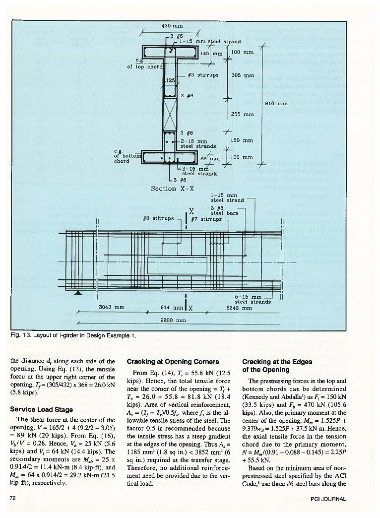
Fig. 13. Layout of I-girder in Design Example 1.
the distance d1 along each side of theopening. Using Eq. (13), the tensileforce at the upper right corner of theopening, 7}= (305/432) x 368 26.0 kN(5.8 kips).
Service Load StageThe shear force at the center of the
opening, V = 165/2 + 4 (9.2/2 — 3.05)= 89 kN (20 kips). From Eq. (16),Vb/V = 0.28. Hence, Vb 25 kN (5.6kips) and V = 64 lcN (14.4 ldps). Thesecondary moments are MSb = 25 x0.914/2 = 11.4 kN-m (8.4 kip-ft), andM35 = 64 x 0.9 14/2 = 29.2 kN-m (21.5kip-ft), respectively.
Cracking at Opening Corners
From Eq. (14), T8 = 55.8 kN (12.5kips). Hence, the total tensile forcenear the corner of the opening = +
T5 = 26.0 + 55.8 = 81.8 kN (18.4kips). Area of vertical reinforcement,A5 = (Tf + T)/0.5f5,where f5 is the allowable tensile stress of the steel. Thefactor 0.5 is recommended becausethe tensile stress has a steep gradientat the edges of the opening. Thus A5 =
1185 rmTi2 (1.8 sq in.) < 3852 iTim2 (6sq in.) required at the transfer stage.Therefore, no additional reinforcement need be provided due to the vertical load.
Cracking at the Edgesof the Opening
The prestressing forces in the top andbottom chords can be determined(Kennedy and Abdalla5)as F1 = 150 kN(33.5 kips) and F,, = 470 kN (105.6kips). Also, the primary moment at thecenter of the opening, Mm = 1 .525P +
9.379wd = 1.525P + 37.5 kN-m. Hence,the axial tensile force in the tensionchord due to the primary moment,N = Mm/(0.91 — 0.088 — 0.145) = 2.25P+55.5kN.
Based on the minimum area of nonprestressed steel specified by the ACTCode,8 use three #6 steel bars along the
I’ I’
of
strand
mm
#3 stirrups 305 mm
3 #6
255 mm
3 #6
-2—15 mmsteel strands
chord
/
910 mm
150 mm
100 mm
Section X—X
/
3043 mm 914 mmlx5—15 mmsteel strands
5243 mm
72 PCI JOURNAL

2400 mm 1’
Fig. 14. Layout of double tee in Design Example 2.
top as well as along the bottom chords.Taking into account this area of steel,the area and moment of inertia of thebottom chord are 0.07 m2 (108 sq in.)and 0.4 x 10 m4 (958 in.4). Using Eq.(17), the load P causing cracking inthat chord can be shown to be 175 kN(39.3 kips)> 165 kN (37.1 kips). Thus,the three #6 steel bars can preventcracking in the opening chords.
Cracking of the Tension Chords
Because the axial tensile force in thetension chord, N, is less than the prestressing force Fb in that chord, the netaxial force is compression in this case.Therefore, cracking due to tension willnot occur. The three #6 steel bars, provided above, are adequate for the tension chord.
Shear Cracking
For P = 165 kN (37.1 kips), Wd =4 kN/m (0.3 kip/ft) and using load factors of 1.7 and 1.4, respectively, the
shears carried by the top and bottomchords of the opening become V, =
107.2 kN (24.1 kips) and Vb = 41.7 lcN(9.4 kips). The shear capacity of thebottom chord can be determined usingEq. (22), in which the cracking moment, Mcr, given by Kennedy and Abdalla,5 is 0.57 kN-m (0.4 kip-ft).
Hence, from Eq. (22), the shear capacity of the bottom chord, V = 17.2kN (3.9 kips) 0.14 (J) (125)(381 x 10-3) = 44.7 kN (10.0 kips)>41.7 kN (9.4 kips). For the top chord,
= 118 kN (26.5 kips) > 107.2 kN(24.1 kips). Therefore, only minimumareas of stirrups (ACI Code8) shouldbe provided in the opening chords.Use five #3 stirrups, spaced at 180mm (7 in.).
DESIGN EXAMPLE 2
Design a 14 m (46 ft) span 500 mm(20 in.) deep precast pretensioneddouble tee to accommodate an opening of 250 x 1000 mm (10 x 40 in.),
as shown in Fig. 14. Design for a 2.4kN/m2 (50 psO live load, 2.4 kN/m2(50 psf) dead load, and a 1.0 kN/m2(20 psf) superimposed dead load.Steel strands of 13 mm (1/2 in.) diameter with f = 1860 MPa (270 ksi)are used for prestressing the concreteof = 35 MPa (5000 psi) and f’= 45MPa (6500 psi). The center of theopening is to be located 5 m (16.4 ft)from the support.
Loads
For a single leg of the tee:
W = 5.8 kN/m (0.4 kip/ft)
W=8.84kN(1.9kips)
M = 142 kN-m (105 kip-ft)
M5 = 217 kN-m (160 kip-ft)
Number of Strands
Using tables given by the CPCI Design Manual,’5 select eight strands forthe double tee (four in each leg).
r-2 #6
2 #6
steel strands
7’ 50 mm
100 mm’
250 mm 500 mm
100 mm
I’A
1200 mm
110 mm‘I
Section X—X
x#3 stirrups #7
2 #6 —
steel barsstirrups
I I I
I •
-J
JE
iL-—
II
I I I I I I
4500 mm 1000 mm
‘
1 III
4—13 mm...Jsteel strands
I’
14000 mm
8500 mm
Note: I in. = 25.4 mm
November-December 1995 73

Ultimate Strength at Midspan
Effective flange width:
be = ‘/4 of span length = 3.5 m (138 in.)bW+161f= 155+ 12x50=755nun
(30 in.)1/2 clear distance to next beam
= 522 mm (21 in.) [controls]
d5 =400 mm (16 in.)
A5 = 395 mm2 (0.6 sq in.)
Assume a strand stress of 0.7fimmediately after transfer and 15 percent losses due to shrinkage, creep andrelaxation.
= 395/(239000/2) = 0.0033 1
f = 1860 [1 — (0.5 x 0.00331 x1860)145]1740 MPa(253 ksi)
Check reinforcement index:
w, = 0.00331 x 1740/45= 0.13<0.3
T’ = A5f5= 395 x 1740/1000= 687 kN (153 kips)
687 =0.85x45x522/l000xa
a = 34.4 mm (1.4 in.)< 50 mm (2 in.)
4M = 0.9 T’(d5— a/2)= 0.9 x 687(400 — 34.4/2)/1000= 236 kN-m (174 kip-ft)> 217 kN-m (160 kip-ft)
Transfer Stresses atEnd of Beam
fb = -5 14/119.5 —(514 x 169)/7550= -16 MPa (2.3 ksi) compression
= -514/1 19.5 + (514 x 169)/18800= +0.3 MPa (0.04 ksi) tension
Transfer Stresses at Opening
Taking the opening into accountwhen calculating the area and momentof inertia:
fb= -514/86.4 —(514 x 338)/4.2 +
(142 x 10)/4.2= -13.4 MPa (1.9 ksi) compression
f= -514/86.4 + (514 x 338)/18.7 —
(142 x 10)/18.7= -4.3 MPa (0.6 ksi) compression
The above stresses are within the allowable stress limits at transfer.
Cracking at OpeningDue to Prestressing
Using Eqs. (3) to (9):
F5=F3=514kN(ll4kips)
f =2x26.2/(58x 125)= 7 MPa (1.02 ksi)> 2.2 MPa (0.32 ksi)
Therefore, vertical reinforcement isrequired.
Using Eq. (8):
26.2x103=2.2x58x 125/2+[(58 — 29)/58] x 5 x A5 x 2.2
Hence, A5 = 3306 mm2 (130 sq in.).Use four #7, two-branch stirrups ateach side of the opening to preventcracking at the transfer stage. The design for the other reinforcementaround the opening follows the sameprocedure as in Design Example 1.
CONCLUSIONSResults from tests as well as from a
parametric study were utilized to develop design procedures against cracking in prestressed concrete beams withopenings at transfer and under serviceload. Based on these results, the following conclusions can be made:
1. Prestressed concrete beams withopenings can be accommodated inpractice provided they are properly designed as suggested in this paper.
2. Prestressed beams with openingsmay crack in five different patterns:(1) cracking at the edges of the opening at transfer; (2) cracking at theupper right and lower left corners ofthe opening; (3) flexural cracking atthe corners of the opening chords dueto secondary moments in the chords;(4) cracking of the tension chord due
to the axial tensile force in that chord;and (5) cracking of the opening chordsdue to shear.
3. In prestressed beams with wideopenings, the second and third types ofcrack patterns are likely to occur, whiledeep openings may induce the third andfifth types of crack patterns. Beamswith shallow bottom chords may exhibit the fourth type of crack pattern.
4. The presence of secondary moments at the opening edges may causecracking of the flange even if it isunder compression. Cracking at theopening corners may cause separationalong the interface between the flangeand the web of the section.
5. In the case of I-beams, the presence of the flange in the tension chordreduces the possibility of having afully cracked tension chord (the fourthtype of cracking); in this case, cracking at the opening corners becomesmore likely.
RECOMMENDATIONS1. Longitudinal reinforcement
should be provided near the top andbottom of the two chords of the rectangular opening to resist cracking resulting from the secondary moments,and to prevent tension cracking resulting from the axial tensile force in thetension chord.
2. Cracking at the opening cornersmay cause splitting along the interfacebetween the flange and the web. Suchsplitting should be resisted by verticalstirrup reinforcing or shear studs.
3. Prestressed beams with openingsshould be designed to be free fromcracks under service load, especiallywhen subjected to repeated loads (Abdalla and Kennedy’5).
4. If the designer has the choice, itis recommended to limit the depth ofthe opening because it is more criticalthan the width of the opening.
ACKNOWLEDGMENTThe research reported in this paper
was supported by the Natural Sciencesand Engineering Research Council ofCanada, Grant Number A-1896.
a = 408—338— 100/2= 20 mm (0.8 in.)
d, = 13 x (500)2/(250 x 225)= 58 mm (2.3 in.)
d = 2 x 500 x 225/(3 x 250)= 300mm (11.8 in.)
/3=58+300=358mm(14.1 in.)
y= 250/2 + 150/3 + 100/2= 225 mm (8.9 in.)
T5 =20x514x(225—20)/(358x225)= 26.2 kN (5.8 kips)
74 PCI JOURNAL

REFERENCES
1. Mansur, M. A., “Ultimate StrengthDesign of Beams With Large Openings,” International Journal of Structures, V. 8, No. 2, 1988, PP. 107-125.
2. Mansur, M. A., Tan, K. H., Lee,Y. F., and Lee, S. L., “Piecewise Linear Behavior of RC Beams WithOpenings,” Journal of the StructuralDivision, American Society of CivilEngineers, V. 117, No. 6, 1991,
pp. 1607-1621.3. Barney, G. B., Corley, W. G., Hanson,
J. M., and Parmelee, R. A., “Behaviorand Design of Prestressed ConcreteBeams With Large Web Openings,”PCI JOURNAL, V. 22, No.6, December 1977, pp. 32-6 1.
4. Dinakaran, V., and Sastry, M. K., “Behavior of Post-Tensioned PrestressedConcrete T-Beams With Large WebOpenings,” Indian Concrete Journal,V. 58, No. 2, February 1984, pp. 34-38.
5. Kennedy, J. B., and Abdalla, H. A.,“Static Response of Prestressed Girders With Openings,” Journal of theStructural Division, American Societyof Civil Engineers, V. 118, No. 2,February 1992, pp. 488-504.
6. Kennedy, J. B., and El-Laithy, A.,“Cracking at Openings in PrestressedBeams at Transfer,” Journal of theStructural Division, American Societyof Civil Engineers, V. 108, No. 6,1982, pp. 1250-1265.
7. Hibbitt, H. D., Karisson, B. I., andSorensen, E. P., ABA QUS Version 4-8,Finite Element Program, Hibbitt,Karisson & Sorensen, Inc., Providence, RI, 1989.
8. ACI Committee 318, “Building CodeRequirements for Reinforced Concrete(ACI 318-89),” American ConcreteInstitute, Detroit, MI, 1989.
9. Lin, T. Y., and Burns, N. D., Designof Prestressed Concrete Structures,John Wiley & Sons, Inc, New York,NY, 1981.
10. Abdalla, H. A., and Kennedy, J. B.,“Design of Prestressed ConcreteBeams With Openings,” Journal ofthe Structural Division, American Society of Civil Engineers, V. 121, No.5, May 1995, pp. 890-898.
11. Kennedy, J. B., Chami, S., and Grace,N. F., “Dynamic and Fatigue Responses of Prestressed Concrete Gird-
ers With Openings,” Canadian Journal of Civil Engineering, V. 17, No. 3,1990, pp. 460-470.
12. Abdalla, H. A., “Static and DynamicResponses of Prestressed ConcreteBeams With Openings,” Doctoral Thesis presented at University of Windsorat Windsor, Ontario, Canada, 1993.
13. El-Laithy, A., “Influence of Openingson the Behavior of Rectangular Post-Tensioned Prestressed ConcreteBeams,” MS Thesis presented at University of Windsor at Windsor, Ontario, Canada, 1978.
14. Collins, M. P., and Mitchell, D., Prestressed Concrete Structures, PrenticeHall, Englewood Cliffs, New Jersey,1991.
15. Metric Design Manual: Precast andPrestressed Concrete, Canadian Prestressed Concrete Institute, Ottawa,Canada, 1992.
16. Abdalla, H. A., and Kennedy, J. B.,“Dynamic Analysis of Prestressed Concrete Beams With Openings,” Journalof the Structural Division, AmericanSociety of Civil Engineers, V. 121,No. 7, July 1995, pp. 1058-1068.
APPENDIX — NOTATION
Ab, A = cross-sectional areas of bottom and top chords, réspectively
Af1,Af2 = cross-sectional areas of bottom and top flanges, respectively
A = area of mild steel reinforcement
b = width of beam web
d, d = lengths of compression andtension fields, respectively
e = eccentricity of force, F,from centroidal axis of section
F = prestressing force
= 28-day compressive strengthof concrete
fr = allowable tensile stress inconcrete
f = maximum vertical tensilestress at opening
H = total depth of cross sectionof beam
h = depth of rectangular opening
hb, h = depth of bottom and topchords of opening, respectively
‘b’ I = moments of inertia of bottom and top chords ofopening, respectively
I = moment of inertia of beamcross section
= moment causing flexuralcracks at section considered
Mm = applied moment at midopening
MSb, = secondary moments in bot
torn and top chords of opening, respectively
N = normal axial force in opening chords
P = externally applied load
T = vertical tensile force nearopening
tf = thickness of beam flange
V = total shear force
Vb, V, = shear force carried by bottom and top chords ofopening, respectively
W = width of rectangular opening
Y = distance between centroidsof opening chords
y = distance from center ofgravity of bottom chord toupper extreme fiber ofsame chord
November-December 1995 75