description - vane pumps pumps/gear_pumps_general_informatio… · description : design &...
TRANSCRIPT
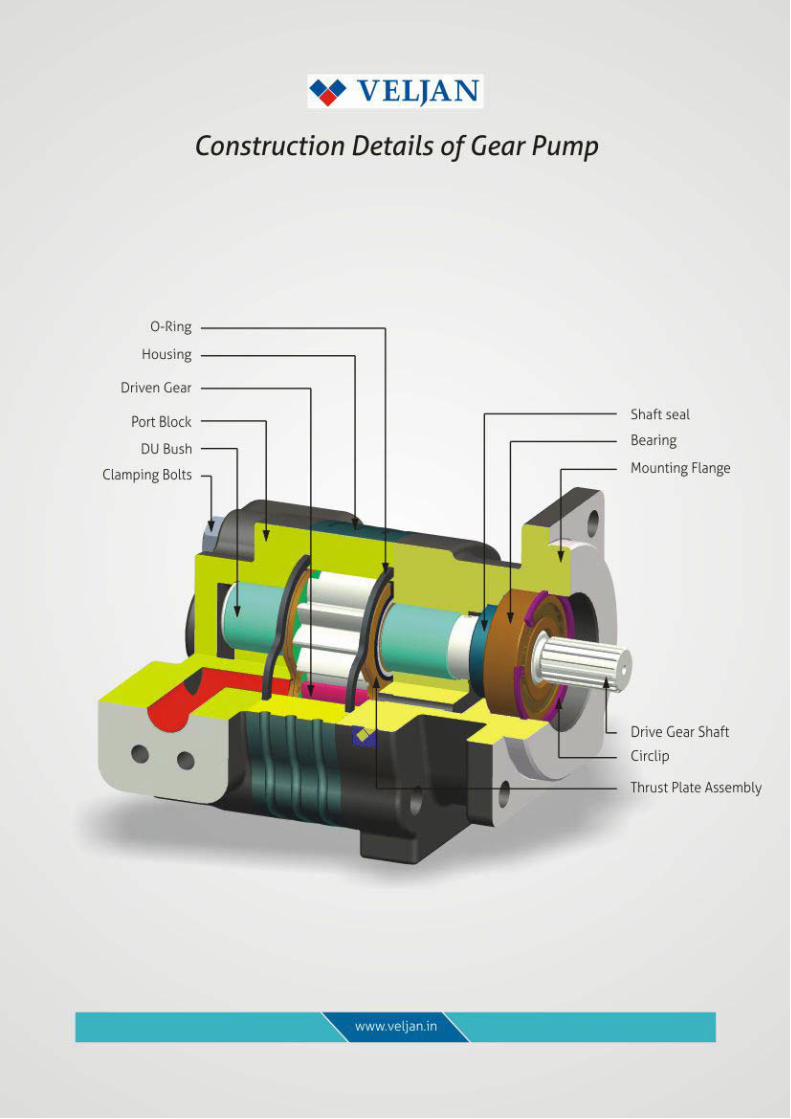
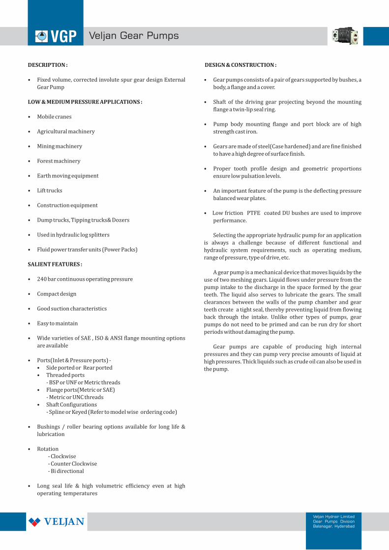
DESCRIPTION : DESIGN & CONSTRUCTION :
• Fixed volume, corrected involute spur gear design External • Gear pumps consists of a pair of gears supported by bushes, a
Gear Pump body, a flange and a cover.
LOW & MEDIUM PRESSURE APPLICATIONS : • Shaft of the driving gear projecting beyond the mounting
flange a twin-lip seal ring.• Mobile cranes
• Pump body mounting flange and port block are of high • Agricultural machinery strength cast iron.
• Mining machinery • Gears are made of steel(Case hardened) and are fine finished
to have a high degree of surface finish. • Forest machinery
• Proper tooth profile design and geometric proportions • Earth moving equipment ensure low pulsation levels.
• Lift trucks • An important feature of the pump is the deflecting pressure
balanced wear plates.• Construction equipment
• Low friction PTFE coated DU bushes are used to improve • Dump trucks, Tipping trucks& Dozers performance.
• Used in hydraulic log splitters Selecting the appropriate hydraulic pump for an application
is always a challenge because of different functional and • Fluid power transfer units (Power Packs) hydraulic system requirements, such as operating medium,
range of pressure, type of drive, etc. SALIENT FEATURES :
A gear pump is a mechanical device that moves liquids by the • 240 bar continuous operating pressure use of two meshing gears. Liquid flows under pressure from the
pump intake to the discharge in the space formed by the gear • Compact design teeth. The liquid also serves to lubricate the gears. The small
clearances between the walls of the pump chamber and gear • Good suction characteristics teeth create a tight seal, thereby preventing liquid from flowing
back through the intake. Unlike other types of pumps, gear • Easy to maintain pumps do not need to be primed and can be run dry for short
periods without damaging the pump.• Wide varieties of SAE , ISO & ANSI flange mounting options
are available Gear pumps are capable of producing high internal
pressures and they can pump very precise amounts of liquid at • Ports(Inlet & Pressure ports) - high pressures. Thick liquids such as crude oil can also be used in
• Side ported or Rear ported the pump.• Threaded ports
- BSP or UNF or Metric threads
• Flange ports(Metric or SAE)
- Metric or UNC threads
• Shaft Configurations
- Spline or Keyed (Refer to model wise ordering code)
• Bushings / roller bearing options available for long life &
lubrication
• Rotation
- Clockwise
- Counter Clockwise
- Bi directional
• Long seal life & high volumetric efficiency even at high
operating temperatures
Veljan Gear Pumps
Veljan Hydrair LimitedGear Pumps DivisionBalanagar, Hyderabad
Veljan Gear Pumps
Veljan Hydrair LimitedGear Pumps DivisionBalanagar, Hyderabad
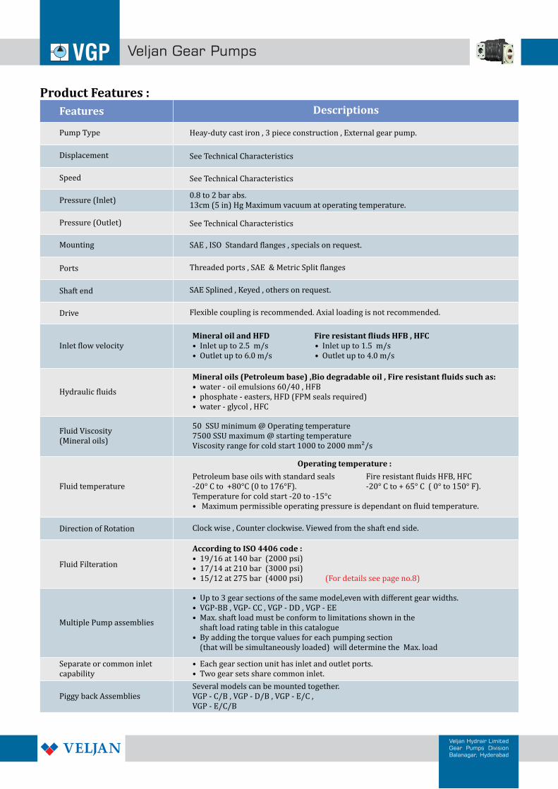
Product Features :
DescriptionsFeatures
Pump Type
Displacement
Speed
Pressure (Inlet)
Pressure (Outlet)
Mounting
Ports
Shaft end
Drive
Inlet flow velocity
Hydraulic fluids
Fluid Viscosity(Mineral oils)
Fluid temperature
Direction of Rotation
Fluid Filteration
Multiple Pump assemblies
Separate or common inletcapability
Piggy back Assemblies
Heay-duty cast iron , 3 piece construction , External gear pump.
See Technical Characteristics
See Technical Characteristics
0.8 to 2 bar abs.13cm (5 in) Hg Maximum vacuum at operating temperature.
See Technical Characteristics
SAE , ISO Standard flanges , specials on request.
Threaded ports , SAE & Metric Split flanges
SAE Splined , Keyed , others on request.
Flexible coupling is recommended. Axial loading is not recommended.
Mineral oil and HFD • Inlet up to 2.5 m/s • Outlet up to 6.0 m/s • Outlet up to 4.0 m/s
Fire resistant fliuds HFB , HFC• Inlet up to 1.5 m/s
Mineral oils (Petroleum base) ,Bio degradable oil , Fire resistant fluids such as:water - oil emulsions 60/40 , HFB
• phosphate - easters, HFD (FPM seals required)• water - glycol , HFC
•
50 SSU minimum @ Operating temperature7500 SSU maximum @ starting temperatureViscosity range for cold start 1000 to 2000 mm²/s
Several models can be mounted together.VGP - C/B , VGP - D/B , VGP - E/C ,VGP - E/C/B
• • Two gear sets share common inlet.
Each gear section unit has inlet and outlet ports.
According to ISO 4406 code :19/16 at 140 bar (2000 psi)
• 17/14 at 210 bar (3000 psi)• 15/12 at 275 bar (4000 psi)
•
(For details see page no.8)
Clock wise , Counter clockwise. Viewed from the shaft end side.
Petroleum base oils with standard seals-20° C to +80°C (0 to 176°F).Temperature for cold start -20 to -15°c• Maximum permissible operating pressure is dependant on fluid temperature.
Fire resistant fluids HFB, HFC-20° C to + 65° C ( 0° to 150° F).
Operating temperature :
• Up to 3 gear sections of the same model,even with different gear widths.• VGP-BB , VGP- CC , VGP - DD , VGP - EE• Max. shaft load must be conform to limitations shown in the shaft load rating table in this catalogue• By adding the torque values for each pumping section (that will be simultaneously loaded) will determine the Max. load
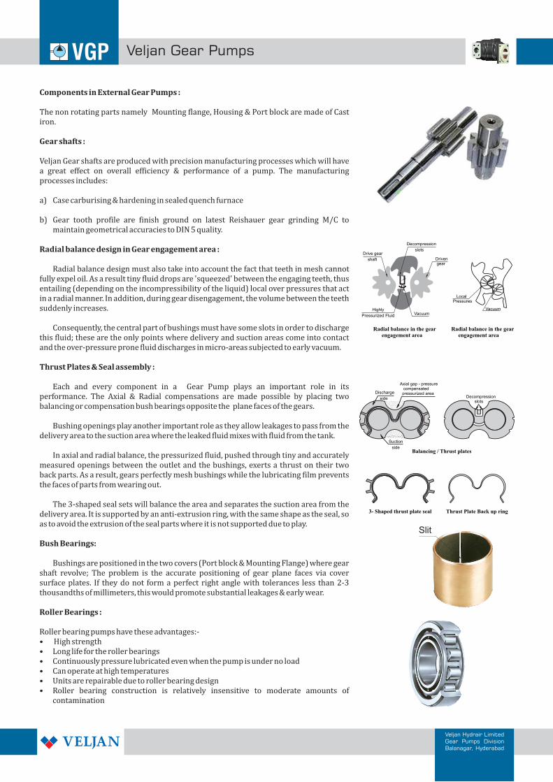
Components in External Gear Pumps :
The non rotating parts namely Mounting flange, Housing & Port block are made of Cast iron.
Gear shafts :
Veljan Gear shafts are produced with precision manufacturing processes which will have a great effect on overall efficiency & performance of a pump. The manufacturing processes includes:
a) Case carburising & hardening in sealed quench furnace
b) Gear tooth profile are finish ground on latest Reishauer gear grinding M/C to maintain geometrical accuracies to DIN 5 quality.
Radial balance design in Gear engagement area :
Radial balance design must also take into account the fact that teeth in mesh cannot fully expel oil. As a result tiny fluid drops are 'squeezed' between the engaging teeth, thus entailing (depending on the incompressibility of the liquid) local over pressures that act in a radial manner. In addition, during gear disengagement, the volume between the teeth suddenly increases.
Consequently, the central part of bushings must have some slots in order to discharge this fluid; these are the only points where delivery and suction areas come into contact and the over-pressure prone fluid discharges in micro-areas subjected to early vacuum.
Thrust Plates & Seal assembly :
Each and every component in a Gear Pump plays an important role in its performance. The Axial & Radial compensations are made possible by placing two balancing or compensation bush bearings opposite the plane faces of the gears.
Bushing openings play another important role as they allow leakages to pass from the delivery area to the suction area where the leaked fluid mixes with fluid from the tank.
In axial and radial balance, the pressurized fluid, pushed through tiny and accurately measured openings between the outlet and the bushings, exerts a thrust on their two back parts. As a result, gears perfectly mesh bushings while the lubricating film prevents the faces of parts from wearing out.
The 3-shaped seal sets will balance the area and separates the suction area from the delivery area. It is supported by an anti-extrusion ring, with the same shape as the seal, so as to avoid the extrusion of the seal parts where it is not supported due to play.
Bush Bearings:
Bushings are positioned in the two covers (Port block & Mounting Flange) where gear shaft revolve; The problem is the accurate positioning of gear plane faces via cover surface plates. If they do not form a perfect right angle with tolerances less than 2-3 thousandths of millimeters, this would promote substantial leakages & early wear.
Roller Bearings :
Roller bearing pumps have these advantages:-• High strength • Long life for the roller bearings• Continuously pressure lubricated even when the pump is under no load• Can operate at high temperatures• Units are repairable due to roller bearing design• Roller bearing construction is relatively insensitive to moderate amounts of
contamination
Radial balance in the gear engagement area
Radial balance in the gear engagement area
Decompression
slots
Highly
Pressurized Fluid Vacuum
Drive gear
shaft Driven gear
Vacuum
Local Pressures
Decompression slots
Balancing / Thrust plates
Discharge
side
Axial gap - pressure compensated pressurized area
Suction
side
3- Shaped thrust plate seal Thrust Plate Back up ring
Slit
Veljan Gear Pumps
Veljan Hydrair LimitedGear Pumps DivisionBalanagar, Hyderabad
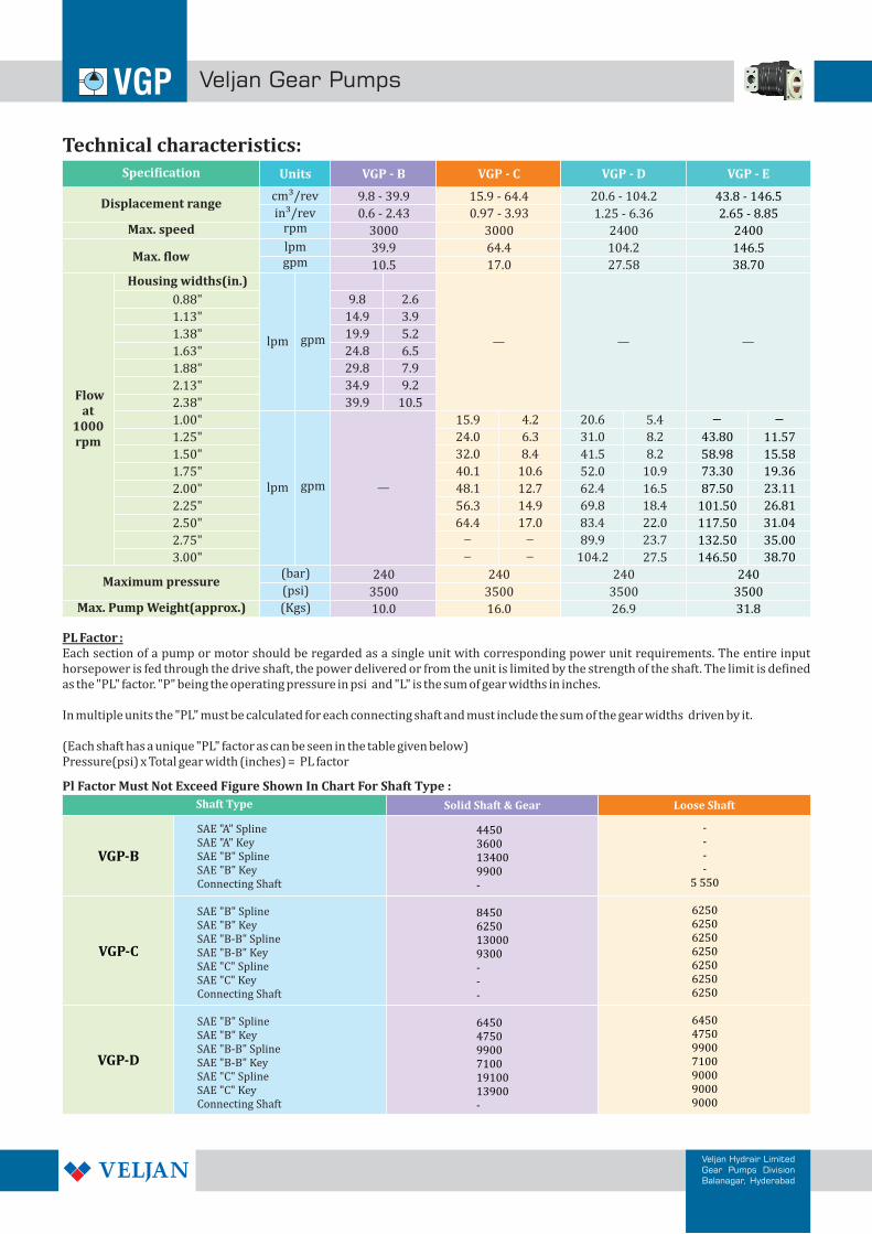
Technical characteristics:
Veljan Gear Pumps
Veljan Hydrair LimitedGear Pumps DivisionBalanagar, Hyderabad
PL Factor :Each section of a pump or motor should be regarded as a single unit with corresponding power unit requirements. The entire input horsepower is fed through the drive shaft, the power delivered or from the unit is limited by the strength of the shaft. The limit is defined as the "PL" factor. "P" being the operating pressure in psi and "L" is the sum of gear widths in inches.
In multiple units the "PL" must be calculated for each connecting shaft and must include the sum of the gear widths driven by it.
(Each shaft has a unique "PL" factor as can be seen in the table given below)Pressure(psi) x Total gear width (inches) = PL factor
VGP - B VGP - C VGP - D
9.8
14.9
19.9
24.8
29.8
34.9
39.9
2.6
3.9
5.2
6.5
7.9
9.2
10.5
15.9
24.0
32.0
40.1
48.1
56.3
64.4
4.2
6.3
8.4
10.6
12.7
14.9
17.0
20.6
31.0
41.5
52.0
62.4
69.8
83.4
89.9
104.2
5.4
8.2
8.2
10.9
16.5
18.4
22.0
23.7
27.5
240 240 240
3500 3500 3500
Specification
Displacement range
Max. speed
Max. flow
Flowat
1000rpm
Housing widths(in.)
0.88"
1.13"
1.38"
1.63"
1.88"
2.13"
2.38"
1.00"
1.25"
1.50"
1.75"
2.00"
2.25"
2.50"
2.75"
3.00"
Maximum pressure
Max. Pump Weight(approx.)
Units
cm³/rev
in³/revrpm
lpmgpm
lpm gpm
lpm gpm
(bar)
(psi)
(Kgs) 10.0 16.0 26.9
9.8 - 39.9
0.6 - 2.43
15.9 - 64.4
0.97 - 3.93
20.6 - 104.2
1.25 - 6.36
3000 3000 2400
39.9
10.5
64.4
17.0
104.2
27.58
VGP - E
43.8 - 146.5
2.65 - 8.85
2400
146.5
38.70
87.50
101.50
117.50
132.50
146.50
23.11
26.81
31.04
35.00
38.70
73.30 19.36
240
3500
31.8
58.98 15.58
43.80 11.57
Shaft Type Solid Shaft & Gear Loose Shaft
VGP-B
44503600134009900-
84506250130009300---
64504750990071001910013900-
----
5 550
6250625062506250625062506250
6450475099007100900090009000
VGP-C
VGP-D
Pl Factor Must Not Exceed Figure Shown In Chart For Shaft Type :
SAE "A" SplineSAE "A" KeySAE "B" SplineSAE "B" KeyConnecting Shaft
SAE "B" SplineSAE "B" KeySAE "B-B" SplineSAE "B-B" KeySAE "C" SplineSAE "C" KeyConnecting Shaft
SAE "B" SplineSAE "B" KeySAE "B-B" SplineSAE "B-B" KeySAE "C" SplineSAE "C" KeyConnecting Shaft
Application Guide Lines
Veljan Gear Pumps
Veljan Hydrair LimitedGear Pumps DivisionBalanagar, Hyderabad
Inlet Conditions:Recommended below should be followed at inlet condition of the pump:
• Never run pumps without oil - Particular care should be taken to open any shut-off valves.
• Use large diameter pipes and fittings and avoid sharp bends, elbows and long length lines.
• Pumps must be mounted below the lowest level of fluid tank as much as possible.
• Ensure that inlet lines are airtight.
• Be carefully in case there is high speed and/or high viscosity fluids are used in system.
• Fluid inlet velocity should not exceed 2.5m/sec (8.0 ft/sec ) calculated by:
V = (21.22*Q)/D² 3/sec where V= 0.0408Q/D² ft/sec where V = velocity (m/sec) V = velocity (ft/sec)Q = Flow range (l/min) Q = flow rate (US gal/min)D Bore diameter (mm) D = bore diameter (inches)
Cavitation:Hydraulic oil used in the modern hydraulic systems contains approximately 10% dissolved air by volume and this air implodes at certain pressure creating air pockets that can damage on metal surfaces. The main reasons are especially leakages in the suction port, unsuitable pipe sizes, elbow fittings and sudden changes in flow line.
Operating Temperature:Operating temperatures are the function of fluid visosities, fluid type, and the pump. For cold starts, the pumps should be operated at low speed and pressure until fluid warms up to an acceptable viscosity.• For NBR seals between 0°C and +80°C continuously and between -20°C and +100°C intermittent.• For VITON seals between 0°C and +100°C continuously and between -20°C and +120°C intermittent.
Inlet pressureUnder standard working conditions, intake pipe pressure is lower than the atmospheric pressure.The operating inlet pressure should range between 0.7 and 3 bars (absolute).
Hydraulic fluids:We recommend you to use only mineral oil-based hydraulic fluids having good anti-wear, anti-foaming (rapid de-aeration), antioxidant, anti-corrosion and lubricating properties. The fluids comply with the DIN/ISO or SAE standards Recommended viscosity range is 20/120(cSt) and permitted up to 700(cSt). If Hydraulic oil changes according to that the seals has to be changed.
For Mineral oil (Acc. ISO/ DIN) - NBR/FPM at temp.( -15 to + 83°C ) Fluid composition:- - HFB - NBR at temp.( +2 to + 65°C ) HFB - Water - in - oil emulsion 40/60- HFC - NBR at temp.( -15 to + 65°C ) HFC - Water - glycol 40/60- HFD - FPM at temp.( -10 to + 80°C ) HFD - Phosphate ester
Shaft alignment :
Splined :1. The permissible maximum misalignment is 0.06 mm (0.002 in) TIR for foot mounted pump and 0.03 mm (0.001 in) in case of flange
mounted pump. The angular misalignment between the shaft splines and the coupling internal splines should be less than +/- 0.002 mm per mm diameter of the pump shaft.
Keyed :1. These are supplied with matching Keys and in case replacement becomes necessary, use only high strength heat treated steel keys with
hardness of 27-34 Rc. The key corners must be chamfered properly so that it locates snugly in the keyway.
Veljan Gear Pumps
Veljan Hydrair LimitedGear Pumps DivisionBalanagar, Hyderabad
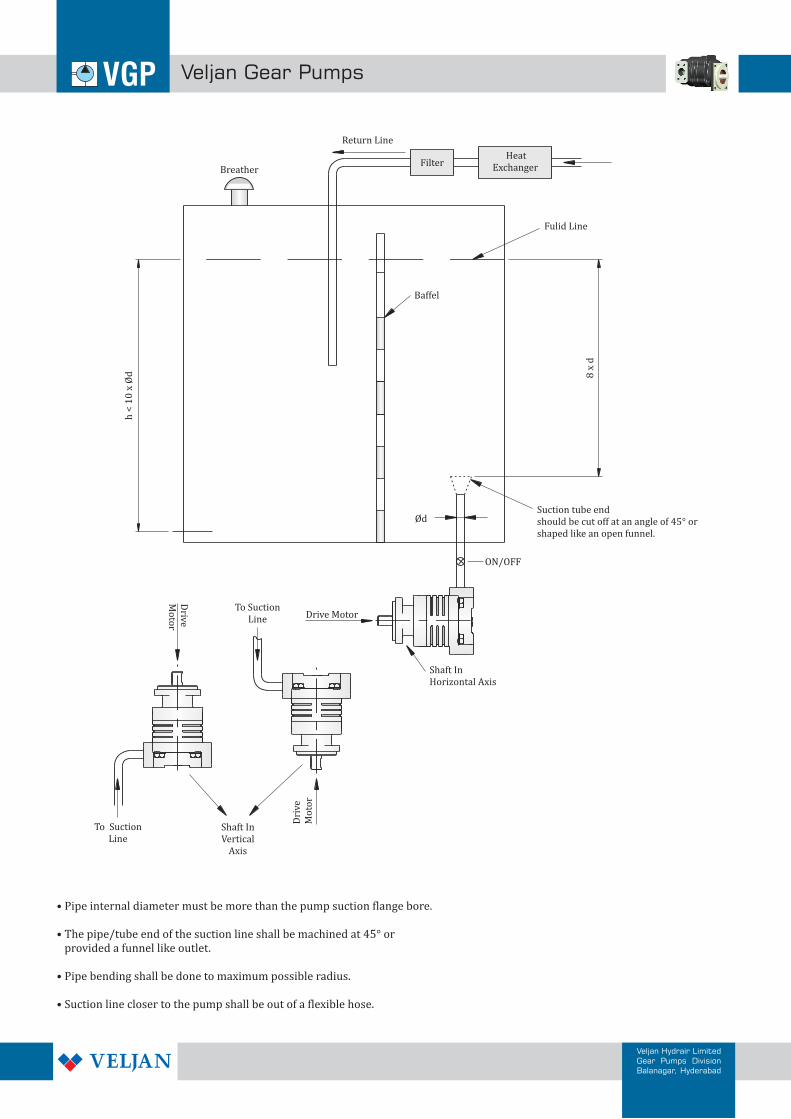
Filter Heat Exchanger
Return Line
Drive MotorTo Suction
Line
Dri
ve
Mo
tor
To SuctionLine
Drive
Mo
tor
Shaft In Vertical
Axis
Shaft In Horizontal Axis
Suction tube endshould be cut off at an angle of 45° or shaped like an open funnel.
ON/OFF
Ød
h <
10
x Ø
d 8 x
d
Baffel
Fulid Line
Breather
• Pipe internal diameter must be more than the pump suction flange bore.
• The pipe/tube end of the suction line shall be machined at 45° or provided a funnel like outlet.
• Pipe bending shall be done to maximum possible radius.
• Suction line closer to the pump shall be out of a flexible hose.
ParticlesSizeRange
MaximumParticles
5-15µm
15-25µm
25-50µm
50-100µm
>5µm
>15µm
>100µm
7
32,000
5,700
180
32
1,012
38,924
6,924
6
16,000
2,850
90
16
506
19,462
3,462
5
8,000
1,425
45
8
253
9,731
1,731
4
4,000
712
22
4
126
4,864
864
3
2,000
356
11
2
63
2,432
432
2
1,000
178
6
1
32
1,217
217
1
500
89
3
1
16
609
109
00
125
22
1
0
4
152
27
0
250
44
2
0
3
304
54
CLASS
8 9 10 11 12
64,000
11,400
360
64
2,025
128,000
22,800
720
128
4,050
256,000
45,600
1,440
256
8,100
512,000
91,200
2,880
512
16,200
1,024,000
182,400
5,760
1,024
32,400
77,849 155,698 311,396 622,792 1,245,584
13,849 27,698 55,396 110,792 221,584
>5µm
>15µm
ISO solid contamination code
8/5 9/6 10/7 11/8 12/9 13/10 14/11 15/12 16/13 17/14 18/15 19/16 20/17 21/18
250
32
500
64
1000
130 250 500 1000 2000 4000 8000 16,000 32,000 64,000 130,000
22/19
2000 4000 8000 16000 32000 64000 130,000 250,000 500,000 1,000,000 2,000,000 4,000,000
250,000 500,000MaximumParticles
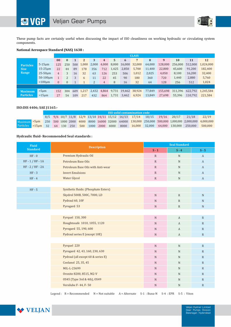
ISO:DIS 4406; SAE J1165:-
These pump facts are certainly useful when discussing the impact of ISO cleanliness on working hydraulic or circulating system components.
National Aerospace Standard (NAS) 1638 :
Hydraulic fluid- Recommended Seal standards :
Fluid Standard
DescriptionSeal Standard
S - 1 S - 4 S - 5
HF - 0 R N A
R
R
R
N A
N A
N A
HF - 1 / HF - 1A
HF - 2 / HF - 2A
HF - 3
HF - 4 R N A
HF - 5
N
N
N
R
R
R
N
N
N
N
N
N
N
A
A
A
A
R
R
R
R
N
N
N
N
R
R
R
R
N
N
N
N
Premium Hydraulic Oil
Petroleum Base Oils
Petroleum Base Oils with Anti-wear
Invert Emulsions
Water Glycol
Synthetic fluids: (Phosphate Esters)
Skydrol 500B, 500C, 7000, LD
Pydraul 60, 10F
Pyrogard 53
Fyrquel 150, 300
Houghtosafe 1010, 1055, 1120
Pyrogard 55, 190, 600
Pydraul series E (except 10E)
Fyrquel 220
Coolanol 25, 35, 45
Pyrogard 42, 43, 160, 230, 630
Pydraul (all except 60 & series E)
MIL-L-23699
Oronite 8200, 8515, M2-V
OS45 (Type 3rd & 4th), OS49
Versilube F- 44, F- 50
N
N
N
N
R
R
R
R
N
N
N
N
Legend : R = Recommended N = Not suitable A = Alternate S-1 : Buna-N S-4 : EPR S-5 : Viton
Veljan Gear Pumps
Veljan Hydrair LimitedGear Pumps DivisionBalanagar, Hyderabad
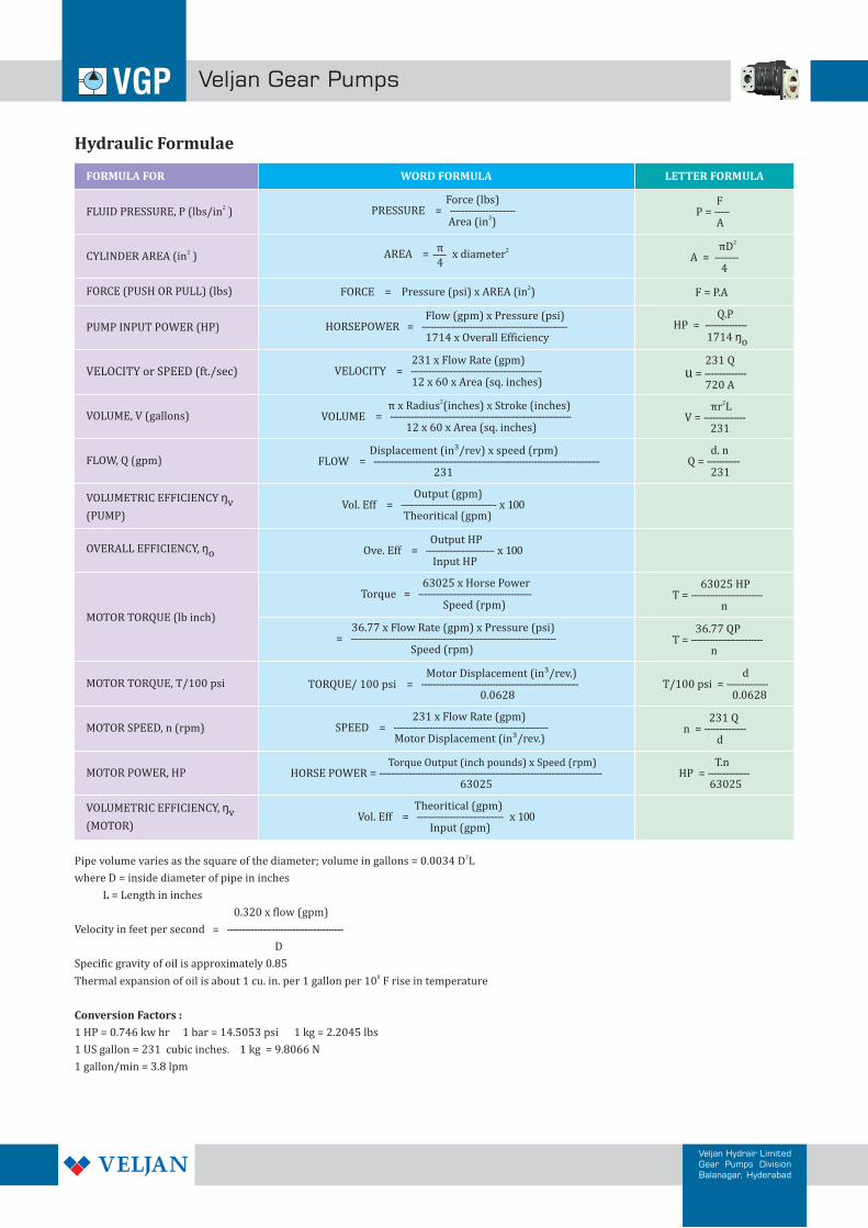
Hydraulic Formulae
WORD FORMULA LETTER FORMULAFORMULA FOR
2FLUID PRESSURE, P (lbs/in )
2CYLINDER AREA (in )
FORCE (PUSH OR PULL) (lbs)
VOLUME, V (gallons)
FLOW, Q (gpm)
VOLUMETRIC EFFICIENCY
(PUMP)
ŋv
OVERALL EFFICIENCY, ŋo
2AREA x diameter = π
4
2FORCE = Pressure (psi) x AREA (in )
231 x Flow Rate (gpm)VELOCITY = -------------------------------------------- 12 x 60 x Area (sq. inches)
Force (lbs)PRESSURE = ----------------------
2 Area (in )
2 π x Radius (inches) x Stroke (inches)VOLUME = ------------------------------------------------------------- 12 x 60 x Area (sq. inches)
Displacement (in³/rev) x speed (rpm)FLOW = ---------------------------------------------------------------------------- 231
Output (gpm)Vol. Eff = -------------------------------- x 100 Theoritical (gpm)
Output HPOve. Eff = ----------------------- x 100 Input HP
FP = ----- A
2 πDA = -------- 4
F = P.A
Q.PHP = -------------- 1714 ŋo
231 Q = --------------
720 Au
2 πr LV = -------------- 231
d. nQ = ----------- 231
MOTOR TORQUE (lb inch)
MOTOR TORQUE, T/100 psi
MOTOR SPEED, n (rpm)
MOTOR POWER, HP
VOLUMETRIC EFFICIENCY,
(MOTOR)
ŋv
63025 x Horse PowerTorque = -------------------------------------- Speed (rpm)
36.77 x Flow Rate (gpm) x Pressure (psi)= --------------------------------------------------------------------- Speed (rpm)
Motor Displacement (in³/rev.)TORQUE/ 100 psi = ----------------------------------------------------- 0.0628
231 x Flow Rate (gpm)SPEED = ---------------------------------------------------- Motor Displacement (in³/rev.)
Torque Output (inch pounds) x Speed (rpm)HORSE POWER = --------------------------------------------------------------------------- 63025
Theoritical (gpm)Vol. Eff = ----------------------------- x 100 Input (gpm)
63025 HPT = ------------------------ n
36.77 QPT = ------------------------ n
dT/100 psi = -------------- 0.0628
231 Qn = -------------- d
T.nHP = -------------- 63025
2Pipe volume varies as the square of the diameter; volume in gallons = 0.0034 D L
where D = inside diameter of pipe in inches
L = Length in inches
0.320 x flow (gpm)
Velocity in feet per second = ---------------------------------------
D
Specific gravity of oil is approximately 0.850Thermal expansion of oil is about 1 cu. in. per 1 gallon per 10 F rise in temperature
Conversion Factors :
1 HP = 0.746 kw hr 1 bar = 14.5053 psi 1 kg = 2.2045 lbs
1 US gallon = 231 cubic inches. 1 kg = 9.8066 N
1 gallon/min = 3.8 lpm
VELOCITY or SPEED (ft./sec)
Flow (gpm) x Pressure (psi)HORSEPOWER = ------------------------------------------------- 1714 x Overall Efficiency
PUMP INPUT POWER (HP)
Veljan Gear Pumps
Veljan Hydrair LimitedGear Pumps DivisionBalanagar, Hyderabad
Veljan Gear Pumps
Veljan Hydrair LimitedGear Pumps DivisionBalanagar, Hyderabad
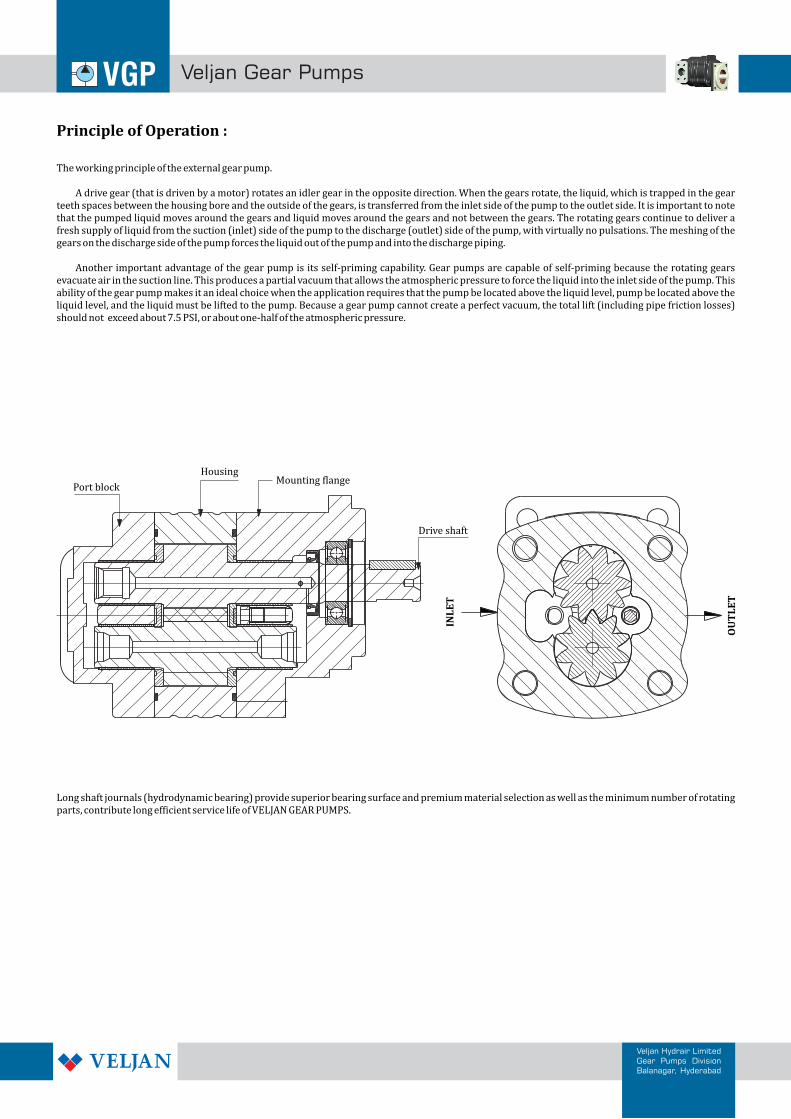
Principle of Operation :
The working principle of the external gear pump.
A drive gear (that is driven by a motor) rotates an idler gear in the opposite direction. When the gears rotate, the liquid, which is trapped in the gear teeth spaces between the housing bore and the outside of the gears, is transferred from the inlet side of the pump to the outlet side. It is important to note that the pumped liquid moves around the gears and liquid moves around the gears and not between the gears. The rotating gears continue to deliver a fresh supply of liquid from the suction (inlet) side of the pump to the discharge (outlet) side of the pump, with virtually no pulsations. The meshing of the gears on the discharge side of the pump forces the liquid out of the pump and into the discharge piping.
Another important advantage of the gear pump is its self-priming capability. Gear pumps are capable of self-priming because the rotating gears evacuate air in the suction line. This produces a partial vacuum that allows the atmospheric pressure to force the liquid into the inlet side of the pump. This ability of the gear pump makes it an ideal choice when the application requires that the pump be located above the liquid level, pump be located above the liquid level, and the liquid must be lifted to the pump. Because a gear pump cannot create a perfect vacuum, the total lift (including pipe friction losses) should not exceed about 7.5 PSI, or about one-half of the atmospheric pressure.
Long shaft journals (hydrodynamic bearing) provide superior bearing surface and premium material selection as well as the minimum number of rotating parts, contribute long efficient service life of VELJAN GEAR PUMPS.
INL
ET
OU
TL
ET
Mounting flangeHousing
Drive shaft
Port block
3
12 14 15
13
5 6
4 6 5 5 1011
10
10 11 106 5 4 3
2
20 3
19 18 17
1
9
3 4 5 6 8
7
2
Veljan Gear Pumps
Veljan Hydrair LimitedGear Pumps DivisionBalanagar, Hyderabad
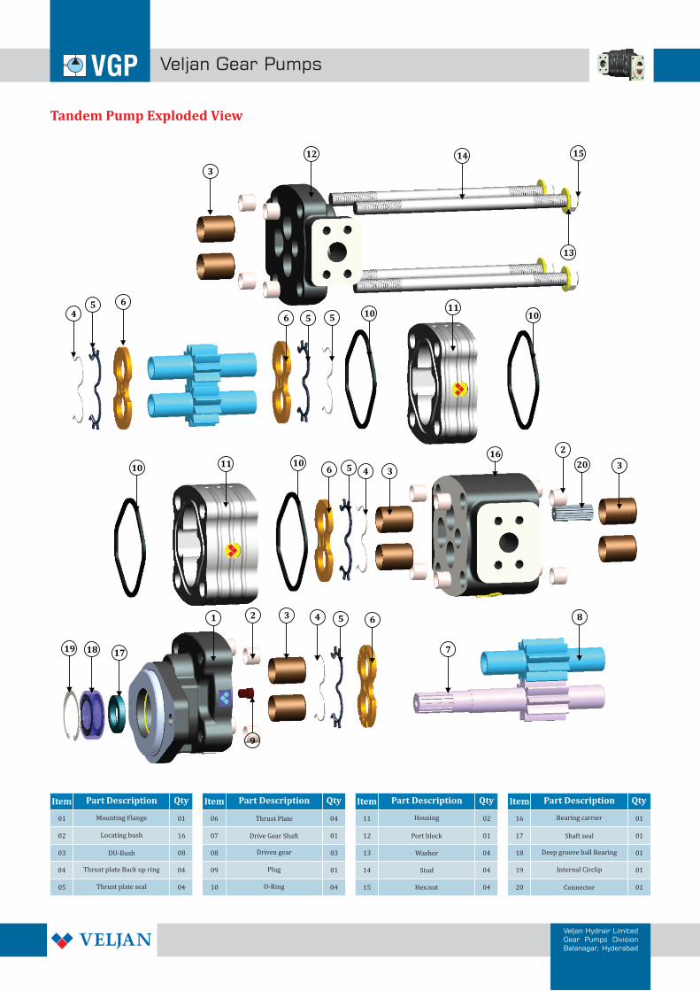
Tandem Pump Exploded View
Item ItemItemItemPart Description Part DescriptionPart DescriptionPart DescriptionQty QtyQtyQty
01
02
03
04
05 Thrust plate seal
Thrust plate Back up ring
DU-Bush
Locating bush
Mounting Flange 01
16
08
04
04
06
07
08
09
10
Driven gear
04
01
03
01
04
11
12
13
14
15
Housing
Port block
Washer
Stud
Hex.nut
02
01
04
04
04
16
17
18
19
20
Bearing carrier
Shaft seal
Deep groove ball Bearing
Internal Circlip
Connector
01
01
01
01
01
16
Thrust Plate
Drive Gear Shaft
Plug
O-Ring
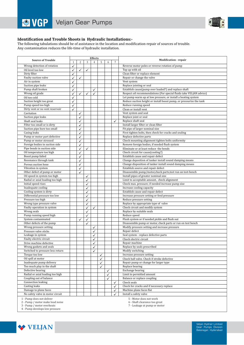
Identification and Trouble Shoots in Hydraulic Installations:-The following tabulations should be of assistance in the location and modification-repair of sources of trouble.Any contamination reduces the life-time of hydraulic installation.
1 - Pump does not deliver2 - Pump / motor make loud noise3 - Pump / motor overheats4 - Pump develops low pressure
5 - Motor does not work6 - Shaft clearance too great7 - Leakage at pump or motor
Source of TroubleEffects
Modification - repair1 2 3 4 5 6 7
Veljan Gear Pumps
Veljan Hydrair LimitedGear Pumps DivisionBalanagar, Hyderabad
Wrong detection of rotation
Oil level too low
Dirty filter
Faulty suction valve
Air in system
Suction pipe leaks
Pump shaft broken
Wrong oil grade
Oil too cold
Suction height too great
Pump speed too high
Dirty vent or no vent reservoir
Cavitation
Suction pipe leaks
Shaft seal leaks
Filter too small or is dirty
Suction pipe bore too small
Casing leaks
Pump or motor part defective
Pump or motor stressed
Foreign bodies in suction side
Pipe bends in suction side
Oil temperature too high
Boost pump failed
Resonance through tank
Porous suction hose
Vibration in system
Other defect of pump or motor
Oil speed in system too high
Radial or axial loading too high
Initial speed rises
Inadequate cooling
Cooling system is dirty
Differential pressure too low
Pressure too high
Wrong type pressure valve
Faulty operation in system
Wrong seals
Pump running speed high
System contaminated
Other defects of the pump
Wrong pressure setting
Pressure valve sticks
Leakage in system
Faulty electric circuit
Drive machine defective
Wrong gaskets and seals
Switched to pressure less return
Torque too low
Oil spill at motor
Inadequate pump delivery
Too much play in the shaft
Defective bearing
Radial or axial loading too high
Coupling out of balance
Connection leaking
Casting leaks
Damage to plane faces
No safety valve in motor circuit
Reverse motor poles or reverse rotation of pump
Top up with oil
Clean filter or replace element
Repair or change the valve
Vent system
Replace jointing or seal
Establish cause(pump over loaded?) and replace shaft
Respect oil recommendations (For special fluids take VELJAN advice)
Let pump warm up at low pressure, or install a heating system
Reduce suction height or install boost pump, or pressurize the tank
Reduce running speed
Clean or install vent
Vent system and seal
Replace joint or seal
Replace shaft seal
Install larger filter or clean filter
Fit pipe of larger nominal size
First tighten bolts, then check for cracks and sealing
Replace defective parts
Check mounting alignment tighten bolts uniformity
Remove foreign bodies, if needed flush system
Eliminate or at least reduce the bends
Check circuit for cause(cooling?)
Establish cause and repair defect
Change deposition of tanker install sound damping means
Change disposition of tanker install sound damping means
Establish source and repair defect
Disassemble pump/motor,check parts,test run on test-bench
Install pipes of greater nominal size
Limit to acceptable amount, check alignment
Check max. pressure; if needed increase pump size
Increase cooling capacity
Establish cause and repair defect
Increase pressure setting or feed pressure
Reduce pressure setting
Replace by appropriate type of valve
Check circuit and modify system
Replace by suitable seals
Reduce speed
Flush system or if needed pickle and flush out
Disassemble pump or motor, check parts or run on test bench
Modify pressure setting and increase pressure
Repair defect
Seal system - replace defective parts
Check electric circuit
Repair machine
Replace by seals prescribed
Modify switching
Increase pressure setting
Check ball valve. Check if stroke defective
Repair pump or change for larger type
Replace bearing
Exchange bearing
Limit to permitted amount
Balance or replace coupling
Check seals
Check for cracks and if necessary replace
Machine plane faces flat
Install a safety valve
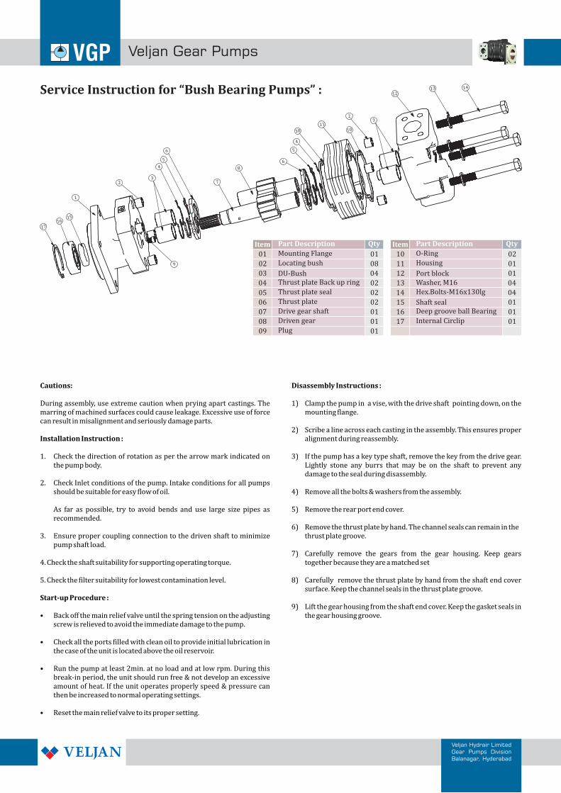
Service Instruction for “Bush Bearing Pumps” :
1
23
4
5
6
7
8
6
5
4
10
11
9
2
10
3
1213 14
15 16
17
Item Qty
01 01
02 01
03 01
04
01
05
01
06 02
07
02
08
02
09
10
08 11
01
12
01
13
14
01
15
04
16
04
17
04
Part Description
Mounting Flange
Drive gear shaft
Driven gear
Thrust plate
Thrust plate seal
Thrust plate Back up ring
Locating bush
Plug
DU-Bush
02
01
Item
Housing
Port block
Shaft seal
Internal Circlip
Washer, M16 Hex.Bolts-M16x130lg
O-Ring
Deep groove ball Bearing
Part Description Qty
Veljan Gear Pumps
Veljan Hydrair LimitedGear Pumps DivisionBalanagar, Hyderabad
Cautions: Disassembly Instructions :
During assembly, use extreme caution when prying apart castings. The 1) Clamp the pump in a vise, with the drive shaft pointing down, on the marring of machined surfaces could cause leakage. Excessive use of force mounting flange.can result in misalignment and seriously damage parts.
2) Scribe a line across each casting in the assembly. This ensures proper Installation Instruction : alignment during reassembly.
1. Check the direction of rotation as per the arrow mark indicated on 3) If the pump has a key type shaft, remove the key from the drive gear. the pump body. Lightly stone any burrs that may be on the shaft to prevent any
damage to the seal during disassembly.2. Check Inlet conditions of the pump. Intake conditions for all pumps
should be suitable for easy flow of oil. 4) Remove all the bolts & washers from the assembly.
As far as possible, try to avoid bends and use large size pipes as 5) Remove the rear port end cover.recommended.
6) Remove the thrust plate by hand. The channel seals can remain in the3. Ensure proper coupling connection to the driven shaft to minimize thrust plate groove.
pump shaft load.7) Carefully remove the gears from the gear housing. Keep gears
4. Check the shaft suitability for supporting operating torque. together because they are a matched set
5. Check the filter suitability for lowest contamination level. 8) Carefully remove the thrust plate by hand from the shaft end cover surface. Keep the channel seals in the thrust plate groove.
Start-up Procedure :9) Lift the gear housing from the shaft end cover. Keep the gasket seals in
• Back off the main relief valve until the spring tension on the adjusting the gear housing groove.screw is relieved to avoid the immediate damage to the pump.
• Check all the ports filled with clean oil to provide initial lubrication in the case of the unit is located above the oil reservoir.
• Run the pump at least 2min. at no load and at low rpm. During this break-in period, the unit should run free & not develop an excessive amount of heat. If the unit operates properly speed & pressure can then be increased to normal operating settings.
• Reset the main relief valve to its proper setting.
Veljan Gear Pumps
Veljan Hydrair LimitedGear Pumps DivisionBalanagar, Hyderabad
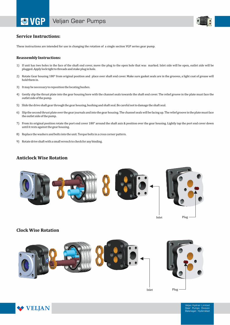
Service Instructions:
Anticlock Wise Rotation
These instructions are intended for use in changing the rotation of a single section VGP series gear pump.
Reassembly Instructions:
1) If unit has two holes in the face of the shaft end cover, move the plug to the open hole that was marked. Inlet side will be open, outlet side will be plugged. Apply lock tight to threads and stake plug in hole.
2) Rotate Gear housing 180° from original position and place over shaft end cover. Make sure gasket seals are in the grooves, a light coat of grease will hold them in.
3) It may be necessary to reposition the locating bushes.
4) Gently slip the thrust plate into the gear housing bore with the channel seals towards the shaft end cover. The relief groove in the plate must face the outlet side of the pump.
5) Slide the drive shaft gear through the gear housing, bushing and shaft seal. Be careful not to damage the shaft seal.
6) Slip the second thrust plate over the gear journals and into the gear housing. The channel seals will be facing up. The relief groove in the plate must face the outlet side of the pump.
7) From its original position rotate the port end cover 180° around the shaft axis & position over the gear housing. Lightly tap the port end cover down until it rests against the gear housing.
8) Replace the washers and bolts into the unit. Torque bolts in a cross corner pattern.
9) Rotate drive shaft with a small wrench to check for any binding.
PlugInlet
Clock Wise Rotation
PlugInlet

Veljan Gear Pumps
Veljan Hydrair LimitedGear Pumps DivisionBalanagar, Hyderabad
Service Instructions:
Seal replacement Instructions
Important: Note the shape and orientation of all seals before and during removal.
The first requirement for good maintenance of hydraulic Pump or equipment is cleanliness. extreme cleanliness is most important in hydraulic system.
MAKE SURE THE MAINTENANCE OF YOUR HYDRAULIC EQUIPMENT IN A CLEAN AREA
Shaft seal:
1) If shaft end cover has circlip (or) smalley ring and outboard bearing, carefully remove. Insert small diameter punch from inside cover into shaft seal opening. Gently tap to drive out the lip seal.
2) Apply a light coat of non-hardening gasket sealant in the outer edge of the replacement seal. Press the seal flush with the seal recess in the shaft end cover.
Gear Housing Gasket Seals:
1) Carefully remove seals in groove.
2) Insert new seals in grooves. Apply a light coat of grease to seals to hold it in place during reassembly of pump.
Thrust plate Seals:
1) Remove the back-up seal and channel seal from groove in back of thrust plate.
2) Place the soft black Buna-N seal into the seal groove with the flat side down. Place the hard white nylon back-up seal, flat side up, into the groove on top of the Buna-N seal.
Shaft , Couplings and Female Splines :
1. The coupling spline must be lubricated with a lithium molydi - sulfide grease or a similar lubricant.
2. The mating female spline should be free to float and find its own center. The members are rigidly supported, they must be aligned within 0.15 mm TIR or less ,to reduce fretting. The angular alignment of two splines axes must be less than ±0.05 mm per 25.4 mm radius.
3. The coupling must be hardened to a hardness between 27 and 45 RC.
4. The female spline must be conform to the class 1 fit as described in SAE - J498b.This is described as Flat root side fit.
5. Flexible coupling alignment is preferred and the usage of these couplings should be as per the recommendations of manufacturers.
External shaft loads are not allowed
1. External Radial and axial shafts loads are not allowed on the pump shaft.
2. Bearing supported coupling must be used in case of (to avoid) radial and axial shaft loads on external.
3. The pumps are designed for in-line-drive only and no side loading on the shaft is permissible beyond the specific limits.
Radial loads not allowed
Axial loads not allowed
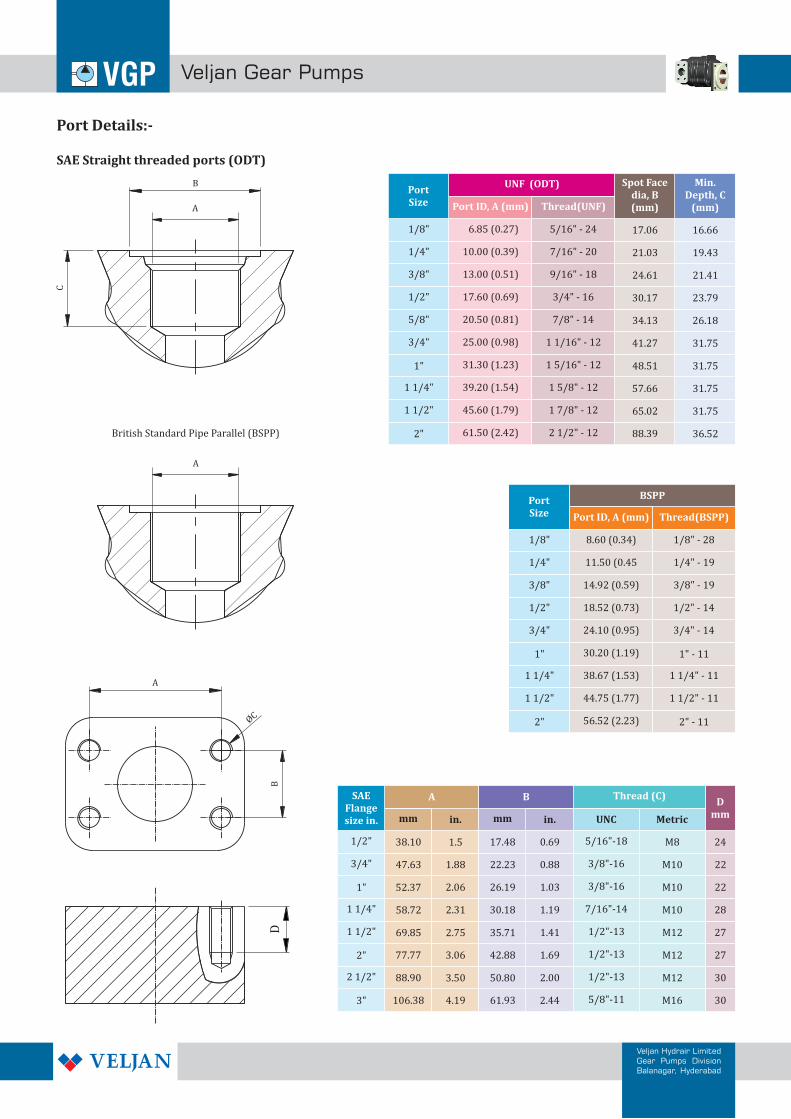
PortSize
BSPP
Port ID, A (mm) Thread(BSPP)
1/8"
1/4"
3/8"
1/2"
3/4"
1"
1 1/4"
1 1/2"
2"
8.60 (0.34)
11.50 (0.45
14.92 (0.59)
18.52 (0.73)
24.10 (0.95)
30.20 (1.19)
38.67 (1.53)
44.75 (1.77)
56.52 (2.23)
1/8" - 28
1/4" - 19
3/8" - 19
1/2" - 14
3/4" - 14
1" - 11
1 1/4" - 11
1 1/2" - 11
2" - 11
SAEFlange size in.
A B Thread (C)
mm in.
38.10 1.5
47.63
52.37
1.88
2.06
58.72 2.31
mm in.
17.48 0.69
22.23
26.19
0.88
1.03
1.1930.18
69.85
77.77
2.75
3.06
88.90 3.50
35.71
42.88
1.41
1.69
2.0050.80
106.38 4.19 2.4461.93
UNC
5/16"-18
3/8"-16
3/8"-16
7/16"-14
1/2"-13
1/2"-13
1/2"-13
5/8"-11
1/2"
3/4"
1"
1 1/4"
1 1/2"
2"
2 1/2"
3"
Metric
M8
M10
M10
M10
M12
M12
M12
M16
Dmm
24
22
22
28
27
27
30
30
Veljan Gear Pumps
Veljan Hydrair LimitedGear Pumps DivisionBalanagar, Hyderabad
6.85 (0.27)
10.00 (0.39)
13.00 (0.51)
17.60 (0.69)
20.50 (0.81)
25.00 (0.98)
31.30 (1.23)
39.20 (1.54)
45.60 (1.79)
61.50 (2.42)
PortSize
UNF (ODT)
Port ID, A (mm) Thread(UNF)
1/8"
1/4"
3/8"
1/2"
5/8"
3/4"
1"
1 1/4"
1 1/2"
2"
5/16" - 24
7/16" - 20
9/16" - 18
3/4" - 16
7/8" - 14
1 1/16" - 12
1 5/16" - 12
1 5/8" - 12
1 7/8" - 12
2 1/2" - 12
Spot Facedia, B (mm)
17.06
21.03
24.61
30.17
34.13
41.27
48.51
57.66
65.02
88.39
Min. Depth, C
(mm)
16.66
19.43
21.41
23.79
26.18
31.75
31.75
31.75
31.75
36.52
A
A
B
ØC
B
C
D
A
British Standard Pipe Parallel (BSPP)
Port Details:-
SAE Straight threaded ports (ODT)
Veljan Gear Pumps
Veljan Hydrair LimitedGear Pumps DivisionBalanagar, Hyderabad
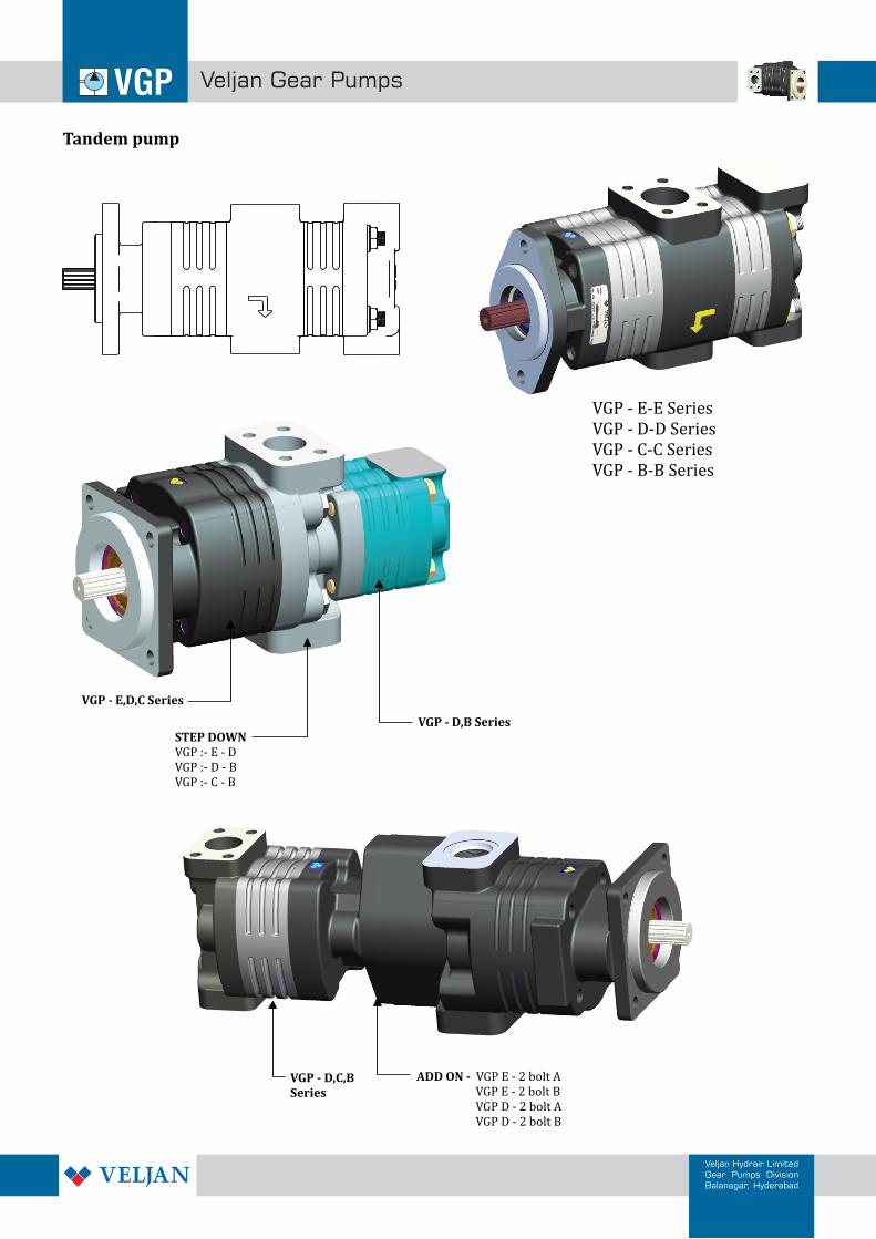
Tandem pump
VGP - E,D,C Series
VGP - D,B SeriesSTEP DOWNVGP :- E - DVGP :- D - BVGP :- C - B
VGP - E-E SeriesVGP - D-D SeriesVGP - C-C SeriesVGP - B-B Series
VGP - D,C,BSeries
ADD ON - VGP E - 2 bolt A VGP E - 2 bolt B VGP D - 2 bolt A VGP D - 2 bolt B