description of proposed in situ experimental set-ups
TRANSCRIPT
Description of proposed in situ experimental set-ups, laboratory experimental set-ups, proposed initial numerical codes and conceptual models
FORGE Report D3.2/D3.3/D3.4– VER.0.1
Name Organisation Signature Date
Compiled Patrik Sellin SKB 3rd Mary 2010
Verified
Approved
Euratom 7th Framework Programme Project: FORGE
FORGE Report: FORGE Report: D3.2/D3.3/D3.4– Ver 0.1
i
Fate of repository gases (FORGE)
The multiple barrier concept is the cornerstone of all proposed schemes for underground disposal of radioactive wastes. The concept invokes a series of barriers, both engineered and natural, between the waste and the surface. Achieving this concept is the primary objective of all disposal programmes, from site appraisal and characterisation to repository design and construction. However, the performance of the repository as a whole (waste, buffer, engineering disturbed zone, host rock), and in particular its gas transport properties, are still poorly understood. Issues still to be adequately examined that relate to understanding basic processes include: dilational versus visco-capillary flow mechanisms; long-term integrity of seals, in particular gas flow along contacts; role of the EDZ as a conduit for preferential flow; laboratory to field up-scaling. Understanding gas generation and migration is thus vital in the quantitative assessment of repositories and is the focus of the research in this integrated, multi-disciplinary project. The FORGE project is a pan-European project with links to international radioactive waste management organisations, regulators and academia, specifically designed to tackle the key research issues associated with the generation and movement of repository gasses. Of particular importance are the long-term performance of bentonite buffers, plastic clays, indurated mudrocks and crystalline formations. Further experimental data are required to reduce uncertainty relating to the quantitative treatment of gas in performance assessment. FORGE will address these issues through a series of laboratory and field-scale experiments, including the development of new methods for up-scaling allowing the optimisation of concepts through detailed scenario analysis. The FORGE partners are committed to training and CPD through a broad portfolio of training opportunities and initiatives which form a significant part of the project.
Further details on the FORGE project and its outcomes can be accessed at www.FORGEproject.org.
Contact details:
Editor: Patrik Sellin
Organisation: SKB
Tel: +4684598522 Fax +46857938611
email: [email protected]
web address: www.skb.se
Address: Box 250, SE-101 24 Stockholm

FORGE Report: D3.2/D3.3/D3.4– Ver 0.1
ii
Contents
Contents ii
Introduction 1
1. Description of proposed in situ experimental set-ups (within URL) 3
2. Description of proposed laboratory experimental set-ups and procedures (bentonite, interface and concrete) 19
3. Description of proposed initial numerical codes and conceptual models 55
References 67
FORGE Report: D3.2/D3.3/D3.4– Ver 0.1
1
Introduction
The current report is a part of the activities in Work Package 3 (WP3) in the FORGE Project.
Gas generation from either the waste form or the engineered barriers is an unavoidable but generally undesired effect in most European repository concepts for radioactive waste. Gas generation and migration can potentially alter the hydraulic and mechanical properties of the repository (possibly the thermal and chemical properties as well). The purpose of WP3 is to investigate gas migration processes and the consequences of gas migration in the EBS of the repositories. The WP will deliver results that can be used for:
• Direct qualitative and quantitative confirmation of the consequences of gas migration to be used in long-term safety assessments;
• Scientific knowledge about the gas migration processes to be used in the development of conceptual models;
• Quantitative data to be used in the development and testing of numerical models for the simulation and prediction of gas migration and its consequences.
The work in this work package is divided into 4 areas:
• Bentonite URL Experiments: Field-scale experiments with bentonite buffers and seals that can be used directly as a confirmation in safety assessment and also give important information on the effects of up-scaling and realistic boundary conditions.
• Bentonite Laboratory Experiment: The tests will complement the URL in the sense that it is possible to investigate the importance of different parameters and processes (materials, boundary conditions, etc) and provide detailed and high quality data to both conceptual and numerical models.
• Interface Laboratory Experiment: Tests that are specifically designed to study the importance of interfaces between different materials or construction parts for the gas migration processes. These tests will supply data to modelling, but also aid in the interpretation of other laboratory and field scale tests.
• Concrete Laboratory Experiments: Tests that are used to study the gas migration process in concrete structures and barriers in the repository. The aim is to study the effects of degree of saturation, gas pressures and alteration of the cement as well as effects of gases on the cementitious materials themselves and provide detailed and high quality data to both conceptual and numerical models.
There is not a separate modelling task within WP 3. Instead the modelling is integrated into the different tasks in three ways:
• Each team is responsible for the interpretation and conceptual modelling of their own experimental work and that will be reported together with the experimental results.
• There is a group for numerical modelling of the experiments integrated in the different tasks. The purpose of the numerical modelling group is to be available to model selected experimental results from the entire WP 3 and will also cooperate with the modelling groups from the other WPs.
FORGE Report: D3.2/D3.3/D3.4– Ver 0.1
2
• Interpretation of the results from experiments/simulations to assess the long term performance of the engineered barriers with respect to gas issues and will serve as input to safety/performance assessment.
WP 3 does also have direct links with all the other work packages.
The current report covers three deliverables from WP3:
3.2 Description of proposed in situ experimental set-ups (within URL)
3.3 Description of proposed laboratory experimental set-ups and procedures (bentonite, interface and concrete)
3.4 Description of proposed initial numerical codes and conceptual models
The purpose of the report is to give a detailed overview of experimental setups as well as capabilities of modelling tools. The target audiences of the report are:
• Internal Work Package participants. The report should serve as a reference guide for the comparison of experimental setups. It should also serve as a guide to the conceptual models used, and identify capabilities, data needs and limitations of the numerical approaches.
• Participants of other work packages. The report should serve as a reference guide for the activities with Work package 3 and will be used as a link between work packages.
At this stage the intention is to keep this report as an internal FORGE document.
The presentation of experimental activities as well as codes and models are done with a FORGE standard template which is common to work packages 3-5.

FORGE Report: D3.2/D3.3/D3.4– Ver 0.1
3
1. Description of proposed in situ experimental set-ups (within URL) - Forge Deliverable 3.2
The current section describes the experimental setups from the activities in WP3 that are undertaken in underground laboratories. These include:
Lasgit (BGS/SKB)
PRACLAY seal test (SCK-CEN)
PGZ (ANDRA)
FORGE Report: D3.2/D3.3/D3.4– Ver 0.1
4
Experimental Systems and Planned Activities
Organisation
British Geological Survey
Work package
WP 3.1.1 LARGE SCALE GAS INJECTION TEST (LASGIT) (BGS & SKB)
Description of planned research
Recent laboratory work has highlighted a number of uncertainties, notably the sensitivity of the gas migration process to experimental boundary conditions and possible scale-dependency of the measured responses. To address these issues a large scale gas injection test (Lasgit) has been initiated at the Äspö Hard Rock Laboratory in Sweden. Lasgit is the first demonstration project designed to study gas migration in bentonite under full-scale repository conditions. The objective of this experimental programme is to provide data to improve process understanding and test/validate modelling approaches, which might be used in performance assessment. Specific objectives are:
(1) perform and interpret a large-scale gas injection test based on the KBS-3 repository design concept,
(2) examine issues relating to up-scaling and its effect on gas movement and buffer performance,
(3) provide additional information on the process of gas migration, and (4) provide high-quality test data to test/validate modelling approaches.
Data from Lasgit will be used by all numerical modelling organisations for a core bench-marking exercise. The main components of this sub-project are:
(a) design and supervision of test programme, (b) compilation and assimilation of the experimental data, (c) interpretation and the development of process understanding, (d) dissemination of project results, (e) operation of the underground activities.
Experimental set-up
A full scale gas injection test has been designed and implemented. It is situated 420 metres below Sea level at the Äspö Hard Rock underground research laboratory (HRL) in Sweden.

FORGE Report: D3.2/D3.3/D3.4– Ver 0.1
5
During deposition, the canister was surrounded with pre-compacted bentonite blocks and the engineering voids filled with bentonite pellets. Once all of the blocks were in place, the deposition hole was capped with a steel lid and secured with 10 Rock anchors, attached through the lid and into the rock. Each anchor was pre-tensioned to 1300 KN force, this was necessary to prevent the canister and bentonite ‘extruding’ from the hole as a result of swelling. As the bentonite becomes saturated it swells to fill any construction gaps and form a seal around the cannister.
As seen in previous studies such as Febex, high water saturations (~95%) are difficult to achieve. Therefore filter mats, placed in strategic positions both within the buffer and on the rockwall have been installed. Water is pumped into the filter mats via 2 sets of reciprocating syringe pumps, theoretically capable of pumping 576 L per day. For gas testing it is possible to isolate individual filter mats and to inject gas.
The deposition hole, buffer and canister are equipped with instrumentation to measure the total stress, porewater pressure and relative humidity in 32, 26 and 7 positions respectively. Additional instrumentation continually monitors variations in temperature, relative displacement of the lid and the restraining forces on the rock anchors.
The state-of-the-art experimental monitoring and control systems for Lasgit are housed in the "Gas Laboratory" which is a self-contained unit designed and assembled by BGS within a modified shipping container. A customised graphical interface based on National Instruments LabVIEWTM software enables remote control and monitoring to be undertaken by project staff from any Internet connected PC around the world.

FORGE Report: D3.2/D3.3/D3.4– Ver 0.1
6
Boundary conditions
The boundary conditions of the experiment are those dictated by the pressures and stresses building up naturally within the buffer during re-hydration. The canister lid has been pre-stressed to 1300 kN as to impose a force comparable with that which would be generated by back-fill within a URL. The experiment is conducted at ambient temperatures.
Measured parameters
Lasgit is a highly instrumented experiment. Directly measured parameters include:
• 5 temperature sensors • pressure in 12 canister filters • pressure in 3 filter mats • stress on the canister in 3 locations (1 axial and 2 radial stress), • displacement of the canister lid and canister in 7 different directions • axial stress on 3 of the rock anchors • pore pressure in 9 intervals within 2 local pressure relief holes (as well as pressure in the
packers) • pressure, volume and flowrate in the 4 ISCO pumps • Stress and temperature within the bentonite at 9 locations • Pore pressure and temperature within the bentonite at 6 locations • Pore pressure and temperature at the rock wall at 20 locations • Stress and temperature at the rock wall at 20 locations • Relative humidy within the bentonite at 7 locations
From these parameters it is possible to calculate:
• Hydration flow rate • Water flow rate (into the system) during hydraulic testing • Gas flow rate (into the system and into the clay) during gas testing • Total volume of water/gas pumped into the system
All parameters are recorded every 15 minutes through the history of the experiment, except for relative humidity which is logged separately.
Test programme
Lasgit was commissioned on the 1st February 2005 and had been running 1461 days by the start of FORGE. In this period there had been 2 years of artificial re-hydration of the bentonite, 1 year of gas-injection testing in filter FL903 with hydraulic constant head testing before and after the gas test, and one further year of artificial hydration.
During the first year of FORGE a detailed gas injection test has been conducted in filter FL903. If time permits, this will be followed by a gas injection test in a different filter. Following the hydraulic head test post-gas injection the system will resume artificial

FORGE Report: D3.2/D3.3/D3.4– Ver 0.1
7
hydration for a period of approximately 1 year. This will be followed by a third programme of gas-injection testing up to the completion of the FORGE project.
Provisional time line
FORGE Year 1: Hydraulic head testing and gas injection within filter FL903
Year 2: Completion of gas injection and possible further injection test in an upper array filter. This will be followed by a further period of artificial hydration
Year 3: Artificial hydration and detailed gas testing
Year 4: Completion of detailed gas testing
FORGE Report: D3.2/D3.3/D3.4– Ver 0.1
8
Experimental Systems and Planned Activities
Organisation
SCK-CEN
Work package
WP 3.1: Engineered Barrier Systems and Seals Bentonite URL experiment-gas migration at host rock/bentonite interface, PRACLAY seal test
Description of planned research/tests
A hydraulic seal has been installed in the PRACLAY gallery in February 2010. The seal is part of the PRACLAY In-Situ Heater Experiment that aims to study the thermo-mechanical-chemical (THM) response of the Boom Clay to both the excavation of a disposal gallery and to a large-scale thermal load.
The hydraulic seal consists of an annular steel structure containing a MX80 bentonite plug resting against the clay. The bentonite will be hydrated whereby its swelling pressure will lower the hydraulic conductivity of the clay in the vicinity of the plug. The seal has a length of 1 m. This is based on scoping calculations, which show that no significant gain is obtained by further increasing the length of the seal.
The principal function of the seal is to create a cut-off barrier to hydraulically isolate the heated section from the rest of the gallery. This cut-off barrier will produce the most conservative conditions in the Boom Clay that can occur in a real repository, independent of the chosen design.
The performance of the seal towards gas breakthrough will be tested as part of this experiment. The test will evaluate how the seal and its surroundings behave during a gas pressure increase. The in situ experimental setup includes four filters installed along the bentonite/Boom clay interface. The gas pressure is progressively increased in one filter. Once breakthrough occurs, the gas pressure will drop. The second filter will act as receiving point to follow possible gas connection. The gas test also includes interpretive modelling by SCK•CEN.
Experimental set-up/description
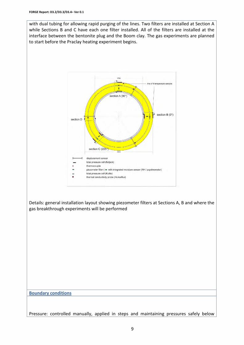
Four filters (90o, 0o and 225o) are installed for the gas experiments. These are all equipped
FORGE Report: D3.2/D3.3/D3.4– Ver 0.1
9
with dual tubing for allowing rapid purging of the lines. Two filters are installed at Section A while Sections B and C have each one filter installed. All of the filters are installed at the interface between the bentonite plug and the Boom clay. The gas experiments are planned to start before the Praclay heating experiment begins.
Details: general installation layout showing piezometer filters at Sections A, B and where the gas breakthrough experiments will be performed
Boundary conditions
Pressure: controlled manually, applied in steps and maintaining pressures safely below
FORGE Report: D3.2/D3.3/D3.4– Ver 0.1
10
swelling pressure in bentonite plug
General parameters for Boom Clay: Hydraulic conductivity: 1.3 - 2.4 10-12 m²/s Total porosity: 36 – 40 % Water content: 19 – 24 % dry wt Stainless steel filters: Porosity: 40% Thickness: 2 mm Diameter: 55 mm seamless Inox 304 Pore size: 5 microns Height: 30 mm
Measured parameters/output from code
Gas breakthrough pressure
Test/modelling programme
In situ tests at interface Boom Clay/bentonite seal
Provisional time line
February 2010: installation 2010-2011: testing after bentonite hydration

FORGE Report: D3.2/D3.3/D3.4– Ver 0.1
11
Experimental Systems and Planned Activities
Organisation
ANDRA
D3.2
Work package
The PGZ experiments are part of an experimental and demonstration test programme at the Meuse/Haute-Marne Underground Research Laboratory.
Description of planned research/modelling work
This short version describes the PGZ2 experiment since the start of equipment installation in the GED programme unit and contributes to the WP3 (deliverable D3.2: Description of the in situ PGZ2 experiment at Bure).
The objectives of PGZ2 are to use gas-injection tests to characterise the gas-transfer properties of seals and interfaces:
• Study of the behaviour of the argillite/clay-based materials interface as regards gas transfer,
• Assessment of the resaturation and swelling behaviour of the plug, as a function of the gas pressure.
The primary objective of Test PGZ2 is to assess the impact of gas on the resaturation and swelling of a plug based on swelling clay. This sealing test in small-diameter boreholes is identified as “Test PGZ2”.
Experimental set-up/code description
A plug will be inserted into a first borehole (PGZ1012). The water resaturation will be done naturally. The objective is to quantify the dynamic of resaturation and the time it requires.
In a second borehole (PGZ1011), a plug is inserted and gas is injected before reaching the full water saturation state full; the injection begins as soon as the clearances around the plug are closed up. The measurements of total pressure and interstitial pressure in the two boreholes will then be compared, to assess the effect of the gas on the plug.
The material selected for the plug is a mixture of MX80-type bentonite and sand, in the proportion of 70% to 30% by weight.
FORGE Report: D3.2/D3.3/D3.4– Ver 0.1
12
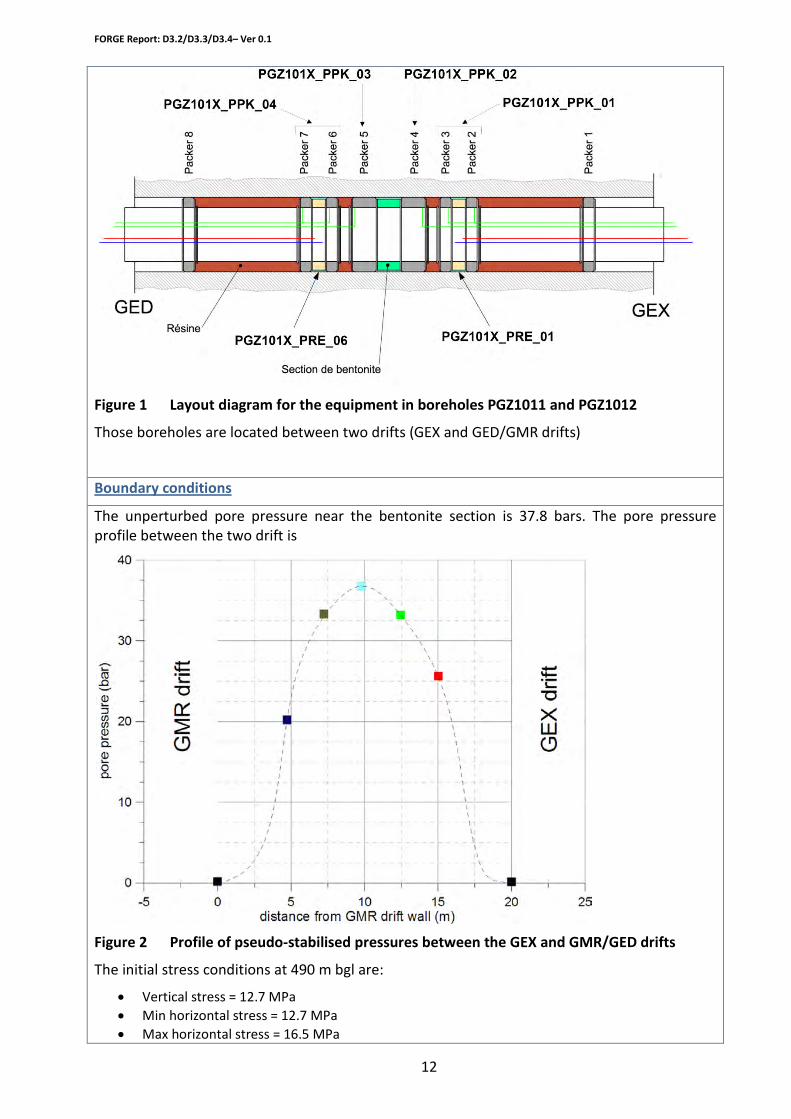
Figure 1 Layout diagram for the equipment in boreholes PGZ1011 and PGZ1012
Those boreholes are located between two drifts (GEX and GED/GMR drifts)
The unperturbed pore pressure near the bentonite section is 37.8 bars. The pore pressure profile between the two drift is
Boundary conditions
Figure 2 Profile of pseudo-stabilised pressures between the GEX and GMR/GED drifts
The initial stress conditions at 490 m bgl are:
• Vertical stress = 12.7 MPa • Min horizontal stress = 12.7 MPa • Max horizontal stress = 16.5 MPa
FORGE Report: D3.2/D3.3/D3.4– Ver 0.1
13
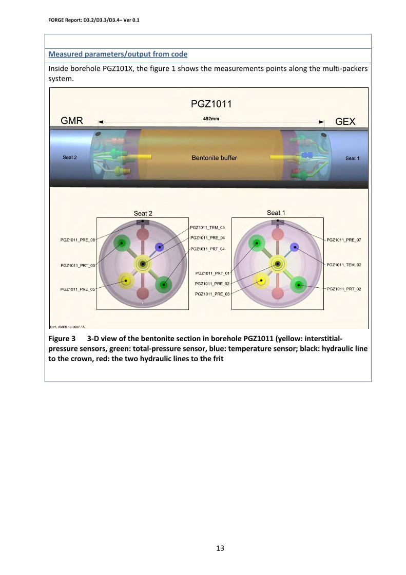
Inside borehole PGZ101X, the figure 1 shows the measurements points along the multi-packers system.
Measured parameters/output from code
Figure 3 3-D view of the bentonite section in borehole PGZ1011 (yellow: interstitial-pressure sensors, green: total-pressure sensor, blue: temperature sensor; black: hydraulic line to the crown, red: the two hydraulic lines to the frit
FORGE Report: D3.2/D3.3/D3.4– Ver 0.1
14
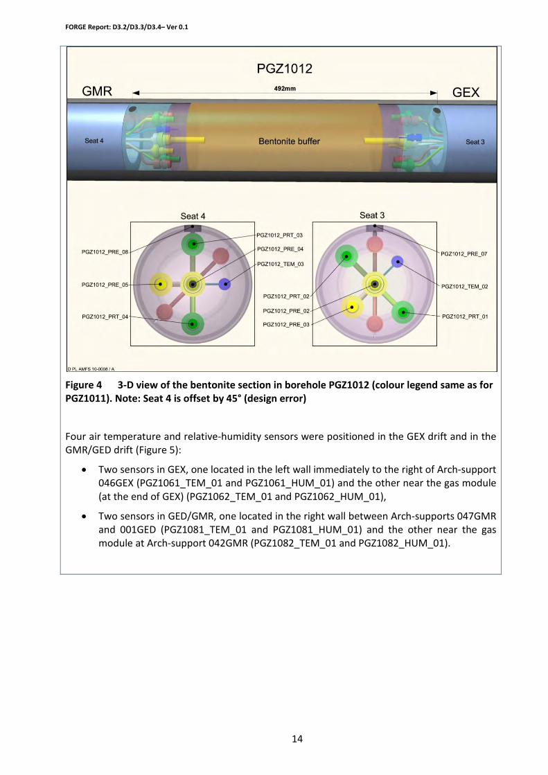
Figure 4 3-D view of the bentonite section in borehole PGZ1012 (colour legend same as for PGZ1011). Note: Seat 4 is offset by 45° (design error)
Four air temperature and relative-humidity sensors were positioned in the GEX drift and in the GMR/GED drift (Figure 5):
• Two sensors in GEX, one located in the left wall immediately to the right of Arch-support 046GEX (PGZ1061_TEM_01 and PGZ1061_HUM_01) and the other near the gas module (at the end of GEX) (PGZ1062_TEM_01 and PGZ1062_HUM_01),
• Two sensors in GED/GMR, one located in the right wall between Arch-supports 047GMR and 001GED (PGZ1081_TEM_01 and PGZ1081_HUM_01) and the other near the gas module at Arch-support 042GMR (PGZ1082_TEM_01 and PGZ1082_HUM_01).
FORGE Report: D3.2/D3.3/D3.4– Ver 0.1
15
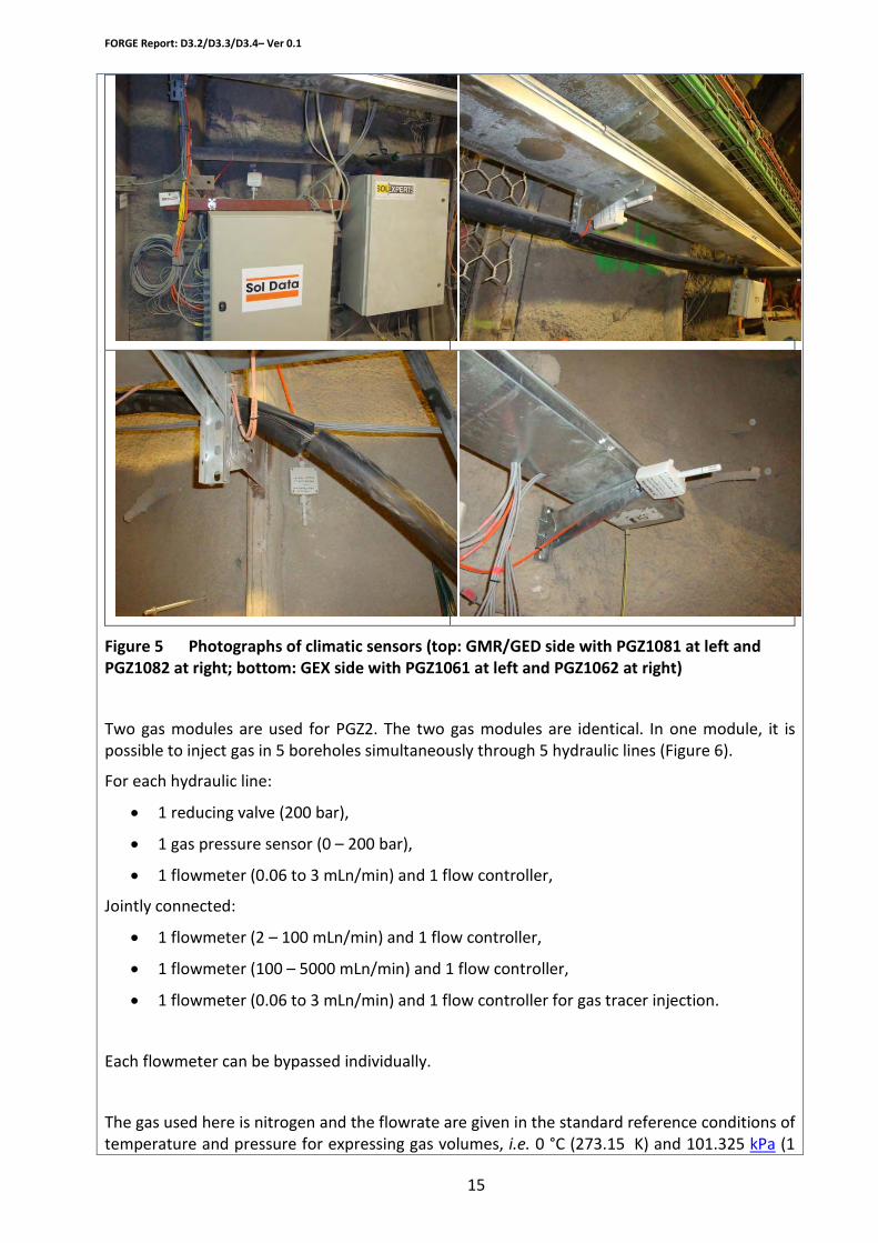
Figure 5 Photographs of climatic sensors (top: GMR/GED side with PGZ1081 at left and PGZ1082 at right; bottom: GEX side with PGZ1061 at left and PGZ1062 at right)
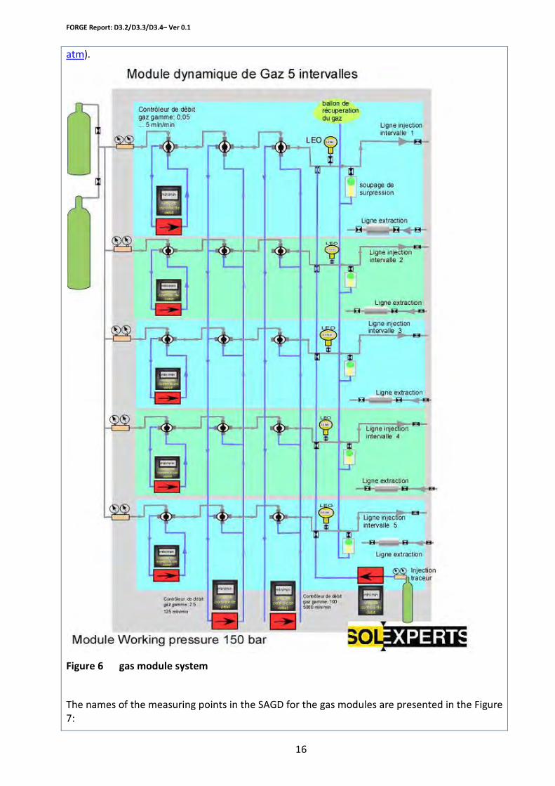
Two gas modules are used for PGZ2. The two gas modules are identical. In one module, it is possible to inject gas in 5 boreholes simultaneously through 5 hydraulic lines (Figure 6).
For each hydraulic line:
• 1 reducing valve (200 bar),
• 1 gas pressure sensor (0 – 200 bar),
• 1 flowmeter (0.06 to 3 mLn/min) and 1 flow controller,
Jointly connected:
• 1 flowmeter (2 – 100 mLn/min) and 1 flow controller,
• 1 flowmeter (100 – 5000 mLn/min) and 1 flow controller,
• 1 flowmeter (0.06 to 3 mLn/min) and 1 flow controller for gas tracer injection.
Each flowmeter can be bypassed individually.
The gas used here is nitrogen and the flowrate are given in the standard reference conditions of temperature and pressure for expressing gas volumes, i.e. 0 °C (273.15 K) and 101.325 kPa (1
FORGE Report: D3.2/D3.3/D3.4– Ver 0.1
16
atm).
Figure 6 gas module system
The names of the measuring points in the SAGD for the gas modules are presented in the Figure 7:

FORGE Report: D3.2/D3.3/D3.4– Ver 0.1
17
Figure 7 Names of the measuring points in the gas modules
PGZ1012
Test/modelling programme
The interstitial and total pressures continue to be monitored in borehole PGZ1012. There are no current plans to carry out gas tests in this borehole.
Following the incident that occurred on one of the packers in borehole PGZ1012 a new borehole (PGZ1013) is planned, designed to monitor the natural resaturation of the bentonite core. This borehole should be drilled and equipped in February 2010. After full resaturation of the core, permeability tests for water and gas will be performed.
¨GZ1011
The start of gas injection was set for November 17, 2009 and the injection programme was modified with respect to the programme proposed in the preliminary report. The constant-pressure gas injection, in parallel on both faces of the core, is retained. However, the injection of gas will be carried out progressively, in stages, so as not to cause mechanical damage to the bentonite core.
The injection programme consists of raising the (nitrogen) gas pressure in successive stages; the injection gas flows are measured continuously. At two pressure stages, a pressure gradient is created, to measure the core's permeability to gas (interference test). The continuation of the gas injection will be adjusted according to the observed responses.
The injection of gas should last 30 to 40 days, after which the development of the system will be monitored.
After full resaturation of the core, its permeability to water and gas will be tested.

FORGE Report: D3.2/D3.3/D3.4– Ver 0.1
18
Provisional time line

FORGE Report: D3.2/D3.3/D3.4– Ver 0.1
19
2. Description of proposed laboratory experimental set-ups and procedures (bentonite, interface and concrete) - Forge Deliverable 3.3
The current section describes the laboratory experimental set-ups and procedures from the activities in WP3. These include:
WP3.2 Fundamental issues (BGS)
WP3.2 Bentonite laboratory experiments (Ciemat)
WP3.3 Interface laboratory experiments: Influence of joints between blocks (Ciemat)
WP3.3 Interface laboratory experiments: Granite/bentonite interface (Ciemat)
WP3.4 Concrete laboratory experiments (Ciemat)
WP3.2 Detailed investigation of gas migration through sand/bentonite (S/B) mixtures (Nagra)
WP3.2 Small scale laboratory gas injection tests to support model development (SKB)
WP3.2 Gas migration at various degrees of saturation (INR)
WP3.3 Transport through interfaces among blocks of sealing materials (IfG)
WP3.3 Gas migration through argillite-bentonite interface (LML)
WP 3.3 Hydrochemical interaction of S/B mixtures with the cementitious tunnel backfill and its potential impact on gas migration (Nagra)
WP3.4 Carbonation reactions of buffer/backfill cements and their impact upon gas and radionuclide migration (BGS)
WP3.4 Gas migration in concrete (SCK-CEN)
FORGE Report: D3.2/D3.3/D3.4– Ver 0.1
20
Experimental Systems and Planned Activities
Organisation
BGS
Work package
WP 3.2 Gas migration in bentonite – fundamental issues (BGS)
The project will be split into two components. The first will comprise a detailed experimental history examining key aspects of the apparent stress memorisation observed within the bentonite (described in below) and its affect on the gas migration behaviour of the clay. Key parameters from this test are the linkage between total stress, porewater pressure and the proportionality factor defined along a complex stress path, the temporal evolution of permeability, gas entry pressure at different water pressures and a critical examination of Lambe’s effective stress law. The second component of the study will focus on the evolution of density in bentonite systems comprised of both intact and pelletised material and will examine their affect on the gas transport behaviour of the system as a whole. The aim of this latter section is to provide quantitative data on gas flow between this interface which can then be used to help interpret the gas injection tests undertaken within Lasgit (WP3.1.1).
Description of planned research/modelling work
There are six main components: (1) a thick-walled stainless steel pressure vessel, (2) a fluid injection system, (3) three independent backpressure systems, (4) five total stress sensors to measure radial and axial stress, (5) a porewater pressure sensor, and (6) a microcomputer-based data acquisition system.
Experimental set-up/code description
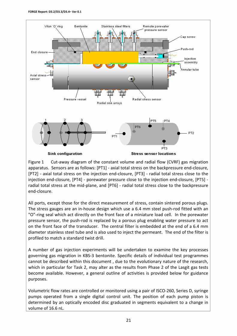
The pressure vessel comprises a dual-closure tubular vessel manufactured from 316 stainless steel and pressure-tested at 69 MPa. Each of the end-closures is secured by twelve high tensile cap-screws which can also be used to apply a small pre-stress to the specimen if required. Figure 1 is a cut-away section showing the two end-closures with their embedded drainage filters and axial total stress sensors, the central fluid injection filter, the twelve radial sink filters, the three radial total stress sensors and the porewater pressure sensor.
FORGE Report: D3.2/D3.3/D3.4– Ver 0.1
21
Figure 1 Cut-away diagram of the constant volume and radial flow (CVRF) gas migration apparatus. Sensors are as follows: [PT1] - axial total stress on the backpressure end-closure, [PT2] - axial total stress on the injection end-closure, [PT3] - radial total stress close to the injection end-closure, [PT4] - porewater pressure close to the injection end-closure, [PT5] - radial total stress at the mid-plane, and [PT6] - radial total stress close to the backpressure end-closure. All ports, except those for the direct measurement of stress, contain sintered porous plugs. The stress gauges are an in-house design which use a 6.4 mm steel push-rod fitted with an "O"-ring seal which act directly on the front face of a miniature load cell. In the porewater pressure sensor, the push-rod is replaced by a porous plug enabling water pressure to act on the front face of the transducer. The central filter is embedded at the end of a 6.4 mm diameter stainless steel tube and is also used to inject the permeant. The end of the filter is profiled to match a standard twist drill. A number of gas injection experiments will be undertaken to examine the key processes governing gas migration in KBS-3 bentonite. Specific details of individual test programmes cannot be described within this document , due to the evolutionary nature of the research, which in particular for Task 2, may alter as the results from Phase 2 of the Lasgit gas tests become available. However, a general outline of activities is provided below for guidance purposes. Volumetric flow rates are controlled or monitored using a pair of ISCO-260, Series D, syringe pumps operated from a single digital control unit. The position of each pump piston is determined by an optically encoded disc graduated in segments equivalent to a change in volume of 16.6 nL.
FORGE Report: D3.2/D3.3/D3.4– Ver 0.1
22
Movement of the pump piston is controlled by a micro-processor which continuously monitors and adjusts the rate of rotation of the encoded disc using a DC-motor connected to the piston assembly via a geared worm drive. Pressure and flow rate of test fluid is controlled by a number of syringe pumps. A programme written in LabVIEWTM elicits data from the pump and load-cells at pre-set time intervals. Testing is performed in an air-conditioned laboratory at a nominal temperature of 20 ºC.
Tests will be perform in a thick-walled pressure vessel (described above) imposing a constant volume boundary condition. External porewater pressure will be continuously controlled during each experiment.
Boundary conditions
The test will measure the hydraulic and gas transport properties of bentonite subject to different porewater pressure regimes (Task 1) and density variations within the start material (Task 2) . A detailed description of the tasks and expected results can be found in the following section.
Measured parameters/output from code
Task 1: Stress/porewater coupling and its affect on gas migration Test/modelling programme
This test will be performed using a high-pressure version of the apparatus described in Harrington and Birchall (2007). Stress instrumentation will be changed in order to improve accuracy (given the extended pressure range of the apparatus) and to remove any possible of a system artefact as a cause for the earlier reported results.
(a) The intrinsic permeability of the clay will be measured longitudinally along the major axis of the specimen. Each radial filter array will be connected to a separate pressure transmitters which will yield information on the porewater distribution long the specimen and provide a mechanism for examining the validity of Darcy’s law within the clay.
(b) Backpressure will then be incremented and decremented in a series of steps while total stress (axial and radial) and porewater pressure (external and internal) are continuously monitored at a number of locations on the specimen. The hydraulic gradient across the specimen will be maintained during these test stages.
(c) Gas injection. a. Option 1: To examine the affect of stress memorisation on the clay caused by the previous hydraulic loading, a detailed gas injection test will be performed to quantify changes in gas entry, migration and sealing processes within the clay subject to its original (start) water pressure. b. Option 2: To examine the change in gas entry pressure as a function of externally applied water pressure, a detailed gas injection test will be performed at the maximum value of externally applied water. Once complete, porewater pressure will be reduced to the original start value and a second gas injection test performed as outlined in Option 1. However, it should be noted that superposition of results may be an issue for the latter gas test which may not yield representative results compared to those obtained from true virgin material.
A decision on which option to follow will be made closer to the time following consultation with SKB. Task 2: Stress/density homogenisation of the clay and its affect on gas flow

FORGE Report: D3.2/D3.3/D3.4– Ver 0.1
23
It is likely that this test will be performed in a similar apparatus to that used above to facilitate the simultaneous measurement of total stress and porewater pressure during the hydration of the different bentonite components and the subsequent gas injection tests performed in each.
(a) Upon assembly of the apparatus, the clay will be hydrated and the resultant swelling pressure independently measured within the block and pelletised material.
(b) The intrinsic permeability for each will then be determined in order to look for significances in the hydraulic properties of the clay and then link these to the measured swelling pressure.
(c) Two detailed gas injection histories will then be undertaken, one in each system component, to investigate the conditions under which gas becomes mobile with the clay. This will provide quantitative data on the gas entry pressure for both clays and any difference in the ay in which gas can move within each system component including the non-linearity associated with the gas flow law and the capacity of the clay to self seal subject to low gas pressure gradients.
The content of each test stage will be defined nearer the time to reflect, where appropriate, new results from the Lasgit and FORGE studies.
D4.1: Description of the experimental set-up: March 2010 Provisional time line
Preliminary timeline: Task 1 March 2010 to August 2011. Test 2 August 2011 to December 2012. Additional tests will be performed if time permits.

FORGE Report: D3.2/D3.3/D3.4– Ver 0.1
24
Experimental Systems and Planned Activities
CIEMAT Organisation
WP3.2 Bentonite laboratory experiments Work package
WP3.3 Interface laboratory experiments: Influence of joints between blocks WP3.3 Interface laboratory experiments: Granite/bentonite interface WP3.4 Concrete laboratory experiments
WP3.2 Bentonite laboratory experiments: A set of gas transport tests will be performed on compacted FEBEX bentonite to determine the gas permeability and breakthrough pressure as a function of degree of saturation and confining pressure.
Description of planned research
WP3.3 Influence of joints between blocks: Gas permeability and breakthrough tests will be performed in bentonite blocks with a central joint that will be previously saturated. WP3.3 Granite/bentonite interface: Laboratory tests for studying the flow of gas through the granite/bentonite interface once the bentonite is completely saturated. WP3.4 Concrete laboratory experiments: Gas permeability measurements will be performed in concrete samples of different degrees of saturation under low gas pressure. To analyse the unsaturated flow, columns of concrete instrumented with sensors will be infiltrated or desiccated.
• Non-steady state gas permeability equipment (Figure 1): The cylindrical sample is placed in a pressurised triaxial cell. The inlet at the lower part of the sample is connected to an airtight tank of known volume, in which nitrogen gas is previously injected at a pressure slightly higher than atmospheric. The inlet at the upper part of the sample is left open to the atmosphere. The test consists in allowing the air in the tank to exit to the atmosphere across the specimen, while the decrease in pressure in the tank is measured versus time. Permeability can be computed from the pressure decrease in a manner analogous to that used for the expression of permeability to water using a falling head permeameter.
Experimental set-up
Figure 8: Schematic representation of the gas permeability measuring system

FORGE Report: D3.2/D3.3/D3.4– Ver 0.1
25
• Steady state gas permeability equipment (Figure 3): The setup has been designed to perform steady gas permeability measurements under different gas pressures. The cylindrical sample –with or without a central joint– is confined in a triaxial cell. The injection and downstream pressures can be independently varied and kept constant during the period of time necessary to get steady flow. Different range flowmeters measure the inward and outward flows. The equipment works like a constant head permeameter, with the possibility to change the head value and measure the gas flow value. The system applies the pressures to the sample and registers flow and pressures from the measurement devices. In and outflow gas rates, up and downstream pressure, and the confining pressure are monitored. To compute the permeability the inflow or outflow measurements can be used, applying an equation for incompressible media with compressible pore fluids.
Figure 9: Schematic diagram of the setup for the gas permeability tests
• Evaporation tests (Figure 4): Cylindrical concrete samples confined in a PVC mold will be submitted to evaporation (or infiltration) through their top surface, while relative humidity and temperature are measured at different levels along the column and the mass change is recorded. The back-analysis of this information allows computing the unsaturated permeability.
Figure 10: Setup for the evaporation tests in concrete
FORGE Report: D3.2/D3.3/D3.4– Ver 0.1
26
Tests in the non-steady state gas permeability equipment: Boundary conditions
• Confining pressure high enough to avoid peripheral pathways without causing consolidation of the specimen.
• The downstream pressure will be kept atmospheric.
• Gas injection pressure will decrease during the test from an initial value of 1.03 MPa.
• Zero vertical displacement.
• Effective tension on the sample: variable and known.
• The tests will be performed at room temperature.
Tests in the steady state gas permeability equipment:
• Confining pressure high enough to avoid peripheral paths. In other tests the sample will be laterally confined with a rigid jacket.
• The downstream pressure will be kept constant.
• Gas injection pressure will be varied by steps.
• Zero vertical displacement.
• Zero lateral strain when a rigid jacket is used.
• Effective tension on the sample: variable and known, except if a rigid jacket is used.
• The tests will be performed at room temperature
Tests in the non-steady state gas permeability equipment: Measured parameters
• Confining pressure.
• Gas pressure upstream.
• Estimation of the gas permeability from the pressure decrease in the upstream deposit.
• Final density and water content of the material.
Tests in the steady state gas permeability equipment:
• Confining pressure.
• Gas flow in and out the cores.
• Gas pressure upstream and downstream.
• Estimation of permeability under gas stable flow conditions, corresponding to the pressure step in which the gas breakthrough is produced and subsequent steps. Also, the deduction of the possible generation of preferential paths.
• Final density and water content of the material.
Evaporation/infiltration tests:
• Relative humidity and temperature inside concrete.
• Relative humidity and temperature above the evaporation surface.
• Concrete mass change.
FORGE Report: D3.2/D3.3/D3.4– Ver 0.1
27
The clay samples will be compacted to different dry densities and water contents. The dry densities will be in the range 1.4 to 1.7 g/cm3, and the water contents from 5 to 20 percent, depending on the dry density.
Test programme
Tests in the non-steady state gas permeability equipment: The tests will be performed with a confining pressure of 0.6 MPa, and the pressure in the tank will be initially 1.03 MPa in all the cases. This method does not allow the measurement of very low permeabilities, and hence it will not be used in samples with a very high degree of saturation, but just as a backup for the measurements performed with the other setup. Tests in the steady state gas permeability equipment: Two types of experimental procedures are foreseen as a function of the expected gas permeability:
• Medium-low permeability samples: The injection and confining pressures will be progressively increased and permeability will be computed from the outflow once it is steady.
• Fracture or breakthrough in low permeability samples: The injection pressure will be increased stepwise, until reaching the breakthrough value. Accordingly, confining pressure must be also increased at the same rate (except if a rigid jacket is used). After breakthrough occurs, the gas pressure paths will be closed for 24 hours, and afterwards the procedure described above will be repeated, in order to determine the possible development of preferential paths which could reduce the value of the gas breakthrough pressure.
WP3.2 Bentonite laboratory experiments: Systematic measurements will start in the first semester of 2010.
Provisional time line
WP3.3 Influence of joints between blocks: This task will start along 2010, the exact date depending on the preliminary results. WP3.3 Granite/bentonite interface: This task will start along 2010, the exact date depending on the preliminary results. WP3.4 Concrete laboratory experiments: These have already started and will go on until the end of 2010.

FORGE Report: D3.2/D3.3/D3.4– Ver 0.1
28
Experimental Systems and Planned Activities
Organisation
NAGRA: Nationale Genossenschaft für die Lagerung radioaktiver Abfälle
Hardstrasse 73 Nagra
5430 Wettingen Switzerland Tel.: +41 (0)56 437 11 11 Contact: Dr Joerg Ruedi
WP3.2 Detailed investigation of gas migration through sand/bentonite (S/B) mixtures Work package
The large S/B column experiment at Grimsel Test Site (GTS) aims at providing detailed datasets over long times and larger scale (dm) than normal laboratory experiments to validate the models applied to predict the saturation and water transport in S/B mixtures. A later gas injection test aims at assessing the gas entry pressure of highly compacted S/B mixtures.
Description of planned research/modelling work
The experiment was setup in 2002 and it is foreseen to run at least until the end of the FORGE project. A number of modelling exercises were performed in the past to explain the experimental results (see NAB07-39).
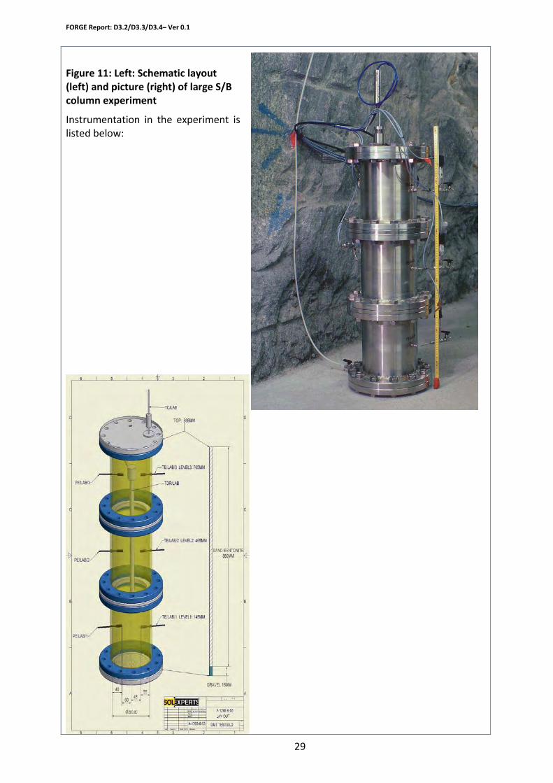
The experimental layout is shown in Figure 8. The external casing is made of stainless steel with an inner diameter of 200 mm. The casing has been designed, constructed, and tested, for a maximum internal pressure of 20 bar.
Experimental set-up/code description
FORGE Report: D3.2/D3.3/D3.4– Ver 0.1
29
Figure 11: Left: Schematic layout (left) and picture (right) of large S/B column experiment
Instrumentation in the experiment is listed below:

FORGE Report: D3.2/D3.3/D3.4– Ver 0.1
30
Column instrumentation
Instrument Count Measurement Piezometers 3 Pore pressure and suction (initially) TDRs 1 Volumetric water content (average on full
length) Total pressure cell 1 Load on the container Water/gas injection/extraction systems Instrument Count Measurement Piezometers 2 Water/gas pressure Differential pressure sensor 1 Delta-p at water extraction side (to
determine water flow) Water column flow meter 1 Water flow at water injection side
The experiment is run under constant temperature conditions (at Grimsel Test Site, about 14 °C). Water injection was done stepwise at constant pressures up to 20bar. Dissolved gas concentration in injection water was according to the water pressure (i.e. gas on top of injected water). On the extraction side an additional volume was be added in 2009 to control the water pressure at the column outlet (before outflow at 1 atm)
Boundary conditions
• Water and gas pressure / suction
Measured parameters/output from code
• Water saturation (average) • Total pressure • Water and gas in and outflow
Response to saturation, hydraulic testing and gas injection Fluorescent tracer was added to the injection water to provide more detailed evidence on water transport in the column.
The following experimental activities are planned within the FORGE project Test/modelling programme
• Continue saturation • Ev. gas injection test starting 2010
Provisional time line
FORGE Report: D3.2/D3.3/D3.4– Ver 0.1
31
Experimental Systems and Planned Activities
Organisation
SKB (Clay Technology)
WP 3.2
Work package
Small scale laboratory gas injection tests to support model development
Description of planned research/modelling work
Small scale (cm) gas injection test will be performed on saturated bentonite in constant volume cells. The tests will be conducted in conjunction with the development of a model for gas migration in compacted bentonite.
Experimental set-up/code description
The tests are suggested to be performed in stages of increasing complexity. Before performing actual gas breakthrough tests, it is of importance to learn how the swelling pressure responds to an applied gas or water pressure. In a initial stage it is also important to establish where gas paths are formed during migration.
By making the test samples small, the time for water saturation will in turn be short and many tests could be performed. Hence statistical knowledge of the processes will be gained.
Below is listed a suggested set of tests to be performed in order. The design and choices made for later tests could be changed dependent on the outcome of the earlier ones.
A. “Generalized hydraulic conductivity” measurements
In a first series of test the total pressure response (PT) and fluid flux is measured as a function of a pressure gradient across a clay sample. The applied pressure is either due to water (Pl) or gas (Pg). The test geometry is circular symmetric:

FORGE Report: D3.2/D3.3/D3.4– Ver 0.1
32
These tests give knowledge of the difference in total pressure response due to external water pressure or external gas pressure. Such knowledge is crucial in order to draw correct conclusions from gas migration experiments. The “generalized hydraulic conductivity” measurements also give information for validation/modification/rejection of the conceptual view.
B. Preferential path detection
In order to determine whether preferential paths are formed between the clay and the sample holder the following test set-up is suggested (arrows indicate possible gas paths):
A gas pressure is applied to the bottom filter. Gas detection is made in the other filters. By varying the sample geometry (filter sizes, sample length/height, clay density, etc.) the question if and when preferential paths are developed can be answered.
C. Pressure threshold for gas break-through
When a set-up which allows gas migration path through the clay sample has been established, the pressure threshold for gas break-through will be investigated using the same type of set-up as in B. These tests will both test the conceptual model as well as provide material characterization.
D. Statistical characterization of migration path
In order to investigate the gas migration process further, spatial resolution could be obtained by including one or several filter rings on the outlet side:
Applied Pg or Pl
Measured fluid flux(water, diffused gas)
Measured PT
Clay sample(Bentonite, montmorillonite,)
Filter
Any preferential path betweensample and container will be detected here
Any path penetrating thesample will be detected here
dF
Measured PT

FORGE Report: D3.2/D3.3/D3.4– Ver 0.1
33
In these tests the dependence of the gas migration process on several variables can be observed, e.g sample length/height ration, sample density, time dependency on the applied gas pressure etc.
Boundary conditions
The primary material choices will be (but other selections could be made, dependent on the outcome of the tests)
• MX-80 bentonite • Na-montmorillonite • Ca-montmorillonite.
Water/Gas pressures at the inlet/outlet will be controlled (see above)
Measured parameters/output from code
In all tests: Total Pressure (PT) response.
In set-up A: Water flux, Hydraulic conductivity will be deduced
In set-up B,C and D: Gas flux, and its localization
Se above.
Test/modelling programme
Provisional time line
The major part of the work will be performed under 2010
Spatial resolutionof gas flow
filter ring
Measured PT
Applied Pg
FORGE Report: D3.2/D3.3/D3.4– Ver 0.1
34
Experimental Systems and Planned Activities
Organisation
Institute for Nuclear Research, Pitesti, Romania
Work package
WP3
The research aims to investigate the processes occurring during the gas migration through near saturated and saturated compacted bentonite correlating experimental data of a gas breakthrough, internal stress evolution in the sample and its microstructural characteristics. In this regards, following steps have been foreseen:
Description of planned research/modelling work
Capillary pressure assessment - experiments and correlation with micro-porosity characteristics, matric
potential. Gas migration experiments in compacted bentonite (He, H2)
– Saturation degree: 0.7 – 1 – Temperature range: 25-50oC
Gas breakthrough mechanisms investigation using appropriate instrumentation
– i.e. pressure gages
1. For swelling – shrinkage tests the experimental set-up consists in a typical oedometer Experimental set-up/code description
2. For gas migration the experimental set-up for gas migration investigation consists in a 40 MPa pressure vessel and associated confining pressure system, fluid injection system, back pressure system and microcomputer-based data acquisition system. The bentonite sample will be placed between sintered stainless steel discs in a 18mm thick stainless steel holder. The bentonite sample is consolidated by simultaneously applying a confining pressure and a backpressure of 1MPa. The gas and water injection will be controlled by two syringe pumps. The gas injection pressure, the water pressure and the confining pressure are monitored by pressure transmitters linked to digital pressure indicators. The syringe pump controller allows volume, flow rate and pressure data to be transmitted to the equivalent port of the logging microcomputer.

FORGE Report: D3.2/D3.3/D3.4– Ver 0.1
35
Boundary conditions
Constant volume backpressure =1MPa confining pressure – to be determined depending on the swelling pressure value
Measured parameters/output from code
1. dry density 2. porosity distribution of compacted bentonite at different saturation degrees 3. capillary pressure estimation 4. swelling pressure 5. gas intrinsic permeability 6. hydraulic conductivity at saturation 7. breakthrough pressure curves for H2 and an inert gas 8. internal stress during the pressure test
Test/modelling programme
1. Bentonite characterization of from different locations in Romania 2. Swelling tests on bentonite compacted at optimum water content: - strain swelling curves under a 5KN/m2 load - strain swelling curves under loadings between 5 and 800 KN/m2 followed by sample
decompression - swelling pressure calculation 3. Gas migration tests: 3.1. gas migration in near saturation conditions
- bentonite compaction at optimum water content - saturation at different saturation degrees (0.75, 0.90) - gas breakthrough test
FORGE Report: D3.2/D3.3/D3.4– Ver 0.1
36
3.2. inert gas migration at saturation, 25oC - bentonite compaction at optimum water content
- full saturation, permeability measurement - gas injection - gas, pressure, breakthrough pressure and internal stress recording 3.3. Inert gas migration at saturation, 40oC
- bentonite compaction at optimum water content - full saturation, permeability measurement - gas injection - gas, pressure, breakthrough pressure and internal stress recording 3.4. H2 migration at saturation, 25oC
- bentonite compaction at optimum water content - full saturation, permeability measurement - gas injection - gas, pressure, breakthrough pressure and internal stress recording
1. Bentonite characterization: – April 30, 2010 Provisional time line
2. Swelling tests: – July 30, 2010 3. Gas migration tests: 3.1. Gas migration in near saturation conditions – March 30, 2011 3.2. Inert gas migration at saturation, 25oC – September 30, 2011 3.3. Inert gas migration at saturation, 40oC – April 30, 2012 3.4. H2 migration at saturation, 25oC – December 31, 2012 4. Correlation of the experimental data – January 31, 2013
FORGE Report: D3.2/D3.3/D3.4– Ver 0.1
37
Experimental Systems and Planned Activities
Institut für Gebirgsmechanik (IfG Organisation
Friederikenstr. 60 D-04279 Leipzig Germany Contact persons: Till Popp ([email protected]); Klaus Salzer ([email protected])
WP3.3.1 Transport through interfaces among blocks of sealing materials (IfG) Work package
Knowledge of gas transport properties through sealing or buffer materials is independently from the respective radioactive waste repository concept of vital importance for long term performance assessments because some gas generation may take place as a consequence of different processes (for instance corrosion of iron and degradation of organic materials).
Description of planned research/modelling work
Laboratory test results are important to deduce the hydro-mechanical (HM) parameters for numerical calculations evaluating the long term integrity of EBS. The lab investigations of IfG are aiming (1) on interfaces between bentonite bricks itself and (2) on mechanical contacts of bentonite blocks and concrete to various host rocks, i.e. indurated clay or granite. The main objectives of the laboratory work are twofold :
1. to investigate gas transport properties of interfaces between bentonite blocks. The sub topics are:
o to perform long term laboratory tests (duration of several month up to two years) on artificial contact interfaces between sealing material bricks (i.e. bentonite) and to the host rock under well controlled stress and swelling conditions with water injection resp. subsequent gas injection,
o to provide data for time dependent interface “permeability” changes (i.e. sealing) during long term compaction and fluid injection,
o to provide data about gas entry pressures and relative gas permeability changes during pressure dependent gas injection.
2. to provide experimental data from short term tests in a direct shear apparatus with measuring of gas transport and mechanical contact properties for the various interface configurations undergoing shear deformation at defined normal stresses.
The “shear failure” of a sealing plug due to fluid pressurisation or swelling phenomena is governed by hydro-mechanical characteristics of the confined plug / host rock interface. If shear slip occurs on a critically stressed interface, it can raise the permeability of the fracture through several mechanisms, including brecciation, surface roughness, and breakdown of seals (Barton et al., 1995). However, increased pore pressures acting in
FORGE Report: D3.2/D3.3/D3.4– Ver 0.1
38
the interface may also lower the acting minimal stress, thus initiating the shear failure.
Moreover, it has been shown by Buzzi et al. (2006) that bentonite is very sensitive to hydraulic erosion, producing flow channels within the interface zone.
In the last step of investigation the numerical code UDEC (Universal Distinct Element Code) of ITASCA is used for analysis of the observed coupled hydro-mechanical properties of buffer interfaces based on the experimental results.
Two experimental setups will be used for measuring fluid transport properties through the buffer respectively along the interface between block contacts, i.e. buffer/buffer and buffer/block at defined interface conditions:
Experimental set-up/code description
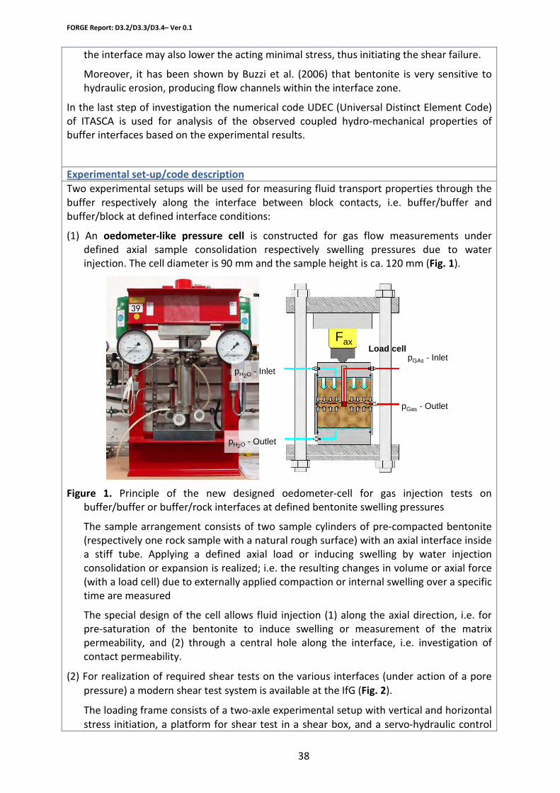
(1) An oedometer-like pressure cell is constructed for gas flow measurements under defined axial sample consolidation respectively swelling pressures due to water injection. The cell diameter is 90 mm and the sample height is ca. 120 mm (Fig. 1).
Figure 1. Principle of the new designed oedometer-cell for gas injection tests on buffer/buffer or buffer/rock interfaces at defined bentonite swelling pressures
The sample arrangement consists of two sample cylinders of pre-compacted bentonite (respectively one rock sample with a natural rough surface) with an axial interface inside a stiff tube. Applying a defined axial load or inducing swelling by water injection consolidation or expansion is realized; i.e. the resulting changes in volume or axial force (with a load cell) due to externally applied compaction or internal swelling over a specific time are measured
The special design of the cell allows fluid injection (1) along the axial direction, i.e. for pre-saturation of the bentonite to induce swelling or measurement of the matrix permeability, and (2) through a central hole along the interface, i.e. investigation of contact permeability.
(2) For realization of required shear tests on the various interfaces (under action of a pore pressure) a modern shear test system is available at the IfG (Fig. 2).
The loading frame consists of a two-axle experimental setup with vertical and horizontal stress initiation, a platform for shear test in a shear box, and a servo-hydraulic control
pGAs - Inlet
pGas - Outlet
pH2O - Inlet
pH2O - Outlet
FaxLoad cell

FORGE Report: D3.2/D3.3/D3.4– Ver 0.1
39
unit for two channels (vertical and horizontal). Both can be managed force or displacement controlled. The frontal part (right) is an extremely stiff four-columned test frame for fixing and vertical loading of the two-part shear box by the upper hydraulic cylinder (up to 500 kN axial load).
Horizontal motion is guided by a precision linear bearing, which is designed for low friction and a single degree of freedom (translation only). The horizontal force is generated by a laterally positioned horizontal cylinder (- 250 kN pressure; - 160kN tension). The upper part of the shear box is fixed by a horizontal housing that enables yet a twisting of approx. 2° around the horizontal axes referring to the shear midpoint. While a vertical load acts to the whole shear box the lower box can be horizontally displaced under load.
Figure 2. The MTS – shear test system (model 816), available at the IfG.
The LVDT’s are positioned at the initial specimen joint shear plane in multiple locations (4 vertical and 2 horizontal LVDT) which guarantees that the dilatancy, the shear displacement and the rotations can accurately be measured.
A sufficiently stiff fixing of the specimens is a prerequisite for an exact determination of shear resistance. Therefore, first of all the specimen is orientated in a position where the line of action of the shear force (τT) is on the investigated interface and the line of action of the normal stress (σn) is perpendicularly to that plane. Consequently both shear boxes will be filled in succession with high-strength anchor cement mortar. Thereby a defined opening of around 5 to 20 mm remains that enables the shear test of the fixed specimen.
Pore fluid pressures are applied through a central bore hole similar to that which is used in the oedometer cell (see Fig. 1). The final test equipment is under construction.
Two gas injection procedures will be applied to determine the gas threshold pressure and the gas permeability at various compaction- and hydration-stages:
a) In constant pressure gas testing, the injection pressure of the gas is raised in a series of steps until gas entry occurs. Subsequent steps in gas pressure are used to define the gas permeability function.
b) In constant flow rate tests, the gas is pumped into the upstream reservoir of the

FORGE Report: D3.2/D3.3/D3.4– Ver 0.1
40
injection system, gradually raising its pressure until it overcomes the resistance for flow within the laboratory specimen. Once gas movement within a specimen occurs, flow rate into the injection system can be varied to examine the transport characteristics of the material, thereby defining the permeability function.
Main advantages of UDEC for simulating HM-properties of Block masonries • Possibility of simulation of coupled HM-behaviour of interfaces • Simulation of displacements (slip and opening) in both the normal and shear
directions along surfaces (buffer / buffer or buffer / block) in a bentonite block masonry
• Various conceptional approaches for the description mechanical interface properties (e.g., Coulomb slip, Minkley-model)
Depending on the various drift sealing concepts the used buffer materials show a wide spectrum of hydro-mechanical properties, e.g. strength and stiffness of the pre-compacted blocks. However, most of the experiments will be performed with pre-compacted Wetro FS40 bentonite bricks, which were manufactured and tested in the so-called drift-sealing project in the salt mine Sondershausen (D) (for details see Sitz, 2003). The relevant material properties of the bricks are, as follows:
Boundary conditions
• Compression force: 40 – 50 MPa • Dimensions: 25 x 12.5 x 6.25 cm3 • Composition: ca. 60% bentonite (Calcigel) + 40% sand • Water-content (%) 7.5±0.5 • Compressed density (g/cm3) 2.27±0.01 • Bentonite dry density (g/cm3) 1.89±0.02 • Initial saturation (-) 0.77±0.04 • Hydraulic conductivity with NaCl-brine (m/s) ca. 10-12 • Swelling pressure (MPa) - NaCl 3.5
It has to be mentioned that the swelling pressure will be significantly higher if water is injected instead of NaCl-brine. In the actual state it is fore seen to use artificially fractured granite cores as reference surface for simulating contact interfaces between the bentonite block and the host rock. As experimental random condition for the “oedometer” tests the sample volume should remain constant during saturation, which will result in the development of swelling pressure. Because only in axial direction the swelling pressure can be measured via a load cell (see Fig. 1), whereby the stress conditions inside the buffer are assumed to be isotropic. However, it has to be mentioned, that effects of friction at the contact sample/steel tube surface have to be considered. , i.e.
Hydraulical parameters of interfaces Measured parameters/output from code
• Intrinsic permeability of buffer matrix (initial state) respectively of the interface.
• Development of gas permeability as a function of normal stress on the interface and saturation.
• Capillary entry pressure of gas into the (partially) saturated buffer matrix, i.e. the pore fluid pressure for which gas flow initiates. Below this pressure, the rock behaves impermeably for gas.
FORGE Report: D3.2/D3.3/D3.4– Ver 0.1
41
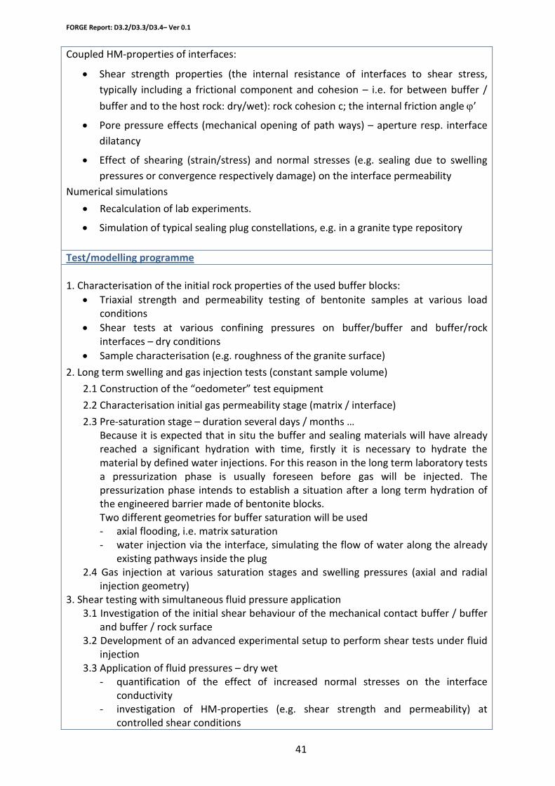
Coupled HM-properties of interfaces:
• Shear strength properties (the internal resistance of interfaces to shear stress, typically including a frictional component and cohesion – i.e. for between buffer /
buffer and to the host rock: dry/wet): rock cohesion c; the internal friction angle ϕ’
• Pore pressure effects (mechanical opening of path ways) – aperture resp. interface dilatancy
• Effect of shearing (strain/stress) and normal stresses (e.g. sealing due to swelling pressures or convergence respectively damage) on the interface permeability
Numerical simulations
• Recalculation of lab experiments.
• Simulation of typical sealing plug constellations, e.g. in a granite type repository
Test/modelling programme
1. Characterisation of the initial rock properties of the used buffer blocks: • Triaxial strength and permeability testing of bentonite samples at various load
conditions • Shear tests at various confining pressures on buffer/buffer and buffer/rock
interfaces – dry conditions • Sample characterisation (e.g. roughness of the granite surface)
2. Long term swelling and gas injection tests (constant sample volume)
2.1 Construction of the “oedometer” test equipment
2.2 Characterisation initial gas permeability stage (matrix / interface)
2.3 Pre-saturation stage – duration several days / months … Because it is expected that in situ the buffer and sealing materials will have already reached a significant hydration with time, firstly it is necessary to hydrate the material by defined water injections. For this reason in the long term laboratory tests a pressurization phase is usually foreseen before gas will be injected. The pressurization phase intends to establish a situation after a long term hydration of the engineered barrier made of bentonite blocks. Two different geometries for buffer saturation will be used - axial flooding, i.e. matrix saturation - water injection via the interface, simulating the flow of water along the already
existing pathways inside the plug 2.4 Gas injection at various saturation stages and swelling pressures (axial and radial
injection geometry) 3. Shear testing with simultaneous fluid pressure application
3.1 Investigation of the initial shear behaviour of the mechanical contact buffer / buffer and buffer / rock surface
3.2 Development of an advanced experimental setup to perform shear tests under fluid injection
3.3 Application of fluid pressures – dry wet - quantification of the effect of increased normal stresses on the interface
conductivity - investigation of HM-properties (e.g. shear strength and permeability) at
controlled shear conditions
FORGE Report: D3.2/D3.3/D3.4– Ver 0.1
42
4. Numerical analysis of the interface properties by simulation of typical sealing plug constellation based on the measured HM-properties
- Recalculation of lab experiments. - Simulation of typical sealing plug constellations, e.g. in a granite type repository
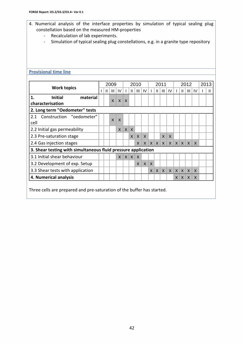
Provisional time line
Work topics 2009 2010 2011 2012 2013
I II III IV I II III IV I II III IV I II III IV I II 1. Initial material characterisation
x x x
2. Long term "Oedometer" tests 2.1 Construction “oedometer” cell
x x
2.2 Initial gas permeability x x x 2.3 Pre-saturation stage x x x x x 2.4 Gas injection stages x x x x x x x x x x 3. Shear testing with simultaneous fluid pressure application 3.1 Initial shear behaviour x x x x 3.2 Development of exp. Setup x x x 3.3 Shear tests with application x x x x x x x x 4. Numerical analysis x x x x
Three cells are prepared and pre-saturation of the buffer has started.

FORGE Report: D3.2/D3.3/D3.4– Ver 0.1
43
Experimental Systems and Planned Activities
Organisation
LML – Prof. F. Skoczylas
Work package
WP3 Gas migration through argillite-bentonite interface
• To study the gas pressure influence on the swelling process of bentonite-sand mix: it is a part of PGZ program. Our main role is to give, under very well known boundary conditions, results for the numerical modelling and/or to help analysing in situ experiments.
Description of planned research/modelling work
• To evaluate the gas flow (or the gas entry pressure) through interfaces of bentonite-argillite. The experimental set up has to simulate the in-situ situation i.e. the contact between bentonite and argillite is submitted to the real swelling pressure. The bentonite-sand mix will swell thanks to imbibition with artificial water close to the in-situ one at Bure.
Experimental set-up/code description
1. design and manufacturing of triaxial cell: done 2. design and manufacturing of gas injection device: done 3. design and manufacturing of plexi-alu tubes: done 4. instrumentation and calibration of tubes: done 5. test of argillite coring: done
Boundary conditions
FORGE Report: D3.2/D3.3/D3.4– Ver 0.1
44
Measured parameters/output from code
1. swelling of bentonite-sand mix and swelling pressure: in progress (partially done) 2. gas entry pressure: in progress 3. biot coefficient of mixture: in progress 4. swelling under oedometric conditions: done for the first sample, a second one begins
next month – duration of test around three months 5. swelling under gas pressure (pgz program): feasibility is checked, the first test in
progress 6. gas relative permeability under stresses at different confining pressure levels
Test/modelling programme
Study of the influence of gas pressure upon swelling process of compacted bentonite-sand mixture (relative to PGZ program). Swelling process under oedometric conditions. Evaluation of kinetics and amplitude of swelling (i.e. swelling pressure measurements) in aluminium-plexiglass tubes then in argillite tube. Measurement of gas transfer properties through bentonite and/or bentonite-tube interfaces. Relative gas permeability and gas entry pressure. Study of the influence of the fluid-solid coupling on the contact pressure between swelled bentonite-sand mix and argillite.
Provisional time line
At the end of the forge project?
FORGE Report: D3.2/D3.3/D3.4– Ver 0.1
45
Experimental Systems and Planned Activities
Organisation
NAGRA: Nationale Genossenschaft für die Lagerung radioaktiver Abfälle
Hardstrasse 73 Nagra
5430 Wettingen Switzerland Tel.: +41 (0)56 437 11 11 Contact: Dr Joerg Ruedi
WP3.3 Hydrochemical interaction of S/B mixtures with the cementitious tunnel backfill and its potential impact on gas migration
Work package
A mock-up test will be set up to demonstrate the chemical interaction between cement and bentonite on a more realistic spatial scale and with more realistic boundary conditions (i.e. cement as source term, saturated and unsaturated conditions). The experiment aims at simulating the interface between porous mortar backfill and the S/B plug/seal. In Nagra’s engineered transport system (EGTS) plugs and seals will be constructed with abutments on both sides to prevent horizontal displacement and subsequent deterioration of the water sealing properties.
Description of planned research/modelling work
The main aim is to provide detailed datasets over longer times and larger scale (dm) than normal laboratory experiments to validate the coupled models developed and applied to predict the saturation process and the water and gas transport behaviour in a S/B plug or seal affected by high-pH solution.
The experiment layout is shown schematically in Figure 1. Water will be injected into a 20cm thick cement/mortar layer before entering the S/B plug of 60cm thickness. At the extraction side another cement/mortar layer of 20cm will be emplaced. The external casing (Fig. 2) is made on stainless steel (AISI-316L) composed by a 10 mm thick and 0.92 m long cylinder with an outer diameter of 0.62 m and flange type covers at both ends (ID = 600 mm). The casing has been designed, constructed, and tested, for a maximum internal pressure of 20 bar.
Experimental set-up/code description

FORGE Report: D3.2/D3.3/D3.4– Ver 0.1
46
Figure 12: Schematic layout of mock-up experiment
Figure 2: Detailed drawing of mock-up experiment container
The experiment is planned to be setup and started in Spring 2010 (see schedule below).
Instrumentation of the experiment is listed below:
S/B instrumentation (3 observation layers)
Instrument Count Measurement Piezometers 12 Pore pressure and suction (initially), 4 per
layer TDRs 9 Volumetric water content, 3 per layer Ring-TDRs 2 Detect preferential flow along steel
cylinder Cement instrumentation (injection and extraction side)
Instrument Count Measurement Piezometers 2 Pore pressure and suction (initially) Differential pressure sensor 1 Delta-p at gas side Total pressure cells 4 Measure total pressure at injection and
extraction side (differential) Water/gas injection/extraction systems Instrument Count Measurement Piezometers 2 Water/gas pressure Differential pressure sensor 1 Delta-p at water extraction side (to
determine water flow) Flow meter 1 Water flow at water injection side
The experiment is run under constant temperature conditions (at Grimsel Test Site, about 14 °C). Water injection will done stepwise at constant pressures up to 20bar. Dissolved gas concentration in injection water will be 1 bar STP (i.e. piston pump for injection). On the
Boundary conditions
S/B Mortar Mortar Water injection (20bar)
Free outflow (atm)
Gas injection
FORGE Report: D3.2/D3.3/D3.4– Ver 0.1
47
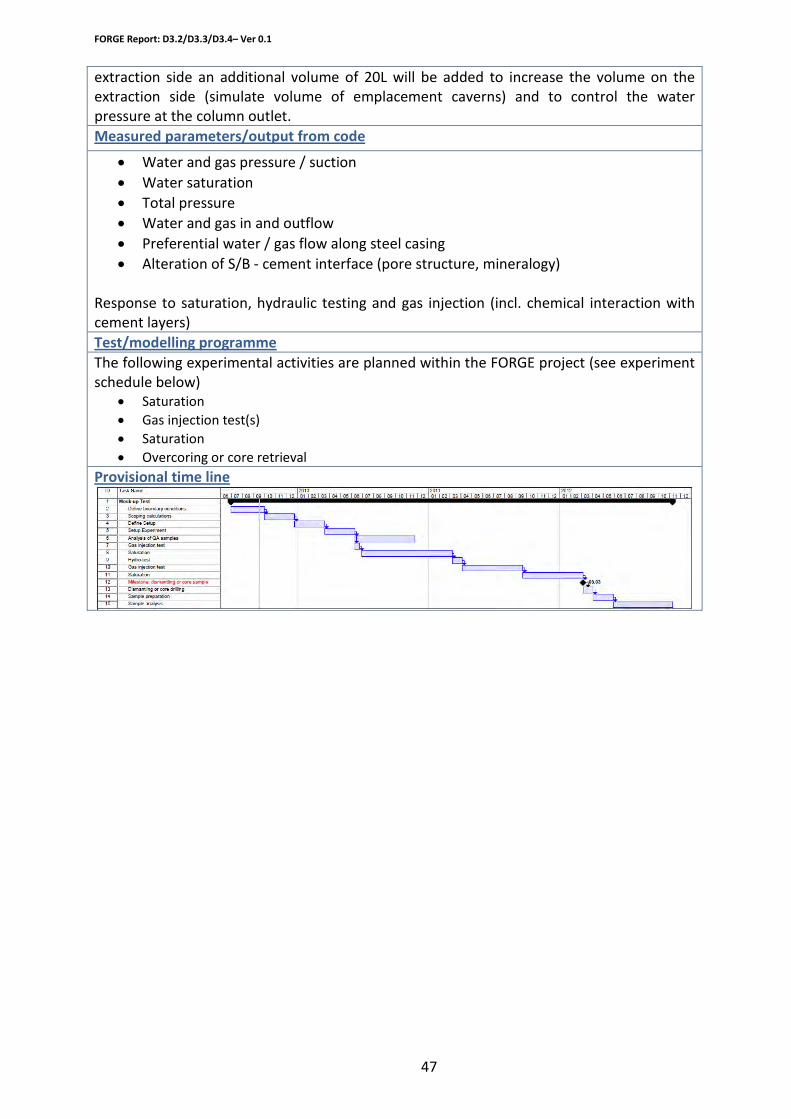
extraction side an additional volume of 20L will be added to increase the volume on the extraction side (simulate volume of emplacement caverns) and to control the water pressure at the column outlet.
• Water and gas pressure / suction
Measured parameters/output from code
• Water saturation • Total pressure • Water and gas in and outflow • Preferential water / gas flow along steel casing • Alteration of S/B - cement interface (pore structure, mineralogy)
Response to saturation, hydraulic testing and gas injection (incl. chemical interaction with cement layers)
The following experimental activities are planned within the FORGE project (see experiment schedule below)
Test/modelling programme
• Saturation • Gas injection test(s) • Saturation • Overcoring or core retrieval
Provisional time line
FORGE Report: D3.2/D3.3/D3.4– Ver 0.1
48
Experimental Systems and Planned Activities
Organisation
British Geological Survey
Work package
WP 3.4.1 Carbonation reactions of buffer/backfill cements and their impact upon gas and radionuclide migration
Description of planned research/modelling work
Some repository concepts envisage the use of large quantities of cementitious materials – both for repository construction and as a buffer/backfill. Key aspects of these materials are their good mechanical properties, and their ability to buffer pH to alkaline conditions. Such high pH conditions are important as they greatly limit metallic corrosion and radionuclide solubility - and as a consequence, radionuclide migration. Some wastes placed within a subsurface repository will contain a significant amount of organic material (e.g. ion-exchange resins, contaminated clothing etc). Over time, these may degrade to produce carbon dioxide, which will rapidly react with cement buffer/backfill to produce carbonate minerals such as calcite. The conversion of cement minerals to carbonates will reduce the ability of the buffer/backfill to maintain highly alkaline conditions and as a consequence its ability to limit radionuclide migration. However, the reaction may also alter the physical properties of the buffer/backfill, possibly changing its permeability and strength. Although carbonation reactions might improve some properties, it is currently unclear whether the overall changes due to carbonation will be beneficial to long-term radionuclide immobilisation, or deleterious. The work proposed will investigate these processes through laboratory experiments conducted at a range of likely future in situ repository conditions, including those expected over glacial timescales, that might influence the form of the carbon dioxide (i.e. dissolved, gas, liquid or supercritical).
Background
FORGE Report: D3.2/D3.3/D3.4– Ver 0.1
49
To conduct laboratory experiments under a range of realistic in-situ repository conditions to ascertain the effects of CO2 reaction upon:
Specifics of BGS activities
- cement mineralogy - cement porosity - cement permeability.
Experimental set-up/code description
The cement composition used is that of the ‘Nirex reference backfill cement’. Several kgs of this were prepared, cast into cylindrical moulds, and cured at atmospheric pressure for 28 days at 40°C.
Cement
Small cores of the above cement were cut for use in the experiments (typically 50 mm long / 25 mm diameter for the batch experiments, and 50 mm long / 50 mm diameter for the flow experiments).
Two types of experiments are being conducted: Experiments
- Numerous batch experiments aimed at providing information on changing mineralogy and porosity upon reaction with free phase and dissolved gaseous, liquid and supercritical CO2.
- A few flow experiments with mainly free phase and dissolved supercritical CO2 aimed at providing information on changing permeability upon reaction
As of early 2010, only the batch experiments have been run. Batch experiment details:
- They consist of a 50 mm long by 25 mm diameter core of cement (approx 40 g) suspended vertically within a Teflon-lined pressure vessel.
- Into the vessel is also added a stirrer bar and either: 1) approximately 230 ml of a synthetic ‘young’ cement porewater (rich in Na-K-OH), 2) approximately 230 ml of a synthetic ‘evolved’ cement porewater (rich in Ca-OH), or 3) no porewater at all.
- Vessels pressurised with either CO2 (reactive cases) or N2 (non-reactive case) to discriminate between reactions due to CO2 and any experimental artefacts.
- Batch experiments are being run at: 1) 20°C and 80 bar pressure [liquid CO2 stable], 2) 40°C and 40 bar pressure [gaseous CO2 stable], 3) 40°C and 80 bar pressure [supercritical CO2 stable].
- Experiments are stirred for 2 minutes every 4 hours to ensure they are well mixed.
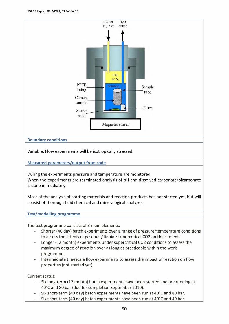
FORGE Report: D3.2/D3.3/D3.4– Ver 0.1
50
Boundary conditions
Variable. Flow experiments will be isotropically stressed.
Measured parameters/output from code
During the experiments pressure and temperature are monitored. When the experiments are terminated analysis of pH and dissolved carbonate/bicarbonate is done immediately. Most of the analysis of starting materials and reaction products has not started yet, but will consist of thorough fluid chemical and mineralogical analyses.
Test/modelling programme
The test programme consists of 3 main elements: - Shorter (40 day) batch experiments over a range of pressure/temperature conditions
to assess the effects of gaseous / liquid / supercritical CO2 on the cement. - Longer (12 month) experiments under supercritical CO2 conditions to assess the
maximum degree of reaction over as long as practicable within the work programme.
- Intermediate timescale flow experiments to assess the impact of reaction on flow properties (not started yet).
Current status:
- Six long-term (12 month) batch experiments have been started and are running at 40°C and 80 bar (due for completion September 2010).
- Six short-term (40 day) batch experiments have been run at 40°C and 80 bar. - Six short-term (40 day) batch experiments have been run at 40°C and 40 bar.

FORGE Report: D3.2/D3.3/D3.4– Ver 0.1
51
- Six short-term (40 day) batch experiments are currently running at 20°C and 80 bar (due for completion mid February 2010).
- Intermediate timescale flow experiments have not started yet, but purchase of equipment for these has started.
Provisional time line
February 2010: end of short-term batch experiments. February 2010 onwards: analysis of reaction products from short-term batch experiments. Spring 2010: setup of flow experiments. Late spring/early summer 2010 onwards: running flow experiments. September 2010: end of long-term batch experiments. September 2010 onwards: analysis of reaction products from long-term batch experiments.
FORGE Report: D3.2/D3.3/D3.4– Ver 0.1
52
Experimental Systems and Planned Activities
SCK-CEN Organisation
Work package
WP3.4 Gas migration in concrete* * the material that will be used is actually a cement based backfill (mortar)
Description of planned research/modelling work
A permeameter cell will be filled with a cement based backfill (mortar) and by applying a gas pressure we will examine how gas flows through concrete. This should provide us information concerning desaturation as a function of gas pressure, homogeneity of desaturation, gas permeability of the concrete and the transport of radionuclides by the gas flow.
A concrete sample will be sealed in an X-ray transparent permeameter cell by embedding it in a resin. First, the permeability will be tested because this value should give us a rough idea about the breakthrough pressure.
Experimental set-up/code description
Before the gas pressure is applied, the sample is scanned (µ-CT) to have a reference image. During the test, the pressure will be increased in different steps and the gasflow at the outlet is measured with a rotameter. CT scans are made at different pressure stages to visualise desaturation. After gas breakthrough the sample is scanned directly, and the breakthrough pressure is applied again for a while, followed by another scan. In the last phase, the pressure is once more increased, followed by a last CT scan. For the tests examining the RN transport, a small chamber is foreseen in the permeameter cell and this chamber is filled with a tracer solution. A gas pressure is applied and increased in different stages until gasbreakthrough is reached.
Boundary conditions
Parameters of the sample: Diameter: 86mm Height: 50 mm (preliminary dimensions!)
FORGE Report: D3.2/D3.3/D3.4– Ver 0.1
53
General parameters for the cement based backfill: Samples will be taken from the "small ESDRED mockup" which was an experiment to investigate the feasibility of injecting a mortar (as backfill) in a disposal gallery. Composition of the mortar:
• Binding medium (40 wt.%) o ¼ CEM I 52.5 N HSR LA o ¾ Limestone powder (CaCO3), from Carmeuse
• Additive (< 0.3 wt.% of the binding medium) o Superplasticizer Glenium® (polycarboxylate ether based material)
• Sand (≤ 60 wt.%) o Calibrated river sand 0 - 4 mm, washed and dried
The available parameters for this type of concrete are limited!
• Gas entry pressure: 0.7-0.8 MPa
Measured parameters/output from code
Outflow at differente pressure stages Desaturation in function of gas pressure (by µ-CT imaging). Gas permeabilty
Test/modelling programme
1. Sampling of the concrete 2. Measuring the saturation of the samples 3. Bringing all the samples at the same saturation level 4. Embedding the samples in resin and installation in the permeameter cells 5. Equilibration of the cells to restore the saturation level 6. Measuring permeability (100% saturation) 7. First µ-CT scan (100% saturation) 8. Application of gas pressure in different steps until breakthrough (+ µ-ct scan?) 9. Measuring flowrate at the outlet during gas breakthrough 10. Scan (desaturation at breakthrough pressure) 11. Keep sample under pressure (breakthrough pressure) 12. Scan (progressing desaturation as function of time) 13. Increase pressure 14. Scan (progressing desaturation as function of time and increased pressure) 15. Tracer tests
Provisional time line
March – december 2010: • Sampling • Saturation at constant humidity • Development of the permeameter cells

FORGE Report: D3.2/D3.3/D3.4– Ver 0.1
54
• D3.14: Detailed description on gas migration test in concrete (M24) 2011
• Measuring permeability • Preliminary tests
2012
• Gas breakthrough tests • Tracer tests • D3.26 Results and interpretation of the gas migration tests (concrete) M42

FORGE Report: D3.2/D3.3/D3.4– Ver 0.1
55
3. Description of proposed initial numerical codes and conceptual models
The current section describes the conceptual models and the numerical approaches for the modelling activities in WP3.

FORGE Report: D3.2/D3.3/D3.4– Ver 0.1
55
3. Description of proposed initial numerical codes and conceptual models
The current section describes the conceptual models and the numerical approaches for the modelling activities in WP3.
FORGE Report: D3.2/D3.3/D3.4– Ver 0.1
56
Experimental Systems and Planned Activities
Organisation
CIMNE - UPC
Work package
WP3
Description of planned research/modelling work
LASGIT IN SITU TEST MODELLING
Review of available data for Lasgit in situ test and development of a numerical model. The objective is to understand the way the in situ experiment is performed. This is very important for the development of the geometry of the model, the materials that are considered and the boundary conditions applied.
Experimental set-up/code description
1.1.1.1 CODE_BRIGHT (WP3)
1. General features of computer codes for WP3
Name of code: CODE_BRIGHT
Method used: FEM
Dimensionality; 1D, 2D & 3D
Processes: Coupled THM
Previous application cases: CATSIUS CLAY, BAMBUS I and II, FEBEX I and II, RESEAL I and II, HE-B, EBS, NF-PRO, Prototype, TBT, DECOVALEX-III
FORGE Report: D3.2/D3.3/D3.4– Ver 0.1
57
2. Some features important to WP3
The code has options that allow the solution of uncoupled or coupled problems, for instance, M, H, T, HM, TM, TH, and THM. The types of analyses can be 1D (uni-axial confined strain and axisymmetric), 2D (plane strain and axisymmetric) and fully 3D. The constitutive laws are defined by a set of parameters with alternative types of relations for different application cases.
The types of boundary conditions are:
- Mechanical problem: forces and displacement rate in any spatial direction.
- Hydraulic problem: mass flow rate of water and air prescribed and liquid/gas pressure prescribed.
- Thermal problem: heat flow rate prescribed and temperature prescribed.
However, the thermal problem will not be considered in the analysis to be performed within WP3.
The convergence criteria are defined by tolerances for absolute and relative error independent for each unknown, and tolerance for residual convergence of each problem (mechanical, hydraulic, etc.).
The output options include spatial distribution of variables at user defined time points, and time evolution of variables at user defined space points
3. Mathematical representation of mechanical processes
3.1 Equations of motion
The equation of equilibrium of stresses, the mass balance (water and air) and the energy balance are:
Where:
∇ ⋅ + =σ b 0
( ) ( ) w w w w wl l l g g g l gS S f
t∂
ω ρ φ+ω ρ φ +∇⋅ + =∂
j j
( ) ( ) a a a a al l l g g g l gS S f
t∂
ω ρ φ+ω ρ φ +∇⋅ + =∂
j j
( )( )1 ( ) Qs s l l l g g g c Es El EgE E S E S f
t∂ ρ φ ρ φ ρ φ∂
− + + +∇⋅ + + + =i j j j
(1)
FORGE Report: D3.2/D3.3/D3.4– Ver 0.1
58
(Note: Bold non italic symbols mean vector or tensor)
3.2 Mechanical constitutive model
The viscoplasticity is assumed for bentonite in WP3 as unsaturated soils based on Basic Barcelona Model, and linear elasticity behaviour is assumed for other materials.
The strain terms are defined as:
where is the elastic strain tensor (with stress, temperature and suction terms), D the
elasticity tensor, the viscoplastic strain rate tensor, Γ is the viscoplastic parameter,
the plastic flow function, F is the yield surface, and G is the plastic potential function.
F0 is a reference stress to normalise F, N is a parameter of the model,
and the Makulay brackets are used.
The model uses the effective stress and suction as state variables. Effectives stress is defines
as: .
The thermal expansion of materials is considered. The parameters of the constitutive laws change with temperature and suction. The elastic terms in equation (2) related to temperature and suction are obtained from the following equation for volumetric
deformations: where as MPa-1 is swelling coefficient for
φ: porosity b: body forces, ρ: density ω: mass fraction, j: total mass flux ωρ: mass content per unit volume of
phase, i: non-advective mass flux E: specific internal energy q: advective flux ic: conductive heat flux u: solid displacements jE: energy fluxes due to mass motion σ: stress tensor Sl, Sg: degree of saturation of liquid and gas phases i.e., fraction of
pore volume occupied by each phase. Superscripts w and a refer to water and air, respectively Subscripts s, l and g refer to solid, liquid and gas phase, respectively.
eε vpε
( )Fϕ ( ) ( )0
NF F F=φ
( )' max ,g lP Pσ σ= −
( )3 3V s s g lb T a P P∆ε = ∆ + ∆ −
FORGE Report: D3.2/D3.3/D3.4– Ver 0.1
59
changes in suction and bs oC-1 is a Linear thermal expansion coefficient for the medium
Integration of (2) gives the stress increments as a function of the strain increments, temperature increments and suction increments.
The triaxial yield surface and plastic potential functions to be used in (2) are given by:
where is the net average stress, is the deviatoric stress, is the matrix suction, M is the slope of critical state shear strength, α is the parameter that defines the non-associative
of plastic potential (with α = 1.0 indicating an associate flow rule), , and
the material parameter that controls the increase in cohesion with suction, respectively. Parameter P0 represents the loading-collapse curve (LC), is given by
where is the reference stress of the loading-collapse curve, is the initial yield mean net stress, and is the virgin compressibility for saturated condition, with being the slope of the virgin elastic compressibility for saturated condition and the slope of the unload-reload line. The parameter λ(s) is the volumetric compressibility index, written as
where r is the parameter that establishes the minimum value of the compressibility index for high values of suction, and [?] is the parameter that controls the rate of increase in stiffness with suction.
The hardening law is given as
where is the void ratio, and is the plastic volumetric strain increment.
4. Mathematical representation of fluid flow processes.
( ) ( )[ ] ( )[ ] 0,, 22 =−+−= pspsppMqsqpF os (4)
( ) ( )[ ] ( )[ ] 0,, 22 =−+−= pspsppMqsqpG osα (5)
p q s
sksp ss =)( sk
( ) κλκλ
−−
=
)()0(
* s
coco
pppsp (6)
cp *op κλ −)0( )0(λ
κ
( ) ( ) ( ) ( )[ ]rsrs +−−= βλλ exp10 (7)
( )( )
pv
oo dpedp ε
κλ −+
=0
1 ** (8)
e pvdε
FORGE Report: D3.2/D3.3/D3.4– Ver 0.1
60
The fluid flow are governed by mass balance equations
with the flux terms defined as (sum of nonadvective and advective terms).
and Darcy’s law
Intrinsic permeability of the matrix material is dependent on porosity through Kozeny’s law:
is the flow rate in the porous media, is the intrinsic permeability for matrix at porosity
, is the intrinsic permeability for matrix at porosity , is the phase relative
permeability of phase α, µα is the viscosity of the fluid phase α, the pressure of the fluid phase α, the density of the fluid phase α and g the vector of gravity acceleration,
respectively. Parameters and are defined as before.
The fluid density changes with temperature and with pressure. For the gas phase, the ideal gases law is used.
Relative permeability is considered with the van Genuchten function or a power of degree of
saturation: . A coupling of flow and deformations is
achieved by Kozeny’s equation. However, primary couplings appear from balance equations.
Advection of water and air in gas and liquid phases is calculated by means Darcy’s law. Non
( ) ( ) ,i i i i il l l g g g l gS S f i a w
t+ +∇⋅ + = =j j∂ ω ρ φ ω ρ φ
∂
, ; ,
i i i i dSdt
i a w l g
α α α α α α α αω ρ ω ρ φ
α
= + +
= =
uj i q
( )gkq ααα
αα ρ
µ−∇−= Pkr
3
2
2
3 )1()1( o
oo
φφ
φφ −−
= kk
αq k
φ ok oφ αrk αP
αρ oφ φ
( )( ) ( )2
1/1 1 ; nr l l r lk S S k S= − − =
λλα α
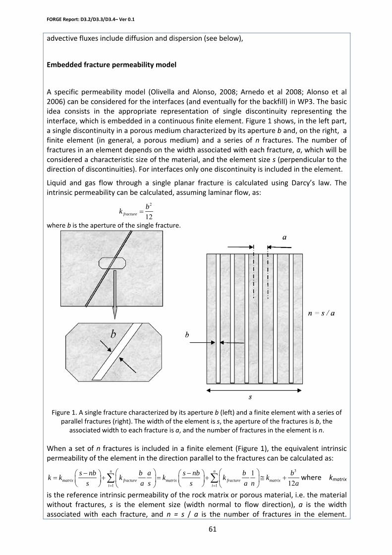
FORGE Report: D3.2/D3.3/D3.4– Ver 0.1
61
advective fluxes include diffusion and dispersion (see below),
Embedded fracture permeability model
A specific permeability model (Olivella and Alonso, 2008; Arnedo et al 2008; Alonso et al 2006) can be considered for the interfaces (and eventually for the backfill) in WP3. The basic idea consists in the appropriate representation of single discontinuity representing the interface, which is embedded in a continuous finite element. Figure 1 shows, in the left part, a single discontinuity in a porous medium characterized by its aperture b and, on the right, a finite element (in general, a porous medium) and a series of n fractures. The number of fractures in an element depends on the width associated with each fracture, a, which will be considered a characteristic size of the material, and the element size s (perpendicular to the direction of discontinuities). For interfaces only one discontinuity is included in the element.
Liquid and gas flow through a single planar fracture is calculated using Darcy’s law. The intrinsic permeability can be calculated, assuming laminar flow, as:
where b is the aperture of the single fracture.
Figure 1. A single fracture characterized by its aperture b (left) and a finite element with a series of
parallel fractures (right). The width of the element is s, the aperture of the fractures is b, the associated width to each fracture is a, and the number of fractures in the element is n.
When a set of n fractures is included in a finite element (Figure 1), the equivalent intrinsic permeability of the element in the direction parallel to the fractures can be calculated as:
where kmatrix
is the reference intrinsic permeability of the rock matrix or porous material, i.e. the material without fractures, s is the element size (width normal to flow direction), a is the width associated with each fracture, and n = s / a is the number of fractures in the element.
2
12=fracture
bk
3
1 1
112
n n
matrix fracture matrix fracture matrixi i
s nb b a s nb b bk k k k k ks a s s a n a= =
− − = + = + ≅ +
∑ ∑

FORGE Report: D3.2/D3.3/D3.4– Ver 0.1
62
Permeability of the matrix will be relevant only for very low apertures; otherwise fracture permeability will dominate the total permeability and matrix permeability will be negligible in comparative terms.
The variation of capillary pressure induced by aperture changes is also included. According to Kelvin’s law the capillary pressure necessary to desaturate a fracture is given by:
which is obtained when (1/r1) = 0 and r2 = b/2 (the wetting angle has been assumed to be 0). This equation can be used directly to calculate the air entry value of the element. If equation (4) is combined with equation (3) the capillary pressure to start desaturation is obtained as:
Where Po is the capillary pressure for a reference permeability ko, which eventually can be the initial permeability. As a first approximation the capillary pressure associated with the discontinuity can be introduced in the standard water retention curve of Van Genuchten (Van Genuchten, 1980).
The aperture of the fracture can be estimated as a function of deformation in the following way:
It has been assumed that deformation is localized and results in changes in aperture. A threshold value (εo) is considered. Therefore the changes in aperture start when deformation reaches this value. Deformation perpendicular to the fracture plane is to be used when aperture changes have to be obtained. The threshold value (εo) is associated with fracture initiation. This parameter will be set to zero if the fractures already exist and have an initial aperture bo. The initial aperture can be also zero when the fractures exist but are closed.
Retention curve
The hydraulic conductivity of the materials considered depends on their degree of saturation. The retention curve (Van Genuchten Model) is
where Se is the degree of saturation of porous media, Sl is the degree of saturation of liquid, Srl is the residual degree of saturation, Sls is the maximum degree of saturation, Pg is the gas
1 2
1 1 2 = + =
oP
r r bσσ
3
3
oo
kP P
k=
for 0( ) ( / )( ) for
o
o o o
b b b bb a a s n= + ∆ ∆ ≥
∆ = ∆ = − = − >ε ε ε ε ε ε ε
λλ −−
−
+=−−
=)1/(1
1P
PPSSSSS lg
rlls
rlle
ooPPσσ
=

FORGE Report: D3.2/D3.3/D3.4– Ver 0.1
63
pressure, Pl is the liquid pressure, [?] is the shape function coefficient for the retention curve, Po is the pressure of air entrance at a reference temperature, and [?] is the surface tension at a temperature at which Po was measured. [?] is the surface tension at a temperature T. (Pruess, 1987).
Molecular Diffusion.
The molecular diffusion is governed by Fick’s law
where is the non-advective mass flux vector(i), the porosity of porous media, is the
density of the phase , is the degree of saturation of the phase , is the diffusion
coefficient (i), and is the mass fraction(i). The superindex refers to species, and the
subindex refers to phases. I is the identity tensor.
The diffusion coefficient of dissolved air is given by
where the molar heat capacity and is the ideal gas constant, D = 1.1×10⁻⁴ m2/s and Q =24530 J/mol.
Mechanical Dispersion.
The mechanical dispersion is governed by Fick’s law, given by
where is the non-advective mass flux, with superindex refers to species and the
subindex is refers to phase, is the density of the phase , is the mechanical
dispersion (which is described as a function of dispersivities) tensor and is the mass
( ) iii DS ααααα ωφρ ∇−= Ii
iαi φ
αρ
α αS α iDα
iαω i
α
+
−=
)15.273(exp
TRQDD soluteorair τα
Q R
( )''i i= − ∇i D Iα α α αρ ω
'iαi i
α αρ α '
αD i
αω
FORGE Report: D3.2/D3.3/D3.4– Ver 0.1
64
fraction, respectively.
Boundary conditions
The development of the 3-D geometry concentrates on the backfill material and surrounding elements (excludes the host rock). Calculation of hydration phase under hydro-mechanical conditions starting from an initial condition of pressures and saturations is the first step. Determination of times required for full saturation depending on the initial conditions and hydraulic properties. After that the initial conditions (initial suctions) are reviewed and also the boundary conditions (gas and water sinks representing several rock fractures that intersect the deposition hole wall).
Measured parameters/output from code
The final objective is the comparison of several calculated variables (such as gas and liquid pressures, displacements) with measurements. This may imply reconsideration of assumptions performed during model development and material parameters modifications.
Test/modelling programme
The modelling programme consists in the following phases:
-Development of three dimensional model under simplified conditions, including possible interfases
-Adoption of parameters based on literature review or new experimental work
-Simulation of two phase flow (water hydration plus gas injection)
-Simulation of two phase flow coupled to mechanical problem
-Parameter calibration using measured results from the in situ test
Provisional time line
The three dimensional model and the two phase flow calculations will be carried out during the first year of the project.
FORGE Report: D3.2/D3.3/D3.4– Ver 0.1
65
Experimental Systems and Planned Activities
Organisation
SKB (Clay Technology)
WP 3.2
Work package
Model development of gas migration in saturated bentonite
Description of planned research/modelling work
Two gas migration tests (performed at the British Geological Survey, /Harrington and Horseman, 2003/) have been modelled by Clay Technology within the EBS Task Force project. Included in this work has been the development of a conceptual view of gas migration processes based on thermodynamics /Birgersson et al., 2008/. This view adopts a homogeneous, isotropic model of a confined clay system and gas intrusion is accomplished by consolidation of the clay. The criterion for gas entry is shown to be
Experimental set-up/code description
liquidsgas PPP −>
where gasP denotes gas pressure, liquidP quantifies the chemical potential of water and sP is
swelling pressure in a system with access to non-pressurized water.
The modeling was performed both by analytical work and by numerical simulations using the finite element (FEM) based code Code_Bright. This is a fully coupled code for simulation of thermal, hydraulic (gas and liquid) and mechanical properties in porous media. The code was adapted to the present conceptual clay model by suitable choices of input parameters such as water retention curves and hydraulic transport parameters. Although the detailed gas phase propagation was not considered in this work, quantitative agreement between model and experiments was achieved both for gas pressure evolution and gas outflow.
The model applies to volume restricted water saturated bentonite
Boundary conditions
Primarily, the modelling will provide conceptual insight to the gas migration process in
Measured parameters/output from code

FORGE Report: D3.2/D3.3/D3.4– Ver 0.1
66
bentonite.
The calculated quantities are the same as will be measured in lab tests: Total pressure, Gas pressure, Water flux and gas flux
The current model and concepts will be developed. Specific topics include:
Test/modelling programme
• Details of gas propagation. Could this be related to water retention properties at the atomic level in a convenient manner? How does it couple to the parallel process of transporting water out of the system during consolidation?
• A continued review and possible modification of Code_Bright. • Development of a model using ABAQUS, an alternative numerical FEM-code. This
would be rewarding both as a comparison to Code_Bright and because ABAQUS has a set of different features (e.g. contact elements).
• Scaling effects. How important is the effect of compression (without water transport) for systems at the meter rather than centimeter scale?
• The effect of impure materials. The present model is valid for materials dominated by montmorillonite (>70%). At what montmorillonite content must the role of accessory minerals explicitly be taken into account? How does the behavior change?
• Counter ion configuration. The mechanical properties of bentonite are rather different depending on what type of counter ion is dominating the system (e.g. Na+ or Ca2+). Therefore a different gas migration behavior could also be expected.
• Application of the model to more migration experiments, both at laboratory and field scale (Lasgit).
The work will be ongoing 2010 - 2012
Provisional time line
FORGE Report: D3.2/D3.3/D3.4– Ver 0.1
67
References Barton, C., A., Zoback, M. D. & Moos, D. (1995). Fluid flow along potentially active faults in crystalline rock. Geology, 23, 683–686.
Buzzi, O., Boulon, M., Deleruyelle, F. & Besnus F. (2006). Hydromechanical Behaviour of Rock-Bentonite Interfaces Under Compression. Rock Mech. Rock Engng. 41 (2), 343–371.
Sitz, P. (2003). Entwicklung eines Grundkonzeptes für langzeitstabile Streckenverschlussbauwerke für UTD im Salinar, Bau und Test eines Versuchsverschlussbauwerkes unter realen Bedingungen (BMBF-gefördertes F/E-Vorhaben Nr. 02 C 05472). Abschlußbericht, TU Bergakademie Freiberg, Institut für Bergbau, 2003.
Alonso, E.E., A. Gens and A. Josa (1990). A constitutive model for partially saturated soils. Géotechnique, 40(3), 405-430.
Arnedo, D., E. E. Alonso, S. Olivella & E. Romero (2008). Gas injection tests on sand/bentonite mixtures in the laboratory. Experimental results and numerical modelling. Physics and Chemistry of the Earth, 33 Suplement, 237- 247, doi:10.1016/j.pce.20.
Alonso, E.E., S. Olivella and D. Arnedo, Mechanisms of gas transport in clay barriers. 2007 J. Iberian Geol. 32, No. 2, 175–196.
Olivella S., Gens A., Carrera J. and Alonso E.E. (1996). Numerical formulation for a simulator (CODE_BRIGHT) for the coupled analysis of saline media. Engineering Computations. 13(7): 87-112.
Olivella, S., J. Carrera, A. Gens & E.E. Alonso (1994) Nonisothermal multiphase flow of brine and gas through saline media. Transport in Porous Media, 15: 271-293.
Olivella, S. & Alonso, E.E. 2008. Gas flow through clay barriers. Géotechnique: 58 (3), 157–176.
Van Genuchten, M. Th. 1980. Closed-form equation for predicting the hydraulic conductivity of unsaturated soils, Soil Sci. Soc. Am. J.: 44, 892-898.
Birgersson M., Åkesson M. and Hökmark H., 2008, Gas intrusion in saturated bentonite – A thermodynamic approach. Phys. Chem. Earth., 33, S248 – S251
Harrington, J.F. and Horseman S.T., 2003, Gas migration in KBS-3 buffer bentonite. Sensitivity of test parameters to experimental boundary conditions, SKB Technical Report, TR-03-02, SKB, Stockholm