depth of field simulation for still digital images using a...
TRANSCRIPT

COMPUTER SCIENCE & IT
ReCIBE, Year 3 No.3, November 2014
Depth of field simulation for still digital images
using a 3D camera
Omar Alejandro Rodríguez Rosas
Asistente de Investigación en Universidad de Guadalajara
Guadalajara, México
Abstract: In a world where digital photography is almost ubiquitous, the size of
image capturing devices and their lenses limit their capabilities to achieve
shallower depths of field for aesthetic purposes. This work proposes a novel
approach to simulate this effect using the color and depth images from a 3D
camera. Comparative tests yielded results similar to those of a regular lens.
Keywords: bokeh; depth of field; simulation.
Profundidad de simulación de campo para imágenes fijas
digitales utilizando una cámara 3D
Resumen: En un mundo donde la fotografía digital es casi omnipresente, el
tamaño de los dispositivos de captura de imagen y sus lentes limitan sus
capacidades para alcanzar profundidades menores de campo para fines
estéticos. Este trabajo propone un enfoque novedoso para simular este efecto
usando el color e imágenes profundas de una cámara 3D. Las pruebas
comparativas dieron resultados similares a los de una lente regular.
Palabras clave: bokeh; profundidad de campo; simulación.

1. Introduction
Since the release of the first commercial camera in the early 1990s, digital
photography has stopped being perceived as a luxury reserved for the
wealthiest and progressively became inherent to our daily lives. The new
semiconductor technologies and manufacturing techniques allow vendors to
attach digital cameras to a huge variety of appliances from mobile phones and
tablets to medical equipment and wearable devices by progressively reducing
their cost and physical dimensions.
Nevertheless, these reductions have compromised to some extent the quality of
the captured images: by allowing them to adjust to the increasingly tighter size
constraints of the market, some features from high-end cameras like flexible
depths of field and the lens bokeh need to be sacrificed.
Depth of field, in optics, is defined as the distance at which objects in front or
behind the focal plane appear acceptably sharp. Other points in the scene
outside this area render themselves as blurry spots shaped as the camera’s
diaphragm whose diameter contract gradually as its distance approaches the
focal plane (see figure 1). The maximum diameter of one of these spots that is
indistinguishable from a focused point is called maximum permissible circle of
confusion or simply circle of confusion. The appearance of these unfocused
areas, that is, how pleasant or unpleasant they are, will depend on a number of
factors including size, shape and number of blades of the camera’s diaphragm
and optical aberrations of the lens. The Japanese term bokeh is often employed
as a subjective measure to describe the aesthetic quality of the out-of-focus
areas in the final picture (Buhler & Dan, 2002).

Figure 1. Schematic view of the Circle of Confusion physics.
2. Depth of field in modern small devices
A shallower depth of field (which means a bigger circle of confusion) is often a
desired behavior since it provides emphasis to certain subjects in a picture, but
implies the use of bigger aperture values and focal lengths. Given these
requirements, it´s not hard to understand why the effect is often disregarded in
portable devices such as tablets and cellphones (Z, 2014) where physical size
and final price constraints for the finished product and its components are an
important design factor.
3. Current solutions
Depth of field simulation is not a new technique and it is, in fact, quite common
in areas such as 3D rendering where a distance dependent blur is achieved
through Gaussian filtering or post processing methods as circle of confusion
physics simulation (Rigger, Tatarchuk, & Isidoro, 2003). Other real-time
optimized techniques in the graphics industry suggest to render two separate

versions of each frame: one without any visible Depth of Field and a blurred
representation of the same image. The data from the z-buffer, which contains
depth information for each pixel, is then interpreted as an alpha channel to
blend the two separate frames reducing the sharpness and color saturation in
the out-of-focus portions of the scene (U.S. Patent No. 7081892, 2002).
Although realistic, efficient and well suited for 3D rendering, due to the lack of
depth data, these techniques are not an option for standard digital photography.
The problem is then reduced to the acquisition of each point’s 3D position.
One way to obtain depth information from digital photographs is the use of light
field cameras. This kind of device utilize an array of microscopic lenses placed
between the main lens and the photo sensor to sample information about the
light field of the image, containing the direction of the light rays passing through
each point, which is typically employed to reconstruct the picture using ray-
tracing techniques to simulate its imaging plane (Ng, 2006). Nevertheless, this
technology is not yet widely adopted, nor available for portable devices.
To address both depth data acquisition from 2D digital images and the
representation of distance dependent blurring, the Google Camera App for
Android 4.4 provides the “Lens blur” mode which enables users to take pictures
using simulated shallow depths of field, similar to those of SLR cameras. This
application relies on the approximation of a 3D map of the scene based on a
series of consecutive photographs. The initial images are obtained from a
continuous stream whose capture is controlled by the user as an upward
sweep. The resulting pictures will then represent the scene from different
elevation angles. Using Structure-from-Motion (SfM), Bundle Adjustment and
Multi-View Stereo (MVS) algorithms, the estimated 3D positions of each point in
the image can be triangulated and the resulting map employed to render the
appropriate amount of blur for each pixel according to its depth using a Thin
Lens approximation (Hernández, 2014). This method, along with similar
technologies from vendors as HTC or Samsung, are indeed precise but require
a time-consuming preprocessing in order to construct the 3D map.
As an alternative, some relatively inexpensive 3D cameras like Microsoft Kinect
or Creative Senz3d can provide a three-dimensional map of the scene at up to
30 frames per second, but since they are primarily targeted for PC’s, up until
recently, developments for portable devices based on these technologies were
not a realistic option. Fortunately, after the announcements by some vendors
regarding the inclusion of similar technologies in tablets and laptops in the near
future (Tibken, 2013), and the launching of Occipital’s Structure sensor (a depth
sensor for iPad) earlier this year, the possibility of practical solutions utilizing
this kind of device sounds more and more feasible.
Considering that, the following sections propose a theoretical methodology to
achieve depth of field simulation and an implementation on currently available
hardware that should be easily portable to other mobile technologies as soon
as they are available.
4. Solution proposal
This proposal for depth of field simulation uses both the color and depth feeds
from a 3D camera. As portrayed in figure 2, a summary of the required steps is:
1. Read depth and color frames from the camera.
2. Create a copy of the color frame
3. Apply a blur function to the color frame copy.
4. If necessary, apply a rectification function to map depth pixels to color space.
5. Use a pixel-weight function to translate depth data into alpha channel values.
6. Blend the two color frames (the original and the blurred one) using the previously calculated alpha values.

Figure 2. The Depth of field simulation process.
Some of these steps are further explained next.
4.1. Blur function
During this stage, blurring will be applied the entire duplicated color frame. The
intensity of the effect should be the expected for the farthest points from the
focal plane. In the absence of a physical lens to render its optical aberrations to
the sensor, the quality of the bokeh will be determined by this step of the
process, hence the importance of the method selection. To take an appropriate
decision, it is useful to consider that while standard point sampling techniques
have uniform density distributions, real lenses tend to display a distinct behavior
at different planes, which can be achieved by implementing arbitrary probability
density functions to jitter the sampling points amongst those planes (Buhler &
Dan, 2002). The final selection will depend on the particular implementation
requirements such as performance, available hardware, accuracy and other
considerations regarding the quality and computational cost trade-off. Good
candidates for this function are Separable Gaussian Blur, Circle of confusion
simulation (Rigger, Tatarchuk, & Isidoro, 2003), Optical Aberration-based
models (Wu, Zheng, Hu, Wang, & Zhang, 2010), Box blur and FFT-based
models.
4.2. Rectification function
Since 3D cameras generally use two lenses at slightly different resolutions and
distances from each other, a noticeable offset between the color and depth
frames may exist. To achieve realistic results, it is necessary to map each depth
pixel information to its corresponding color space representation.
This operation can be performed by standard Epipolar-geometry-based
rectification methods (such as those designed for stereoscopic cameras
calibration) which, although out of the scope of this article, are implemented in
several API´s for computer vision including OpenCV and the Microsoft Kinect
SDK.
4.3. Pixel-weight function
Using this function we translate depth values from the 3D camera’s sensor to
transparency alpha values which will be applied to blend the blurred version of
the color image in order to make objects whose circles of confusion are
supposed to be smaller fully transparent and vice versa. For biconvex lenses
(commonly used for photography) the relationship between the diameter of the
circle of confusion and the distance from the subject to the focal length is
described by equation 1:
Cd = A (|d-df|)/d (1)
Where Cd is the diameter of the circle of confusion, A the aperture value, d the
distance of a given object from the lens and df the distance from the lens to the
focal plane (see figure 1). The circle of confusion diameter as a function of the
distance from a subject for a given aperture value and focal plane is depicted in
figure 3.
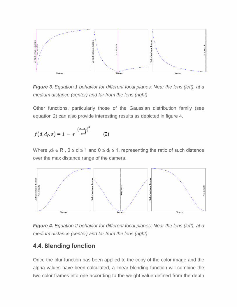
Figure 3. Equation 1 behavior for different focal planes: Near the lens (left), at a
medium distance (center) and far from the lens (right)
Other functions, particularly those of the Gaussian distribution family (see
equation 2) can also provide interesting results as depicted in figure 4.
Where ,df ∈ R , 0 ≤ d ≤ 1 and 0 ≤ df ≤ 1, representing the ratio of such distance
over the max distance range of the camera.
Figure 4. Equation 2 behavior for different focal planes: Near the lens (left), at a
medium distance (center) and far from the lens (right)
4.4. Blending function
Once the blur function has been applied to the copy of the color image and the
alpha values have been calculated, a linear blending function will combine the
two color frames into one according to the weight value defined from the depth
data. To do so, for each pixel, the final color value is calculated using equation
3:
O'RGB = BRGBα + ORGB (1- α) (3)
which is a simplification of the general linear blending equation assuming a
totally opaque background where O'RGB is a pixel from the blended output color
image, BRGB is the blurred version of the original color image, α is an alpha
value such that 0≤ α ≤1 and ORGB is a pixel from the original color frame.
5. Implementation
For this paper, an implementation using Microsoft´s Kinect for Windows and its
SDK has been coded. The color and depth information are retrieved from its
color (RGB) and depth (infrared) cameras respectively
For the blur function, a separable Gaussian blur has been implemented. Given
that a considerable amount of blur is needed, the convolution kernel has to be
big. For a discrete kernel of a 2σ radius (where σ is the standard deviation of
the Gaussian kernel), the loss of precision on peripheral values, may cause a
diminution of luminosity. This effect is compensated dividing each element of
the kernel by an empirically obtained constant (1.8 for this implementation).
For frame rectification, Microsoft’s Kinect SDK 1.8 provides the
MapDepthFrameToColorFrame() method which, as the name suggests, allows
us to map depth pixels to their corresponding locations in color space.
The application’s graphic interface displays a real time preview of the color
camera view, a slider that allows the user to select the focal plane distance and
a text box to select the σ parameter for the Gaussian Blur kernel generation,
that is, the blur radius (directly proportional to its intensity).
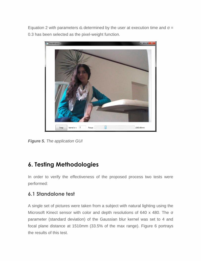
Equation 2 with parameters df determined by the user at execution time and σ =
0.3 has been selected as the pixel-weight function.
Figure 5. The application GUI
6. Testing Methodologies
In order to verify the effectiveness of the proposed process two tests were
performed:
6.1 Standalone test
A single set of pictures were taken from a subject with natural lighting using the
Microsoft Kinect sensor with color and depth resolutions of 640 x 480. The σ
parameter (standard deviation) of the Gaussian blur kernel was set to 4 and
focal plane distance at 1510mm (33.5% of the max range). Figure 6 portrays
the results of this test.

Figure 6. Results from the standalone test: a) Final image. b) Detail from the
original image. c) Detail from the blurred copy. d) Detail from the final image.
6.2. Benchmark test
To perform a qualitative analysis of the final images rendered with this
technique, its results were compared to similar shots obtained with a regular
consumer digital camera. Reference pictures were taken with a Canon REBEL
EOS T5i camera with an aperture of f/4 at 1/80s and a color temperature of
approximately 4000K to achieve similar colors to those from the Kinect. Both
the reference camera and the Kinect where placed at the same distance from
the subject, that is, 1.40 m (see figure 7). For comparison purposes the Kinect
image was horizontally mirrored from its original orientation. Color and depth
resolutions were set to 640 x 480.
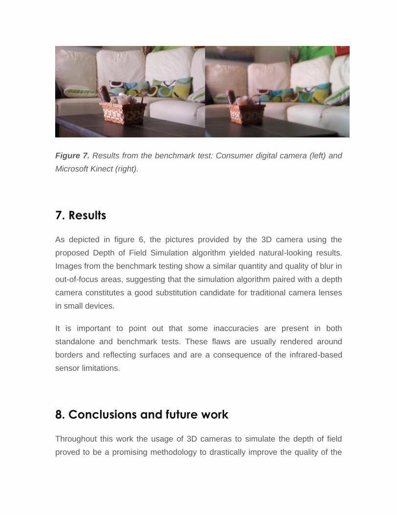
Figure 7. Results from the benchmark test: Consumer digital camera (left) and
Microsoft Kinect (right).
7. Results
As depicted in figure 6, the pictures provided by the 3D camera using the
proposed Depth of Field Simulation algorithm yielded natural-looking results.
Images from the benchmark testing show a similar quantity and quality of blur in
out-of-focus areas, suggesting that the simulation algorithm paired with a depth
camera constitutes a good substitution candidate for traditional camera lenses
in small devices.
It is important to point out that some inaccuracies are present in both
standalone and benchmark tests. These flaws are usually rendered around
borders and reflecting surfaces and are a consequence of the infrared-based
sensor limitations.
8. Conclusions and future work
Throughout this work the usage of 3D cameras to simulate the depth of field
proved to be a promising methodology to drastically improve the quality of the

pictures without the need for expensive, heavy and delicate additional optics.
This is particularly interesting if, as stated by some vendors, depth sensors
become cheaper, smaller and widely available in coming years.
This method differs from others currently on the market solely on the acquisition
time of the depth map which for Microsoft Kinect and Creative Senz3d can be
as fast as 30 fps seconds (around 0.0333 seconds) and up to 60 fps (.0166
seconds) for Occipital Structure sensor, a process that might take several
seconds for current implementations of optical-based methods such as the
Google Camera app.
This paper offers as well interesting areas of improvement, such as the use of
additional depth measurement techniques (like optical or acoustic sensors) to
increase the accuracy and quality of the images or the utilization of Graphics
hardware to speed up the processing of the highly parallelizable operations
taking place in the current implementation, making possible its usage for real-
time video capturing as well.
References
Alkouh, H. B. (2002). U.S. Patent No. 7081892.
Buhler, J., & Dan, W. (2002). A Phenomenological Model for Bokeh Rendering.
ACM SIGGRAPH 2002 conference abstracts and applications (p. 142). New
York, NY, USA: ACM.
Hernández, C. (2014, April 16). Lens Blur in the new Google Camera app.
Retrieved from Google reasearch blog:
http://googleresearch.blogspot.mx/2014/04/lens-blur-in-new-google-camera-
app.html
Ng, R. (2006). Digital light field photography. (Doctoral Dissertation). Stanford
University.
Rigger, G., Tatarchuk, N., & Isidoro, J. (2003). ShaderX2 – Shader Programming
Tips and Tricks with DirectX 9. Wordware.

Tibken, S. (2013, November 29). Wave fingers, make faces: The future of
computing at Intel. Retrieved from Cnet news:
http://www.cnet.com/news/wave-fingers-make-faces-the-future-of-
computing-at-intel/
Wu, J., Zheng, C., Hu, X., Wang, Y., & Zhang, L. (2010, June 1). Realistic
rendering of bokeh effect based on optical aberrations. The Visual Computer,
26(6-8), 555-563.
Z, E. (2014, April 14). tempo.co. Retrieved from
http://en.tempo.co/read/news/2014/04/18/240571603/Google-Releases-
Android-Camera-App
Biographical notes:
Omar Alejandro Rodríguez Rosas He obtained his Bachelor´s
degree in Computer Science Engineering from the University of
Guadalajara. He worked for two years at Intel as an Intern for the
Visual and Parallel-Computing Group. He is currently a member of the
multidisciplinary art collective Proyecto Caos and collaborates as a research
assistant for the Intelligent Systems laboratory at the University of
Guadalajara’s University Center for Exact Sciences and Engineering.
Esta obra está bajo una licencia de Creative Commons
Reconocimiento-NoComercial-CompartirIgual 2.5 México.