depot maintenance facility improvements. the bid opening ...2. specification section 15150, sanitary...
TRANSCRIPT

April 4, 2017 Dear Sir/Madam: Attached is Addendum No. 5 for SEPTA's Sealed Bid Number 17-00038-AKLM. Frontier Bus Depot Maintenance Facility Improvements. The bid opening date and time scheduled for Thursday, April 13, 2017, 11:00AM is unchanged. The bids will be opened in Conference Room 11-B of SEPTA's General Offices, 1234 Market Street, 11th Floor Philadelphia, Pennsylvania 19107. Any inquiries regarding this bid must be directed to Kevin Marshall of the Procurement and Supply Chain Management Department at (215) 580-7610.
Sincerely,
X
Kevin Marshall Contract Administrator Procurement & Supply Chain Management Dept.
Addendum #5 April 4, 2017 Page 1 of 1
SEALED BID No. 17-00058-AKLM Frontier Bus Depot Maintenance Facility Improvements
1 | P a g e
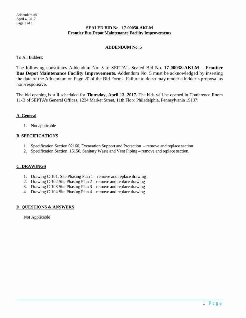
ADDENDUM No. 5 To All Bidders: The following constitutes Addendum No. 5 to SEPTA’s Sealed Bid No. 17-00038-AKLM – Frontier Bus Depot Maintenance Facility Improvements. Addendum No. 5 must be acknowledged by inserting the date of the Addendum on Page 20 of the Bid Forms. Failure to do so may render a bidder’s proposal as non-responsive. The bid opening is still scheduled for Thursday, April 13, 2017. The bids will be opened in Conference Room 11-B of SEPTA's General Offices, 1234 Market Street, 11th Floor Philadelphia, Pennsylvania 19107. A. General
1. Not applicable B. SPECIFICATIONS
1. Specification Section 02160, Excavation Support and Protection – remove and replace section 2. Specification Section 15150, Sanitary Waste and Vent Piping – remove and replace section.
C. DRAWINGS
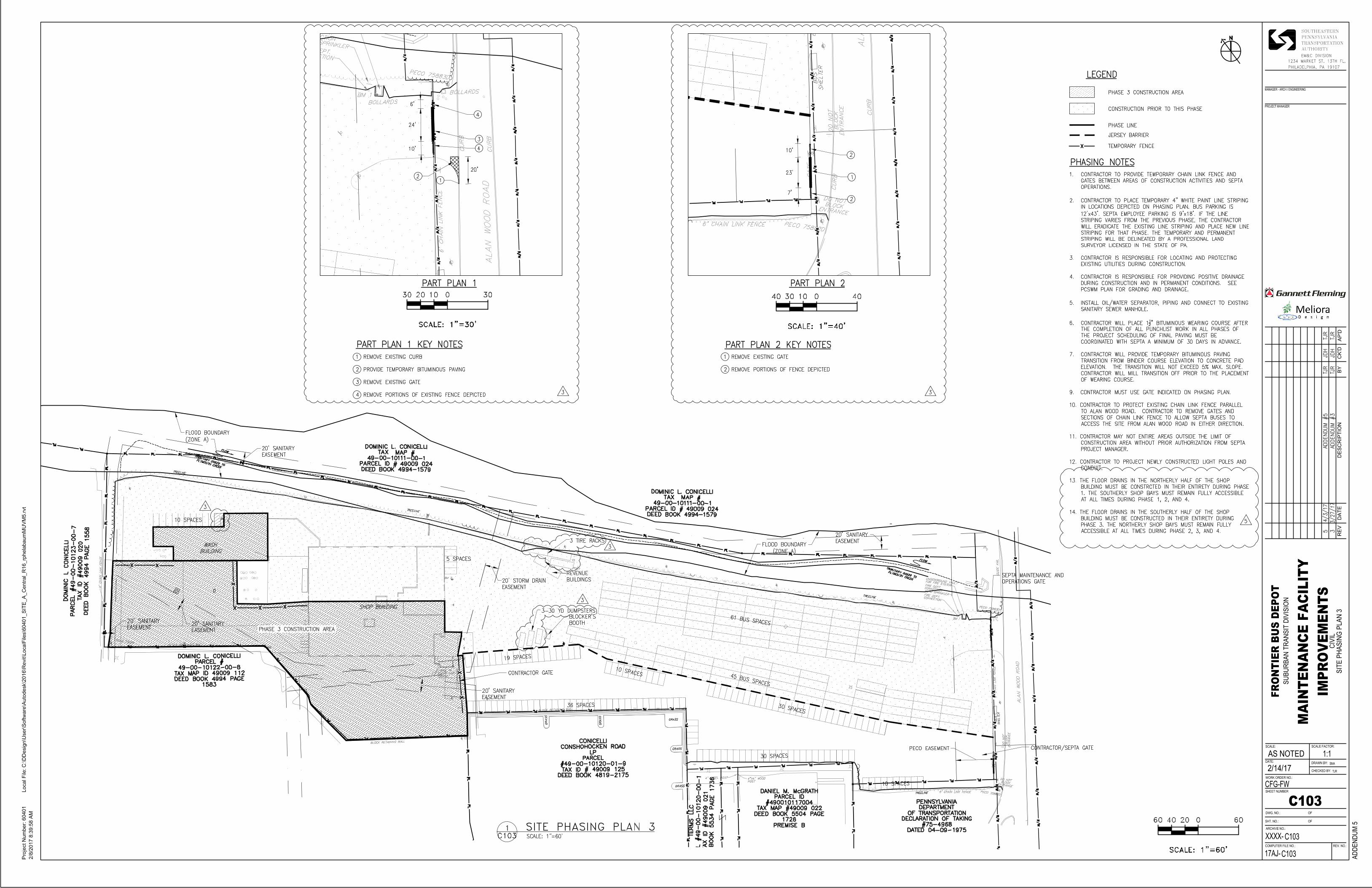
1. Drawing C-101, Site Phasing Plan 1 – remove and replace drawing 2. Drawing C-102 Site Phasing Plan 2 – remove and replace drawing 3. Drawing C-103 Site Phasing Plan 3 – remove and replace drawing 4. Drawing C-104 Site Phasing Plan 4 – remove and replace drawing
D. QUESTIONS & ANSWERS Not Applicable

4/3/2017 SEPTA Frontier Bus Depot Improvements Addendum No. 5
Excavation Support and Protection 02160-1
SECTION 02160 - EXCAVATION SUPPORT AND PROTECTION
PART 1 GENERAL
1.01 DESCRIPTION OF WORK
A. The work of this section shall consist of the designing, providing, maintaining, and subsequently removing to the extent indicated, of an excavation support system as required to retain earth excavations and embankments in a manner which shall permit the safe and expeditious construction of the permanent structures and utilities and prevent lateral displacement or settlement of adjacent building, structures, and utilities.
B. The support system may include steel sheet piling, underpinning, or other methods as approved by SEPTA, and may be secured in place by shoring, walls, struts, tieback anchors, or other similar means suitable for the site conditions and adjacent structures.
C. Existing foundation drawings for the building are not available. It is the contractor’s responsibility to verify the existing foundation sizes and elevation prior to design of the excavation support system for the rainwater harvesting tank.
D. Based on existing General Structural Notes drawing from Frontier Garage Phase I and II Renovation (dated 07-31-86), the existing building footing minimum bearing capacity is 3,000 psf. Contractor is to verify bearing capacity.
E. Subsurface investigation is required to be performed by the Contractor at the location of the rainwater harvesting system, at a minimum, for the proper design of the excavation support system.
F. Related Sections:
1. Section 02010 – Subsurface Investigation.
2. Section 02190 – Site Monitoring.
3. Section 02200 – Excavation, Backfill, and Compaction.
1.02 REFERENCES
A. Reference Publications are referred to be abbreviation as follows:
1. American Concrete Institute (ACI):
a. ACI 301, Specifications for Structural Concrete.

4/3/2017 SEPTA Frontier Bus Depot Improvements Addendum No. 5
Excavation Support and Protection 02160-2
b. ACI 305, Hot Weather Concreting.
c. ACI 306, Guide to Cold Weather Concreting.
2. American Institute of Steel Construction (AISC).
3. ASTM International (ASTM):
a. ASTM A36, Standard Specification for Carbon Structural Steel.
b. ASTM A328, Standard Specification for Steel Sheet Piling.
c. ASTM A416, Standard Specification for Steel Strand, Uncoated Seven-Wire for Prestressed Concrete.
d. ASTM A421, Standard Specification for Uncoated Stress-Relieved Steel Wire for Prestressed Concrete.
e. ASTM A572, Standard Specification for High-Strength Low-Alloy Columbium-Vanadium Structural Steel.
f. ASTM A722, Standard Specification for Uncoated High-Strength Steel Bar for Prestressing Concrete.
g. ASTM D698, Standard Test Methods for Laboratory Compaction Characteristics of Soil Using Standard Effort (12 400 ft-lbf/ft3 (600 kN-m/m 3)).
4. American Wood Preservers’ Association (AWPA):
a. AWPA C2, Lumber, Timber, Bridge Ties and Mine Ties – Preservative Treatment by Pressure Processes.
5. U.S. Army Corps of Engineers (USACE).
a. USACE CRD-C621, Specification for Non-Shrink Grout.
1.03 QUALITY ASSURANCE
A. Excavation support work shall be performed by a firm having a minimum of 10 years of experience in related work and having successfully completed work on a minimum of two project of a similar nature within the past 5 years.
B. All excavation support system work shall be under the direct supervision of a qualified professional engineer having a minimum of 5 years experience in similar work. Direct field superintendents shall have a minimum of 5 years experience in similar work.

4/3/2017 SEPTA Frontier Bus Depot Improvements Addendum No. 5
Excavation Support and Protection 02160-3
C. At a minimum, a subsurface investigation shall be performed to assess the subsurface conditions expected to be encountered at the location of the rainwater harvesting system. A minimum of one (1) boring is required at this location, with a depth adequate to evaluate the subsurface materials and groundwater conditions over the full depth of the excavation support system and to properly design the system.
D. The support system shall be designed to support earth pressures, building loads, vehicle loads, utility and equipment loads, construction loads, railroad loads, and other surcharge loads as applicable. Provide shoring, bracing, cribbing, underpinning, and sheeting in accordance with SEPTA - ROW Design and Construction Standards.
E. Drawings and calculations shall be stamped and signed by a professional engineer registered in the Commonwealth of Pennsylvania.
F. Comply with local codes and ordinances of governing authorities having jurisdiction.
1.04 SUBMITTALS:
A. Provide the following in a timely manner in accordance with the approved submittals schedule as specified in Section 01401-General Requirements.
1.05 SUBMITTAL: EXCAVATION SUPPORT SYSTEM SHOP DRAWINGS
A. Shop drawings of the excavation support system which shall include the following information:
1. Layout drawings of proposed work.
2. Material specifications.
3. Method of operation and installation, test procedures, and components to be left in place.
4. Detailed schedule of proposed construction operations
5. Method for monitoring movement of existing structures and tracks.
6. Record of experience.
B. Results of subsurface investigations, including complete boring logs, short- and long-term groundwater level readings, and laboratory test results.
C. Complete design calculations, clearly referenced to the drawings and easy to review. Calculations shall include all design loads and the maximum

4/3/2017 SEPTA Frontier Bus Depot Improvements Addendum No. 5
Excavation Support and Protection 02160-4
theoretical deflections of support members. Calculations shall include references and backup materials used to estimate soil and rock parameters for the design.
PART 2 PRODUCTS
2.01 PRODUCTS
A. General: All materials shall be of the size, shape, and properties suitable for supporting the loads imposed. Materials need not be new, but shall be in serviceable condition.
B. Steel Sheet Piling: ASTM A328 or ASTM A572.
C. Concrete:
1. Concrete work shall meet applicable requirements for ACI 301 “specification for structural concrete for buildings,” except as modified by the supplemental requirements specified in this section. Numbers in parentheses refer to ACI 301 paragraphs.
a. (3.2) The 28-day compressive strength of concrete for underpinning or encasement of soldier beams shall be 4,000 pounds per square inch. Lean concrete shall have a 28-day compressive strength of 1,500 pounds per square inch.
b. (3.7.1) Calcium chloride shall not be used. Chloride ions in admixtures shall not exceed 0.1 percent by weight of cement content.
c. (12.3) The recommendations of ACI 305 “Hot Weather Concreting,” and ACI 306 “Cold Weather Concreting” are made a part of this specification.
2. Non-shrink grout shall meet the requirements of the Corps of Engineers’ specification CRD-C621 for non-shrink grout.
D. Structural Steel: Structural steel, including braces, struts, walls, and stiffener plates, shall meet requirements of ASTM A36 and AISC “Specification for Structural Steel Buildings.”
E. Tieback tendons shall be fabricated from single or multiple elements meeting the requirements of the following standards:
1. Steel Bars: ASTM A722.
2. Seven-Wire Strand: ASTM A416.

4/3/2017 SEPTA Frontier Bus Depot Improvements Addendum No. 5
Excavation Support and Protection 02160-5
3. Wires: ASTM A421.
F. Timber Lagging: Preservative treated timber lagging shall be treated in accordance with AWPA C2 and shall be of a structural grade providing a minimum allowable bending of 1,100 pounds per square inch.
PART 3 EXECUTION
3.01 SITE CONDITIONS
A. Monitor adjacent tracks and structures in accordance with Section 02190, and SEPTA – ROW Design and Construction Standards. Provide a contingency plan to be implemented if unfavorable performance is evidenced.
B. Protect existing structures and existing active sewer, water, gas, electricity, and other utility services and structures. Comply with requirements of governing authorities and agencies for protection, relocation, removal, and discontinuation of services, as affected by this work.
C. Sheeting, Shoring, and Bracing
1. The Contractor shall adhere to the requirements for sheeting and shoring as defined in the SEPTA – ROW Design and Construction Standards. The most stringent requirements shall govern.
2. Protect the site from caving and detrimental soil movement.
3. The bottom of the support system shall be carried to a depth below the main excavation adequate to prevent lateral movement. In areas where additional excavation is required below the main excavation sub grade, provision shall be made to minimize movement of the main excavation supports.
4. Sheeting, shoring, and bracing systems retaining earth on which the support or stability of existing structures is dependent shall be left in place at completion of work. Leave components in place as indicated on the shop drawings.
5. Locate sheeting, shoring, and bracing to clear permanent work and to permit forming and finishing of concrete surfaces and installation of utilities. If necessary to move a brace, install new, comparable bracing prior to removal of original brace.
6. Do not place sheeting, shoring, or bracing where it will be cast into or included in permanent concrete work except as otherwise indicated or approved.
4/3/2017 SEPTA Frontier Bus Depot Improvements Addendum No. 5
Excavation Support and Protection 02160-6
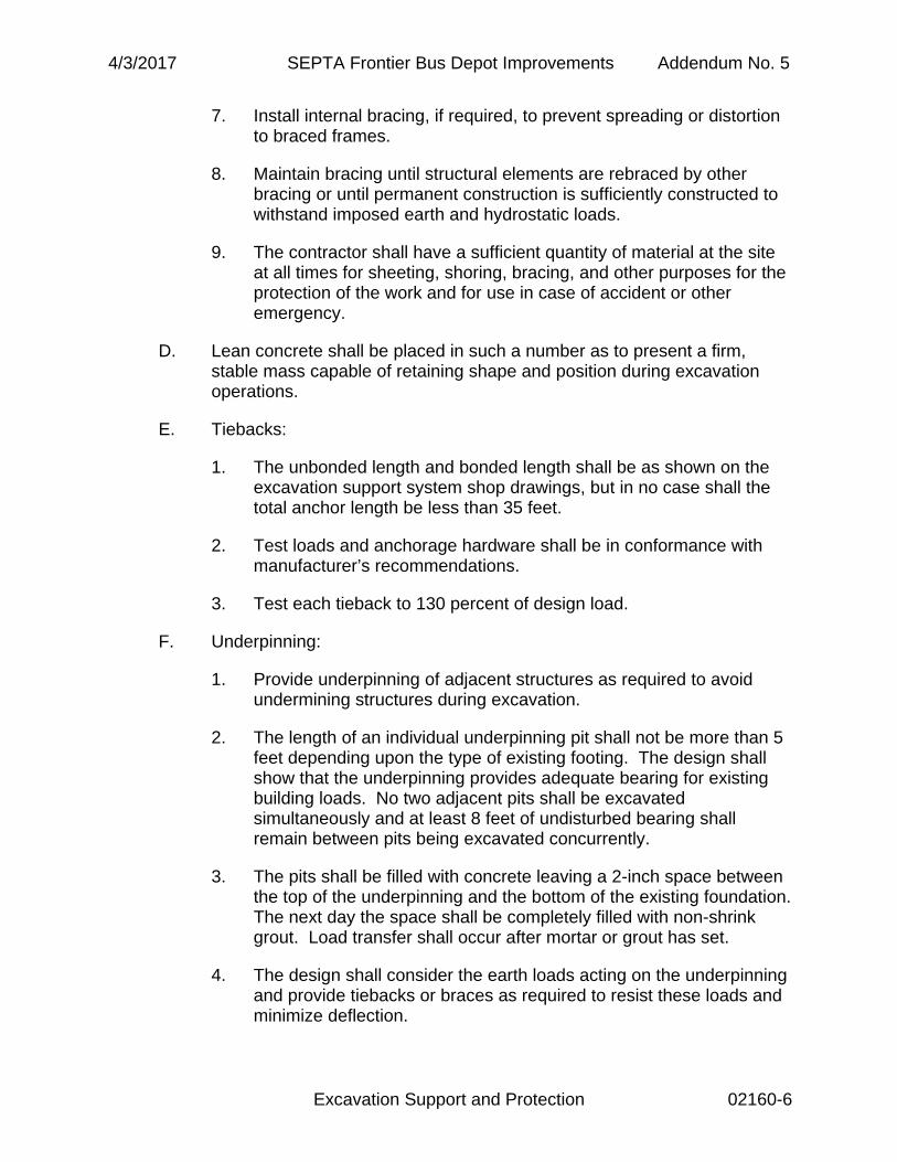
7. Install internal bracing, if required, to prevent spreading or distortion to braced frames.
8. Maintain bracing until structural elements are rebraced by other bracing or until permanent construction is sufficiently constructed to withstand imposed earth and hydrostatic loads.
9. The contractor shall have a sufficient quantity of material at the site at all times for sheeting, shoring, bracing, and other purposes for the protection of the work and for use in case of accident or other emergency.
D. Lean concrete shall be placed in such a number as to present a firm, stable mass capable of retaining shape and position during excavation operations.
E. Tiebacks:
1. The unbonded length and bonded length shall be as shown on the excavation support system shop drawings, but in no case shall the total anchor length be less than 35 feet.
2. Test loads and anchorage hardware shall be in conformance with manufacturer’s recommendations.
3. Test each tieback to 130 percent of design load.
F. Underpinning:
1. Provide underpinning of adjacent structures as required to avoid undermining structures during excavation.
2. The length of an individual underpinning pit shall not be more than 5 feet depending upon the type of existing footing. The design shall show that the underpinning provides adequate bearing for existing building loads. No two adjacent pits shall be excavated simultaneously and at least 8 feet of undisturbed bearing shall remain between pits being excavated concurrently.
3. The pits shall be filled with concrete leaving a 2-inch space between the top of the underpinning and the bottom of the existing foundation. The next day the space shall be completely filled with non-shrink grout. Load transfer shall occur after mortar or grout has set.
4. The design shall consider the earth loads acting on the underpinning and provide tiebacks or braces as required to resist these loads and minimize deflection.

4/3/2017 SEPTA Frontier Bus Depot Improvements Addendum No. 5
Excavation Support and Protection 02160-7
G. Removal of Support System
1. Remove all support systems prior to placement of backfill. Where the support of excavation system is removed, wholly or in part, the removal shall be performed in a manner that will not disturb or damage adjacent buildings, structures, construction, or utilities. All voids shall be immediately filled with lean concrete or with an approved backfill compacted to density equal to 100 percent of the density at optimum moisture content as determined by ASTM D698.
2. All material removed from the supporting system shall be immediately removed from the site.
3. The contractor shall repair all damage, which results from removal of the supporting system.
END OF SECTION

4/3/2017 SEPTA Frontier Bus Depot Improvements Addendum No. 5
Excavation Support and Protection 02160-8
THIS PAGE INTENTIONALLY LEFT BLANK

4/3/2017 Frontier Bus Depot Addendum No. 5 Maintenance Facility Improvements
SANITARY WASTE AND VENT PIPING 15150-1
SECTION 15150
SANITARY WASTE AND VENT PIPING
PART 1 GENERAL
1.01 SUMMARY
A. Section Includes: The work specified in this Section consists of constructing the sanitary and vent piping systems including the basic control devices within the piping systems.
1.02 RELATED SECTIONS
A. Drawings and general provisions of the Contract, including General and Supplementary Conditions and Division 1 Specification Sections, apply to this Section.
B. Supports, Anchors, and Seals: Section 15060.
C. Mechanical Identification: Section 15075
1.03 SUBMITTALS
A. Product Data:
1. Pipe and Fittings.
1.04 QUALITY ASSURANCE (NOT USED)
1.05 REFERENCES
A. American National Standards Institute (ANSI):
1. ANSI B16.23; Cast Copper Alloy Solder Joint Drainage Fittings -- DWV.
2. ANSI B16.29; Wrought Copper and Wrought Copper Alloy Solder-Joint Drainage Fittings -- DWV.
B. American Society for Testing and Materials (ASTM):
1. ASTM C 564; Specification for Rubber Gaskets for Cast Iron Soil Pipe and Fittings.
1.2. ASTM A48; Standard Specification for Gray Iron Castings
4/3/2017 Frontier Bus Depot Addendum No. 5 Maintenance Facility Improvements
SANITARY WASTE AND VENT PIPING 15150-2
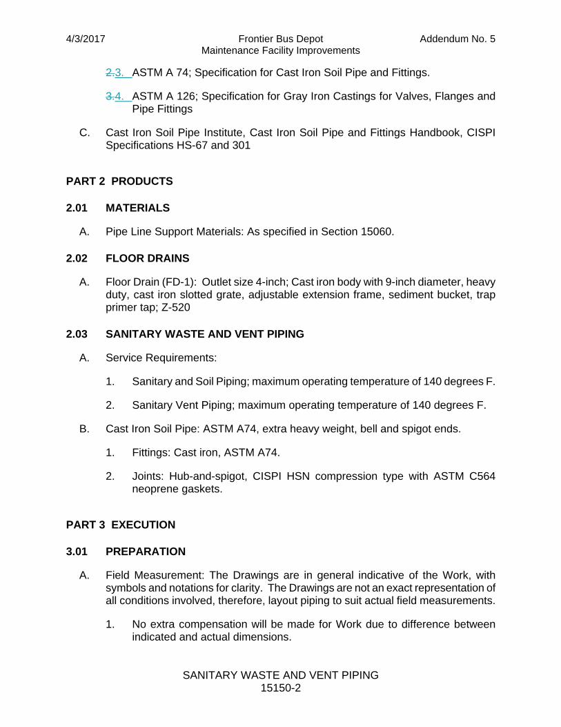
2.3. ASTM A 74; Specification for Cast Iron Soil Pipe and Fittings.
3.4. ASTM A 126; Specification for Gray Iron Castings for Valves, Flanges and Pipe Fittings
C. Cast Iron Soil Pipe Institute, Cast Iron Soil Pipe and Fittings Handbook, CISPI Specifications HS-67 and 301
PART 2 PRODUCTS
2.01 MATERIALS
A. Pipe Line Support Materials: As specified in Section 15060.
2.02 FLOOR DRAINS
A. Floor Drain (FD-1): Outlet size 4-inch; Cast iron body with 9-inch diameter, heavy duty, cast iron slotted grate, adjustable extension frame, sediment bucket, trap primer tap; Z-520
2.03 SANITARY WASTE AND VENT PIPING
A. Service Requirements:
1. Sanitary and Soil Piping; maximum operating temperature of 140 degrees F.
2. Sanitary Vent Piping; maximum operating temperature of 140 degrees F.
B. Cast Iron Soil Pipe: ASTM A74, extra heavy weight, bell and spigot ends.
1. Fittings: Cast iron, ASTM A74.
2. Joints: Hub-and-spigot, CISPI HSN compression type with ASTM C564 neoprene gaskets.
PART 3 EXECUTION
3.01 PREPARATION
A. Field Measurement: The Drawings are in general indicative of the Work, with symbols and notations for clarity. The Drawings are not an exact representation of all conditions involved, therefore, layout piping to suit actual field measurements.
1. No extra compensation will be made for Work due to difference between indicated and actual dimensions.

4/3/2017 Frontier Bus Depot Addendum No. 5 Maintenance Facility Improvements
SANITARY WASTE AND VENT PIPING 15150-3
2. Submit to the Engineer for approval, details of proposed departures necessitated by field conditions or other causes.
B. Interferences: Layout piping systems to compensate for structural interferences, to preserve headroom, and not to interfere with openings, passageways and equipment. Do not install piping with joints and fittings over motors, switchboards, panels, or similar electrical apparatus.
3.02 TRENCH DRAIN GRATE AND FRAME
A. Acceptable Manufacturers:
1. Neenah Foundry
2. US Foundry and Manufacturing Corp.
3. Zurn
4. Or Approved Equal
B. Heavy duty cast iron trench drain grate and frame suitable for bus wheel loading.
1. Cast iron: ASTM A48, Class 35B
2. Load: AASHTO H-20
3. Slotted grate openings parallel to the short axis of the drain grate.
4. Grate Frame: Drain grate frame with integral anchors for cast in place installation.
3.023.03 SANITARY AND WASTE PIPE INSTALLATION
A. General Requirements: The schematic drawings do not necessarily indicate every piping size or alignment. Provide the required pipe fittings, adapters, etc. as required to construct complete piping systems.
1. Install piping concealed in those areas of the structures having hung ceilings and exposed in all other areas, except where indicated otherwise on the Drawings.
2. Clean piping prior to installation and following installation to prepare for painting.
3. Keep open ends of piping and pipe attachment openings on equipment capped or plugged until actual connections.

4/3/2017 Frontier Bus Depot Addendum No. 5 Maintenance Facility Improvements
SANITARY WASTE AND VENT PIPING 15150-4
4. Construct pipe runs from full lengths of pipe using short sections only for runs of less than full pipe length. Make changes in directions of pipe runs with fittings only.
5. Cut pipes accurately to measurements established in the field and assemble in place without springing, forcing, excessive cutting or weakening of the structure.
6. Provide increasing fittings where increases in pipe sizes is necessary.
7. Pipe Supports Installation: Place and support piping runs as specified in Section 15060.
8. Piping Pitch: Unless otherwise indicated, pitch piping not less than one inch in eight feet.
B. Soil or Waste Piping Installation Requirements:
1. Changes in Direction: Make changes in direction in soil or waste piping using the appropriate sanitary fittings according to the adopted Plumbing Code; except that sanitary tees may be used on vertical stacks, and short quarter bends or elbows may be used where the change in direction of flow is from horizontal to vertical.
2. Traps: Provide a trap at the connection of each plumbing fixture, drain and piece of equipment requiring connection to soil or waste piping except where noted on the Drawings. Install traps as close as possible to the fixture, drain or piece of equipment; double trapping not permitted.
3. Sleeve and seal penetrations trough foundation wall.
C. Exposed Piping: Install exposed piping parallel or perpendicular to the lines of the building structure and to compensate for structural interferences, to preserve headroom, and not to interfere with openings, passageways and equipment.
1. Install piping a sufficient distance from other work to permit clearance of not less than one inch between the piping or insulated piping and adjacent work.
2. Install piping as close as possible to walls, overhead construction, columns, and similar to facilitate insulating work and removal of piping later.
3.033.04 VENT PIPE INSTALLATION
A. General Requirements: The schematic drawings do not necessarily indicate every piping size or alignment. Provide the required pipe sizes, fittings, adapters, etc. as required to construct complete piping systems.

4/3/2017 Frontier Bus Depot Addendum No. 5 Maintenance Facility Improvements
SANITARY WASTE AND VENT PIPING 15150-5
1. Install piping concealed in those areas of the structures having hung ceilings and exposed in all other areas, except where indicated otherwise on the Drawings.
2. Clean piping prior to installation.
3. Construct pipe runs from full lengths of pipe using short sections only for runs of less than full pipe length. Make changes in directions of pipe runs with fittings only.
4. Cut pipes accurately to measurements established in the field and assemble in place without springing, forcing, excessive cutting or weakening of the structure.
5. Provide increasing fittings where increases in pipe sizes is necessary.
6. Pipe Supports Installation: Place and support piping runs as specified in Section 15060.
B. Vents Piping Installation Requirements:
1. Extend vent pipes to not less than 10 inches nor more than 16 inches above the roof. Coordinate the installation of vent pipe in accordance with current Plumbing Codes or as follows:
2. Where vents are taken on horizontal runs of soil or waste piping make such connections above the center line of the piping, either on the top or at 45 degree angle.
3.043.05 PIPE JOINING
A. General Requirements: Exercise care when making pipe joints and make joints in accordance with the pipe material manufacturer's recommendations and the following additional requirements.
1. In each instance of pipe joining, those portions of pipes involved must be absolutely clean just prior to assembly.
2. If a joint is extremely difficult to assemble or is not completely sealed, disassemble the joint and correct the difficulty if possible. Remake the joint using new materials when necessary.
B. Cast Iron Soil Pipe Joints:
1. Compression Joints: Make compression (gasket) joints in cast iron hub and spigot pipe in accordance with procedures outlined in CISPI 301.

4/3/2017 Frontier Bus Depot Addendum No. 5 Maintenance Facility Improvements
SANITARY WASTE AND VENT PIPING 15150-6
2. Caulked: Cast iron hub and spigot pipe ends must be fully entered prior to making oakum/lead joint. Make oakum/lead caulk joints in accordance with procedures outlined in CISPI 301.
3.053.06 FIELD QUALITY CONTROL
A. General Requirements: Conduct tests specified under Part 3 Execution, so that each piping system installed in the Project is tested to the Engineer's satisfaction.
1. Provide tools, materials (including clean water), apparatus and instruments necessary for piping system testing.
2. Free piping systems of trapped air for tests involving water.
3. Perform tests involving water when there is no danger of water freezing during the test time period.
4. Repair and Retest: When a piping system fails to meet test requirements specified herein, conform to the following:
a. Determine source or sources of leakage.
b. Repair or replace defective material and if a result of improper workmanship, correct such.
c. Conduct additional tests to demonstrate that piping system meets specified test requirements.
d. Perform repair and retest work at no increase in Contract Price.
5. Accuracy Proof: Furnish acceptable proof to the Engineer that testing apparatus, pressure gauges, etc. have been recently checked and calibrated, as applicable, prior to use on this Project.
B. Testing: Ten foot head hydrostatic; 15 minute test duration time, and until an examination is made to determine each joint and connection are leak free.
1. Plug all system openings except the highest opening, and fill system with water to the point of overflow.
2. When testing by sections plug all openings except the highest opening in the section under test and fill sections with water. No section shall be tested with less than ten-foot head hydrostatic and a 15-minute test duration time. In testing successive sections, include the upper ten feet of the next section preceding section in the test so no joints are tested at less then ten-foot of head of water.
4/3/2017 Frontier Bus Depot Addendum No. 5 Maintenance Facility Improvements
SANITARY WASTE AND VENT PIPING 15150-7
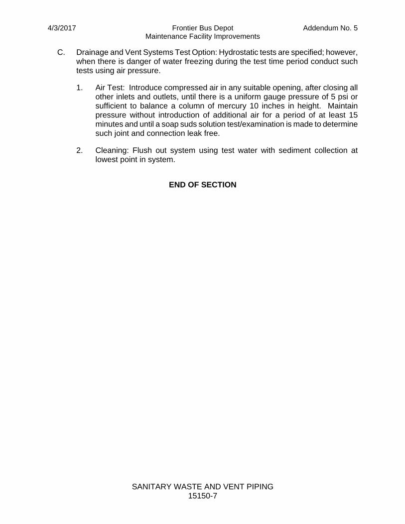
C. Drainage and Vent Systems Test Option: Hydrostatic tests are specified; however, when there is danger of water freezing during the test time period conduct such tests using air pressure.
1. Air Test: Introduce compressed air in any suitable opening, after closing all other inlets and outlets, until there is a uniform gauge pressure of 5 psi or sufficient to balance a column of mercury 10 inches in height. Maintain pressure without introduction of additional air for a period of at least 15 minutes and until a soap suds solution test/examination is made to determine such joint and connection leak free.
2. Cleaning: Flush out system using test water with sediment collection at lowest point in system.
END OF SECTION

Lo
ca
l F
ile
:
ARCHIVE NO.:
SHEET NUMBER
DWG. NO.:
OF
OF
SHT. NO.:
REV. NO.:
SCALE:
DRAWN BY:DATE:
WORK ORDER NO.:
SCALE FACTOR:
CHECKED BY:
COMPUTER FILE NO.:
SOUTHEASTERNPENNSYLVANIATRANSPORTATIONAUTHORITY
AP
'D
AS NOTED
2/8
/2
01
7 8
:3
9:5
8 A
M
C:\D
De
sig
n\U
se
r\S
oftw
are
\A
uto
de
sk\2
01
6\R
evit\L
oca
lF
ile
s\6
04
01
_S
IT
E_
A_
Ce
ntra
l_
R1
6_
rp
he
la
ba
um
MU
VM
5.rvt
Pro
je
ct N
um
be
r: 6
04
01
2/14/17
ADDE
NDUM
5
RE
VD
AT
ED
ES
CR
IP
TIO
NB
YC
K'D