department of transportation manual change … · ... typical traffic signal installation,...
TRANSCRIPT

Attached is a revised portion of Chapter 9 of the Traffic Manual for new Section 9-01.5, BicycleSignals, and the updating of Section 9-03.3, Selection of Left-Turn Phasing, Section 9-03.7, ThreePhase Operation, Section 9-03.8, Permissive Left-Turn Phasing, Section 9-03.12, Location of SignalFaces, Section 9-03.15, Right-Turn Arrows, Section 9-03.24, Vehicle Detectors, Section 9-03.26,Bicycle Detectors, Section 9-03.27, Signal Plan Schedules, Section 9-03.35, Temporary Signals forHaul Roads, Section 9-04.1, Introduction (Traffic Signal Operations), Section 9-04.2, Review ofTraffic Signal Operations, Section 9-04.5, Yellow Change Intervals, Table 9-1, Suggested DetectorSetbacks From Limitline, Figure 9-22, Typical Traffic Signal Installation, Section 9-05.1, Introduction(Flashing Beacons), Section 9-05.2, Signal Ahead Flashing Beacons, Section 9-12.2, RoadwayLuminaires and Section 9-13.11, Voltage Drop. This also replaces existing Title Page, Table ofContents and pages 9-6, 9-24 through 9-40, 9-58, 9-61, 9-62, 9-74, 9-80 and 9-81 dated July, 1996.
This manual change should be implemented on all new construction and during routine maintenanceoperations. The following is an explanation of those sections that are changed:
• Section 9-01.5 - Bicycle Signals. This new section has been added to Section 9-01, Traffic Signals,Basic Information and Warrants to address operational problems involving bicycles.
• Section 9-03.8 - Permissive Left-Turn Phasing. This section has been revised to include the use ofa Left Turn Yield extinguishable message sign on local roads in place of the R73-7, at signalizedintersections that have protected-permissive or permissive-protected left-turn phasing.
• Sections 9-03.9 through 9-03.30 have been repositioned on pages 9-26 through 9-32 to accommo-date the revision to Section 9-03.8.
• Section 9-03.26 - The reference to Standard Plan ES-5D is corrected to ES-5B.
• Section 9-04.5 - The Approach Speed is changed to reflect both English and Metric speeds and theYellow Intervals have been revised.
• Table 9-1, Suggested Detector Setbacks From Limitline, is changed to reflect both English and Metricspeeds. The formulas and the corresponding table have also been revised.
manual change transmittalCALIFORNIADEPARTMENT OF TRANSPORTATIONDAS-MA-3
TITLE
SUBJECT AREA
SUPERSEDES
APPROVED DATEISSUED
ISSUING UNIT
PAGE OF
DISTRIBUTION
All Manual Holders
NO.
Traffic Manual
Chapter 9,Traffic Signals and Lighting
Chapter 9, Traffic Signals and LightingPages 9-6, 9-24 through 9-40, 9-58, 9-61, 9-629-74, 9-80 and 9-81.
Traffic Operations Program
11-13-02
1 4
TM03-1
• Figure 9-22, Typical Traffic Signal Installation, reference in Note 8 to Traffic Manual Section 9-20is corrected to Section 9-03.
• Section 9-12.2 - The mounting height for roadway luminaires on conventional highways and atintersections of freeway ramps with surface streets is revised to 9.14 m only.
• Section 9-13.11 - In the Example Equation, the minimum wire size is corrected from No. 8 to No. 6.
The following changes are made to the Traffic Manual at the recommendation of The California Traffic ControlDevice Committee (CTCDC) to improve text that will carry over into the MUTCD California Supplement.
• Section 9-03.3 Selection of Left-Turn PhasingChange the second paragraph that reads: “ If the left turn volume is 300 vehicles per hour or more, considerationshould be given to a two-lane left turn.” to: “If the left turn volume is 300 or more vehicles per hour, or if delays totraffic at the intersection can be significantly reduced, consideration should be given for a two-lane left turn.”
• Section 9-03.7 Three Phase OperationChange the second paragraph that reads: “This operation is the simplest and the least expensive. It can be eitherpretimed or traffic-actuated. Since both left turn approaches receive the same amount of green time simultaneously,regardless of directional demand, less efficient operation will result.” to: “ Three phase operation can be eitherpretimed or traffic-actuated.”
• Section 9-03.8 Permissive Left Turn PhasingChange paragraph 5 that reads: “Local authorities may use an extinguishable message sign on local roads …”to: “Public agencies having jurisdiction may use an extinguishable message sign on local roads…”
• Section 9-03.12 Location Of Signal FacesChange the first paragraph that reads: “On an undivided roadway, the signal faces for each through approachof an intersection are usually placed at the far right and far left corners. The signal faces for two or more approachescan often be combined on a single standard. However, where the curb return radius is greater than 3 m, it may benecessary to locate the signal faces on separate standards to provide maximum visibility for the controlled approach.”to: “On an undivided roadway, the signal faces for each through approach of an intersection are usually placed atthe far right and far left corners. The signal faces for two or more approaches can often be combined on a singlestandard. However, is generally desirable to locate the signal faces on separate standards at curb returns. Thispractice will tend to maximize the visibility of the signal faces for the controlled approach while minimizing the visibilityof the signal faces intended for the cross-street approach. It may be necessary to locate signal faces on separatestandards whenever the curb return radius is greater than 3 m.”
Change the second paragraph that reads: “The preferred locations for new installations of signal faces for fully-protected left turn movements at a typical intersection are on a mast arm of sufficient length to place one signal faceas nearly as practicable in line with the left turn lane …” to: “The preferred locations for new installations of signalfaces for fully-protected left turn movements at a typical intersection are on a mast arm of sufficient length to placeone signal face as nearly as practical in the center of the left turn lane … ”
Page 2 of 4

Page 3 of 4
• Section 9-03.15. Right Turn ArrowChange the third paragraph which reads: “ A right-turn green arrow should be used only when the right-turnvolume exceeds 200 vehicles per hour, or it is the only movement that traffic is permitted to make” to: “A right-turngreen arrow should be considered for use only when there is an exclusive right-turn lane or it is the only movementthat traffic is permitted to make or when the right-turn volume exceeds 200 vehicles per hour.”
• Section 9-03.24 Vehicle DetectorsAdd a new item 5 that reads: “Video Detection - Detects vehicles passing through the field of view of a CCTVcamera or image sensor. They are useful during construction or other temporary situations when lanes changefrequently in width and location as well as where the installation of conduit and detector loops is expensive or difficult.Care is necessary to avoid locations and conditions which could obscure the detector’s visibility such as extremeweather, sun glare and moving shadows.”
• Section 9-03.27 Signal Plan ScheduleChange item # 2 that reads: “A conductor and conduit schedule shows the size of each conduit run, and the sizeand number of conductors in each conduit run.” to: “A conductor and conduit schedule shows the size of each conduitrun, and the size, type and number of conductors or cables in each conduit run.”
• Section 9-03.35 Temporary Signals for Haul Roads or One-Way Control in Construction ZonesChange title in item # 2 that reads: “Permit or Contract Requirements” to: “Requirements”Change item 2d which reads: “Timing of the signals will be determined by the District Traffic Engineer.” to: Timingof the signals will be determined by the Agency having jurisdiction.”
• Section 9-04.1 IntroductionAdd the following sentence to the first paragraph: “Maintenance and operation of highway traffic signalsinvolving State Highways by an agency other than the California Department of Transportation shall require a jointlyapproved written agreement.”
• Section 9-04.2 Review of Traffic Signal OperationChange item # 2 that reads: “Time-of-Day Settings” to: “Time-of-Day or Traffic Responsive Settings”
Change the last paragraph that reads: “Initial timing of traffic signals and any subsequent changes in timing shallbe the responsibility of Traffic Operations. Maintaining the timing is the responsibility of Maintenance. Timing recordsshall be kept in both Maintenance and Traffic Operations.” to: “Initial timing of traffic signals and any subsequentchanges in timing shall be the responsibility of Traffic Operations. Timing records shall be kept and be readilyavailable to maintenance and traffic operations staff and other agencies, where appropriate.”
• Section 9-04.6 Red Clearance IntervalChange the last paragraph that reads: “Generally, red clearance intervals are not required. A red clearanceinterval may be used following the yellow change interval, at very wide intersections, offset intersections, or at otherlocations where it is desirable to delay the green interval for opposing traffic. Normally, red clearance intervals rangefrom 0.01 seconds to 2.0 seconds.” to: “Red clearance intervals which follow yellow change intervals are notrequired, but may be considered where any of the following conditions exist: intersections that are wide, offset orcontain unusual geometry; intersections where the visibility of conflicting traffic is blocked or limited; movements

Page 4 of 4
where the approach speeds are 88 km/hr (55 mph) or more; or where it is desirable to help clear vehicles thatrecurrently become queued in the intersection where there are permissive left turns. Normally, red clearance intervalsrange from 0.01 to 2.0 seconds and should not exceed 6 seconds.”
• Section 9-05.1 IntroductionAdd item #9 that reads: “At Intersections Where a More Visible Warning is Desired”
• Section 9-05.2 Signal Ahead Flashing BeaconChange item #3 that reads : “Any traffic signal with limited approach visibility and where approach speeds exceed80 Km/h (50 mph)”. to: “Any traffic signal with limited approach visibility, or where approach speeds exceed 80Km/h (50 mph)”.
ATTENTION: This hard copy version as well as other chapters of the Traffic Manual may not reflect newor revised policies of the Department of Transportation. To get the latest updates to the entire Traffic Manual,see the "Traffic Operations Program Directive and Policy Memos" web page at <http://www.dot.ca.gov/hq/traffops/signtech/signdel/policy/policy.htm>.

STATE OF CALIFORNIABUSINESS, TRANSPORTATION AND HOUSING AGENCY
DEPARTMENT OF TRANSPORTATION
November, 2002
9-00 - Table of Contents, List of Figures and List of Tables
9-01 - Traffic Signals, Basic Information and Warrants
9-02 - Traffic Signal Development Procedures
9-03 - Traffic Signal Design
9-04 - Traffic Signal Operations
9-05 - Flashing Beacons
9-06 - Highway Safety Lighting
9-07 - Freeway Lighting
9-08 - Conventional Highway Lighting
9-09 - Highway Safety Lighting Development Procedures
9-10 - Highway Safety Lighting Design Standards
9-11 - Lighting Standards
9-12 - Luminaires
9-13 - Conduit, Wiring and Circuits
CHAPTER 9TRAFFIC SIGNALS
AND LIGHTING
TRAFFIC MANUAL
��������
���

11-2002
TRAFFIC SIGNALS AND LIGHTINGTraffic Manual
CHAPTER 9TABLE OF CONTENTS
����������� �����
����
���������������������������������������������������������� ����������������������������������������������
�������������������������������������������������������������������������������
����������������������������������������
��������� �����!"#� �����!"#� �����$%!$�#� �����!"#� �����!"#� �����&������ �����!"#� �����$%!$�#� �����$%!$�#� �����$%!$�#� �����!"#� �����&������ �����!"#� �����$%!$�#� �����&������ ������������� ����
�!"#� �����&������ �����!"#� �����$%!$�#� �����&������ �����&������ �����&������ �����&������ �����&������ �����&������ �����&������ �����&������ �����!"#� ����
��������� �����!"#� �����!"#� ������������� �����&������ �����&������ �����&������ ����
9-0.1
'(���� )� ��*)���)� ���+(,�'�+� �� -�((��')������������������������������������ ���
�%.��/!&.0�%����������������������������������������������������������������������������������������'�$110& )02%$" -$��$%.3�������������������������������������������������������������������� ���
-$��$%. � � ,0%0�!� 4�50&!"$� 4�"!�������������������������������������� ���-$��$%. � � �%.���!6.0�% �1 �%.0%!�!3 '�$110&�������������������������������-$��$%. � � ,0%0�!� 7�/�3.�0$% 4�"!������������������������������������ ���-$��$%. � � )&5��" ���$3��������������������������������������������������������� ���-$��$%. � � 7��2��330�� ,�����%.������������������������������������������� ���-$��$%. � � �&&0/�%. �86��0�%&���������������������������������������������������-$��$%. � � )#3.��3 -$��$%.���������������������������������������������������� ���-$��$%. � � ���0%$.0�% �1 -$��$%.3�������������������������������������������-$��$%. � � ��!� ��!� 4�"!�� -$��$%.���������������������������������������-$��$%. �� � 7�$9 ��!� �"$# -$��$%.������������������������������������ ���-$��$%. �� � 7�$9 ��!� 4�"!�� -$��$%.��������������������������������� ���
!0/�"0%�3 1�� *�1.�'!�% 75$3�3������������������������������������������������������� ���(����$" �1 �803.0%2 )02%$"3������������������������������������������������������������������0&#&"� )02%$"3�������������������������������������������������������������������������������� ���
'(���� )� ��* �4�*+7,��' 7(+�:(�)���������������������� �����%.��/!&.0�%�����������������������������������������������������������������������������������������7��;�&. (�6��.�������������������������������������������������������������������������������� ����7)<� )!��0..$"3����������������������������������������������������������������������������������0%$%&0%2����������������������������������������������������������������������������������������������302% �3.������������������������������������������������������������������������������������ �����%3.�!&.0�% �3.3 � �%��%.0�%$" �025=$#3����������������������������������� �����%3.�!&.0�% �3.3 � ����=$#3������������������������������������������������������������(�$/=$# ��6������%.3 �# *�&$" �2�%&0�3������������������������������������� ������6��$.0�� �2�����%.3����������������������������������������������������������������� �����%20%���0%2 )���0&�3 1�� *�&$" �2�%&0�3������������������������������������������ ����)$"�$2�/ �"�&.�0&$" �>!06��%.��������������������������������������������������������� �����%&��$&5��%. 7���0.3��������������������������������������������������������������������� ����
'(���� )� ��* �)� ��������������������������������������������������������������� �����%.��/!&.0�%�����������������������������������������������������������������������������������������)�"�&.0�% �1 '�$110& )02%$" +6��$.0�%������������������������������������������������ ����)�"�&.0�% �1 *�1.�'!�% 75$30%2��������������������������������������������������������� ����)0�!".$%��!3 �� !$" *�1.���������������������������������������������������������������� ����*�$/�*$2���������������������������������������������������������������������������������������� ����+66�30.� �� +66�30%2��������������������������������������������������������������������� ����
11-2002
TRAFFIC SIGNALS AND LIGHTING Traffic Manual
TABLE OF CONTENTS(Continued)
9-0.2
������� ����� ����
��������������������������������������������������������������������������������������������������������������������������������������������������������������������������������������������������������
���������������������
����������������������������������
'5��� 75$3� +6��$.0�%�������������������������������������������������������������������� ����7���0330�� *�1.�'!�% 75$30%2����������������������������������������������������������� ����*�&$.0�% �1 �%.��""�� $�0%�.3������������������������������������������������������� ����4�50&"� )02%$" �$&�3 $%/ �%/0&$.0�%3������������������������������������������������ �����!���� �1 )02%$" �$&�3������������������������������������������������������������������ ����*�&$.0�% �1 )02%$" �$&�3��������������������������������������������������������������������������= �%/0&$.0�%3��������������������������������������������������������������������������������*�1.�'!�% ����=3���������������������������������������������������������������������������� ����(025.�'!�% ����=3�������������������������������������������������������������������������� ����4��.0&$" ���% ����=3�������������������������������������������������������������������� ����,�!%.0%2 ��025.3 � 4�50&"� )02%$" �$&�3����������������������������������������������)02%$" �$&� 4030�0"0.# �%.��"����������������������������������������������������������� �����$&96"$.�3�������������������������������������������������������������������������������������� ����7�/�3.�0$% )02%$" �$&�3������������������������������������������������������������������� ����'#6�3 �1 7�/�3.�0$% )02%$" �$&�3�����������������������������????�������� ����,�!%.0%2 ��025.3 � 7�/�3.0$% )02%$" �$&�3????????������ �����.�&.��3?????????????????????���� ����4�50&"� �.�&.��3??????????????????���� ����7�/�3.�0$% �.�&.��3????????????????������� �����0&#&"� �.�&.��3??????????????????���� ����)02%$" 7"$% )&5�/!"�3��??????????????������������ ����7����6.0�%????????????????????����������($0"��$/ 7����6.0�%????????????????�������� ��������2�%&# 4�50&"� 7����6.0�%????????????�������������!3@'�$%30. 4�50&"� 7�0��0.#??????????????����������,�/010&$.0�% �1 �803.0%2 )02%$"3????????????�������� ����)02%$"3 �% 7�"�3 +=%�/ �# +.5��3?????????�������������� �����//0.0�%$" $6$&0.# $. )02%$"0A�/ �%.��3�&.0�%3??????��������� ����'��6��$�# )02%$"3 1�� �$!" (�$/3 ��+%��-$# '�$110& �%.��" 0% �%3.�!&.0�% B�%�3????�������������� ����*$%��:3� �%.��" )02%$"3??????????????�������� ����($�6 ,�.��0%2 )02%$"3????????????????���� ����)02%$"3 $. ,��$�"� ��0/2�3?????????????��������������
'(���� )� ��* +7�(�'�+�)???????????�������� �����%.��/!&.0�%???????????????????�������������(��0�= �1 '�$110& )02%$" +6��$.0�%3??????????��������� ����)02%$"3 $. �%.��&5$%2�3???????????????�������������'0�0%2 �1 ���% �%.���$"3??????????????��������� ����C�""�= 5$%2� �%.���$"3???????????????������ ����
��������� ������������� �����!"#� �����!"#� �����$%!$�#� ������������� �����$%!$�#� �����!"#� ������������� �����&������ �����!"#� �����!"#� �����&������ �����&������ �����$%!$�#� �����!"#� �����&������ ������������� �����!"#� ������������� ������������� �����&������ �����!"#� �����$%!$�#� �����&������ �����&������ �����&������ �����!"#� ����
��������� �����&������ �����&������ �����&������ ����
��������� ������������� ������������� �����&������ �����&������ ������������� ����

11-2002
TRAFFIC SIGNALS AND LIGHTINGTraffic Manual 9-0.3
TABLE OF CONTENTS(Continued)
������� ����� ����
�������������������������������
������������������������������������������������������������������������������������������������������������������
����������
����������������
����������������
����
������������
(�/ "�$�$%&� �%.���$"3???????????????�����������+6��$.0�% �1 7�/�3.�0$% �%/0&$.0�%3???????????�����������!/0�"� 7�/�3.�0$% )02%$"3��������������������������������������������������������������� �����%.0%!0.# �1 +6��$.0�%???????????????������� �����"$350%2 +6��$.0�%?????????????????������ ����
�*�)��� ���+�)??????????????�������������� �����%.��/!&.0�%??????????????????�����������������)02%$" �5�$/ �"$350%2 ��$&�%3???????????�����������������302%?????????????????????��������������0%$%&0%2????????????????????���?������-$�%0%2 �� (�2!"$.��# )02% �"$350%2 ��$&�%��???��������������������� �����0%$%&0%2???????????????????������������������"$350%2 ��$&�%3 $. )&5��" ��33=$"93????????���?��������)6��/ *0�0. )02% �"$350%2 ��$&�%3???????????������ �����%.��3�&.0�% �%.��" �"$350%2 ��$&�%3??????????�����������0%$%&0%2?????????????????????����������"$350%2 ��$&�%3 1�� �0�� ).$.0�%3???????????������� �����0%$%&0%2���������������������������������������������������������������������������������������������).�6 )02% �"$350%2 ��$&�%3������������������������������������������������������������� �����0%$%&0%2����������������������������������������������������������������������������������������������"$350%2 ��$&�%3 $. �!3 ).�63 �% ����=$# �%.��&5$%2�3??��������� �����302% $%/ +6��$.0�%3???????????????�������� �����0%$%&0%2?????????????????????���������
�� �-�C )���'C *� �'�� ???????????����������� �����%.��/!&.0�%???????????????????�������������
�(��-�C *� �'�� ???????????????������?� ���� �%��$"??????????????????????��� ����-$��$%.3?????????????????????����� ����
+�4��'�+��* �� �-�C *� �'�� ???????��������������� �%��$"?????????????????????��?� ����-$��$%.3????????????????????��������� ����
�� �-�C )���'C *� �'�� �4�*+7,��' 7(+�:(�)������������������������������������������������������ ����
�%��$"??????????��������������������������������������������������� ����7��;�&. (�6��.???????????????????���� ����
��������� �����!"#� �����!"#� �����!"#� �����!"#� ����
��������� ������������� ������������� �����!"#� �����&������ �����!"#� �����!"#� �����$%!$�#� �����&������ �����$%!$�#� �����&������ �����&������ �����&������ �����!"#� �����&������ �����&������ �����!"#� �����&������ ����
�&������ �����&������ ����
�&������ �����&������ �����&������ ����
�&������ �����&������ �����&������ ����
�$%!$�#� �����&������ �����&������ ����

11-2002
TRAFFIC SIGNALS AND LIGHTING Traffic Manual
TABLE OF CONTENTS(Continued)
������� ����� ����
������������������������������
����������������������������������������������������
����������������������������
����������������������������
�������������������������������������������������������������������������������
���/0%$.0�% -0.5 :.0"0.# ��6$%0�3????????��������������� ����7"$%3� ���/0%$.0�% $%/ 7��&�330%2??????????��?��� �����0%$%&0%2?????????????????????���������*025.0%2 �# *�&$" �2�%&0�3 �� +.5��3??????????�����������(�&�%3.�!&.0�% �1 �803.0%2 �$&0"0.0�3??????????���������� ����
�� �-�C )���'C *� �'�� �)� � )'���()?������������ ���� �%��$"??????????????????????��� ��������=$# ($�63 $%/ �%%�&.0�%3???????????�������� �����%��%.0�%$" �025=$#3???????????????������� ����)02% *025.0%2???????????????????�?�������'!%%�" *025.0%2???????????????????���� �����$"3�=��9 *025.0%2?????????????????������ �����!3 ).�6 *025.0%2?????????????????�������� ����7$�9�$%/�(0/� *�. *025.0%2?????????????��?��� ����
*� �'�� )'���()??????????????�����?� ���� �%��$"??????????????????��������������?� ����'#6�3� �66"0&$.0�% $%/ ,$3. ��� *�%2.53?????����������?�����������!%/$.0�%3???????????????????���?� ����)"06 �$3�3?????????????????????��� ����
*:,����(�)????????????????????����� ���� �%��$"????????????????????����������� ����(�$/=$# *!�0%$0��3????????????????������� ����)�110. *!�0%$0��3??????????????????����������-$"" *!�0%$0��3�����������������������������������������������������������������������������������
+�:�'� -�(�� �� �(:�')?????????���������� �����%.��/!&.0�%???????????????????���?�������%/!0.?????????????????????������� ����'#6�3 �1 �%/!0.?????????????????���?�������%/!0. )0A�??????????????????��??�������%/!0. �0""???????????????????����?� �����%/!0. �% ).�!&.!��3??????????????��������?�� ����7!"" ��8�3???????????????????����������� �����%3.$""$.0�% �1 7!"" ��8�3??????????????���������� ����7!"" ��8 )0A�???????????????????������� ����-0�0%2?????????????????????����?� ����4�".$2� ��6?????????????????�����?����� ����0�&!0. 4�".$2�3??????????????????�����������
�&������ �����$%!$�#� �����&������ �����&������ �����&������ ����
�!"#� �����$%!$�#� �����&������ �����!"#� �����&������ �����!"#� �����&������ �����&������ �����!"#� ����
�!"#� �����&������ �����!"#� �����!"#� �����!"#� ����
��������� �����&������ ������������� �����$%!$�#� �����$%!$�#� ����
��������� �����&������ �����&������ �����&������ �����!"#� �����&������ �����!"#� �����&������ �����!"#� �����$%!$�#� �����&������ ������������� �����$%!$�#� ����
9-0.4

11-2002
TRAFFIC SIGNALS AND LIGHTINGTraffic Manual 9-0.5
CHAPTER 9LIST OF FIGURES
���� �������������
�������������������������������������������
����
����
����
������������������������������������������������
'�$110& )02%$" -$��$%.3�������������������������������������������������������������������������������'�$110& )02%$" -$��$%.3�������������������������������������������������������������������������������'�$110& )02%$" -$��$%.3�������������������������������������������������������������������������������'�$110& )02%$" -$��$%.3��������������������������������������������������������������������������������)&5��" 7��.�&.0�% -$��$%.3�������������������������������������������������������������������� ������!� ��!� 4�"!�� -$��$%. D:��$% ���$3E��������������������������������������������� ������!� ��!� 4�"!�� -$��$%. D(!�$" ���$3E���������������������������������������������������7�$9 ��!� 4�"!�� -$��$%. D:��$% ���$3E�������������������������������������������������7�$9 ��!� 4�"!�� -$��$%. D(!�$" ���$3E���������������������������������������������� ����0��&.0�%$" '�$110& �!%. )5��.��������������������������������������������������������������������*�1.�'!�% 75$30%2 ,�.5�/3 D75$3� 0$2�$�3E����������������������������������������� �����0&#&"� �.�&.0�% )#3.��3���������������������������������������������������������������������� ����'#60&$" )02%$" *$#�!. $. +113�. �%.��3�&.0�%3D)02%$"0A�/ $%/ ,$�9�/ $3 $ )0%2"� �%.��3�&.0�%E������������������������������������������'#60&$" )02%$" *$#�!. $. +113�. �%.��3�&.0�%3D)02%$"0A�/ $%/ ,$�9�/ $3 $ )0%2"� �%.��3�&.0�%E������������������������������������������'#60&$" )02%$" *$#�!. $. +113�. �%.��3�&.0�%3D)02%$"0A�/ $%/ ,$�9�/ $3 )�6$�$.� �%.��3�&.0�%3E���������������������������������� ����'#60&$" )02%$" *$#�!. $. +113�. �%.��3�&.0�%3D)02%$"0A�/ $%/ ,$�9�/ $3 )�6$�$.� �%.��3�&.0�%3E���������������������������������� ����'#60&$" )02%$" *$#�!. D'=� 75$3� +6��$.0�%E����������������������������������������� ����'#60&$" )02%$" *$#�!. D'5��� 75$3� +6��$.0�%E��������������������������������������� ����'#60&$" )02%$" *$#�!. D�0�� 75$3� F!$" *�1.F +6��$.0�%E������������������������ ����'#60&$" )02%$" *$#�!. D)08 75$3� F+66�30%2F +6��$.0�%E������������������������� ����'#60&$" )02%$" *$#�!. D�025. 75$3� FG!$/ *�1.F +6��$.0�%E��������������������������'#60&$" '�$110& )02%$" �%3.$""$.0�%������������������������������������������������������������������7�"� $%/ �>!06��%. )&5�/!"������������������������������������������������������������������ �����%/!&.�� $%/ �%/!0. )&5�/!"������������������������������������������������������������� ��������=$# *025.0%2������������������������������������������������������������������������������������ ��������=$# *025.0%2������������������������������������������������������������������������������������ �����%.��3�&.0�% *025.0%2�������������������������������������������������������������������������������� �����%.��3�&.0�% *025.0%2�������������������������������������������������������������������������������� ����
�!"#� �����!"#� �����$%!$�#� �����!"#� �����!"#� �����$%!$�#� �����$%!$�#� �����$%!$�#� �����$%!$�#� �����!"#� �����$%!$�#� �����!"#� ����
�!"#� ����
�!"#� ����
�$%!$�#� ����
�$%!$�#� �����$%!$�#� �����&������ �����$%!$�#� �����&������ �����$%!$�#� ������������� �����!"#� �����!"#� �����!"#� �����&������ �����&������ �����&������ ����

11-2002
TRAFFIC SIGNALS AND LIGHTING Traffic Manual9-0.6
CHAPTER 9LIST OF TABLES
���� ������������
���������
���
���������������
)!22�3.�/ �.�&.�� )�.�$&93 ���� *0�0."0%�������������������������������������������� ����'�$110& )02%$" '0�0%2 �%$"#303 5$�.�������������������������������������������������������������0$��%/ �%.��&5$%2� '0�0%2 5$�.D��$�# *�1.�'!�% � ��� �656" �� ����E��������������������������������������������������� ����0$��%/ �%.��&5$%2� '0�0%2 5$�.D*025. *�1.�'!�% � ��� �656" �� "�33E������������������������������������������������������� ����'�$110& )02%$" +6��$.0�%3 D4�50&!"$� )6��/ '$�"�E����������������������������������� ����'�$110& )02%$" +6��$.0�%3 D#&"� 7��&�%.$2� �%���30�% '$�"�E��������������� ����'�$110& )02%$" +6��$.0�%3 D#&"� 7��&�%.$2� �%���30�% '$�"�E��������������� ������$0"$�"� �%/!0. ���$ D)>!$�� ,0""0��.��3E������������������������������������������� �����%/!&.�� )0A���������������������������������������������������������������������������������������� ����
��������� �����!"#� ����
�!"#� ����
�!"#� �����!"#� �����&������ �����&������ �����!"#� �����!"#� ����

TRAFFIC SIGNALS AND LIGHTING Traffic Manual11-2002
9-6
pretimed signal or a background-cycle-controlled actuated signal, a left turn volumeof more than two vehicles per approach percycle for a peak hour; or for a traffic-actuatedsignal, 50 or more left turning vehicles perhour in one direction with the product of theturning and conflicting through traffic duringthe peak hour of 100,000 or more.
4. Miscellaneous. Other factors that might beconsidered, include but are not limited to:impaired sight distance due to horizontal orvertical curvature, or where there is a largepercentage of buses and trucks.
9-01.4 Removal of Existing Signals
Changes in traffic patterns may result in a situationwhere a traffic signal is no longer justified. When thisoccurs, consideration should be given to removingthe traffic signal and replacing it with appropriatealternative traffic control devices.
9-01.5 Bicycle Signals
A bicycle signal is an electrically powered trafficcontrol device that may only be used in combinationwith an existing traffic signal. Bicycle signals shalldirect bicyclists to take specific actions and may beused to address an identified safety or operationalproblem involving bicycles.
When bicycle traffic is controlled, only green,yellow and red lighted bicycle symbols, shall be usedto implement bicycle movement at a signalizedintersection. The application of bicycle signals shallbe implemented only at locations that meetDepartment of Transportation Bicycle SignalWarrants. This will remain in effect until January 1,2005.
A separate signal phase for bicycle movementwill be used. Alternative means of handling conflictsbetween bicycles and motor vehicles shall beconsidered first. Two alternatives that should beconsidered are:
1. Striping to direct a bicyclist to a lane adjacentto a traffic lane such as a bike lane to the leftof a right-turn-only lane.
2. Redesigning the intersection to direct abicyclist from an off-street path to a bicyclelane at a point removed from the signalizedintersection.
A bicycle signal phase will be considered onlyafter these and other less restrictive remedies havehad an adequate trial with enforcement and with theresult that the collision frequency has not beenreduced.
Bicycle Signal Warrant
A bicycle signal may be considered for use onlywhen the volume and collision or volume andgeometric warrants have been met:
1. Volume. When W = B x V and W > 50,000and B > 50.
Where: W is the volume warrant.B is the number of bicycles at thepeak hour entering the intersection.V is the number of vehicles at thepeak hour entering the intersection.B and V shall use the same peakhour.
2. Collision. When 2 or more bicycle/vehiclecollisions of types susceptible to correctionby a bicycle signal have occurred over a 12-month period and the responsible publicworks official determines that a bicycle signalwill reduce the number of collisions.
3. Geometric. (a) Where a separate bicycle/multi use path intersects a roadway. (b) Atother locations to facilitate a bicyclemovement that is not permitted for a motorvehicle.

TRAFFIC SIGNALS AND LIGHTING Traffic Manual11-2002
9-24
9-03.1 Introduction
The design of traffic signals by the CaliforniaDepartment of Transportation (Caltrans) is basedupon the following publications:
1. Traffic Manual (Caltrans)
2. Standard Specifications (Caltrans)
3. Standard Plans (Caltrans)
4. Signal and Lighting Design Guide (Caltrans)
5. Ramp Meter Design Guidelines (Caltrans)
6. Highway Design Manual (Caltrans)
7. Manual on Uniform Traffic Control Devicesfor Streets and Highways (FHWA)
Additional references that may be used include:
1. Transportation and Traffic EngineeringHandbook, Institute of Traffic Engineers(ITE)
2. Manual of Traffic Signal Design (ITE)
3. Traffic Control Systems Handbook (FHWA)
4. Traffic Control Systems Standards, NationalElectrical Manufacturers Association(NEMA)
5. Traffic Control Devices Handbook (FHWA)
9-03.2 Selection of Traffic Signal Operation
A prime factor to be considered in selection ofthe type of traffic signal operation is adequacy.While it may be true that a sophisticated signalcontrolwill operate satisfactorily at any intersection, theintersection should not be provided with a type ofcontrol that is unnecessarily complex and expensive.
The type of traffic signal operation to be used isdependent upon the variations in traffic demand. Thetwo general types of signal operation are pretimedand traffic-actuated. Traffic-actuated operation canbe further classified as full-traffic-actuated or semi-traffic-actuated. With full-traffic-actuated operation,all traffic movements or phases are provided withdetectors. In semi-traffic-actuated operation, certainphases (usually the coordinated phases) do not havedetectors.
Pretimed and semi-traffic-actuated operationshould be used in coordinated systems only. Theyshould not be installed at isolated intersections (morethan 1.6 km from the closest signalized intersection).
Where the distance between signalizedintersections is 0.8 km or less, coordination ofsignals should be considered, including thepreparation of a time-space diagram and an evaluationof the cost-effectiveness of coordination.
Discretion should be used with phasing at offsetintersections as it may introduce operational problemswhich should be recognized and avoided. The mostcritical of these problems is where one approachright-of-way is terminated while the opposingapproach continues with a green indication.
9-03.3 Selection of Left-Turn Phasing
There are various methods to signalize left turnmovements. See Figure 9-11.
If the left turn volume is 300 or more vehicles perhour, or if delays to traffic at the intersection can besignificantly reduced, consideration should be given toa two-lane left turn.
Traffic Signal Design 9-03
TRAFFIC SIGNALS AND LIGHTINGTraffic Manual11-2002
9-25
9-03.4 Simultaneous or Dual Left
This method is most effective during free orisolated operation and is traffic-actuated. It is themost efficient means of providing protected left turnmovements since the various phases andcombinations of phases appear only on demand. Athrough movement is allowed to go with its associatedleft turn movement when there is no opposing leftturn traffic.
9-03.5 Lead-Lag
This operation can be either pretimed or traffic-actuated.
Normally, “Lead-Lag” phasing should beconsidered for coordinated signals when the offsettiming determined by the system time-space diagramresults in the arrival of the two directions of traffic atdifferent times during a cycle. This will provide themost efficient progressive band.
9-03.6 Opposite or Opposing
Opposing operation should be used where theleft turn volume per lane is very high in either directionand is about equal to or greater than the companionthrough movement. This method is especially usefulwhen one of the through lanes must be used as anoptional turning lane or where a separate left turnlane cannot be provided.
9-03.7 Three Phase Operation
Three phase operation can be either pretimed ortraffic-actuated.
9-03.8 Permissive Left-Turn Phasing
This type of operation allows vehicles to makeleft turns during a fully-protected interval with agreen arrow indication, or to make a permissive left
turn with a circular green indication when there areadequate gaps in opposing traffic. Permissive leftturn phasing may be either pre-timed or trafficactuated. Examples of the operation may be foundin the Traffic Control Devices Handbook (FHWA).
There are normally two sequences that can beutilized with permissive left turn phasing:
1. Protected-Permissive.
With this operation, left turn traffic is firstdirected to turn left on the display of a greenarrow and then permitted to turn during thenonprotected interval on the display of acircular green.
2. Permissive-Protected.
With this operation, the left turn traffic is firstpermitted to turn during the nonprotectedinterval on the display of a circular green andthen directed to turn left on the display of agreen arrow.
The advantages of this operation when comparedto fully-protected left turn phasing only are:
1. Reduces delay as left turn drivers may havean opportunity to make their left turns duringthe green interval or yellow change intervalfor through traffic.
2. Allows the use of shorter cycle lengths incoordinated systems by reducing the time ofthe fully protected green interval for the leftturn movement.
3. Less chance of disrupting traffic in adjacentthrough lanes as left turn queues are lesslikely to exceed the length of the left turnlane.

TRAFFIC SIGNALS AND LIGHTING Traffic Manual11-2002
9-26
When a protected-permissive or permissive-protected left-turn phasing operation is used for asignal system on a State highway, no information signis necessary. If a sign is used, it shall be a R73-7,LEFT TURN YIELD ON GREEN (Green Ballsymbol) sign on State highways.
Public agencies having jurisdiction may use anextinguishable message sign on local roads in placeof the R73-7, on their local roads that are not part ofan intersection with a State highway. The messageshall say LEFT TURN YIELD in at least 150 mmhigh letters. The light source shall be designed andconstructed so that when illuminated, the messageshall be white and remain dark when not in use. Themessage shall be illuminated only when the greenpermissive ball is lighted.
The following shall apply to permissive left-turnphasing:
1. This operation shall not be initiated wherethe left turn accident warrant is satisfied.
2. Signal faces should not be placed in a medianfacing a left turn lane.
3. Signs are not required for this operationunless U-turns are to be prohibited.
4. Both directions of through traffic shall beterminated simultaneously except whereopposing left turns or opposing U-turns areprohibited.
9-03.9 Location of Controller Cabinets
Normally, controller cabinets should be locatedin accordance with the following:
1. It should not be vulnerable to traffic.
2. Traffic movements at the intersection shouldbe visible from the controller timing position.
3. The doors of the cabinet should open awayfrom the curb or traveled way.
4. It should be possible to park a maintenancetruck close to the cabinet.
5. It should not be located in a drainage ditch,in an area which could be under water orwhere subjected to water from sprinklers.
6. It should not obstruct sidewalks, wheelchairramps, or store entrances.
7. It should be placed so as not to obstructpedestrian or driver visibility.
Upon requests, keys for the police panel ontraffic signal controller cabinets shall be furnished tothe California Highway Patrol offices or localenforcement agencies.
9-03.10 Vehicle Signal Faces and Indications
Arrangement of vehicle signal faces shall conformto the Manual on Uniform Traffic Control Devices(FHWA). Normally, each vehicle signal face willconsist of at least three sections. Some of theexceptions are that a single section with a greenarrow lens may be used to indicate a continuousmovement and a 2-section (red, green) face may beused for ramp metering.
Signal lenses shall be a minimum of 200 mm indiameter. Arrow indications and flashing beacons(except those used in ramp metering) shall havelenses 300 mm in diameter. Mast arm mounted,span-wire mounted and signal bridge mountedindications should have lenses 300 mm in diameter.

TRAFFIC SIGNALS AND LIGHTINGTraffic Manual11-2002
9-27
9-03.11 Number of Signal Faces
There shall be at least two signal faces for eachcontrolled approach of an intersection includingsignalized left turn lanes.
Supplemental signal faces should be consideredif any of the following conditions exist:
1. The area is rural.
2. The area is urban and the signal is the firstone on a particular highway.
3. The roadway is striped for two or moreapproach lanes.
4. Where visibility of the signal is affected byalignment or obstructions.
9-03.12 Location of Signal Faces
On an undivided roadway, the signal faces foreach through approach of an intersection are usuallyplaced at the far right and far left corners. The signalfaces for two or more approaches can often becombined on a single standard. However, is generallydesirable to locate the signal faces on separatestandards at curb returns. This practice will tend tomaximize the visibility of the signal faces for thecontrolled approach while minimizing the visibility ofthe signal faces intended for the cross-streetapproach. It may be necessary to locate signal faceson separate standards whenever the curb returnradius is greater than 3 m. Where additional signalfaces are required, they may be suspended from amast arm.
The preferred locations for new installations ofsignal faces for fully-protected left turn movementsat a typical intersection are on a mast arm of sufficientlength to place one signal face as nearly as practical
in the center of the left turn lane and to place thesecond face on a standard at the far left corner.Unusual roadway geometrics, wide medians, wideroadways, more than one left turn lane in the samedirection or other factors may require the left turnsignal face(s) to be mounted on standard(s) locatedin a median to satisfy visibility requirements.
A signal face, containing a circular greenindication, may be located in a far median only when:
1. The signal phasing provides a protected leftturn movement; or
2. The signal face is provided with some type ofvisibility control so that the indications arenot visible to traffic in the left turn storagelane; or
3. It is not facing a left turn storage lane.
A signal face containing a circular green indicationmay be located in the near median where there is aleft turn storage lane and there is no associated leftturn phase.
Supplemental signal faces may be placed at anear side location or suspended from a mast arm.
9-03.13 Arrow Indications
A green arrow indication shall be used only toallow vehicular movements which are completelyprotected from conflict with other vehicles movingon a green indication or with pedestrians crossing inconformance with a walk interval or pedestrianclearance interval.
A red arrow indication shall be used only in aseparate signal face which also contains yellowarrow and green arrow indications. A red arrowindication may be used where it is desired to prohibitright-turn-on-red or left-turn-on-red.
TRAFFIC SIGNALS AND LIGHTING Traffic Manual11-2002
9-28
9-03.14 Left-Turn Arrows
A left-turn green arrow indicates that a left-turnmay be made without conflict from opposing traffic.Normally, protected only left-turn phasing requiresthe use of three-section signal faces. The sectionsshould have lenses as follows: red arrow, yellowarrow and green arrow.
Protected-permissive or permissive-protected(with full-traffic-actuated operation) left-turn phasingrequires the use of five-section signal faces. Normallythe far left sections should be arranged vertically.See "m" in Figure 4-1 of the Manual on UniformTraffic Control Devices for Streets and Highways(MUTCD). The mast arm indication shall be arrangedin cluster or stacked ("s" or "m" in Figure 4-1 of theMUTCD). The five sections shall have lenses asfollows: circular red, circular yellow, circular green,yellow arrow and green arrow. The cluster or stackarrangement shall not be used for protected onlyleft-turn phasing.
9-03.15 Right-Turn Arrows
The right-turn green arrow indicates that trafficmay make the indicated right-turn without conflictfrom opposing traffic. It is usually displayedsimultaneously with a circular red, circular yellow, orcircular green indication or another green arrowindication.
When a right-turn green arrow is to be displayedduring the nonconflicting left-turn green interval ofthe cross street, the U-turn on the cross street shallbe prohibited.
A right-turn green arrow should be consideredfor use only when there is an exclusive right-turn laneor it is the only movement that traffic is permitted tomake or when the right-turn volume exceeds 200vehicles per hour.
A right-turn yellow arrow shall be shownfollowing a right turn green arrow when a circular redor a right-turn red arrow is to follow.
9-03.16 Vertical Green Arrows
A vertical green arrow indicates that traffic mayproceed straight through an intersection but shall notturn right or left. It shall not be displayedsimultaneously in the same face with a circular red.
9-03.17 Mounting Heights - Vehicle Signal Faces
The bottom of bracket mounted and post-topmounted vehicle signal faces, including left turn signalfaces on the far left corner, should be not less than 3m above the roadway, sidewalk or median grade.
Mounting heights for vehicle signal faces areshown in the Standard Plans.
9-03.18 Signal Face Visibility Control
It is always desirable to limit the visibility ofspecific signal indications to only those drivers andpedestrians that they are intended to regulate. Somevisibility control is provided by proper positioning ofa signal face to:
1. Assist mechanical light control devices suchas louvers or visors; and
2. Associate the indication with the controlledtraffic movement.
However, there are instances where additionalvisibility control is required. Applications of suchcontrol may be classified into lateral (lane orapproach) separation and longitudinal (distance)separation.
Examples of conditions where lateral separationshould be considered are:
1. Adjacent parallel roadways; and
2. Acute angle intersections.

TRAFFIC SIGNALS AND LIGHTINGTraffic Manual11-2002
9-29
Examples of conditions where longitudinalseparation should be considered are:
1. Closely-spaced intersections;
2. Offset intersections; and
3. Intersections with wide medians.
Devices available for limiting or controlling signalindication visibility include louvers, programmedvisibility signal sections, and long visors.
Programmed visibility signal sections can provideeither lateral or longitudinal separation. Typicallocations or conditions in which they should beconsidered are at adjacent signalized intersectionsthat are 90 m or less apart or at intersections angledat less than 45 degrees. In order that programmedvisibility signal faces function properly, it is importantthat they be properly located relative to the approachlanes they are intended to control. The properrelationship is available from the manufacturer.
9-03.19 Backplates
Backplates should be installed on all mast armmounted signal faces, all far median left turn signals,all far right signal faces, and on those signal faces thatare in front of a background that could be confusedwith or could distract from the signal.
9-03.20 Pedestrian Signal Faces
Signal design must provide for or prohibitpedestrian movements. Pedestrians are bettercontrolled by pedestrian signal faces rather thanvehicular signal faces. This is because pedestriansignal faces used with appropriate pedestrian timingintervals provide adequate crossing and clearancetimes and in addition reduce the possibility ofpedestrians unnecessarily blocking the intersectionby entering a crosswalk near the end of a vehiclegreen interval.
Pedestrian signal faces should be installed underthe conditions listed in Section 4D-3 of the MUTCD.
9-03.21 Types of Pedestrian Signal Faces
Pedestrian signal faces at new signal installationson State highways shall be the international symboltype as shown in the MUTCD, i.e., the WALKINGPERSON and the upraised HAND.
Existing “WALK - WAIT” signal faces maycontinue to be kept in operation. However, theyshould be replaced as a part of a major modernizationproject.
9-03.22 Mounting Height - Pedestrian Signal Faces
The bottom of the housing for a pedestrian signalface should be not less than 2.1 m, nor more than 3.0m, above the sidewalk grade.
9-03.23 Detectors
The proper operation of a traffic-actuated signalis dependent upon the appropriate type and properplacement of vehicle and pedestrian detectors.
9-03.24 Vehicle Detectors
The types and applications of vehicle detectorscurrently used include the following:
1. Inductive Loop.
The inductive loop detector, because of itspresence feature, detects a standing vehicleas well as a moving one. The detection areais roughly that enclosed by the loop.
2. Magnetometer.
The magnetometer detector detects astanding vehicle, as well as a moving one,and has a detection area up to 1 m in diameterover each sensing element.

TRAFFIC SIGNALS AND LIGHTING Traffic Manual11-2002
9-30
3. Magnetic.
The magnetic detector detects only vehiclesmoving in excess of 8 km/h. One sensingelement covers one or two traffic lanes.
4. Pressure-Sensitive.
No new installations are to be made. Existingunits shall be replaced with loop,magnetometer or magnetic types when:
a. They require relocation;
b. The traffic signal is to be modified; or
c. The roadway is to be resurfaced.
5. Video Detection.
Video detection detects vehicles passingthrough the field of view of a CCTV cameraor image sensor. They are useful duringconstruction or other temporary situationswhen lanes change frequently in width andlocation as well as where the installation ofconduit and detector loops is expensive ordifficult. Care is necessary to avoid locationsand conditions which could obscure thedetector’s visibility such as extreme weather,sun glare and moving shadows.
The normal installation of inductive loop andmagnetometer detectors requires sound pavement ifthe detector is to operate reliably. If the pavementon an approach in which these detectors are to beinstalled is cracked, the project should includeresurfacing of the areas where the detectors andlead-in cables are to be placed. Typical installationdetails for inductive loop and magnetometer detectorsare shown on the Standard Plans.
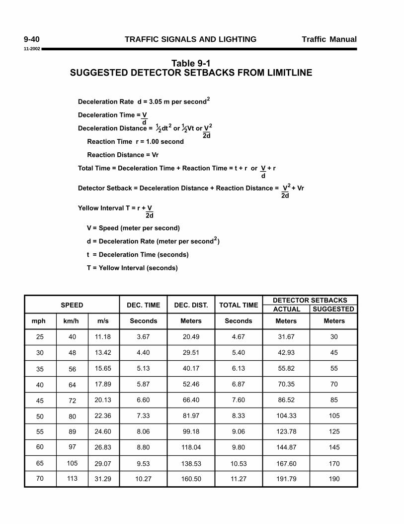
The longitudinal location (setback) of detectorsrelative to the limit line depends on the speed oftraffic and the type of detector operation desired.Suggested setbacks are shown in Table 9-1.
9-03.25 Pedestrian Detectors
Where required, pedestrian push buttons shouldbe located convenient to the corresponding crosswalkso as to encourage their use by both pedestrians andpeople in wheelchairs. Push buttons should belocated not more than 1.5 m from the crosswalk andshould be placed on signal poles if they are adjacentto the crosswalk area. Separate pedestrian push-button posts should be used when the signal polesare more than 1.5 m from the crosswalk.
9-03.26 Bicycle Detectors
Bicycle detectors may be required at traffic-actuated signal installations.
A Type D loop configuration shown on StandardPlan ES-5B is effective for detecting bicycles andsmall motorcycles and shall be installed at the bicycleloop detector locations. Loop detectors shall not beplaced within a pedestrian crosswalk or where itcould conflict with pedestrian traffic.
The loop detector logo shown on Standard PlanA24C may be used to show a bicyclist where to stopin a bike lane or traffic lane to be detected. The logoshould be applied to the pavement in the center of theType D loop.
See Figure 9-12 for suggested locations of bicycledetectors and the Standard Plans for typical bikelane pavement markings.
9-03.27 Signal Plan Schedules
The traffic signal plans for the installation of anew signal or the major modification of an existingsignal should include the following schedules:
TRAFFIC SIGNALS AND LIGHTINGTraffic Manual11-2002
9-31
1. Pole and Equipment Schedule.
A pole and equipment schedule shows thetypes of standards, mast arm lengths, typesand mounting for vehicle and pedestriansignal faces, and other equipment. SeeFigure 9-23 and the Standard Plans.
2. Conductors and Conduit Schedule.
A conductor and conduit schedule showsthe size of each conduit run, and the size,type and number of conductors or cables ineach conduit run. See Figure 9-24.
Dimensions of conductors and conduit and datafor determining conduit size are shown in Tables 9-8 and 9-9.
9-03.28 Preemption
At some signal locations, it is necessary topreempt the normal traffic signal operation by arailroad train, an emergency vehicle or bus/transitvehicles.
The order of priority for various types ofpreemption shall be:
1. Railroad
2. Emergency Vehicle
3. Bus/Transit Vehicles
9-03.29 Railroad Preemption
Railroad preemption results in a special trafficsignal operation depending on the relation of therailroad tracks to the intersection, the number ofphases in the traffic signal and other traffic conditions.Railroad preemption is normally controlled by therailroad grade crossing warning equipment.
Typical circumstances where railroad preemptionis required and the type of signal operation to beprovided during preemption are as follows:
1. Where a railroad grade crossing, providedwith grade crossing warning equipment, iswithin 60 m of a signalized intersection,preemption of the traffic signal should providethe following sequence of operation:
a. A yellow change interval and any requiredred clearance interval for any signal phasethat is green or yellow when preemptionis initiated and which will be red duringthe track clearance interval. The lengthof yellow change and red clearanceintervals shall not be altered bypreemption. Phases which are in thegreen interval when preemption isinitiated, and which will be green duringthe track clearance interval, shall remaingreen. Any pedestrian walk or clearanceinterval, in effect when preemption isinitiated, shall immediately be terminatedand all pedestrian signal faces shalldisplay steady DONT WALK orupraised HAND.
b. A track clearance interval for the signalphase or phases controlling the approachwhich crosses the railroad tracks. Thesignal indication for the clearance intervalmay be either green or flashing red.
c. A yellow change interval if green signalindications were provided during thetrack clearance interval.
d. Depending on traffic requirements andphasing of the traffic signal controller,the traffic signal may then do one of thefollowing:

TRAFFIC SIGNALS AND LIGHTING Traffic Manual11-2002
9-32
pedestrian clearance intervals in effectwhen preemption is initiated shall beimmediately terminated and all pedestriansignal faces shall display DONT WALKor upraised HAND.
b. All signal faces controlling trafficmovements parallel to the railroad trackswill display green or flashing yellowindications. All other vehicle signal faceswill display red indications; pedestriansignal faces will display DONT WALKor upraised HAND.
3. Where the railroad tracks run along aroadway of a signalized intersection andtrain speeds do not exceed 16 km/h, trainsmay be controlled by the vehicle signalindications. This type of train control requiresapproval from the railroad, the Public UtilitiesCommission and the Director ofTransportation.
4. Unusual or unique track or roadwayconfigurations may require other solutionsthan those described above.
9-03.30 Emergency Vehicle Preemption
Traffic signals on State highways may bepreempted by authorized emergency vehicles. Thepurpose of such preemption is to provide the right ofway to the emergency vehicle as soon as practical.The preemption may be controlled by one of thefollowing means:
1. By direct wire, modulated light or radio froma remote location such as a fire house; and
2. By modulated light or radio from anemergency vehicle.
(1) Go into flashing operation, withflashing red or flashing yellowindications for the approachesparallel to the railroad tracks andflashing red indications for all otherapproaches. Pedestrian signals shallbe extinguished. If flashing red isused for all approaches, an all-red orother clearance interval shall beprovided prior to returning to normaloperation.
(2) Revert to limited operation with thosesignal indications controlling throughand left turn approaches towards therailroad tracks displaying steady red.Permitted pedestrian signal phasesshall operate normally. Thisoperation shall be used only if thegrade crossing warning equipmentincludes gates.
e. The traffic signal shall return to normaloperation following release of preemptioncontrol.
2. Where the railroad tracks run within aroadway and train speeds exceed 16 km/h,preemption of the traffic signal should providethe following sequence of operation.
a. A yellow change interval and any requiredred clearance interval for all signal phasesthat are green or yellow when preemptionis initiated and which will be red duringthe preemption period. The length ofyellow change and red clearance intervalsshall not be altered by preemption.Phases which are in the green intervalwhen preemption is initiated and whichwill be green during the preemptionperiod, shall remain green. Any walk or

TRAFFIC SIGNALS AND LIGHTINGTraffic Manual11-2002
9-33
Emergency vehicle preemption should providethe following sequence of operation:
1. A yellow change interval and any requiredred clearance interval for any signal phasethat is green or yellow when preemption isinitiated and which will be red during thepreemption interval. The length of the yellowchange and red clearance intervals shall notbe altered by preemption. Phases which arein the green interval when preemption isinitiated and which will be green during thepreemption period shall remain green. Anypedestrian walk interval in effect whenpreemption is initiated shall be immediatelyterminated. The normal pedestrian clearanceinterval may be abbreviated.
2. An all-red intersection preemption displayshall not be used.
3. The traffic signal shall return to normaloperation upon termination of the demandfor preemption or the termination of theassured green interval.
At a traffic signal provided with both emergencyvehicle preemption and railroad preemption, therailroad preemption shall have priority. In the eventof a demand for an emergency vehicle preemptionduring the time that the intersection is operating onrailroad preemption, the railroad preemptionsequence shall continue unaffected until completion.In the event of a demand for railroad preemptionduring emergency vehicle preemption operation,railroad preemption shall immediately assume controlof the intersection.
When control of emergency vehicle preemptionis by means of a radio or modulated light source, thefollowing shall apply:
1. The transmitter shall be permanently mountedon the emergency vehicle or building andshall operate at a range sufficient to permit anormal yellow change interval and anyrequired clearance intervals to take placeprior to the arrival of the emergency vehicle.The normal pedestrian clearance intervalmay be abbreviated.
2. The preemption system may provide anindication (such as a special signal) to thedriver of an emergency vehicle thatpreemption of the traffic signal has beeneffected. If a special signal light is used, thecolor shall not be red, yellow, or green.
3. The system shall be designed to preventsimultaneous preemption by two or moreemergency vehicles on separate approachesto the intersection.
When performed by a local agency, theinstallation of emergency vehicle preemptionequipment shall be covered by an EncroachmentPermit issued by the District Director. The permitshall state the applicable requirements from thoselisted above and the following:
1. It should be understood that the permit forthe installation may be revoked or changedas deemed advisable or necessary byCaltrans.
2. The timing of the preemption equipment shallbe as approved in advance by Caltrans andshall not be changed without writtenpermission. The Permittee shall make anychanges in timing requested by Caltrans.
3. The Permittee shall assume all liability for theclaims which arise due to or because of thepermit.

TRAFFIC SIGNALS AND LIGHTING Traffic Manual11-2002
9-34
Normally emergency vehicle preemptionequipment is installed, operated, and maintained atno cost to the State. An exception is where theequipment is installed for use by vehicles of anotherState agency.
The State will maintain the preemption equipmentat the traffic signal when the signal is maintained bythe State. The costs of such maintenance shall be at100% local agency expense.
9-03.31 Bus/Transit Vehicle Priority
The requirements for bus/transit vehicle priorityinsofar as installation, encroachment permit,maintenance and funding are the same as statedabove for emergency vehicle preemption.
The equipment and operation requirements forbus/transit vehicle priority shall be similar to thoseabove for emergency vehicle priority. Someexceptions to these requirements are:
1. Equipment requirements for the transmitterare set forth in Section 25352 of the CaliforniaVehicle Code.
2. Any pedestrian interval in effect when priorityis initiated shall not have its timing affected.
3. Normally, bus/transit priority should notoccur more than once every other signalcycle.
9-03.32 Modification of Existing Signals
Where existing signals are to be modified, it isdesirable that the construction plans include a separateplan of the existing system as well as a plan showingthe modifications. It may also be necessary toinclude a tabulation on the plan showing suchappurtenances as backplates and special signal facesthat may be difficult to discern on a complicatedplan.
The design of any signal modification projectshould include adequate consideration for keepingthe existing signals in operation while the modificationwork is being done.
9-03.33 Signals on Poles Owned by Others
Traffic signal equipment may be attached topoles owned by utility companies or other agencieswhen it is desired to keep the number of poles at anintersection to a minimum. In such cases, it isnecessary to enter into an agreement with the ownerof the pole. The agreement should be written to holdthe owner of the pole free of liability relative tooperation of the traffic signal or damage to the poleand to make the State responsible for moving theequipment in the event the pole is removed orrelocated.
9-03.34 Additional Capacity at SignalizedIntersections
When the vehicular volume on a two-lane Statehighway is large enough to warrant traffic signals,usually there will be considerable congestion afterthe signals are installed unless the State highway iswidened to four lanes at the intersection. Sometimes,it is also necessary to widen the intersecting road.
Where possible, the State highway approachesand local road approaches should be widened totwo lanes for through traffic, for a minimum of 60 mfor traffic approaching the intersection and for aminimum of 100 m for traffic leaving the intersection.Additional widening for tapered sections should beprovided at the ends of the added lanes. It may benecessary to prohibit parking in these areas and/orto provide left turn lanes. See Section 9-02.4 forfinancing.

TRAFFIC SIGNALS AND LIGHTINGTraffic Manual11-2002
9-35
9-03.35 Temporary Signals for Haul Roads or One-Way Traffic Control in Construction Zones
1. General.
Temporary signals for traffic control at theintersection of a State highway and a haulroad, or to provide one-way traffic controlthrough a construction zone, may be eitherthe fixed or portable type. Such signals arenormally installed by a contractor and mayrequire an Encroachment Permit.
2. Requirements.
Each plan for temporary signals shouldinclude the equipment details as well as thefollowing operating requirements:
a. Temporary signals shall meet the designstandards described earlier in this section.
b. Signal faces, detectors and controlequipment are to be kept in goodoperating condition at all times.
c. When not in use, portable signals are tobe removed from the vicinity of thehighway and fixed signals are to be placedin flashing operation with yellowindications for the highway and redindications for the haul road.
d. Timing of the signals will be determinedby the Agency having jurisdiction.
e. A SIGNAL AHEAD (W41) sign (andflashing beacon, if required) is to beplaced on each approach of the highwayin advance of the signal.
f. Haul road signals shall be operated usingmanual control or vehicle detectors. Theoperation shall provide a green indicationto the haul road only if the contractor’sequipment is approaching the crossing.The haul road green interval shall notexceed 10 seconds and the highwaygreen interval shall not be less than 20seconds, unless specific permission isgiven in writing. A 3-second, minimum,yellow change interval, and any requiredred clearance interval, shall follow eachgreen interval.
g. One-way traffic control signals may utilizepretimed or traffic-actuated controllerunits, or may be manually controlled. A3-second, minimum, yellow changeinterval shall follow each green interval.An all-red clearance interval shall followeach yellow change interval. The all-redclearance interval shall permit a vehicleto travel the length of the one-way lanebefore a green indication is shown toopposing traffic.
h. Failure to comply with any of the aboveor other specified conditions will bejustification for revoking the permit.
3. Equipment Details.
Fixed temporary traffic signals shall bedesigned for 120-volt operation, whileportable temporary signals may be batteryoperated.
The vehicle signal faces shall be the standard3-section type with no less than two separatesignal faces for each approach, including thehaul road approaches.

TRAFFIC SIGNALS AND LIGHTING Traffic Manual11-2002
9-36
The signal faces shall be mounted a minimumof 3 m above the roadway and directed sothat the indications are readily seen by traffic.The signal faces for highway traffic shall beequipped with backplates.
For one-way lane control or where conditionsrequire sets of signals to be coordinated, thesets may be interconnected by cable or radioso that they are operated from a singlemanual or automatic control. The controlsystem shall be designed to prevent conflictinggreen indications.
9-03.36 Lane-Use Control Signals
Lane-use control signals are special overheadsignals having indications used to permit or prohibitthe use of specific lanes of a street or highway or toindicate the impending prohibition of use.
Lane-use control signals shall conform to therequirements in Part IV of the MUTCD.
9-03.37 Ramp Metering Signals
Traffic control signals may be installed on freewayentrance ramps to control the flow of traffic enteringthe freeway facility.
Ramp metering control signals shall conform tothe requirements in Part IV of the MUTCD andCaltrans Ramp Meter Design Guidelines.
9-03.38 Signals at Movable Bridges
Signals installed at movable bridges are a specialtype of highway traffic signal, the purpose of whichis to notify traffic to stop because of a road closurerather than alternately giving the right of way toconflicting traffic movements. They are operated incoordination with the opening and closing of themovable bridges. Unlike traffic control signals,movable bridge signals may be operated frequentlyor at extremely infrequent intervals depending uponwaterway traffic. Signals at movable bridges shallconform to the requirements in Part IV of theMUTCD.

TRAFFIC SIGNALS AND LIGHTINGTraffic Manual11-2002
9-37
Traffic Signal Operations 9-04
9-04.1 Introduction
The California Department of Transportation isresponsible for the operation of all State highwaytraffic signals, regardless of whether the signal ismaintained by the State or by others. State highwaytraffic signals shall include, but are not necessarilylimited to, all signals on a State highway and at rampconnections to local streets. Maintenance andoperation of highway traffic signals involving StateHighways by an agency other than the CaliforniaDepartment of Transportation shall require a jointlyapproved written agreement.
9-04.2 Review of Traffic Signal Operations
All State highway traffic signals should beperiodically reviewed for proper operation.
The traffic signal operation should be observedduring morning and evening peak traffic periods andduring off-peak periods. If an operating deficiencyis observed, the reason for the deficiency should bedetermined. If there is a malfunction, Maintenanceshould be notified, and after corrective work isdone, further surveillance should be conducted to besure no deficiency remains. If a need for a designchange is observed, an analysis should be made todetermine what improvement might be necessary toimprove the design.
Improvements to consider are:
1. Timing of:
a. Maximums or Force Offs
b. Gap Interval
c. Offsets
d. Cycle Length
2. Time-of-Day or Traffic Responsive Settings
3. Signal Phasing or Phase Sequence
4. Type of Operation
5. Coordination of Signals
6. Signs, Striping and/or Pavement Markings
7. Roadway Improvements
Initial timing of traffic signals and any subsequentchanges in timing shall be the responsibility of TrafficOperations. Timing records shall be kept and bereadily available to maintenance and traffic operationsstaff and other agencies, where appropriate.
Aids for timing are shown in Tables 9-2, 9-3, 9-4, 9-5, 9-6 and 9-7.
9-04.3 Signals at Interchanges
Signals at freeway interchanges require specialconsideration as to phasing and timing to minimizebackup of traffic onto the freeway lanes.
In addition, signals at diamond-type interchangesrequire phasing and timing to provide the necessaryturning movements from the cross street to and fromthe ramps, without a backup of traffic between theramps. Tables 9-3 and 9-4 are guides to be used todetermine the timing of traffic signals at diamondinterchanges. These tables should be used inconjunction with Table 9-2 to determine the timingof the splits and offsets for diamond interchangesignals.
The decision whether to use pretimed or traffic-actuated operation is dependent not only upon trafficconditions in the interchange area, but also upontraffic conditions along the cross street. For example,a coordinated traffic signal system along the crossstreet may require that the signals at the interchangebe coordinated with the cross street progression.
TRAFFIC SIGNALS AND LIGHTING Traffic Manual11-2002
9-38
9-04.4 Timing of Green Intervals
The proportion of green time, or split, allotted toeach phase or combination of phases during a signalcycle, should be as close as practicable to theproportion of critical lane traffic volumes on therespective approaches. In traffic-actuated operation,this proportioning is done automatically andcontinuously as a result of vehicle detector inputs tothe controller unit.
Factors that may modify this proportioning arethe time required for pedestrian intervals and therequirements of a coordinated system.
In the usual signal operation, predeterminedsplits can be selected by time-of-day or traffic-responsive equipment. In coordinated signal systems,the cycle length and the split can be varied bycommand from the system master controller.
9-04.5 Yellow Change Intervals
The purpose of the yellow signal indication is towarn traffic approaching the signal that the relatedgreen movement is ending or that a red indication willbe exhibited immediately thereafter and traffic willbe required to stop when the red signal is exhibited.
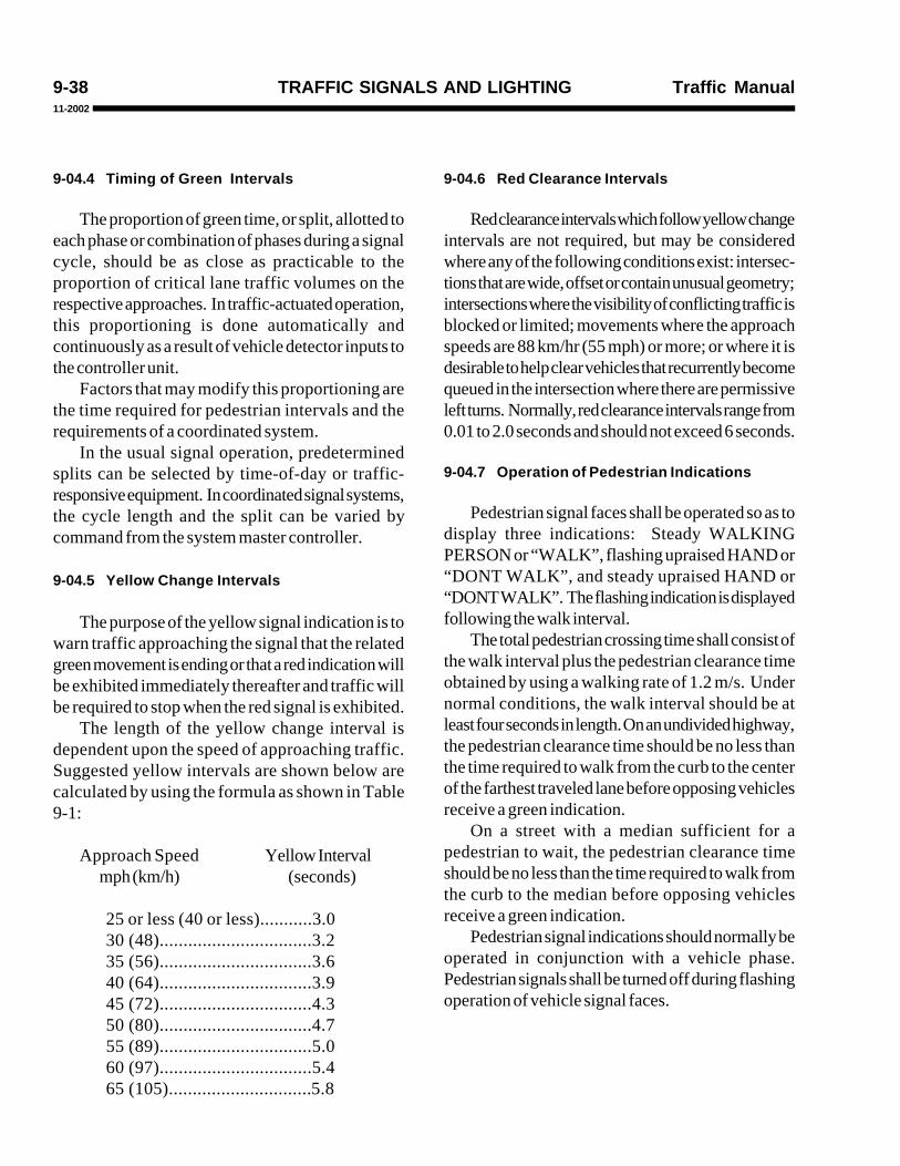
The length of the yellow change interval isdependent upon the speed of approaching traffic.Suggested yellow intervals are shown below arecalculated by using the formula as shown in Table9-1:
Approach Speed Yellow Intervalmph (km/h) (seconds)
25 or less (40 or less)...........3.030 (48)................................3.235 (56)................................3.640 (64)................................3.945 (72)................................4.350 (80)................................4.755 (89)................................5.060 (97)................................5.465 (105)..............................5.8
9-04.6 Red Clearance Intervals
Red clearance intervals which follow yellow changeintervals are not required, but may be consideredwhere any of the following conditions exist: intersec-tions that are wide, offset or contain unusual geometry;intersections where the visibility of conflicting traffic isblocked or limited; movements where the approachspeeds are 88 km/hr (55 mph) or more; or where it isdesirable to help clear vehicles that recurrently becomequeued in the intersection where there are permissiveleft turns. Normally, red clearance intervals range from0.01 to 2.0 seconds and should not exceed 6 seconds.
9-04.7 Operation of Pedestrian Indications
Pedestrian signal faces shall be operated so as todisplay three indications: Steady WALKINGPERSON or “WALK”, flashing upraised HAND or“DONT WALK”, and steady upraised HAND or“DONT WALK”. The flashing indication is displayedfollowing the walk interval.
The total pedestrian crossing time shall consist ofthe walk interval plus the pedestrian clearance timeobtained by using a walking rate of 1.2 m/s. Undernormal conditions, the walk interval should be atleast four seconds in length. On an undivided highway,the pedestrian clearance time should be no less thanthe time required to walk from the curb to the centerof the farthest traveled lane before opposing vehiclesreceive a green indication.
On a street with a median sufficient for apedestrian to wait, the pedestrian clearance timeshould be no less than the time required to walk fromthe curb to the median before opposing vehiclesreceive a green indication.
Pedestrian signal indications should normally beoperated in conjunction with a vehicle phase.Pedestrian signals shall be turned off during flashingoperation of vehicle signal faces.

TRAFFIC SIGNALS AND LIGHTINGTraffic Manual11-2002
9-39
9-04.8 Audible Pedestrian Signals
1. General.
Audible Pedestrian Signals may be installedat signalized intersection crosswalks. Thesedevices supplement visual WALK indicationsand are designed to aid visually impairedpedestrians. The installation of AudiblePedestrian Signals may be considered whenan engineering study and evaluation havebeen conducted and the following minimumconditions have been met:
a. The proposed intersection crosswalkmust be signalized.
b. The audible devices should beretrofittable to the existing traffic signalhardware.
c. The signalized intersection should beequipped with pedestrian push buttons.
d. The selected crosswalk must be suitablefor the installation of audible signals, interms of surrounding land use and trafficpatterns.
e. There must be a demonstrated need forthe audible signals in the form of a requestfrom an individual or group that woulduse the audible signal.
f. The individual or group requesting thedevice should agree to train the visuallyimpaired users of the audible signals.
It is recommended that the audible devicesselected emit a “Cuckoo” walk sound for acrosswalk in the North-South direction anda “Peep-Peep” walk sound for a crosswalkin the East-West direction.
2. Financing.
The cost of installing Audible PedestrianSignals shall be shared with the local agencyin the same manner as a traffic signal. SeeSection 9-02.4.
9-04.9 Continuity of Operation
Once a traffic signal at an intersection orpedestrian crossing has been energized, it shall notbe turned off unless arrangements have been madefor temporary control by traffic officers, temporarystop signs or an approved portable signal.
When a traffic signal at an intersection orpedestrian crossing is not to be in operation for aplanned, extended period of time, the signal facesshould be hooded, turned away from traffic orremoved.
Refer to the Highway Maintenance Manual forprocedures to provide traffic controls at signalizedintersections during planned or unplanned utilitycompany power outages.
9-04.10 Flashing Operation
Flashing operation may be used prior to placingthe signal in automatic stop-and-go operation orwhen required by seasonal traffic conditions. Duringflashing operation, red/yellow or all red indicationsmay be used.
Pretimed or semi-traffic-actuated traffic signalsmay be operated in a flashing mode at night. Flashingyellow operation for the major street in a coordinatedsignal system reduces control of vehicle speed. Ifsuch speed control is desired, properly spacedsignals should remain in automatic stop-and-gooperation.
Actuated signals at an isolated intersection shouldnever be operated in a flashing mode except duringemergencies, the operation of a conflict monitoringdevice, or during railroad preemption.
The emergency mode of operation for all trafficsignals shall be flashing operation.
TRAFFIC SIGNALS AND LIGHTING Traffic Manual11-2002
9-40
����������� � ��� � ����� �������������������
����� ���� ��� ��� ����� ��
���� �� ���� ��� ��� �
����� ���� ���� ���� ����� ��
���� ���� ���� ���� ����� ��
����� ���� ���� ���� ����� ��
����� ���� ���� ���� ����� ���
���� ���� ��� ��� ������ ���
����� ���� ����� ��� ���� ��
�
�
�
��
��
�
��
�
���� ��� �� !"� �� !"���#�$� ��#�$� ��#�$�
% � � �&���� � �&����& ���������
��
��
��
��
�
�
��
��
�'�
���� ��� ������ ����� ������ ��������
���� ����� ������ ����� ���� �������
� � ����� �������� � �������
������$�#( !���#���"�)�*&+,���'�$���� !"
������$�#( !��(���)�-
������$�#( !��(�#�!���)�����"#��� $����-#� $�-
���������#( !��(����$�)�&++���� !"
���������#( !��(�#�!���)�-$
� #����(���)�������$�#( !��(���.�����#( !��(���)�#�.�$�� $��-�.�$
��#��# $��#�����)�������$�#( !��(�#�!���.�����#( !��(�#�!���)�������.�-$
/��� 0��!#�$1�����)�$�.�-
���� - ) '��"�2��#�$�'�$���� !"3
���� " ) ������$�#( !���#��2��#�$�'�$���� !"��3
���� # ) ������$�#( !��(���2��� !"�3
���� � ) /��� 0��!#�$1���2��� !"�3
44
4
4
"
4
4
4"
4"-4
4"
"
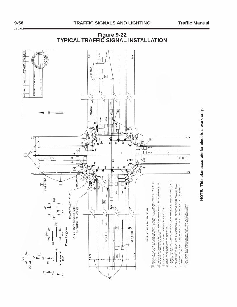
Traffic Manual9-58 TRAFFIC SIGNALS AND LIGHTING
Figure 9-22TYPICAL TRAFFIC SIGNAL INSTALLATION
11-2002
NO
TE:
This
pla
n ac
cura
te fo
r el
ectr
ical
wor
k on
ly.
Not
to S
cale
INS
TRU
CTI
ON
S T
O D
ES
ING
ER
INS
TALL
ATIO
N O
F S
ER
VIC
E E
QU
IPM
EN
T, C
ON
DU
ITS
, PU
LL B
OX
ES
, AN
D S
ER
VIC
E R
ISE
RS
HA
LL S
ATIS
FY T
HE
RE
QU
IRE
ME
NTS
OF
THE
SE
RV
ING
UTI
LITY
.
DIS
TAN
CE
FR
OM
DE
TEC
TOR
TO
LIM
IT L
INE
TO
BE
DE
TER
MIN
ED
BY
DE
SIG
NE
R A
ND
AS
IND
ICAT
ED
IN T
HE
DE
SIG
N G
UID
E.
NA
ME
OF
SE
RV
ING
UTI
LITY
TO
BE
IND
ICAT
ED
BY
DE
SIG
NE
R.
WID
TH T
O B
E IN
DIC
ATE
D B
Y D
ES
IGN
ER
.
SIG
NA
L A
ND
LIG
HTI
NG
SE
RV
ICE
WIR
ING
DIA
GR
AM
SH
ALL
SAT
ISFY
TH
E S
ER
VIN
G U
TILI
TYR
EQ
UIR
EM
EN
TS.
CE
NTE
R L
INE
S, L
AN
E L
INE
S A
ND
STA
TIO
NS
SH
ALL
BE
SH
OW
N O
IN T
HE
SIG
NA
L P
LAN
.
A C
OM
PLE
TE S
IGN
ING
AN
D P
AVE
ME
NT
DE
LIN
EAT
ION
PLA
N S
HA
LL B
E P
RO
VID
ED
AS
SE
PAR
ATE
SH
EE
T
SE
E T
RA
FFIC
MA
NU
AL
SE
CTI
ON
9-0
3, "
TRA
FFIC
SIG
NA
L D
ES
IGN
",FO
R F
UR
THE
R IN
FOR
MAT
ION
ON
DE
SIG
N A
ND
RE
FER
EN
CE
S.
1 2 3 4 8.7.6.5.
Phas
e Di
agra
m
Ø4P
Ø4
Ø8
Ø8P
OR
Ø1
Ø6
Ø6P
Ø5
Ø2
Ø2P
Ø5
Ø1
Ø6P
Ø2
Ø6
Ø2P

TRAFFIC SIGNALS AND LIGHTINGTraffic Manual11-2002
9-61
9-05.1 Introduction
Typical applications for flashing beacons includethe following:
1. Signal Ahead
2. Stop Signs
3. Speed Limit Signs
4. Other Warning and Regulatory Signs
5. Schools
6. Fire Stations
7. Intersection Control
8. Freeway Bus Stops
9. At Intersections Where a More VisibleWarning is Desired
A flashing beacon is one or more traffic signalsections with a flashing indication in each section.Because the effectiveness of flashing beacons hasnot been consistent from one location to another, thedecision whether or not to install a flashing beaconshould not be based solely upon the guidelines listedin this section.
Flashing beacons to be installed on a Statehighway shall conform to the following requirements:
1. Lenses should be 300 mm in diameter, exceptthat lenses for flashing beacons at bus stops,stop sign flashing beacons, speed limit signflashing beacons and beacons used inconnection with ramp metering may be 200mm in diameter.
2. A dimming device shall be used to reduce the
brilliance of yellow flashing beacons duringnighttime operation.
3. Two-section flashing yellow beacons maybe connected to flash alternately orsimultaneously.
9-05.2 Signal Ahead Flashing Beacons
Yellow flashing beacons may be used withSIGNAL AHEAD (W41) signs in advance of:
1. An isolated traffic signal on either aconventional highway or on an expresswayin a rural area.
2. The first traffic signal approaching an urbanarea.
3. Any traffic signal with limited approach visibility,or where approach speeds exceed 80 km/h(50 mph).
9-05.3 Design
On divided highways where the median is 2.5 mwide, or greater, the installation may consist of:
1. Two Type 1 standards, each with a W41sign and a 300 mm signal face, with onestandard located in the median and the otheroff of the right shoulder; or
2. A Type 9 cantilever flashing beaconinstallation with a W41 or W41A sign andtwo 300 mm signal faces as shown in theStandard Plans.
The above installation designs may result innoncompliance with the Highway Design Manualmandatory standards for horizontal clearance andshoulder width, and the advisory design standard for
Flashing Beacons 9-05

TRAFFIC SIGNALS AND LIGHTING Traffic Manual11-2002
9-62
clear recovery zones. If such nonstandard featurescannot be avoided, the designer must obtain approvalin accordance with Topic 82 of the Highway DesignManual and the current instructions pertaining toexceptions from mandatory and advisory designstandards.
On undivided highways or on highways wherethe median is less than 2.5 m wide, the installationmay consist of a single standard located off of theright shoulder as described for use on dividedhighways, or it may be a Type 9 cantilever flashingbeacon installation.
9-05.4 Financing
The cost of installing a Signal Ahead FlashingBeacon is normally included in the traffic signalproject and the cost shared with the local agency.See Section 9-02.6.
9-05.5 Warning or Regulatory Sign FlashingBeacons
Flashing beacon shall be used only to supplementan appropriate warning or regulatory sign or marker.
Typical applications include:
1. Obstructions in or immediately adjacent tothe roadway.
2. Supplemental to advance warning signs.
3. At mid-block crosswalks.
4. At intersections where a warning isappropriate.
The beacon should be operated only duringthose hours when the necessity for the warning orregulation exists.
9-05.6 Financing
The cost of installing a Warning or RegulatorySign Flashing Beacon on a State highway shall be at100% State expense.
9-05.7 Flashing Beacons at School Crosswalks
Flashing beacons at school crosswalks may beinstalled on State highways in accordance withSections 21372 and 21373 of the California VehicleCode. See Chapter 10 of this Manual for additionalguidelines and also Section 9-02.6, Case I.
9-05.8 Speed Limit Sign Flashing Beacons
A Speed Limit Sign Flashing Beacon may beinstalled on a State highway for use in connectionwith a fixed or variable speed limit sign. The size andlocation of the circular yellow lenses are describedin the MUTCD. When a Speed Limit Sign FlashingBeacon is installed at the request of a local agency,or installed by the local agency under a encroachmentpermit, the costs of installing and maintaining thebeacon should be at 100% local agency expense.
9-05.9 Intersection Control Flashing Beacons
An Intersection Control Flashing Beacon consistsof one or more signal sections, with a flashing circularyellow or circular red indication in each face.Application of Intersection Control Flashing Beaconsshall be limited to:
1. Yellow indications on one route (normallythe major roadway) and red indications forthe remaining approaches; or
2. Red indications for all approaches.
TRAFFIC SIGNALS AND LIGHTINGTraffic Manual11-2002
9-63
New installations of overhead intersection controlflashing beacons shall consist of red indications foreach approach.
A stop sign shall be used on each approach witha flashing red indication.
Basic intersection lighting should be installed atintersections where an Intersection Control FlashingBeacon is to be installed.
9-05.10 Financing
The cost of installing an Intersection ControlFlashing Beacon and intersection lighting shall beshared with the local agency in the same manner asa traffic signal. See Section 9-02.6.
9-05.11 Flashing Beacons for Fire Stations
Flashing beacons at fire station driveways or atintersections immediately adjacent to a fire stationmay be installed on State highways. The flashingbeacon shall be used only to supplement anappropriate warning or regulatory sign. The flashingbeacon shall be actuated from a non-illuminatedcondition by a switch at the fire station.
9-05.12 Financing
The costs of installing and maintaining the flashingbeacon for the fire station shall be at 100% localagency or fire department expense.
9-05.13 Stop Sign Flashing Beacons
A Stop Sign Flashing Beacon consists of one ortwo signal sections with a flashing circular redindication in each section. The bottom of the housingof a Stop Sign Flashing Beacon shall be not less than305 mm nor more than 610 mm above the top of thestop sign.
9-05.14 Financing
The cost of installing a Stop Sign Beacon shall beshared with the local agency in the same manner asa traffic signal. See Section 9-02.6.
9-05.15 Flashing Beacons at Bus Stops on FreewayInterchanges
At locations of approved bus stops withininterchange areas, a flashing beacon may be providednear the top of a lighting standard to provide a flagstop.
9-05.16 Design and Operations
The following design and operationalrequirements shall be met:
1. A push button shall be provided on thelighting standard with a sign explaining thepurpose and operation. The sign shall statethat if no bus has arrived within 15 minutes(or other time) after the button has beenactuated it will be necessary to actuate itagain.
2. The flashing beacon shall consist of an 200mm, signal section with an uncolored orwhite lens mounted on the lighting standardin such a position that it can be seen by anapproaching bus driver on the freeway.
3. The operation of the control shall be suchthat the flashing beacon will operate for 15minutes after the button has been actuatedand then go out.
9-05.17 Financing
The costs of installing and maintaining FlashingBeacons at Bus Stops on Freeway Interchangesshall be at 100% State expense.
TRAFFIC SIGNALS AND LIGHTING Traffic Manual11-2002
9-74
9-11.4 Slip Bases
Slip bases shall be used under Types 30 and 31standards and under Type 15 standards on freeways,expressways and conventional highways wherespeeds are in excess of 64 km/h. Exceptions to thispolicy are that slip bases are not used under lightingstandards upon which signals are mounted or underlighting standards located:
a. On or behind structures, retaining walls orbarrier railing;
b. In sidewalk areas;
c. Behind guardrail;
d. More than 9 m from traveled way; or
e. Where pedestrians would be close enoughto be endangered by a pole knockdown.
Luminaires 9-12
9-12.1 General
Normally, the luminaire for a new installation ofsafety lighting on State highways is a full-cutoff typeusing a high pressure sodium lamp.
9-12.2 Roadway Luminaires
On freeways, 200-watt lamps shall be used with9.14 m mounting heights and 310-watt lamps shallbe used with 12.19 m mounting heights. Onconventional highways and at the intersections offreeway ramps with surface streets, 150-watt lampsshall be used with 9.14 m mounting heights.
Utility owned semi-cutoff type luminaires shouldbe provided with glare shields in rural areas.
9-12.3 Soffit Luminaires
Soffit luminaires are special fixtures either sus-pended from or flush-mounted into structures toilluminate the roadway under the structure. Theyshall be used with 70 or 100 watt high-pressuresodium lamps, depending upon lighting requirements.Normally, the fixtures should not be located over thetraveled way on freeways.
9-12.4 Wall Luminaires
Wall luminaires are fixtures designed to be sur-face mounted on vertical surfaces. However, asimple right angle bracket permits mounting themfrom a horizontal surface such as the bottom slab ofa box girder. They are used with the same lamps assoffit luminaires.
TRAFFIC SIGNALS AND LIGHTING Traffic Manual11-2002
9-80
9-13.6 Conduit on Structures
Conduits should be run either parallel to or atright angles to the structure girders. A variation of±15 degrees is acceptable.
Except for sidewalk joints, a conduit expansionfitting should be installed at each structure joint,hinge or abutment where a longitudinal movement of12 mm or greater may occur. Where a lateralmovement of 6 mm or greater may occur, anexpansion-deflection fitting should be installed.Details for placement of expansion fittings andexpansion-deflection fittings are shown in theStandard Plans.
9-13.7 Pull Boxes
Pull boxes should be installed to limit the lengthof conductor pull, to provide a point where conduitscan be branched and/or conductors can be splicedand to simplify access to standards, poles andcabinets.
9-13.8 Installation of Pull Boxes
Pull Boxes should be installed:
1. At 60 m, or less, spacing in conduit runs;
2. At locations where conduits branch;
3. Adjacent to the foundation for each signalstandard, lighting standard, illuminated sign,controller cabinet or service cabinet; and
4. At the toe of slope or at the hinge point whenplaced on a slope.
Pull boxes should not be installed in the traveledway if it can be avoided. When it is necessary to
install them in the traveled way, the box, cover andfoundation should be capable of supporting heavywheel loading.
9-13.9 Pull Box Size
The minimum size of pull boxes for variousapplications should be as follows:
1. Signal or Lighting Conduits No. 52. Adjacent to Signal
or Lighting Standards No. 53. Adjacent to
Controller Cabinet No. 64. Adjacent to
Service Cabinet No. 55. Detector Termination No. 56. With 4, or more, Conduits No. 67. Telephone Conduits No. 5
Pull boxes with transformers should be providedwith extensions.
9-13.10 Wiring
The dimensions of conductors normally used intraffic signal and highway lighting circuits are shownin Table 9-9. The values shown in the table may beused to calculate conduit fill.
9-13.11 Voltage Drop
The conductors between the service point andthe load (lamps, ballasts, controller cabinets, etc.)should be sized to limit the voltage drop to lessthan 5%.
The resistance (ohms per 1,000 m) of conductorscommonly used in traffic signal and highway lightingcircuits is shown in Table 9-9. The values shown arebased on an ambient temperature of 75O C.

TRAFFIC SIGNALS AND LIGHTINGTraffic Manual11-2002
9-81
Voltage drop can be calculated using:
Volts Drop = 2ILR
Where: I = CurrentL = Length of ConductorR = Resistance of Conductor
(1,000 m)
If the voltage drop is known, the followingformula can be used to determine the minimumconductor size:
R = Volts Drop ÷ 2IL
Example: The allowable voltage drop for a 380m run feeding a 6.5 ampere load is 12 volts.
R = 12 ÷ (2) (6.5) (.38) = 2.43
From Table 9-9, the minimum wire size isNo. 6.
9-13.12 Circuit Voltages
Traffic signal and flashing beacon controlequipment normally is designed to operate on a 120-volt AC circuit.
A 120-volt or 240-volt circuit is normally usedfor highway lighting circuits. For very large lightingcircuits, a 480-volt circuit may be required.