department of the army technical manual direct … · tm 9-1400-461-35 technical manual...
TRANSCRIPT

TM 9-1400-461-35
D E P A R T M E N T O F T H E A R M Y T E C H N I C A L M A N U A L
DIRECT SUPPORT, GENERAL SUPPORTAND
DEPOT MAINTENANCE MANUAL:GUIDED MISSILE LAUNCHER HELICOPTER
ARMAMENT SUBSYSTEM M22(USED ON UH-1B HELICOPTER)
This copy is a reprint which includes currentpages from Changes 1 through 6.
H E A D Q U A R T E R S , D E P A R T M E N T O F T H E A R M Y
F E B R U A R Y 1 9 6 5

TM 9-1400-461-35
TECHNICAL MANUAL HEADQUARTERS,DEPARTMENT OF THE ARMY
No. 9-1400-461-35 WASHINGTON, D.C., 1 February 1965
GUIDED MISSILE LAUNCHER HELICOPTER ARMAMENTSUBSYSTEM M22
(USED ON UH-1B HELICOPTER)
Paragraphs PagesCHAPTER 1. INTRODUCTION .................................................................................... 1-4 3
CHAPTER 2. THEORY OF OPERATIONSection I. General................................................................................................... 5-6 5
II. Guidance control unit .............................................................................. 7-19 5III. Missile selection box and control stick.................................................... . 20-21 18
CHAPTER 3. INSPECTION.......................................................................................... 22-24 23
CHAPTER 4. TROUBLESHOOTING............................................................................ 25-32 25
CHAPTER 5. CORRECTIVE MAINTENANCE............................................................. . 33-39 39
CHAPTER 6. AMMUNITIONSection I. General................................................................................................... 40-42 53
II. Inspection ............................................................................................... 43-44 53III. Electrical testing...................................................................................... 46-50 57
CHAPTER 7. SHIPMENT, STORAGE, STATIC FIRING, AND DETONATIONSection I. Shipment and storage ............................................................................. 51-53 63
II. Static firing and detonation...................................................................... 54-57 63
APPENDIX REFERENCES ....................................................................................... 93
INDEX .......................................................................................................................... 95
1
}

TM 9-1400-461-35
Figure 1. Helicopter guided missile launcher armament subsystem M22.
2

TM 9-1400-461-35
CHAPTER 1
INTRODUCTION
1. Scopea. This technical manual contains instructions and
procedures for direct support, general support, anddepot maintenance of the guided-missile-launcherhelicopter-armament subsystem M22 (fig. 1). Theseinstructions contain information on maintenance that isbeyond the scope of the tools, equipment, or suppliesnormally available to using organizations.
b. Information in this manual is to be used inconjunction with, and is supplementary to information inthe operator's (TM 9-1520-211-10) and organizational(TM 9-1400-461-20) maintenance manuals. It may benecessary to refer to the operator's or organizationalmaintenance manual in order to obtain completeprocedures.
c. This manual contains theory of operation,troubleshooting procedures, and maintenanceoperations peculiar to support and depot maintenance.The instructions in this manual are intended formaintenance personnel who have been especiallytrained to maintain the M22 subsystem. The study anduse of the information and maintenance guidelines inthis manual will enable maintenance crews to performtheir assigned duties and missions with maximumefficiency and safety.
d. The appendix contains a list of currentreferences, including supply and technical manuals,forms, and other available publications applicable to theM22 armament subsystem.
e. This manual reflects the most recent technicalinformation available. When additional or changedinformation affecting maintenance of the M22 armamentsubsystem becomes available, official changes to thismanual will be printed.
2. Errors, Omissions, and CorrectionsThe direct reporting of errors, omissions, and
recommendations for improving this equipment manualby the individual user, is authorized and encouraged.DA Form 2028 will be used for reporting theseimprovements. This form may be completed usingpencil, pen, or typewriter. DA Forms 2028 will becompleted by the individual using the manual andforwarded to: Commanding General, U. S. ArmyMissile Command, ATTN: AMSMI-SMPT, RedstoneArsenal, Alabama 35809.
3. Maintenance Allocation and PartsMaintenance responsibilities prescribed in this
manual will apply as reflected in the maintenanceallocation chart (TM 9-1400-461-20) and as reflected bythe allocation of repair parts and tools listed in TM 9-1400-461-35P.
4. Description and DataRefer to TM 9-1400-461-20 for the description
and data applicable to the M22 armament subsystem.
3

C1, TM 9-1400-461-35
CHAPTER 2THEORY OF OPERATION
Section I. GENERAL
5. System TheoryThe overall system theory of the M22
subsystem is covered in TM 9-1400-461-20.
6. Detailed Operational TheoryThis chapter provides direct support, general
support,
and depot maintenance personnel with detailedoperational theory to the component level. The theoryof each major component is covered in separatesections in this chapter.
Section II. GUIDANCE CONTROL UNIT
7. GeneralThis section covers the operational theory of the
guidance control unit (figs. 2 and 3). Operational theoryof the signal generator module (fig. 3) is the only theoryrequired as the remainder of the guidance control unit(fig. 2) contains only switches which connect straight linecircuits.
8. Signal Generator Operational TheorySignal generator operational theory will be
covered by explaining the normal operational sequencesof the unit with the control stick in the neutral position.Refer to figure 4 for block diagram of signal generatormodule.
9. Regulated Supply Voltage (fig. 5)Input battery voltage between 23 and 30 vdc is
applied between pins 6 (negative) and 7 (positive) whenthe firing sequence is initiated. A regulating bridgenetwork is connected across the inputs. This bridge iscomposed of two positive temperature coefficient zenerdiodes (CR1 and CR8) connected in series with sixnegative temperature coefficient diodes (CR2 throughCR7). This configuration provides operationalstabilization during temperatures between minus 30degrees centigrade and positive 50 degrees centigrade.Bias voltage for Q1 base is taken between R1 and CR1.This bias voltage varies in accordance with batterysupply
Apparatus List for the Guidance Control Unit, Figure 2
Referencedesignator Description Part No.
C1-C4 CAPACITOR, FIXED: 160v, 100,000 uuf (± 10%) 10172517DS1-DS4 LAMP, INCANDESCENT: 28v, 0.04 amp MS 25237-327J1 CONNECTOR, RECEPTACLE, ELECTRICAL: 10172485
2 male contactsJ2 CONNECTOR, RECEPTACLE, ELECTRICAL: 10022462
16 female contactsJ1031 CONNECTOR, RECEPTACLE, ELECTRICAL: 10172490
19 male contactsJ1036 CONNECTOR, BULKHEAD, ELECTRICAL: 10172767
7 male contactsK1 RELAY, ARMATURE 10172528K2 RELAY, ARMATURE 10172527K3 RELAY, ARMATURE 10172528K4 RELAY, ARMATURE 10172524K5, K6 RELAY, ARMATURE 10172528P1 CONNECTOR, PLUG, ELECTRICAL: 16 male contacts 10172658S1 SWITCH, ROTARY: 6 circuits, 6 positions 10172748V VOLTMETER 10021155
5

C1, TM 9-1400-461-35
Apparatus List for the Signal Generator Module, Figure 3
Referencedesignator Description Part No.
C1, C2 CAPACITOR, FIXED, TANTALUM: 16v, 150 uf, (± 10%) 10172693C3 CAPACITOR, FIXED, TANTALUM: 35v, 6.8 uf (± 10%) 10172694C4-C7 CAPACITOR, FIXED, TANTALUM: 16v, 100 uf (± 10%o) 10172695C8, C9 CAPACITOR, FIXED, MYLAR: 250v, 4,700 uuf 10172696CR1 SEMICONDUCTOR, DEVICE, DIODE: Type 108Z4 10172690CR2-CR7 SEMICONDUCTOR, DEVICE, DIODE: Type SG22 10172691CR8 SEMICONDUCTOR, DEVICE, DIODE: Type 108Z4 10172690CR9 SEMICONDUCTOR, DEVICE, DIODE: Type 12P2 10172689CR10 SEMICONDUCTOR, DEVICE, DIODE: Type 1N64 1N64CR11 SEMICONDUCTOR, DEVICE, DIODE: Type Z2A47 1N3825ACR12, CR13 SEMICONDUCTOR, DEVICE, DIODE: Type 19P2 10172687CR14, CR15 SEMICONDUCTOR, DEVICE, DIODE: Type 13P2 10021837CR16 SEMICONDUCTOR, DEVICE, DIODE: Type Z2A68 10172686CR17 SEMICONDUCTOR, DEVICE, DIODE: Type Z2A47 1N3825ACR18 SEMICONDUCTOR, DEVICE, DIODE: Type Z2A68 10172686CR19, CR20 SEMICONDUCTOR, DEVICE, DIODE: Type 19P2 10172687CR21 SEMICONDUCTOR, DEVICE, DIODE: Type Z2A47 1N3825ACR22 SEMICONDUCTOR, DEVICE, DIODE: Type Z2A68 10172686CR23, CR24 SEMICONDUCTOR, DEVICE, DIODE: Type Z2A47 1N3825AQ1 TRANSISTOR: OC-28 10172678Q2 TRANSISTOR: OC-47 10172632Q3 TRANSISTOR: 2N1566 10172680Q4 TRANSISTOR: OC-47 10172632Q5 TRANSISTOR: 2N493 10172681Q6 TRANSISTOR: OC-47 10172632Q7 TRANSISTOR: 2N1310 10172682Q8 TRANSISTOR: OC-77 10172683Q9 TRANSISTOR: 2N1310 10172682Q10 TRANSISTOR: OC-77 10172683Q11 TRANSISTOR: 2N1566 10172680Q12 TRANSISTOR: OC-141 10172684Q13, Q14 TRANSISTOR: OC-47 10172632Q15 TRANSISTOR: 2N1566 10172680Q16, Q19 TRANSISTOR: OC-47 10172632Q20, 22 TRANSISTOR: OC-141 10172684Q23 TRANSISTOR: OC-72 10121287Q24 TRANSISTOR: OC-141 10172684Q25 TRANSISTOR: OC-72 10121287R1 RESISTOR, FIXED: 1/2w, 220 ohms (±5%) 10172649R2 RESISTOR, VARIABLE: linear precision, 1w, 2,000 ohms 10172697
(± 05%, Z .23% linearity)R4 RESISTOR, FIXED: 1/4w, 1,000 ohms (± 5%) 10172704R5 RESISTOR, VARIABLE: 1/2w, 100,000 ohms 10172700R8 RESISTOR, FIXED: 1/4w, 82,000 ohms (± 5%) 10172725R9 RESISTOR, FIXED: 1/4w, 9,100 ohms (± 5%) 10172717R11 RESISTOR, FIXED: 1/2w, 10,000 ohms (± 5%) 10172718R12 RESISTOR, FIXED: 1/4w, 6,800 ohms (± 5%) 10172715R13 RESISTOR, FIXED: 1/4w, 12,000 ohms (± 5%) 10172720R14 RESISTOR, FIXED: 1/4w, 18,000 ohms (± 5%) 10172722R15, R16 RESISTOR, VARIABLE: wire wound element, 1 sec, 1w, 10172699
50,000 ohms (± 5%)R18 RESISTOR, FIXED: 1/4w, 6,200 ohms (± 5%) 10172714R19 RESISTOR, FIXED: 1/4w, 200 ohms (± 51%) 10172701R21 RESISTOR, FIXED: 1/4w, 2,200 ohms (± 5%) 10172708R22 RESISTOR, FIXED: 1/4w, 15,000 ohms (± 1%) 10172721R23 RESISTOR, FIXED: 1/4w, 20,000 ohms (± 5%) 10172723R24 RESISTOR, VARIABLE: wire wound element, 1 sec, 1w, 10172698
10,000 ohms (± 5%)
6

TM 9-1400-461-35
Figure 2. Guidance control unit, schematic diagram.
7

C1, TM 9-1400-461-35
Figure 3. Signal generator module, schematic diagram.
9

C1, TM 9-1400-461-35
Apparatus List for the Signal Generator Module, Figure 3— Cont’d
Referencedesignator Description Part No.
R25 RESISTOR, FIXED: 1/4w, 68,000 ohms (± 5%) 10172724R26 RESISTOR, FIXED: 1/4w, 5,600 ohms (± 5%) 10172713R27 RESISTOR, FIXED: 1/4w, 10,000 ohms (± 5%) 10172718R28 RESISTOR, FIXED: 1/4w, 750,000 ohms (± 5%) 10172688R29 RESISTOR, FIXED: 1/4w, 20,000 ohms (± 5%) 10172723R31 RESISTOR, FIXED: 1/2w, 1,200 ohms (± 5%) 10172706R32 RESISTOR, FIXED: 1/4w, 11,000 ohms (± 5%) 10172719R33 THERMISTOR: Type A, 5,000 ohms (± 5%) 10172692R34 RESISTOR, FIXED: 1/2w, 1,000 ohms (± 5%) 10172648R35 RESISTOR, FIXED: 1/4w, 6,800 ohms (± 5%) 10172715R36 RESISTOR, FIXED: 1/4w, 5,600 ohms (± 5%) 10172713R37 RESISTOR, FIXED: 1/2w, 1,000 ohms (± 5%) 10172648R38 RESISTOR, FIXED: 1/4w, 8,200 ohms (± 5%) 10172716R39 RESISTOR, FIXED: 1/4w, 5,600 ohms (± 5%) 10172713R41 RESISTOR, FIXED: 1/4w, 1,000 ohms (± 5%) 10172704R42 RESISTOR, FIXED: 1/4w, 4,300 ohms (± 5%) 10172711R43 RESISTOR, FIXED: 1/4w, 3,300 ohms (± 5%) 10172710R44 RESISTOR, FIXED: 1/4w, 20,000 ohms (± 5%) 10172723R45 RESISTOR, VARIABLE: wire wound element, 1 sec, 1w, 10172698
10,000 ohms (± 5%)R46 RESISTOR, FIXED: 1/4w, 18,000 ohms (± 5%) 10172724R47 RESISTOR, FIXED: 1/4w, 5,600 ohms (± 5%) 10172713R48 RESISTOR, FIXED: 1/4w, 10,000 ohms (± 5%) 10172718R49 RESISTOR, FIXED: 1/4w, 750,000 ohms (± 5%) 10172688R51 THERMISTOR: Type A, 5,000 ohms (± 5%) 10172692R52 RESISTOR, FIXED: 1/4w, 11,000 ohms (± 5%) 10172719R53 RESISTOR, FIXED: 1/2w, 1,000 ohms (± 5%) 10172648R54 RESISTOR, FIXED: 1/4w, 20,000 ohms (+ 5%) 10172723R55 RESISTOR, FIXED: 1/2w, 1,200 ohms (± 5%) 10172706R56 RESISTOR, FIXED: 1/4w, 9,100 ohms (± 5%) 10172717R57, R58 RESISTOR, FIXED: 1/4w, 5,(00 ohms (± 5%) 10172713R59 RESISTOR, FIXED: 1/4w, 3,300 ohms (± 5%) 10172710R61, R62 RESISTOR, FIXED: 1/4w, 2,700 ohms (± 5%) 10172709R63 RESISTOR, FIXED: 1/4w, 10,000 ohms (± 5%) 10172718R64 RESISTOR, FIXED: 1/4w, 1,000 ohms (± 5%) 10172704R65 RESISTOR, FIXED: 1/4w, 510 ohms (± 5%) 10172703R66 RESISTOR, FIXED: 1/4w, 47,000 ohms (± 5%) 10172707R67 RESISTOR, FIXED: 1/4w, 1,000 ohms (± 5%) 10172704R68 RESISTOR, FIXED: 1-4w, 510 ohms (± 5%) 10172703R69 RESISTOR, FIXED: 1-4w, 47,000 ohms (± 5%) 10172707R71, R72 RESISTOR, FIXED: 1/4w, 2,700 ohms (± 5%) 10172709R73 RESISTOR, FIXED: 1/4w, 10,000 ohms (± 5%) 10172718R74 RESISTOR, FIXED: 1/4w, 3,300 ohms (± 5%) 10172710R75 RESISTOR, FIXED: 1/4w, 10,000 ohms (± 5%) 10172718R76 RESISTOR, FIXED: 1/4w, 4,700 ohms (± 5%) 10172712R77 RESISTOR, FIXED: 1/4w, 4,300 ohms (± 5%) 10172711R78 RESISTOR, FIXED: 1/4w, 1,000 ohms (+ 5%) 10172704R79 RESISTOR, FIXED: 1/4w, 4,300 ohms (± 5%) 10172711R81 RESISTOR, FIXED: 1/4w, 20,000 ohms (+ 5%) 10172723R82 RESISTOR, FIXED: 1/4w, 4,700 ohms (± 5%) 10172712R83 RESISTOR, FIXED: 1/4w, 4,300 ohms (± 5%) 10172711R84 RESISTOR, FIXED: 1/4w, 1,000 ohms (± 5%) 10172704R85 RESISTOR, FIXED: 1/4w, 20,000 ohms (± 5%) 10172723R86 RESISTOR, FIXED: 1/4w, 4,300 ohms (± 5%) 10172711
11

TM 9-1400-461-35
Figure 4. Signal generator module block diagram.
change. Each variation of Q1 base bias changes basecollector current, producing variations in
Figure 5. Regulated supply voltage, schematicdiagram.
emitter-collector impedance. Changing emitter-collectorimpedance changes the voltage dropped, therebymaintaining a 21 ±.05 vdc output with an input between23 and 30 vdc. A regulated 11 vdc is also tappedbetween CR5 and CR6.
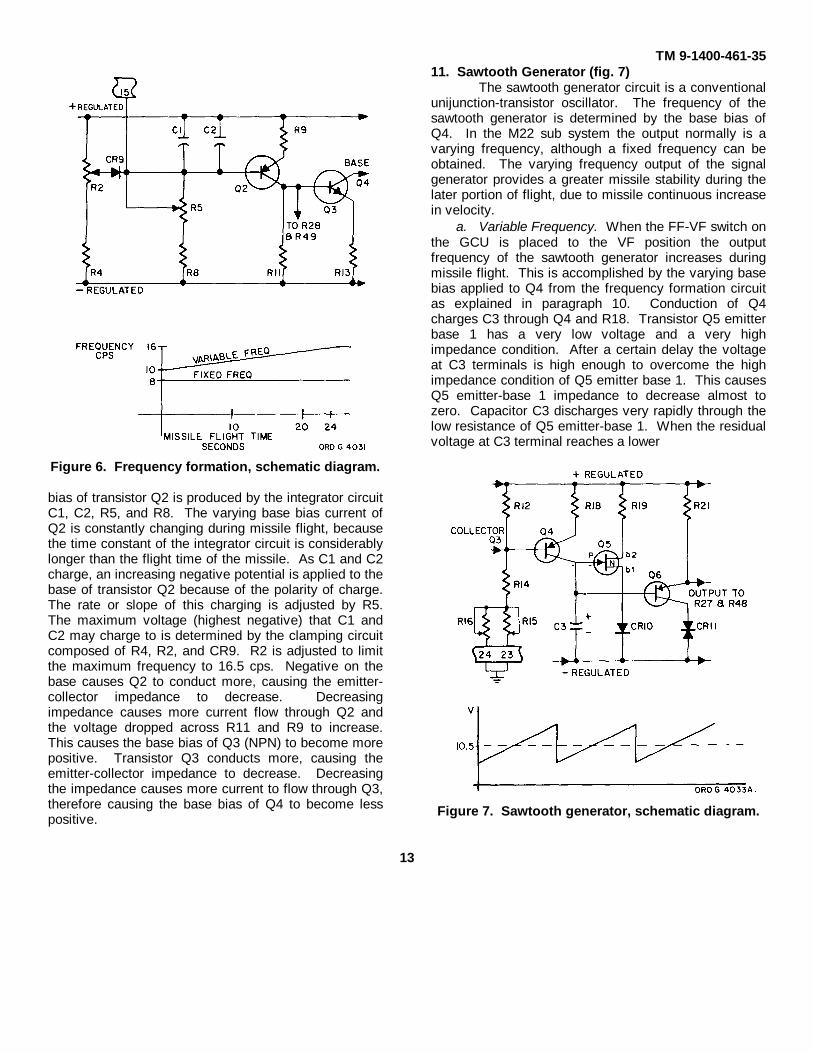
10. Frequency Formation Circuit (fig. 6)The function of the frequency-formation circuit
is to produce the base bias current for transistor Q4.The amplitude of the base bias current determines theoutput frequency of the sawtooth generator circuit. Anincreasing (negative) base bias increases the frequency.The frequency formation circuit is designed to produceeither a variable or fixed bias current, thereby producingeither a variable or fixed frequency.
a. Fixed Bias. Fixed bias, not used for M22subsystem operation, is produced by shorting thefrequency formation circuit through pin 15 to the positiveregulated voltage. This shorts the integrator circuit C1,C2, R5, and R8 and establishes a high positive basebias on transistor Q2. The high base bias decreases theconduction of transistors Q2 and Q3 to cutoff. Fixedbias is accomplished by placing the FF-VF switch (S2)to the FF position.
b. Variable Bias. When the FF-VF switch is placedto the VF position a variable bias is produced by thefrequency formation circuit. Base
12
TM 9-1400-461-35
Figure 6. Frequency formation, schematic diagram.
bias of transistor Q2 is produced by the integrator circuitC1, C2, R5, and R8. The varying base bias current ofQ2 is constantly changing during missile flight, becausethe time constant of the integrator circuit is considerablylonger than the flight time of the missile. As C1 and C2charge, an increasing negative potential is applied to thebase of transistor Q2 because of the polarity of charge.The rate or slope of this charging is adjusted by R5.The maximum voltage (highest negative) that C1 andC2 may charge to is determined by the clamping circuitcomposed of R4, R2, and CR9. R2 is adjusted to limitthe maximum frequency to 16.5 cps. Negative on thebase causes Q2 to conduct more, causing the emitter-collector impedance to decrease. Decreasingimpedance causes more current flow through Q2 andthe voltage dropped across R11 and R9 to increase.This causes the base bias of Q3 (NPN) to become morepositive. Transistor Q3 conducts more, causing theemitter-collector impedance to decrease. Decreasingthe impedance causes more current to flow through Q3,therefore causing the base bias of Q4 to become lesspositive.
11. Sawtooth Generator (fig. 7)The sawtooth generator circuit is a conventional
unijunction-transistor oscillator. The frequency of thesawtooth generator is determined by the base bias ofQ4. In the M22 sub system the output normally is avarying frequency, although a fixed frequency can beobtained. The varying frequency output of the signalgenerator provides a greater missile stability during thelater portion of flight, due to missile continuous increasein velocity.
a. Variable Frequency. When the FF-VF switch onthe GCU is placed to the VF position the outputfrequency of the sawtooth generator increases duringmissile flight. This is accomplished by the varying basebias applied to Q4 from the frequency formation circuitas explained in paragraph 10. Conduction of Q4charges C3 through Q4 and R18. Transistor Q5 emitterbase 1 has a very low voltage and a very highimpedance condition. After a certain delay the voltageat C3 terminals is high enough to overcome the highimpedance condition of Q5 emitter base 1. This causesQ5 emitter-base 1 impedance to decrease almost tozero. Capacitor C3 discharges very rapidly through thelow resistance of Q5 emitter-base 1. When the residualvoltage at C3 terminal reaches a lower
Figure 7. Sawtooth generator, schematic diagram.
13

TM 9-1400-461-35
limit corresponding with the normal high impedancecondition of Q5 emitter base 1, impedance increasesand Q5 ceases conduction. Capacitor C3 is again readyto be recharged and a new integration cycle to begin.The voltage waveform across C3 is coupled to Q6.Transistor Q6, an emitter follower, is the sawtoothcurrent generator output stage. The explanation aboveis for a constant base bias on Q4. As the output fromthe frequency formation circuit increases, the base biasof Q4 increases. Increasing the base bias of Q4 causesC3 to charge and discharge faster, therefore increasingthe sawtooth generator output frequency. Normalvariation of the sawtooth signal under the variablefrequency condition is from 10 to 16.5 cps. ResistorR15 adjusts the initial output frequency of this sawtoothgenerator to the 10 cps lower limit by establishing thebase bias of Q4. Frequency formation circuit outputcurrent is not effective until this bias is overcome.
b. Fixed Frequency. Fixed frequency output willbe explained even though it is not used. This will givethe technician a better understanding of the overallsignal generator module operation. When the FF-VFswitch on the GCU is placed to the FF position theoutput of the sawtooth generator is fixed. This is causedby the frequency formation circuit being shorted asexplained in paragraph 10a. When the frequencyformation circuit is shorted the base bias of Q4 is fixedby voltage divider network R12, R14, and R16. Thebase bias of Q4 is adjustable by R16 and should be setto obtain an 8 cps sawtooth output signal.
12. Impedance Adapter (fig. 8)Voltage functions of pitch (pin 5) and yaw (pin 4)
from the control stick are applied to the impedanceadapters (Q7 and Q8 or Q9 and Q10). Each impedanceadapter is a NPN emitter follower. This configurationprovides impedance matching of both decreasing andincreasing variations in input voltages. Both impedanceadapter circuits are the same, therefore the followingexplanation is applicable to both. A decreasing inputvoltage causes the NPN (Q7 or Q9) transistor to conductless and PNP (Q8 or Q10) to conduct more. The NPNcollector-emitter impedance increases and the PNPcollector-emitter impedance decreases. The voltage
Figure 8. Impedance adapter, schematic diagram.
drop across the NPN increases and across the PNPdecreases. Therefore, the output voltage from theemitters of the NPN and PNP transistors swings in anegative direction. An increasing voltage input causesthe reverse effect on the conduction of the transistors.The output voltage from the emitters of the transistorsswings in a positive direction. The output voltage is fedthrough a phase advance network which couples allsudden commands to the switching amplifiers withoutattenuation. The outputs of the impedance adaptercircuits are linear functions of control stick position andalso of the movement rate. Amplitudes of the outputsignals are adjusted by R24 (pitch) and R45 (yaw).
13. Switching Amplifiers (fig. 9)The purpose of the switching amplifiers is to
produce a square wave output proportional to the linearfunction of control stick position and rate of movement.The amplifiers circuits are so constructed that theyfunction either at cutoff or saturation. The cutoffcondition is caused by the clamping effect of CR12 andCR13. When the input is of sufficient amplitude toovercome the clamping condition the amplifiersimmediately conduct to saturation. There are threeinputs affecting the operation of the switching amplifiers;sawtooth generator (1, fig. 9), impedance adapter (2,fig. 9) and the varying output
14

TM 9-1400-461-35
from the collector of Q2 (3, fig. 9) in the frequencyformation circuit.
a. Sawtooth Generator Input (1, fig. 9). Thesawtooth input applied through R27 and R48 establishesthe conduction and cutoff time of the switchingamplifiers (Q11 and Q15). The amplifiers conduct(saturation) as long as the amplitude of the sawtooth ishigh enough to overcome the clamping effect of CR12and CR13. The above mentioned sawtooth inputestablishes the square wave output. Reference to figure10 will give an illustrated view of the differences in inputand output signals. Let's notice that the amplitude of thesawtooth signal does not change. The reference level(4, fig. 9) at which the sawtooth is riding is the varyingfactor in obtaining desired signal outputs. Resistors R24and R45 adjust the reference level at which thesawtooth rides. As this reference level is changed theup and down (pitch) command portions of the outputsignals differ. Also we must consider the variation in theslope of the sawtooth signal as frequency increases. Asthe sawtooth frequency increases the conduction
Figure 9. Switching amplifier, schematic diagram.
Figure 10. Switching amplifier input and output.
point (Q11 and Q15) will vary because of the change insawtooth linearity due to the change in C3 timeconstant. These variations are explained in thefollowing impedance adapter and frequency formationinput paragraphs.
b. Impedance Adapter Input (2, fig. 9). Theimpedance adapter inputs combines with the frequencyformation input to establish the voltage level at whichthe sawtooth signal rides. The impedance input isproportional to control stick position. Varying the controlstick varies the output of the impedance adapters.Refer to paragraph 21 for mechanical operation of thecontrol stick.
c. Frequency Formation Input (3, fig. 9). Theprimary purpose of the varying input from the frequencyformation circuit is to adjust the voltage level which thesawtooth signal is riding. Previously we established thatthe change in frequency of the sawtooth caused thesawtooth slope to become more linear because ofchanges in applied voltage and resistance. As the slopechanges, the switching amplifier outputs vary, causingan undesirable change in the output signal. This changeis caused by the variation in the linear sawtooth becauseof the voltage and resistance change. The frequencyformation input is combined with the impedance adapter
15

TM 9-1400-461-35
input which adjusts the amplitude of the voltage thesawtooth is riding. Changing this level causes theoutput of the switching amplifiers to be more linear andthe command portions of the output signal to beproportioned correctly.
14. Polarity Control Amplifier (fig. 11)The output from the pitch switching amplifier
Q11 is fed to the polarity control amplifier circuit. Thepurpose of the polarity control amplifier circuit is toestablish the proper polarity of the output signals appliedto the modulator bridge circuit. The switching amplifieroutput (pitch) is applied to the base of Q12. Q12amplifies the input and applies it to the base of Q13.Q13 and Q14 are PNP transistors connected in series,with the collector of Q13 connected to the base of Q14.This configuration causes a 180 degree phase shift inthe output signals from the collectors of the transistors.When Q13 conducts, the higher current output of thecollector drives Q14 to cutoff, causing the collectorcurrent of Q14 to decrease. The reverse effect isobtained when Q13 is cutoff by the signal from pre-amplifier Q12. Tapping the two output signals from thecollectors of Q13
Figure 11. Polarity and amplitude control amplifier.
Figure 12. Bridge modulator, schematic diagram.
and Q14 through CR16 and CR18 respectively,maintains the desired 180 degree phase opposed signaloutput.
15. Amplitude Control Amplifier (fig. 11)The output from the yaw channel switching
amplifier Q15 is fed to the amplitude control amplifiers.The purpose of the amplitude control amplifier is toestablish the proper amplitude of the output signalapplied to the modulator bridge. The switching amplifieroutput (yaw)
16

TM 9-1400-461-35
is applied to the bases of Q16 and Q17. The PNPtransistors conduct at each negative signal input,decreasing the impedance of the transistors causes thevoltage drop across R57 and R58 to increase. Thisproduces a positive going output from the collectors ofQ16 and Q17 which are in phase.
16. Bridge Modulator (fig. 12)The purpose of the bridge modulator is to
convert the pitch and yaw input signals into controlcommand signals.
17. Command SignalsThe command signals determine the corrective
flight path of the missile as follows:a. A positive (6.25 or 18.25) corresponds to a pitch
up command.b. A negative (-6.25 or -18.25) corresponds to a
pitch down command.c. A low positive or negative (6.25 volts)
corresponds to a yaw right command.d. High positive or negative (18.25 volts)
corresponds to a yaw left command.
18. Development of Command SignalsFrom the above paragraph we have established
the desired command signals for missile correctionduring flight. Now let's determine how these signals aredeveloped in the bridge modulator.
a. Pitch Command Signals. The two 180 degreeout of phase outputs from the polarity control amplifiersQ13 and Q14 are applied to the bases of Q19 and Q18,respectively. The latter transistors are flip-flopoperated, one being cutoff when the other is conducting.Conduction and cutoff are determined by the inputsignal shapes. The percentage of each transistorconduction and cutoff time determines the amount ofpitch (up and down) deflection of the missile. Theseoutputs are positive (up command) or negative (downcommand) voltages, dependent upon the direction offlow in the remote control line (pins 11 and 12) and thetransistor conducting. For example, when Q19 isconducting, Q18 is cutoff. The command signal flow isfrom the negative side of the bridge circuit through Q20,R65, out pin 12 to the missile, back through pin 11, R67,and Q19, to the positive side of the bridge circuit. Thisis a negative command signal causing the missile TM 9-1400-46135 to pitch down. Q20 is conducting with a
negative input (yaw signal input) to the base because ofthe voltage tapped from the collector of Q19. Thisvoltage is of sufficient amplitude to cause Q20 toconduct. Q19 will conduct as long as the input pitchcommand signal maintains a negative potential on thebase. The command output signal will change from ahigh current output to a low current output when theinput yaw signal swings positive. This is caused byconduction of both Q20 and Q21. When both conductthe current is split and only a portion of the current istransmitted to the missile coder. This is explained inmore detail in the following paragraph.
b. Yaw Command Signals. The two in phaseoutput signals from the amplitude control amplifiers Q16and Q17 are applied to the base of Q20 and Q21,respectively. The yaw input signals determines theamplitude of the output command signal. Variation inamplitude as related in paragraph 17 determines theyaw left and right missile flight correction. Reference tothe signals illustrated in figure 12 will supplement thefollowing explanation:
(1) At time TO on the yaw input signal Q20 isconducting because of voltage tappedfrom the collector of Q19. With Q19 andQ20 conducting, the current flow path isas explained in the discussion of the pitchcommand signal, paragraph 17a.Reference to TO on the output commandsignal shows that a high voltage (18.25volts) exists. This is because only Q20 isconducting and all the current flow is fedthrough the missile coder. This highamplitude corresponds to a yaw leftcommand.
(2) The above condition prevails until the yawinput signals reach T1. At this point, bothQ20 and Q21 conduct. With bothconducting, the total current is dividedthrough the parallel circuits of thetransistors. One path is to the missile aspreviously explained. The other path isthrough Q21 and R68, then recombinedwith the current from the missile. Thiscauses the output command signalamplitude to reduce. This reduction inamplitude corresponds to a yaw rightcommand.
17

TM 9-1400-461-35
Figure 13. Demodulator, schematic diagram.
(3) Up to this point we have had an outputcommand signal with a positiveamplitude. When the pitch input signalscause Q18 to conduct and Q19 to cutoff,a positive amplitude is produced. This iscaused by the current flow being reversedthrough the missile coder. The path offlow is from negative side of bridgethrough Q21, R68, out pin 11, through themissile coder, back through pin 12, R64and Q18 to the positive side of the bridgemodulator. Also, there is current flowthrough Q20 and R65, causing the currentto be split and the output command signalto have a low positive amplitude.Reference to the command signal outputshows a neutral output condition. Thisoutput will vary as the input voltages fromthe control stick varies.
19. Demodulator (fig. 13)The purpose of the demodulator circuit is to
show proper operation of the signal generator module.This is accomplished by placing the firing switch to thetest (C) position and noting the blinking sequence of thepitch and yaw lamps on the front panel of the GCU.When the firing switch is placed to the C position, thecommand signal output of the signal generator is routedthrough S1-1A and S1-2B segments of the firing switch.This command signal is then fed through pins 9 and 10of the signal generator module to the terminals of R81and R75, and R85 respectively.
a. Yaw Channel. Resistors R81 and R85, of thesame value, maintain Q24 bias as a function of currentvalue without consideration of direction. If the inputcurrent is high, Q24 will be positive biased. The bias ofits emitter is set by CR22 and R83. The voltage dropacross R82 will bias the base of Q25 negatively inrespect to its emitter. The emitter voltage is set byCR24. Biasing Q25 causes conduction and the yawlight to come on indicating a left command. If the inputcurrent is low, Q24 base polarity will be lower than itsemitter. This cuts off Q24 and changes the bias of Q25.Q25 is also cut off causing the yaw light to go offindicating a right command.
b. Pitch Channel. The input current directiondetermines the polarity of Q22 base. If the currentdirection is positive, pin 9 is negative. Q22 base isnegative in respect to its emitter whose voltage isdetermined by CR21. This causes Q22 and Q23 to becutoff. The pitch light, connected to the collector of Q23through pin 14, is off indicating an up command. If thecurrent direction is negative, pin 9 is positive. Q22 baseis positive in respect to its emitter. Q22 conductscausing the bias of Q23 to change. Q23 conducts,causing the pitch light to be on indicating a downcommand.
Section III. MISSILE SELECTION BOX AND CONTROL STICK
20. Missile Selection BoxThe missile selection box contains only switches
which connect straight line circuits. Reference tofigure 14 will provide sufficient information in regard todetailed theory.
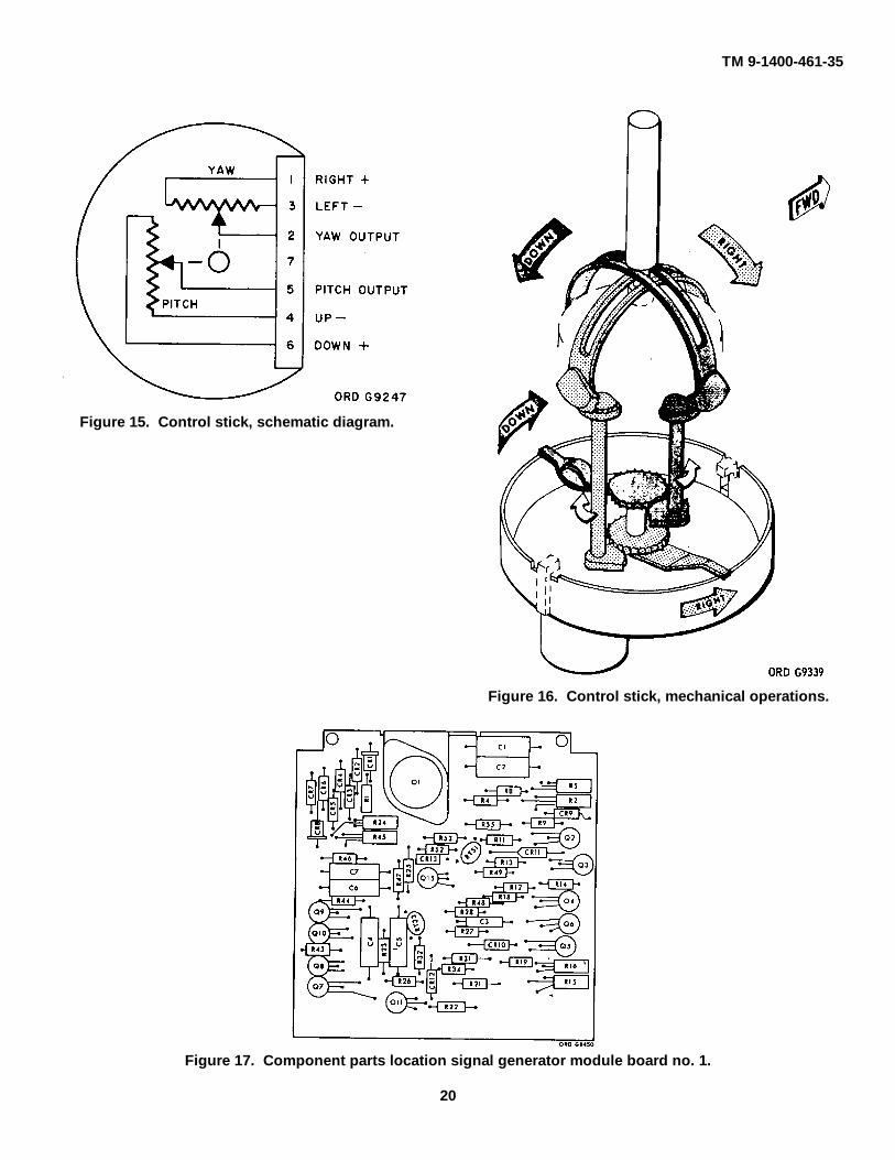
21. Control StickNo detailed theory of the control stick is covered
as the
unit incorporates two variable resistor assemblies(fig. 15) which establish voltage references in respect tothe control stick position. Mechanical theory ofoperation is explained by reference to the mechanicaloperational diagram shown in figure 16.
18

TM 9-1400-461-35
Figure 14. Missile selection box schematic diagram.
19
TM 9-1400-461-35
Figure 15. Control stick, schematic diagram.
Figure 16. Control stick, mechanical operations.
Figure 17. Component parts location signal generator module board no. 1.
20

TM 9-1400-461-35
Figure 18. Component parts location signal generator module board no. 2.
Apparatus List for the Missile Selection Box, Figure 14
Referencedesignator Description Part No.
DS1 LAMP, INCANDESCENT: 28v, 0.04 amp MS 25237-327J1006 CONNECTOR, RECEPTACLE, ELECTRICAL: 10172560
12 male contactsJ1006 CONNECTOR, RECEPTACLE, ELECTRICAL: 10172772
30 female contactsK1-K5 RELAY, ARMATURE 10172555R1-R6 RESISTOR, FIXED: 8 ohms 10172548R7 RESISTOR, FIXED: 4.7 ohms 10172549S1 SWITCH: toggle spst 10172556S2 SWITCH: rotary, 7 circuits, 7 position 101725658S3 SWITCH: key locking 10173698S4-S5 SWITCH: pushbutton 10021991
21

TM 9-1400-461-35CHAPTER 3
INSPECTION
22. ScopeThis chapter provides specific instructions for
the technical inspection by maintenance personnel ofM22 subsystems in the hands of the using organization.It also defines the initial inspection of materiel whenreceived for repair by field maintenance units, in-process inspection during repair, and final inspectionafter repair has been completed.
23. Purpose of InspectionInspections are made for the purpose of (1)
determining the condition of an item as to serviceability,(2) recognizing conditions that would cause failure, (3)assuring proper application of maintenance policies ofprescribed levels, and (4) determining the ability of aunit to accomplish its maintenance and supply mission.
24. Categories of InspectionIn general, three categories of inspection are
performed by maintenance personnel.
a. Command and maintenance inspection.Command maintenance inspections will be performedannually. The purpose of the inspection is to ascertainthe serviceability of equipment, to predict maintenanceand supply requirements, and to determine theadequacy of facilities and effectiveness of procedures.Information obtained during the inspection shouldindicate future requirements for depot maintenance andfor replacement, as well as disclose immediate needsfor maintenance and application of modification workorders. During inspections, corrections of deficiencieswill be made on the spot when practical. For additionalinformation relative to these inspections and the formsto be
used, refer to AR 750-8. Command maintenanceinspection procedures are detailed in TB 9-212/1.
b. Shop Inspection.
(1) Initial inspection. This inspection isperformed immediately upon receipt ofmateriel in the maintenance shops. Thisinspection determines the disposition ofthe materiel insofar as prompt repair,when work can be accomplished by fieldmaintenance units, or evacuation to depotmaintenance units when the work is moreextensive.
(2) In-process inspection. This inspection isperformed in the process of repairing themateriel and its components. It insuresthat the workmanship is in accordancewith approved methods and proceduresand that deficiencies not disclosed by theinitial inspection are found and corrected.
(3) Final inspection. This is an acceptanceinspection performed by a final inspectorafter repair has been completed to insurethat the materiel is acceptable for returnto the user.
c. Preembarkation Inspection. This inspection isconducted on materiel in alerted units scheduled foroversea duty to insure that such materiel will notbecome unserviceable or worn out in a relatively shorttime. It prescribes a higher percentage of remainingusable life in serviceable materiel to meet a specificneed beyond minimum serviceability. Preembarkationinspection procedures are those detailed for commandmaintenance inspection outlined in TB 9-212/1.
23

TM 9-1400-461-35CHAPTER 4
TROUBLESHOOTING25. General
a. Troubleshooting is a systematic method forfinding malfunctioning components. Thetroubleshooting procedures contained in this chapter arefor use by direct support, general support, and depotmaintenance personnel.
b. Troubleshooting procedures cover all majorcomponents of the M22 subsystem and the cable andharness assemblies. Troubleshooting procedures arenot covered for items of the fire control installation asthese items should be returned through normal supplychannels for depot reconditioning.
c. Troubleshooting is accomplished by substitutingthe suspected defective component into
the test console in the shop van (TM 9-1400-461-15/1).Test console cabling is so constructed that the defectivecomponent can be placed upon the bench and checksperformed with a minimum of difficulty.
d. The troubleshooting procedures given in eachtable will identify the circuit where the malfunction existsand the most probable cause.
26. Troubleshooting Procedure for MissileSelection Box (10172477)
Table 1 gives the troubleshooting procedure forthe missile selection box. See figure 14 for theelectrical schematic of the missile selection box.
Table 1. Troubleshooting Procedures /or Missile Selection BoxPreparation for test:
a. Equipment required:(1) Test console (TM 9-4935-461-15/1)(2) Multimeter TS-352,/U(3) Stop watch
b. Test setup:(1) Insure proper operation of test console by performing operational check procedures in TM 9-4935-461-
15/1.(2) Substitute missile selection box under test in place of the missile selection box on the test console.
Step Operation and normal indication Corrective action
1 Apply power to the test console and set PWR-ON-OFFswitch to the ON position.
NORMAL and JETT indicator lamps on a. Check NORMAL and JETTtest console glow. lamps and fuses.
b. Check input circuitry frompower supply to console(TM 9-4935-461-15/1).
2 Set the missile selections box key switch to the onposition.
Missile selection box power lamp glows. a. Check the lamp on the selec-tion box.
b. Check power circuit (fig. 14).
3 Connect test set to test console DUMMY LAUNCHERconnector no. 1 .
25

TM 9-1400-461-35Table 1. Troubleshooting Procedures for Missile Selection Box--Continued.
Step Operation and normal indication Corrective action
4 Set the selection switch to the missile selection box toposition 1.
Note. Firing switch on GCU should be in the 0 position before performing step 6.
5 Move and hold the GCU firing switch to the IG position.DUMMY LAUNCHER no. 1 EXPLOSIVE a. Check the lamp.CART COPIMAND lamp on test console b. Check and replace defectiveglows. component of gyro igni-
tion circuit (fig. 14).6 Repeat step 5 for all positions of missile selection
switch and return to position 1 when complete.
EXPLOSIVE CART COMMAND lamps Same as 5 above.2-6 glow, coinciding with missile selec-tion switch position.
7 Set the MISSILE UNLOCK switches on test consoleto the ON position and hold the firing switch on theGCU to the UG position.
The UG lamp on the test set glows. a. Check lamp on test set.b. Check and replace defective
component of gyro uncagecircuit (fig. 14).
8 Repeat step 7 for all other positions of missile selec-tion switch and return to position 1 when complete.
The UG lamp on the test set goes off and Same as 7 above.remains off until the missile selection (Check for shorts).switch is returned to position 1.
9 Move and hold the GCU firing switch to the IFBposition.
The UG lamp on the test set goes off and a. Check lamp on test set.the IFB lamp glows. b. Check and replace defective
component of igniter flareignition circuit (fig. 14).
10 Repeat step 9 for all other positions of the missile Same as step 9.selection switch and return to position 1 when com- (Check for shorts).plete.
11 Release the GCU firing switch and let it rotate to the Fposition.
12 Press and hold the WIRES jettison switch on the mis-sile selection box while rotating the missile selectionswitch through all positions.
The WJ lamp on the test set glows only a. Check lamp on test set.on position 1. b. Check and replace defective
component of wire jetti-son circuit (fig. 14).
13 Repeat steps 7 through 12 with the test set connectedto each of the remaining DUMMY LAUNCHERconnectors (2-6). Position the missile selectionswitch to coincide with the test set connection andreturn to this position when the test is complete.
26

TM 9-1400-461-35Table 1. Troubleshooting Procedures for Missile Selection Box - Continued.
Step Operation and normal indication Corrective action
The IG, UG, IFB, and WJ 1 lamps on the Same as steps 5 through 7.test set should glow only when the missileselection switch coincides with the DUM-MY LAUNCHER connector to which thetest set is connected.
14 Press and hold the SIN switch on the missile selectionbox while rotating the missile selection switchthrough all positions
The EXPLOSIVE BOLT COMMAND a. Check lamps and replacelamps (1-6) on the test console glows b. Check and replace defectivecoinciding with missile selection switch component of single jetti-positions (1-6). son circuit (fig. 14).
15 Press and hold the TOT switch on the missile selectionbox while rotating the missile selection switchthrough all positions.
All EXPLOSIVE BOLT COMMAND a. Check lamps and replacelamps (1-6) glow with missile selection b. Check and replace defectiveswitch in all positions (1-6). component of the total
jettison circuit (fig. 14).
16 Move the GCU firing switch to the 0 position and theFF/VF switch to the VF position.
17 Set the test set selector switch to the F position
18 Lift and release the GCU firing switch while watchingthe test set
Test set meter pointer initially indicates Check and replace the missile10 cps then increases to 165 cpa. guidance signal circuit com-
ponent (fig. 14).
27. Troubeshooting Procedure for the GuidanceControl UnitTable 2 gives the troubleshooting procedures
for the guidance control unit See figures 2, 17, 18, andTM 9-1400 461-20 for electrical schematic, location ofcomponents, and controls.
Table 2. Troubleshooting Procedures for the GCU.Preparation for test:
a. Equipment required:(1) Test console (TM 9-493561-15/1)(2) Multimeter TS-352/U(3) Oscilloscope AN/UPM-117
b. Test setup:(1) Insure proper operation of test console by performing operational check procedures in TM 9-4935461-15/1.(2) Substitute GCU under test in place of the GCU on the test console by connecting cables on top of console
GCU to unit under te3t sitting on the bench in front of test console
27

TM 9-1400-461-35
Table 2. Troubleshooting Procedures for the GCU-Continued.
Step Operation and normal indication Corrective action
1 Apply power to the test console and set the PWR-ON-OFF switch to the ON position.
NORMAL and JETT indicator lamps on a. Check lamps and fuses.the test console glow. b. Check input circuitry from
power supply to console(TM 9-4935-461-15/1).
2 Set the missile selection box key switch to the onposition.
Missile selection box power lamp glows. a. Check the lamp on the selec-tion box.
b. Check power circuit fig. 15).3 Connect the test set to the test console DUMMY
LAUNCHER plug no. 1.
4 Set the missile selection switch on the missile selectionbox to position 1.
Note. The firing switch on the GCU must be held in the C (test) position while performing steps 5 through 9.
5 Move and hold the firing switch on the GCU to the C(test) position.
The voltmeter on the GCU indicates a. Check and replace defectivewithin the red band. voltmeter.
b. Check power input circuit(fig. 2).
The pitch (white) lamp on the GCU flick- a. Check lamps.ers dimly. The yaw (orange) lamp flickers b. Defective signal generatorwith a medium intensity. module (perform table 3).
c. Defective power circuit inGCU (fig. 2).
6 Position the control stick to the maximum climb posi-tion (pull back on stick).
The pitch (white) lamp goes off (Disre- Defective signal generator mod-gard the orange lamp). ule (perform table 3).
7 Position the control stick to the maximum dive position(push forward on stick).
The pitch (white) lamp flickers with Same as step 6 above.medium intensity.
8 Position the control stick to the maximum yaw left(move stick to the left) position.
The yaw (orange) lamp glows with a Same as step 6 above.bright intensity (on all the time).
9 Position the control stick to the maximum right yawposition (move stick to the right).
The yaw (orange) lamp goes off.
10 Move and hold the GCU firing switch to the 1G position.
The EXPLOSIVE CART COMMAND a. Check lamp.lamp number 1 glows. b. Replace defective compo-
nent in GCU unit (fig. 2).
28

TM 9-1400-461-35
Table 2. Troubleshooting Procedures for the GCU-Continued.
Step Operation and normal indication Corrective action
11 Set the number 1 MISSILE UNLOCK switch to theON position.
The IG lamp on the test set glows. Same as step 10 above.
12 Move and hold the GCU firing switch to the UG posi-tion.
The UG lamp on the test set glows and Same as step 10 above.the IG lamp goes off.
13 Move and hold the GCU firing switch to the FB position.
The IFB3 lamp on the test set glows and Same as step 10 above.the UG lamp goes off.
14 Set the TEST SET FUNCTION switch to F then allowthe GCU firing switch to rotate to the F positionwhile watching the test set.
Test set meter pointer initially indicates Same as step 6.10 cps then increases to 16.5 cps 21 to 23seconds after the GCU firing switchreaches the F position.
15 Set the function switch on the test set to the P position.
The meter on the test set indicates be- Same as step 6 above.tween 25 and 35 percent left of zero.
16 Move the control stick to the maximum climb position.
The meter on the test set indicates be- Same as step 6 above.tween 87 and 100 percent left of zero.
17 Slowly move the control stick from the maximumclimb position to the maximum dive position.
The meter moves smoothly from left to Same as step 6 above.right and settles between 13 and 33 per-cent right of zero.
Note. A steady quiver of the needle is normal.
18 Set the function switch on the test set to the Y positionand release the control stick.
The meter on the test set indicates be- Same as step 6 above.tween --10 and +10.
19 Move and hold the control stick to the maximum left(yaw) position.
The meter indicates 83 to 100 percent left Same as step 6 above.of zero.
20 Slowly move the control stick from the maximum left(yaw) position to the maximum right (yaw) position.
The meter moves smoothly from left to Same as step 6 above.right and settles between 83 and 100 per-cent right of zero.
21 Set the function switch on the test set to the V position,and the Hi V/Lo V switch to the Hi V position.
29

TM 9-1400-461-35
Table 2. Troubleshooting Procedures for the GCU - Continued
Step Operation and normal indication Corrective action
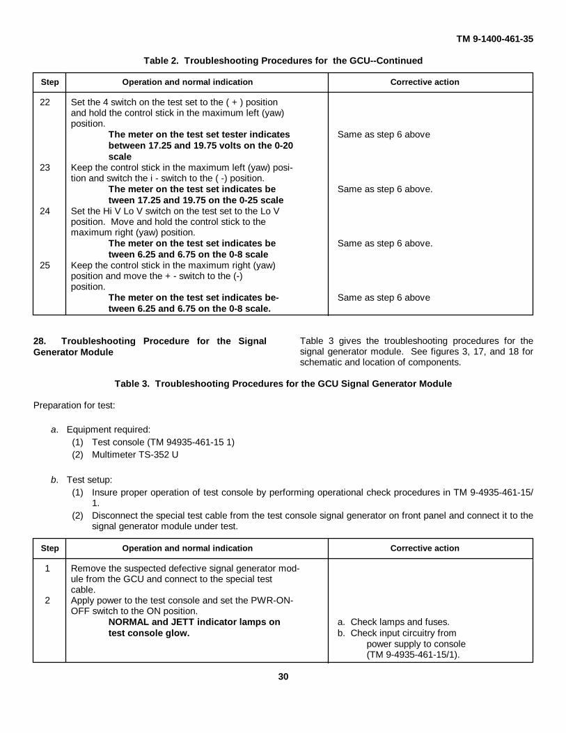
22 Set the - switch on the test set to the ( + ) positionand hold the control stick in the maximum left (yaw)position.
The meter on the test set tester indicates Same as step 6 above.between 17.25 and 19.75 volts on the 0-20scale
23 Keep the control stick in the maximum left (yaw) posi-tion and switch the + - switch to the (-) position.
The meter on the test set indicates be- Same as step 6 abovetween 17.25 and 19.75 on the 025 scale
24 Set the Hi V Lo V switch on the test set to the Lo Vposition. Move and hold the control stick to themaximum right (yaw) position.
The meter on the test set indicates be- Same as step 6 above.tween 6.25 and 6.75 on the 0-8 scale
25 Keep the control stick in the maximum right (yaw)position and move + - the switch to the (-)position.
The meter on the test set indicates be- Same as step 6 above.tween 625 and 6.75 on the 0-8 scale.
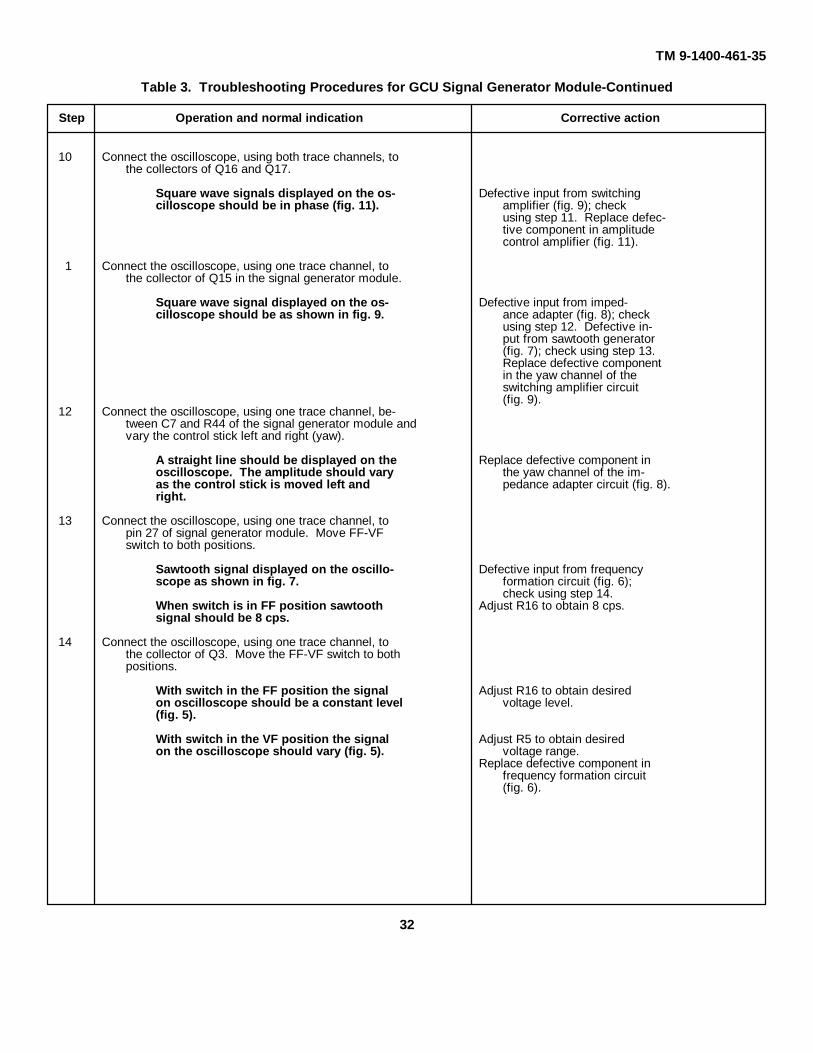
28. Troubleshooting Procedure for the for the signal generator module See figures 3, 17, and 18Signal Generator Module for schematic and location of components.
Table 3 gives the troubleshooting procedures
Table 3. Troubleshooting Procedures for the GCU Signal Generator ModulePreparation for test:
a. Equipment required:(1) Test console (TM 9-4935-461-15/1)(2) Multimeter TS-352/U
b. Test setup:(1) Insure proper operation of test console by performing operational check procedures in TM 9-4935-461-
15/1.(2) Disconnect the special test cable from the test console signal generator on front panel and connect it to the
signal generator module under test
Step Operation and normal indication Corrective action
1 Remove the suspected defective signal generator mod-ule from the GCU and connect to the special testcable.
2 Apply power to the test console and set the PWR-ON-OFF switch to the ON position.
NORMAL and JETT indicator lamps on a. Check lamps and fuses.test console glow. b. Check input circuitry from
power supply to console(TM 9-4935-461-15/1).
30

TM 9-1400-461-35
Table 3. Troubleshooting Procedures for GCU Signal Generator Module - Continued.
Step Operation and normal indication Corrective action
3 Move the GCU firing switch to the F position.4 Connect the oscilloscope, using one trace channel, be-
tween R64 and R65.
Signal should be as shown in figure 10. Defective component in bridgemodulator circuit (fig. 3).
5 With the oscilloscope still connected between R64 andR65 move the control stick forward and backward(pitch).
Percentage of positive and negative por- Replace defective pitch channeltions of the output signal on the oscillo- component in bridge modu-scope should change as the control stick lator (fig. 12).is moved. Defective input from polarity
control amplifier (fig. 11);check using step 7.
6 With the oscilloscope still connected between R64 andR65 move the control stick left and then right (yaw).
Percentage of signal amplitude should Replace defective yaw channelchange as the control stick is moved. components in the bridge
modulator (fig. 12). Defec-tive input from amplitudecontrol amplifier (fig. 11);check using step 10.
7 Connect the oscilloscope, using both trace channels,between R71 and R72; and R61 and pin 21 of thesignal generator module.
Square wave signals on the oscilloscope Defective input from switchingshould be 180 degrees out of phase with a amplifier (fig. 9); checkvoltage amplitude of 75 (fig. 10). using step 13. Replace defec-
tive component in polaritycontrol amplifier (fig. 11).
8 Connect the oscilloscope, using only one trace channelto the collector of Q11 in the signal generator module.
Square wave signal displayed on oscillo- Defective input from imped-scope should be as shown in figure 9. ance adapter (fig. 8); check
using step 9. Defective inputfrom sawtooth generator (fig. 7);check using step 13. Re-place defective component inthe pitch channel of theswitching amplifier circuit(fig. 9).
9 Connect the oscilloscope, using one trace, between C5and R23 of the signal generator module and vary thecontrol stick backward and forward (pitch).
A straight line should be displayed on the Replace defective component inoscilloscope. The amplitude should vary pitch impedance adapter cir-as the control stick is moved backward cuit (fig. 8).and forwards.
31
TM 9-1400-461-35
Table 3. Troubleshooting Procedures for GCU Signal Generator Module-Continued
Step Operation and normal indication Corrective action
10 Connect the oscilloscope, using both trace channels, tothe collectors of Q16 and Q17.
Square wave signals displayed on the os- Defective input from switchingcilloscope should be in phase (fig. 11). amplifier (fig. 9); check
using step 11. Replace defec-tive component in amplitudecontrol amplifier (fig. 11).
1 Connect the oscilloscope, using one trace channel, tothe collector of Q15 in the signal generator module.
Square wave signal displayed on the os- Defective input from imped-cilloscope should be as shown in fig. 9. ance adapter (fig. 8); check
using step 12. Defective in-put from sawtooth generator(fig. 7); check using step 13.Replace defective componentin the yaw channel of theswitching amplifier circuit(fig. 9).
12 Connect the oscilloscope, using one trace channel, be-tween C7 and R44 of the signal generator module andvary the control stick left and right (yaw).
A straight line should be displayed on the Replace defective component inoscilloscope. The amplitude should vary the yaw channel of the im-as the control stick is moved left and pedance adapter circuit (fig. 8).right.
13 Connect the oscilloscope, using one trace channel, topin 27 of signal generator module. Move FF-VFswitch to both positions.
Sawtooth signal displayed on the oscillo- Defective input from frequencyscope as shown in fig. 7. formation circuit (fig. 6);
check using step 14.When switch is in FF position sawtooth Adjust R16 to obtain 8 cps.signal should be 8 cps.
14 Connect the oscilloscope, using one trace channel, tothe collector of Q3. Move the FF-VF switch to bothpositions.
With switch in the FF position the signal Adjust R16 to obtain desiredon oscilloscope should be a constant level voltage level.(fig. 5).
With switch in the VF position the signal Adjust R5 to obtain desiredon the oscilloscope should vary (fig. 5). voltage range.
Replace defective component infrequency formation circuit(fig. 6).
32

TM 9-1400-461-3529. Troubleshooting Procedures for the ControlStick
Table 4 covers the troubleshooting proceduresfor the control stick. See figure 15 for electricalschematic diagrams.
30. Troubleshooting Procedures for the Cable andHarness Assemblies
The only required troubleshooting proceduresfor the cable and harness assemblies are continuitychecks. These checks can be accomplished
by reference to the cabling diagram in TM 9-1400-461-20.
31. Troubleshooting Procedures for Fixed HousingTable 5 gives the troubleshooting procedures for
the fixed housing assembly.
32. Troubleshooting Procedures for the LauncherTable 6 gives the troubleshooting procedures for
the launcher.
Table 4. Troubleshooting Procedures for the Control Stick-Continued.
Preparation for test:a. Equipment required:
(1) Test console (TM 9-4935-461-15/1)(2) Multimeter TS-352/U
b. Test setup:(1) Insure proper operation of test console by performing operational check procedures in TM 9-4935-461-
15/1.(2) Substitute the control stick under test in place of the control stick on the test console.
Step Operation and normal indication Corrective action
1 Apply power to the test console and set the PWR-ON-OFF switch to the ON position.
NORMAL and JETT indicator lamps on a. Check lamps and fuses.test console glow. b. Check input circuitry from
the power supply to theconsole (TM 9-4935-461-15/1).
2 Set the key switch on the missile selection box to theON position.
Missile selection box power lamp glows. Check and replace defectivelamp.
3 Connect the test set to DUMMY LAUNCHER no. 1.4 Set the missile selection switch to position 1.5 Position the firing switch on the GCU to F position.6 Set the function switch on the test set to the P position.
The meter on the test set indicates be- Defective resistor in the con-tween 25 and 35 percent left of zero. trol stick (perform step 12
through 17).7 Move the control stick to the maximum climb (back-
ward) position.
The meter on the test set indicates be- Same as step 6 above.tween 87 and 100 percent left of zero.
33

TM 9-1400-461-35
Table 4. Troubleshooting Procedures for the Control Stick-Continued.
Step Operation and normal indication Corrective action
8 Slowly move the control stick from the maximum climb(backward) position to the maximum dive (for-ward)position.
The meter moves smoothly from left to Same as step 6 above.right and settles between 13 and 33 per-cent right of zero.
Note. A steady quiver of the needle is normal.
9 Set the function switch on the test set to the Y positionand release the control stick.
The meter on the test set indicates be- Same as step 6 above.tween -10 and + 10.
10 Move and hold the control stick to the maximum left(yaw) position.
The meter indicates 83 to 100 percent left Same as step 6 above.of zero.
11 Slowly move the control stick from the maximum left(yaw) position to the maximum right (yaw) position.
The meter moves smoothly from left to Same as step 6 above.right and settles between 83 and 100 per-cent right of zero.
Note. The remainder of this table is resistance value checks of the control stick resistors. Perform only if a malfunction was detected during above troubleshooting.
12 Connect multimeter between pin I and pin 3 of thecontrol stick-
Multimeter should indicate a resistance Replace defective yaw controlof 25K ohms resistor (par. 37).
13 Connect multimeter between pins 4 and 6 of the controlstick
Multimeter should indicate a resistance Replace defective pitch controlof 25K ohms resistor (par. 37).
14 Connect multimeter between pins 2 and 3 and movecontrol stick left and right
Multimeter should indicate a resistance Replace defective wiper yawof 15.2K ohms; then increase as control control resistor (par. 37).stick is moved left and decrease whenmoved right
15 Connect multimeter between pins 1 and 2 and movecontrol stick left and right
Multimeter should indicate 12.5K ohms; Same as 14 above.then decrease as control stick is movedleft and increase when moved right
16 Connect multimeter between pins 5 and 6 and movecontrol stick forward then backwards.
Multimeter should indicate a resistanceof 12.5K ohms; then increase as controlstick is moved forward and backwards
34

TM 9-1400-461-35Table 4. Troubleshooting Procedures for the Control Stick - Continued
Step Operation and normal indication Corrective action
17 Connect multimeter between pins 4 and 5 and movecontrol stick forward then backward
Multimeter should indicate a resistance Same as 16 aboveof 12.5 ohms; the decrease as the con-trol stick is moved forward and increasewhen moved backward
Table 5. Troubleshooting Procedures for the Fixed Housing
Preparation for test:a. Equipment required:
(1) Test console (TM 9-4935-461-15/1)(2) Multimeter TS352/U(3) Test set (launching and guidance command test set)
b. Test setup:(1) Insure proper operation of test console by performing operational check procedures in TM 9-4935-461-
15/1.(2) Substitute the fixed housing under test in place of the fixed housing on the test console.
Step Operation and normal indication Corrective action
1 Apply power to the test console and set the PWRON-OFF switch to the ON position.
NORMAL and JETT indicator lamps on a Check lamps and fusestest console glow. b. Check input circuitry from
power supply to console(TM 94935461-15/1).
2 Connect the test set to the launcher missile connector.
3 Install the explosive cartridge tester into the Iauncherassembly with the missile looking over in the un-locked position.
4 Connect the explosive bolt circuit tester to the con-nector in the fixed housing.
5 Set the No. 6 LAUNCHER SELECTOR switch toREAL LAUNCHER position and the missile selec-tion box to position 6.
6 Reset the firing switch to the 0 position and then holdthe firing switch on the GCC to the IG position.
Explosive cartridge tester lamp and the Check and replace defectiveIG lamp - the test set glows. cable assembly (par. 38).
7 Move and hold the firing switch to the UG position.
IG lamp goes off and the UG lamp glows. Same as step 6 above.
8 Move and hold the firing switch to the FB position.
UG lamp goes off and the IFB lamp glows. Same as step 6 above.
9 Reset the firing switch to the 0 position.
10 Press the WIRES itch on the missile selection box.
WJ lamp the test set glows. Same a step 6 above.35

TM 9-1400-461-35Table 5.-Troubleshooting Procedures for the Fixed Housing-Continued.
Step Operation and normal indication Corrective action
11 Press the SIN jettison switch on the missile selectionbox.
The explosive bolt circuit tester lamp Check and replace defectiveglows. connector.
12 Set the test set selector switch to F position.13 Lift and release the GCU firing switch.
Test set meter pointer indicates 10 cps Same as step 6 above.initially, then increases to 16.5 cps.
Table 6. Troubleshooting Procedures for the LauncherPreparation for test:
a. Equipment required:(1) Test console (TM 9-4935-461-15/1)(2) Multimeter TS-352/U(3) Test set (launching and guidance command test set)
b. Test setup:(1) Insure proper operation of test console by performing operational check procedures in TM 9-4935-461-
15/1.(2) Substitute the launcher under test in place of the launcher on the test console.
Step Operation and normal indication Corrective action
1 Apply power to the test console and set the PWR-ON-OFF switch to the ON position.
NORMAL and JETT indicator lamps on a. Check lamps and fuses.test console glows. b. Check input circuitry from
power console (TM 9-4935-461-15/1).
2 Connect the test set to the launcher missile connector.3 Install the explosive cartridge tester into the launcher
assembly with the missile locking lever in the upposition.
4 Set the missile selection switch on the missile selectionbox to position 6 and No. 6 LAUNCHER SELEC-TOR on the test console to the REAL LAUNCHERposition.
5 Reset the firing switch to the 0 position and then holdthe firing switch to the IG position and the missilelocking lever to the down position.
Explosive cartridge tester lamp glows. Check and replace defectivemicroswitch (par. 39) orlauncher.
6 Release the missile locking lever.The IG lamp on the test set glows. Same as step 5 above.
7 Move and hold the firing switch to the UG position.IG lamp goes off and UG lamp glows. Same as step 5 above.
8 Move and hold the firing switch to the FB position.UG lamp goes off and IFB lamp glows. Same as step 5 above.
36

TM 9-1400-461-35
Table 6. Troubleshooting Procedures for the Launcher-Continued.
Step Operation and normal indication Corrective action
9 Reset the firing switch to the 0 position.10 Press the WIRES switch on the missile selection box.
WJ lamp on the test set glows. Same as step 5 above.11 Set the test set selector switch to the F position.12 Lift and release the GCU firing switch.
Test set meter pointer indicates 10 cps Same as step 5 above.initially, then increases to 16.5 cps.
Figure 19-Legend.37

TM 9-1400-461-35
Figure 19. Missile selection box - disassembled view.38

TM 9-1400-461-35CHAPTER 5
CORRECTIVE MAINTENANCE33. Scope
a. This chapter contains maintenance informationcovering the M22 subsystem that is within the scope ofdirect support, general support, and depot maintenancepersonnel. The scope of maintenance is determined bythe maintenance allocation chart in TM 9-1400461-20and the listing of repair parts and special toolsauthorized in TM 9-1400-461-35P.
b. No instructions are given for removal,disassembly, or installation of chassis-mounted orpanel-mounted parts that are soldered or fastened in theusual way. For information on solder and soldering referto TB SIG 222.
36. Removal and Installation of Guidance ControlUnit Component Parts
Removal and installation of component parts ofthe GCU are obvious upon inspection. Refer tofigures 21, 22, and 23 for GCU component removal andinstallation. Refer to figures 17 and 18 for signalgenerator module component removal and installation.
Caution:When removing and installing thesignal generator module from theGCU care should be taken to preventdamage to components on theprinted circuit boards. Slowly workthe module around until it can beremoved
Figure 20. Missile selection box.
34. General InstructionsRemove parts only as required to make repairs.
Do not remove serviceable parts unless you must do soto get to the defective parts.
35. Removal and Installation of Missile SelectionBox Component Parts
Removal and installation of components areobvious upon inspection. Location of component partsis shown in figure 19 and 20. Reference designatorsused on the component parts diagram are the same asthose used on the schematic diagram as illustrated infigure 14.
and installed without rubbing against the side of theGCU.
37. Removal and Installation of Control StickComponent PartsRemoval and installation of component parts of
the control stick are obvious upon inspection. Refer tofigure 24 for control stick component removal andinstallation.
Caution:When installing the control stickcomponents insure that theconnector, small screw hole key, andname plate are lined up.
39

TM 9-1400-461-35
Figure 21. Guidance control unit, exploded view.40

TM 9-1400-461-35
Table 1. Troubleshooting Procedures for Missile Selection Box--Continued
Step Operation and normal indication Corrective action
The IG, UG, IFB, and WJ lamps on the Same as steps 5 through 7.test set should glow only when the missileselection switch coincides with the DUM-MY LAUNCHER connector to which thetest set is connected.
14 Press and hold the SIN switch on the missile selectionbox while rotating the missile selection switchthrough all positions
The EXPLOSIVE BOLT COMMAND a. Check lamps and replace.Lamps (1-6) on the test console glows b. Check and replace defectivecoinciding with missile selection switch component of single jetti-positions (1-6). son circuit (fig. 14).
15 Press and hold the TOT switch on the missile selectionbox while rotating the missile selection switchthrough all positions.
All EXPLOSIVE BOLT COMMAND a. Check lamps and replace.lamps (1-6) glow with missile selection b. Check and replace defectiveswitch in all positions (1-6). component of the total
jettison circuit (fig. 14).16 Move the GCU firing switch to the 0 position and the
FF/VF switch to the VF position17 Set the test set selector switch to the F position-18 Lift and release the GCU firing switch while watching
the test setTest set meter pointer initially indicates Check and replace the missile10 cps then increases to 16.5 cps. guidance signal circuit com-
ponent (fig. 14).
27. Troubleshooting for the Guidance Control UnitTable 2 gives the troubleshooting procedures for theguidance control unit See figures 2, 17, 18, and TM 9-
140-461-20 for electrical schematic, location ofcomponents, and controls
Table 2. Troubleshooting Procedures for the GCU
Preparation for test:
a. Equipment required:
(1) Test console (TM 9-4935-461-15/1)(2) Multimeter TS-352/U(3) Oscilloscope AN/UPM-117
b. Test setup:
(1) Insure proper operation of test console by performing operational check procedures in TM 9-4935-461-15/1.
(2) Substitute GCU under test in place of the GCU on the test console by connecting cables on top of consoleGCU to unit under test sitting on the bench in front of test console.
27

TM 9-1400-461-35
Table 2. Troubleshooting Procedures for the GCU-Continued.
Step Operation and normal indication Corrective action
1 Apply power to the test console and set the PWR-ON-OFF switch to the ON position.
NORMAL and JETT indicator lamps on a. Check lamps and fuses.the test console glow. b. Check input circuitry from
power supply to console(TM 9-4935-461-15/1).
2 Set the missile selection box key switch to the onposition.
Missile selection box power lamp glows. a. Check the lamp on the selec-tion box.
b. Check power circuit fig. 15).3 Connect the test set to the test console DUMMY
LAUNCHER plug no. 1.4 Set the missile selection switch on the missile selection
box to position 1.
Note. The firing switch on the GCU must be held in the C (test) position while performing steps 5 through 9.
5 Move and hold the firing switch on the GCU to the C(test) position.
The voltmeter on the GCU indicates a. Check and replace defectivewithin the red band. voltmeter.
b. Check power input circuit(fig. 2).
The pitch (white) lamp on the GCU flick- a. Check lamps.ers dimly. The yaw (orange) lamp flickers b. Defective signal generatorwith a medium intensity. module (perform table
3).c. Defective power circuit in
GCU (fig. 2).6 Position the control stick to the maximum climb posi-
tion (pull back on stick).The pitch (white) lamp goes off (Disre- Defective signal generator mod-gard the orange lamp). ule (perform table 3).
7 Position the control stick to the maximum dive position(push forward on stick).
The pitch (white) lamp flickers with Same as step 6 above.medium intensity.
8 Position the control stick to the maximum yaw left(move stick to the left) position.
The yaw (orange) lamp glows with a Same as step 6 above.bright intensity (on all the time).
9 Position the control stick to the maximum right yawposition (move stick to the right).
The yaw (orange) lamp goes off.10 Move and hold the GCU firing switch to the 1G position.
The EXPLOSIVE CART COMMAND a. Check lamp.lamp number 1 glows. b. Replace defective compo-
nent in GCU unit (fig. 2).
28

TM 9-1400-461-35
Table 2. Troubleshooting Procedures for the GCU-Continued.
Step Operation and normal indication Corrective action
1 Set the number 1 MISSILE UNLOCK switch to theON position.
The IG lamp on the test set glows. Same as step 10 above.12 Move and hold the GCU firing switch to the UG posi-
tion.The UG lamp on the test set glows and Same as step 10 above.the IG lamp goes off.
13 Move and hold the GCU firing switch to the FB position.The IFB lamp on the test set glows and Same as step 10 above.The UG lamp goes off.
14 Set the TEST SET FUNCTION switch to F then allowthe GCU firing switch to rotate to the F positionwhile watching the test set.
Test set meter pointer initially indicates Same as step 6.10 cps then increases to 16.5 cps 21 to 23seconds after the GCU firing switchreaches the F position.
15 Set the function switch on the test set to the P position.The meter on the test set indicates be- Same as step 6 above.tween 25 and 35 percent left of zero.
16 Move the control stick to the maximum climb position.The meter on the test set indicates be- Same as step 6 above.tween 87 and 100 percent left of zero.
17 Slowly move the control stick from the maximumclimb position to the maximum dive position.
The meter moves smoothly from left to Same as step 6 above.right and settles between 13 and 33 per-cent right of zero.
Note. A steady quiver of the needle is normal.
18 Set the function switch on the test set to the Y positionand release the control stick.
The meter on the test set indicates be- Same as step 6 above.tween -10 and +10.
19 Move and hold the control stick to the maximum left(yaw) position.
The meter indicates 83 to 100 percent left Same as step 6 above.of zero.
20 Slowly move the control stick from the maximum left(yaw) position to the maximum right (yaw) position.
The meter moves smoothly from left to Same as step 6 above.right and settles between 83 and 100 per-cent right of zero.
21 Set the function switch on the test set to the V position,and the Hi V/Lo V switch to the Hi V position.
29
TM 9-1400-461-35
Table 2. Troubleshooting Procedures for the GCU--Continued
Step Operation and normal indication Corrective action
22 Set the 4 switch on the test set to the ( + ) positionand hold the control stick in the maximum left (yaw)position.
The meter on the test set tester indicates Same as step 6 abovebetween 17.25 and 19.75 volts on the 0-20scale
23 Keep the control stick in the maximum left (yaw) posi-tion and switch the i - switch to the ( -) position.
The meter on the test set indicates be Same as step 6 above.tween 17.25 and 19.75 on the 0-25 scale
24 Set the Hi V Lo V switch on the test set to the Lo Vposition. Move and hold the control stick to themaximum right (yaw) position.
The meter on the test set indicates be Same as step 6 above.tween 6.25 and 6.75 on the 0-8 scale
25 Keep the control stick in the maximum right (yaw)position and move the + - switch to the (-)position.
The meter on the test set indicates be- Same as step 6 abovetween 6.25 and 6.75 on the 0-8 scale.
28. Troubleshooting Procedure for the SignalGenerator Module
Table 3 gives the troubleshooting procedures for thesignal generator module. See figures 3, 17, and 18 forschematic and location of components.
Table 3. Troubleshooting Procedures for the GCU Signal Generator Module
Preparation for test:
a. Equipment required:(1) Test console (TM 94935-461-15 1)(2) Multimeter TS-352 U
b. Test setup:(1) Insure proper operation of test console by performing operational check procedures in TM 9-4935-461-15/
1.(2) Disconnect the special test cable from the test console signal generator on front panel and connect it to the
signal generator module under test.
Step Operation and normal indication Corrective action
1 Remove the suspected defective signal generator mod-ule from the GCU and connect to the special testcable.
2 Apply power to the test console and set the PWR-ON-OFF switch to the ON position.
NORMAL and JETT indicator lamps on a. Check lamps and fuses.test console glow. b. Check input circuitry from
power supply to console(TM 9-4935-461-15/1).
30

TM 9-1400-461-35
Table 3. Troubleshooting Procedures for GCU Signal Generator Module--Continued.
Step Operation and normal indication Corrective action
3 Move the GCU firing switch to the F position.4 Connect the oscilloscope, using one trace channel, be-
tween R64 and R65.Signal should be as shown in figure 10. Defective component in bridge
modulator circuit (fig. 3).5 With the oscilloscope still connected between R64 and
R65 move the control stick forward and backward(pitch).
Percentage of positive and negative por- Replace defective pitch channeltions of the output signal on the oscillo- component in bridge modu-scope should change as the control stick lator (fig. 12).is moved. Defective input from polarity
control amplifier (fig. 11);check using step 7.
6 With the oscilloscope still connected between R64 andR65 move the control stick left and then right (yaw).
Percentage of signal amplitude should Replace defective yaw channelchange as the control stick is moved. components in the bridge
modulator (fig. 12). Defec-tive input from amplitudecontrol amplifier (fig. 11);check using step 10.
7 Connect the oscilloscope, using both trace channels,between R71 and R72; and R61 and pin 21 of thesignal generator module.
Square wave signals on the oscilloscope Defective input from switchingshould be 180 degrees out of phase with a amplifier (fig. 9); checkvoltage amplitude of 75 (fig. 10). using step 13. Replace defec-
tive component in polaritycontrol amplifier (fig. 11).
8 Connect the oscilloscope, using only one trace channelto the collector of Q11 in the signal generator module.
Square wave signal displayed on oscillo- Defective input from imped-scope should be as shown in figure 9. ance adapter (fig. 8); check
using step 9. Defective inputfrom sawtooth generator (fig. 7);check using step 13. Re-place defective component inthe pitch channel of theswitching amplifier circuit(fig. 9).
9 Connect the oscilloscope, using one trace, between C5and R23 of the signal generator module and vary thecontrol stick backward and forward (pitch).
A straight line should be displayed on the Replace defective component inoscilloscope. The amplitude should vary pitch impedance adapter cir-as the control stick is moved backward cuit (fig. 8).and forwards.
31

TM 9-1400-461-35
Table 3. Troubleshooting Procedures for GCU Signal Generator Module-Continued
Step Operation and normal indication Corrective action
10 Connect the oscilloscope, using both trace channels, tothe collectors of Q16 and Q17.
Square wave signals displayed on the os- Defective input from switchingcilloscope should be in phase (fig. 11). amplifier (fig. 9); check
using step 11. Replace defec-tive component in amplitudecontrol amplifier (fig. 11).
11 Connect the oscilloscope, using one trace channel, tothe collector of Q15 in the signal generator module.
Square wave signal displayed on the os- Defective input from imped-cilloscope should be as shown in fig. 9. ance adapter (fig. 8); check
using step 12. Defective in-put from sawtooth generator(fig. 7); check using step 13.Replace defective componentin the yaw channel of theswitching amplifier circuit(fig. 9).
12 Connect the oscilloscope, using one trace channel, be-tween C7 and R44 of the signal generator module andvary the control stick left and right (yaw).
A straight line should be displayed on the Replace defective component inoscilloscope. The amplitude should vary the yaw channel of the im-as the control stick is moved left and pedance adapter circuit (fig. 8).right.
13 Connect the oscilloscope, using one trace channel, topin 27 of signal generator module. Move FF-VFswitch to both positions.
Sawtooth signal displayed on the oscillo- Defective input from frequencyscope as shown in fig. 7. formation circuit (fig. 6);
check using step 14.When switch is in FF position sawtooth Adjust R16 to obtain 8 cps.signal should be 8 cps.
14 Connect the oscilloscope, using one trace channel, tothe collector of Q3. Move the FF-VF switch to bothpositions.
With switch in the FF position the signal Adjust R16 to obtain desiredon oscilloscope should be a constant level voltage level.(fig. 5).With switch in the VF position the signal Adjust R5 to obtain desiredon the oscilloscope should vary (fig. 5). voltage range.
Replace defective component infrequency formation circuit(fig. 6).
32

29. Troubleshooting Procedures for the ControlStick
Table 4 covers the troubleshooting procedures for thecontrol stick. See figure 15 for electrical schematicdiagrams.
30. Troubleshooting Procedures for the Cable andHarness Assemblies
The only required troubleshooting procedures for thecable and harness assemblies are continuity checks.
These checks can be accomplished by reference to thecabling diagram in TM 9-1400-461-20.
31. Troubleshooting Procedures for Fixed Housing
Table 5 gives the troubleshooting procedures for thefixed housing assembly.
32. Troubleshooting Procedures for the Launcher
Table 6 gives the troubleshooting procedures for thelauncher.
Table 4. Troubleshooting Procedures for the Control Stick-Continued.
Preparation for test:
a. Equipment required:
(1) Test console (TM 9-4935-461-15/1)(2) Multimeter TS-352/U
b. Test setup:
(1) Insure proper operation of test console by performing operational check procedures in TM 9-4935-461-15/1.
(2) Substitute the control stick under test in place of the control stick on the test console.
Step Operation and normal indication Corrective action
1 Apply power to the test console and set the PWR-ON-OFF switch to the ON position.
NORMAL and JETT indicator lamps on a. Check lamps and fuses.test console glow. b. Check input circuitry from
the power supply to theconsole (TM 9-4935-461-15/1).
2 Set the key switch on the missile selection box to theON position.
Missile selection box power lamp glows. Check and replace defectivelamp.
3 Connect the test set to DUMMY LAUNCHER no. 1.4 Set the missile selection switch to position 1.5 Position the firing switch on the GCU to F position.6 Set the function switch on the test set to the P position.
The meter on the test set indicates be- Defective resistor in the con-tween 25 and 35 percent left of zero. trol stick (perform step 12
through 17).7 Move the control stick to the maximum climb (back-
ward) position.The meter on the test set indicates be- Same as step 6 above.tween 87 and 100 percent left of zero.
33

TM 9-1400-461-35
Table 4. Troubleshooting Procedures for the Control Stick-Continued.
Step Operation and normal indication Corrective action
8 Slowly move the control stick from the maximum climb(backward) position to the maximum dive (forward)position.
The meter moves smoothly from left to Same as step 6 above.right and settles between 13 and 33 per-cent right of zero.
Note. A steady quiver of the needle is normal.
9 Set the function switch on the test set to the Y positionand release the control stick.
The meter on the test set indicates be- Same as step 6 above.tween -10 and +10.
10 Move and hold the control stick to the maximum left(yaw) position.
The meter indicates 83 to 100 percent left Same as step 6 above.of zero-
11 Slowly move the control stick from the maximum left(yaw) position to the maximum right (yaw) position.
The meter moves smoothly from left to Same as step 6 above.right and settles between 83 and 100 per-cent right of zero.
Note. The reminder of this table is resistance value checks of the control stick resistors. Perform only if a malfunction wasdetected during above troubleshooting.
12 Connect multimeter between pin 1 and pin 3 of thecontrol stick.
Multimeter should indicate a resistance Replace defective yaw controlof 25K ohms. resistor (par. 37).
13 Connect multimeter between pins 4 and 6 of the controlstick.
Multimeter should indicate a resistance Replace defective pitch controlof 25K ohm. resistor (par. 37).
14 Connect multimeter between pins 2 and 3 and movecontrol stick left and right
Multimeter should indicate a resistance Replace defective wiper yawof 15.2K ohms; then increase as control control resistor (par. 37).stick is moved left and decrease whenmoved right
15 Connect multimeter between pins 1 and 2 and movecontrol stick left and right
Multimeter should indicate 125K ohms; Same as 14 above.then decrease as control stick is movedleft and increase when moved right
16 Connect multimeter between pins 5 and 6 and movecontrol stick forward then backwards.
Multimeter should indicate a resistanceof 12.5K ohms; then increase as controlstick is moved forward and backwards
34

TM 9-1400-461-35
Table 4. Troubleshooting Procedures for the Control Stick— Continued.
Step Operation and normal indication Corrective action
17 Connect multimeter between pins 4 and 5 and movecontrol slick forward then backward
Multimeter should indicate a resistance Same as 16 above.of I2.5K ohms; then decrease as the con-trol stick is moved forward and increasewhen moved backward.
Table 5. Troubleshooting Procedures for the Fixed Housing.
Preparation for test:
a. Equipment required:
(1) Test console (TM 9-493561-15,/1)(2) Multimeter TS-352/U(3) Test se t (launching and guidance command test set)
b. Test set-up:
(1) Insure proper operation of test console by performing operational check procedures in TM 9-493461-15/1.(2) Substitute the fixed housing under test in place of the fixed housing on the test console.
Step Operation and normal indication Corrective action
1 Apply power to the test console and set the PWR-ON-OFF switch to the ON position
NORMAL and JETT indicator lamps on a Check lamps and fusestest console glow b. Check input circuitry from
power supply to console(TM 9-4935-461-15/1).
2 Connect the test set to the launcher missile connector3 Install the explosive cartridge tester into the launcher
assembly with the missile locking lever in the un-locked position
4 Connect the explosive bolt circuit tester to the con-nector in the fixed housing
5 Set the No. 6 LAUNCHER SELECTOR switch toREAL LAUNCHER position and the missile selec-tion box to position 6
6 Reset the firing switch to the 0 position and then holdthe firing switch on the GCU to the UG position.
Explosive cartridge tester lamp and the Check and replace defectiveIG lamp on the test set glows. cable assembly (par. 38).
7 Move and hold the firing switch to the UG position.IG lamp goes off and the UG lamp glows. Same as step 6 above
8 Move and hold the firing switch to the FB position.UG lamp goes off and the IFB lamp glows. Same as step 6 above-
9 Reset the firing switch to the 0 position.10 Press the WIRES switch on the missile selection box.
WJ lamp on the test set glows. Same as step 6 above
35

TM 9-1400-461-35
Table 5.-Troubleshooting Procedures for the Fixed Housing-Continued.
Step Operation and normal indication Corrective action
11 Press the SIN jettison switch on the missile selectionbox.
The explosive bolt circuit tester lamp Check and replace defectiveglows. connector.
12 Set the test set selector switch to F position.13 Lift and release the GCU firing switch.
Test set meter pointer indicates 10 cps Same as step 6 above.initially, then increases to 16.5 cps.
Table 6. Troubleshooting Procedures for the Launcher
Preparation for test:a. Equipment required:
(1) Test console (TM 9-4935-461-15/1)(2) Multimeter TS-352/U(3) Test set (launching and guidance command test set)
b. Test setup:(1) Insure proper operation of test console by performing operational check procedures in TM 9-4935-461-
15/1.(2) Substitute the launcher under test in place of the launcher on the test console.
Step Operation and normal indication Corrective action
1 Apply power to the test console and set the PWR-ON-OFF switch to the ON position.
NORMAL and JETT indicator lamps on a. Check lamps and fuses.test console glows. b. Check input circuitry from
power console (TM 9-4935-461-15/1).
2 Connect the test set to the launcher missile connector.3 Install the explosive cartridge tester into the launcher
assembly with the missile locking lever in the upposition.
4 Set the missile selection switch on the missile selectionbox to position 6 and No. 6 LAUNCHER SELEC-TOR on the test console to the REAL LAUNCHERposition.
5 Reset the firing switch to the 0 position and then holdthe firing switch to the IG position and the missilelocking lever to the down position.
Explosive cartridge tester lamp glows. Check and replace defectivemicroswitch (par. 39) orlauncher.
6 Release the missile locking lever.The IG lamp on the test set glows. Same as step 5 above.
7 Move and hold the firing switch to the UG position.IG lamp goes off and UG lamp glows. Same as step 5 above.
8 Move and hold the firing switch to the FB position.UG lamp goes off and IFB lamp glows. Same as step 5 above.
36

TM 9-1400-461-35Table 6. Troubleshooting Procedures for the Launcher-Continued.
Step Operation and normal indication Corrective action
9 Reset the firing switch to the 0 position.
10 Press the WIRES switch on the missile selection box.
WJ lamp on the test set glows. Same as step 5 above.
11 Set the test set selector switch to the F position.
12 Lift and release the GCU firing switch.
Test set meter pointer indicates 10 cps Same as step 5 above.
initially, then increases to 16.5 cps.
1- Screw 10172565 26- Nut 101725712- Cover 27- Screw 101725673- Gasket 10172541 28- Base plate4- Switch assembly 29- Gasket 10172541
A- Lock 30- Connector 10172560B- Gasket 31- Screw 10172563C- Screw 32- WasherD- Micro switch 33- Guard 10172544E- Mounting Bracket 34- Guard 10172545F- Washer 35- Switch key 10172546G- Nut 36- Lampholder assembly 10172494
5- Washer 10172572 A- Body6- Nut 10172570 B- Retainer7- Bracket 10172553 37- Lamp MS 25237-3278- Relay 10172555 38- Lens 101725579- Bracket 10172552 39- Knob 10172540
10- Nut 40- Switch assembly 1017255611- Screw 10172564 A- Boot12- Support 10172551 B- Gasket13- Switch 10021991 C- Washer14- Plate 10172542 D- Nut15- Cover 10172543 E- Switch16- Rivet 1017257 41- Guard 1002199817- Anchor nut 10172574 42- Switch assembly 1017255818- Box assembly A- Nut19- Screw 10172566 B- Washer20- Connector 10172559 C- Switch21- Screw 10172569 43- Nut22- Screw 10172568 44- Gasket 1017256223- Gasket 10172561 45- Component board 1017255024- Cover 10172554 46- Insulator 1017254725- Washer 10172573
Figure 19-Legend.37

TM 9-1400-461-35
Figure 19. Missile selection box -disassembled view.38

TM 9-1400-461-35CHAPTER 5
CORRECTIVE MAINTENANCE33. Scope
a. This chapter contains maintenance informationcovering the M22 subsystem that is within the scope ofdirect support, general support, and depot maintenancepersonnel. The scope of maintenance is determined bythe maintenance allocation chart in TM 9-1400461-20and the listing of repair parts and special toolsauthorized in TM 9-1400-461-35P.
b. No instructions are given for removal,disassembly, or installation of chassis-mounted orpanel-mounted parts that are soldered or fastened in theusual way. For information on solder and soldering referto TB SIG 222.
34. General InstructionsRemove parts only as required to make repairs. Do notremove serviceable parts unless you must do so to getto the defective 'parts.35. Removal and Installation of Missile SelectionBox Component PartsRemoval and installation of components are obviousupon inspection. Location of component parts is shownin figure 19 and 20. Reference designators used on thecomponent parts diagram are the same as those usedon the schematic diagram as illustrated in figure 14.
36. Removal and Installation of Guidance ControlUnit Component PartsRemoval and installation of component parts of theGCU are obvious upon inspection. Refer tofigures 21, 22, and 23 for GCU component removal andinstallation. Refer to figures 17 and 18 for signalgenerator module component removal and installation.
CautionWhen removing and installing thesignal generator module from theGCU care should be taken to preventdamage to components on theprinted circuit boards. Slowly workthe module around until it can beremoved and installed withoutrubbing against the side of the GCU.
37. Removal and Installation of Control StickComponent PartsRemoval and installation of component parts of thecontrol stick are obvious upon inspection. Refer tofigure 24 for control stick component removal andinstallation.
CautionWhen installing the control stickcomponents insure that theconnector, small screw hole key, andname plate are lined up.
39

TM 9-1400-46135
Figure 21. Guidance control unit, exploded view.
40

TM 9-1400-46135
1- Lockring 32- Screw2- Lug 33- Plate3- Screw 10172519 34- Screw4- Washer 10172506 35- Plate5- Cover 10173106 36- Box6- Gasket 10173102 37- Screw 101725027- Gasket 38- Nut 101724078- Connector 10172767 39- Plate9- Connector 10172534 40- Screw 10172509
10- Cap assembly 10173107 41- Nut 1017252611- Battery holder assembly 10172499 42- Lockwasher 10172625
A- Pin 43- Relay 10172528B- Pivot 44- Voltmeter 10021155C- Bearing 45- Support 10172523D- Handle 46- Lockwasher 10172506E- Screw 47- Lockwasher 10172520F- Bearing 48- Screw 10172488G- Pivot 49- Relay 10172524
12- Cover 10172489 50- Relay 1017252713- Screw 10172488 51- Support 1017252914- Battery holder assembly 52- Relay 10172528
A- Battery holder 63- Bolt 10173103 (810.851-2)B- Spring 54- Washer 10173104 (810.851-4)C- Bracket 55- Plate
15- Washer 10021176 56- Lockwasher 1017252016- Connector 10172485 67- Screw 1017248817- Gasket 58- Screw 1017250918- Lamp holder 10172494 59- Bracket 1017250819- Lamp MS 25237-327 60- Ring clamp 10173108 (810.915)20- Lens (green) 10172496 61- Switch 1017248421- Gasket A- Toggle switch22- Screw 10172505 B- Washer23- Connector 10172504 C- Boot24- Screw 10172486 D- Nut25- Washer 10172487 62- Screw 1017248126- Lens (red) 10172495 63- Lens (amber) 1017249727- Cover 10172493 64- Lens (clear) 1017249828- Screw 10172486 65- Pin29- Washer 10172492 66- Plate 893474530- Connector 10172490 67- Screw 803504831- Gasket 10173101 68- Ear
Figure 21. Legend
41

TM 9-1400-461-35
1- Screw 31- Screw 101725052- Washer 32- Washer 101727633- Plate, upper 33- Spacer4- Nut 34- Spacer5- Washer 35- Spring drum6- Spring 36- Retainer spring7- Screw 37- Lug8- Spacer 38- Pin9- Cover 39- Shaft 10172756
10- Screw 40- Setscrew11- Body 41- Gear 1017276012- Pin 42- Gear13- Guide 43- Screw14- Setscrew 44- Shaft 1017275715- Spring 45- Washer 1017276216- Base 46- Gear 1017275917- Nut 47- Setscrew18- Lock ring 48- Shaft19- Gasket 49- Shaft 1017275820- Spacer 50- Spacer21- Switch 10172748 51- Lower support plate22- Screw 10172765 52- Bearing 1017275423- Plate 10172761 53- Plate 1017275124- Blade 10172761 54- Plate 1017275125- Screw 10172766 55- Screw 1017276526- Screw 10172505 56- Plate 1017275227- Washer 10172763 57- Screw 1017276528- Plate 10172753 58- Screw 1017250529- Bearing 10172755 59- Washer 1017276330- Upper support plate
Figure 22. Legend.
42

TM 9-1400-461-35
Figure 22. Guidance control unit firing switch.
43

TM 9-1400-461-35
Figure 23. Guidance control unit signal generator module.
44

TM 9-1400-461-35
1-Screw 10172521 F-Bracket2-Washer 101792520 G-Bracket 101726613-Connector assembly H-Screw 10172667
A-Board 10172516 J-Name plateB-Bracket 10172514 K-Screw 10172662C-Insulator 10172512 L-Screw 10172505D-Connector 10172513 5-Part of signal generator moduleE-Plate 10172511 A-Screw 10172664F-Screw 10172515 B-Circuit board (issued w/item 5D)G-Screw 10172519 C-Nut, spacer 10172665
4-Part of signal generator module 10172510 D-Printed circuit board equipped 10172657A-Plate 10172660 E-Support 10172671B-Insulator 10172659 F-Screw 10172675C-Connector 10172658 6-Gasket 10172478D-Connector 10172658 7--Screw 10172479E-Insulator 10172659 8— Plate
Figure 23. Legend.
45

TM 9-1400-461-35
1-Clamp 10172533 35-Nut2-Handle 10172531 36-Washer3-Pin 10172539 37-Spacer4-Boot 10172530 38-Gasket 101727415-Ring 39-Screw 101727296-Screw 40-Support7-Case 41-Screw8-Screw 10172726 42-Adapter9-Plate 43-Screw10-Rivet 44-Shaft11--Screw 10172726 45-Screw12-Shield 10172728 46-Gear13-Washer 47-Setscrew 1017274514-Screw 48-Washer16-Washer 49-Gear16-Arch 50-Pitch wiper assembly 1017274317-Screw 51-Screw18-Screw 52-Spacer assortment 1017274719-Washer 53-Gear20-Spacer 54-Gear21-Arch 55-Setscrew 1017274522-Spacer 56-Yaw wiper assembly 1017274423-Screw 57-Spacer assortment 1017274724-Spacer 58-Ring 1017274626-Nut 59-Screw26-Universal joint 60-Screw 1017273927-Spring retainer 61-Resistor 1017274228-Spring 62-Screw 1017273729-Housing 63-Washer 1017273830-Gear 64-Bracket31-Setscrew 65-Gasket 1017274132-Pin 66-Support33-Shaft 67-Connector 1017273234-Shaft 68-Screw 10172735
Figure 24. Legend.
46

TM 9-1400-461-35
Figure 24. Control stick, exploded view.
47

TM 9-1400-461-35
38. Removal and Installation of Fixed HousingCable AssemblyRemoval and installation of fixed housing cable
assembly are obvious as shown in figure 25.
39. Removal and Installation of LauncherMicroswitch AssemblyRemoval and installation of launcher
microswitch assembly are obvious as shown infigure 26.
Figure 25. Fixed housing cable assembly.
48

TM 9-1400-461-35
1-Gasket 10173305 17-Connector2-Washer 18-Connector3-Nut 19-Connector4-Connector 20-Screw5-Washer 21-Gasket6-Nut 22-Connector7-Screw 23-Washer8-Washer 24-Nut9-Clamp half 25-Mount10-Connector 26-Housing11-Nut 27-Pin12-Washer 28-Screw13-Clip 29-Nose fairing14-Screw 30-Screw15-Washer 31-Strap16-Clamp half
Figure 25. Legend.
49

TM 9-1400-461-35
1-Lock ring 28-Washer2-Cover 29-Mounting plate3-Connector 30-Nut4-Connector 31-Junction box5-Screw 32-Screw6-Washer 33-Washer7-Support 34-Screw8-Bolt 35-Resistor9-Cap 39-Washer10-Nut 37-Nut11-Screw 38-Screw12-Screw 39-Plate13-Pin 40-Microswitch14-Bracket 41-Microswitch15-Plate 42-Pin16-Spring 43-Guide17-Cover 44-Washer18-Cable assembly 45-Insert19-Nut 46-Body20-Washer 47-Plate21-Gasket 48-Screw22-Housing 49-Rubber cap23-Screw 50-Cover24-Pin 51-Screw25-Gasket 52-Gasket26-Connector 63-Cover27-Selenium rectifier 54-Screw
Figure 26. Legend.
50

TM 9-1400-461-35
Figure 26. Launcher micro-switch.
51

C1, TM 9-1400-461-35
Figure 26.1. Housing assembly (8035008)-exploded view.
AGO 6287A
52

C1, TM 9-1400-461-35
1 Bolt 13 Stop F-Arm T-Bolt2 Washer 14 Rivet G-Snapring U-Pin3 Locking wire 15 Washer H-Pin V-Snapring4 Bolt AN-6H11A 16 Nut J-Collar W-Pin5 Washer 17 Release Assembly K-Washer 18 Hook Assembly 80350136 Key MS35756-12 8035015-1 L-Screw 19 Pin MS24665-3027 Latch 8035014 (RH-8035015-2) M-Nut 20 Nut AN320CG8 Stud A-Spring N-Washer 21 Washer AN960C6169 Washer MS35336-32 B-Pin P-Housing 22 Housing
10 Wingnut MS35425-41 C-Crank Q-Pin 23 Bolt11 Shaft 8035012 D-Link R-Snapring 24 Plate Assembly12 Clip E-Bearing S-Pin 25 Nut NAS679C6M
26 WasherFigure 26.1. Continued.
Figure 26.2. Launcher support assembly (8035001)-exploded view.
1 Rivet MS20600AD5W3 12 Washer AN960C616L CONNECTOR ASSEMBLY2 Cap 8035006 13 Screw 80350383 Tube 14 Connector 8035042 22 Connector4 Grommet MS35449-51 15 Screw 23 Cover5 Pin MS24665-800 16 Washer CONNECTOR 80350376 AN320-6 17 Locking Wire 24 Connector7 Washer AN960PD616 18 Support 25 Adapter8 Adapter 19 Washer 26 Connector Assembly 80350389 Bolt AN-26-34 20 Nut 27 Connector Assembly 8035037
10 Washer AN960C616L 21 Boot 28 Cable Assembly 803503411 Bearing 8035005
AGO 6287A52.1
TM 9-1400-461-35
CHAPTER 6AMMUNITION
Section I. GENERAL40. ScopeThis chapter provides specific instructions for theinspection by ammunition personnel of the AGM-22Bmissile either in the hands of troops or in ammunitiondepots.41. PurposeInspections are made for the purpose of:
a. Determining the condition of an item as toserviceability.
b. Recognizing conditions that would cause failure.c. Determine its serviceability and what changes, if
any, have taken place since previous inspections.42. General Safety Precautions
a. This section contains the precautions to beobserved in handling and testing of those missilecomponents covered in this manual. The material inthis section supplements those precautions in TM 9-1903 and AMCR 385-224 that are applicable toammunition in general.
b. A standard operating procedure (SOP) shall beused for all operations involving ammunition. The SOPshall include safety requirements, personnel andexplosive limits, designations of equipment to be used,locations, and sequences of operations to be performed.It shall be approved by the commanding officer and alsoby those designated to be responsible for the operation.No changes to the SOP will be permitted unlessapproved in writing by the approving authorities. Allpersonnel concerned shall have ready access to theSOP and must understand the requirements specified init.
c. The explosive ammunition components of themissile are designed to be as safe in handling as isconsistent with their functioning; and they are packagedto withstand conditions ordinarily encountered in storageand transit. Because of their hazardous nature,operations involving ammunition will be supervised by aqualified ammunition inspector or similarly qualifiedexplosives personnel who thoroughly understand thehazards and risks involved. Operating personnel shouldbe impressed with the importance of taking propersafety precautions.
d. The propellant grain and the metal parts of thebody section can be damaged by rough handling,dropping, etc. A body section subjected to suchdamage or extreme temperatures could cause amalfunction when the missile is fired. Body sectionswhich have been exposed to these damages will not beused until a complete inspection for serviceability hasbeen made.
e. Explosive components containing electricalsystems must be protected at all times by groundingfrom induced electric currents such as those found inthe vicinity of high-frequency electronic equipment;radio and television transmitters; radars; high tensionwires; etc.
f. To provide maximum protection to personneland property in the event of an incident during missileelectrical testing, the units tested shall be placed behindsubstantial structures, preferably in a vertical positionand nose end down.
Section II. INSPECTION43. Types of Inspection
Note.Whenever a shipping container isopened, the desiccant must bereplaced. Use four 16-unit bags ofactivated desiccant FSN 6850-264-6563.
a. Prestorage.
(1) On receiving each lot of missiles at thedepot, and before placing it in storage,inspect the outside of each shippingcontainer for proper and readablemarkings, evidence of rough handling,and condition of the container seal.
53
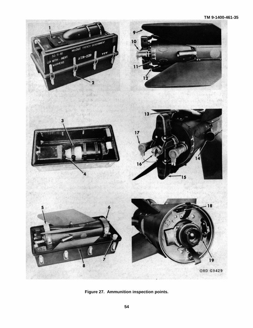
TM 9-1400-461-35
Figure 27. Ammunition inspection points.
54

TM 9-1400-461-35
(2) Segregate containers which showevidence of tough handling: remove themissiles as outlined in paragraph 44. Ifthey are found to be serviceable, replacethem in the shipping containers and placethe shipping containers in storage.
(3) If the missile containers are fount to beunserviceable, segregate them and makea report in accordance with paragraph 50.
(4) In the case of missiles returned by theuser, inspect each missile as outlined inparagraphs 44 and 47. This must be donewithin 30 days after the missiles arereceived.
b. Annual.(1) When a ot of missiles has been in storage
1 year, select a sample of the lot atrandom. See table 7 for size of thesample.
(2) Inspect the missiles selected as outlinedin paragraphs 44 and 47.
c. Preshipment. Inspect as required in b aboveunless the lot has been inspected in the last eightmonths and found serviceable, no inspection isnecessary.
d. Special inspection. The U.S. Army Missilecommand may require inspection of the missiles otherthan those inspections indicated in a, b, and c above.44. Visual Inspection (fig. 27)
Note:Defects printed in bold face type areconsidered to be major defects. Ifany of these defects are foundduring inspection of first sample,inspect a second sample for thesedefects. Refer to table 4 for size ofthe second sample. If these defectsare found in the second sample,inspect the entire lot.
a. Shipping Containers.(1) Proper color coding and painting (table 8).(2) Breaks, splits and holes.(3) Presence and serviceability of latches and
pins (2, fig. 28).(4) Condition and presence of battery holder,
cover, clamp key and attaching hardware(1).
(5) Container seal (8) for properinstallation, deterioration or breaks.
(6) Presence and condition of cartridgeholder (7) in base of container.
(7) Proper operation and condition offorward (6) and aft clamp (5)assemblies which secure the missile inbase of container.
(8) Missing or damaged straps (3) thatsecure the warhead in top of container.
(9) Presence and proper installation ofwarhead cushioning material (4) in topof container.
Warning:Always inspect the warhead armingdevice immediately before removingthe missile body from the shippingcontainer. If it is armed call ademolition specialist to dispose ofthe missile.
b. Missiles.(1) Inspect the condition of the warhead
arming device. The top of the armingpiston should not protrude above thesurface of the rim (fig. 28).
(2) Proper color coding and marking (table 5).(3) Dents or breaks on the skin.
Table 7. Inspection-Sample SizesInspection-sample
sizeLot size Accumulative sample size
First sample Second Sample0-8 3 Balance of lot 8
9-15 3 Balance of lot 1516-25 5 Balance of lot 2526-40 5 10 1541-65 7 14 21
66-110 10 20 30111-180 15 20 30181-300 25 50 75301-500 35 70 105501-800 50 100 150
801-1300 75 150 225
55

C3, TM 9-1400-461-35
Table 8. Ammunition Color Coding
MarkingsNomenclature Basic Color Warhead tip Basic Marking Corner ICC Markings on containers
Missile Warhead Missile Warhead nose color Color only
Guided Missile OD OD Yellow Yellow Yellow OD Yellow Yellow ROCKET AMMUNITIONAGM 22B WITH EXPLOSIVE
PROJECTILEGuided Missile OD OD White White Blue OD White Blue ROCKET AMMUNITION
ATM 22B WITH INERTPROJECTILE
Missile, SS 11 Blue Blue White White None OD White None Nonecompletely inert.
Note 1. Live motors will have four 2-inch brown squares 90 degrees apart.Note 2. Container corner markings will be diagonally opposite.
(4) Presence of rust, corrosion ormoisture.
(5) Loose or damaged fins (9, fig. 28).(6) Loose or distorted rear cover (11).(7) Damaged, loose or corroded electrical
contacts (18).(8) Missing or damaged junction box (15).(9) Damaged or missing hook (10) (J-box
release).(10) Broken or missing flares (17).(11) Missing or deteriorated sleeving on
guidance wires (12).(12) Damaged or missing retainer springs
(J-box).(13) Breaks or kinks in exposed guidance
wires.(14) Broken or deteriorated wiring.(15) Broken or clogged exhaust ports (14).
Figure 28. Warhead arming device.
(16) Missing or damaged attachinghardware.
(17) Breaks or dents on spool housing (13).(18) Missing or damaged support ring.(19) Bent or broken pins or corrosion on
electrical plug (16).(20) Missing or damaged fuze protector
plug (19).(21) Nicks, burrs, rust or corrosion on fuze
threads.(22) Improper mating of missile to warhead.
c. Warheads(1) Proper marking and painting (table 5).(2) Presence of dents or breaks.(3) Corrosion or oxidation on the skin.(4) Evidence of rust or corrosion on
internal threads.(5) Damaged, loose or missing screws
which secure the two sectionstogether.
d. Explosive Cartridge.Note.
Normally the explosive cartridge isshipped in the shipping containersof the missile. It must be visuallyinspected for serviceability.
(1) Proper identification(2) Damaged or improper packaging.(3) Evidence of rust or corrosion.
e. Explosive Bolt.(1) Serviceability and installation of
shorting plug.(2) Proper identification.(3) Damaged or improper packaging.(4) Presence of dents, rust or corrosion.
66

C1, TM 9-1400-461-35
f. Batteries.Note.
The batteries are shipped in separatecontainers.
(1) Presence of dents or breaks on casing,which would render the batteries unserviceable.
(2) Bent, broken, or corroded electricalconnections.
(3) Serviceability and presence of adhesivetape and microcrystalline wax.
(4) Proper labeling to insure shelf lifelimitations are not exceeded.
Section III. ELECTRICAL TESTING45. GeneralThese tests involve handling and electrical testing ofammunition items. The live missile body and the HEATwarhead contain explosives and must be handled withcare. Although the missile tester is designed to safety-check the internal circuitry of the missile, it is imperativethat all possible safety precautions be observed. Sincethe possibilities of accidental motor ignitions cannot beoverlooked, the selection of the site for electrical testingis of prime importance.46. Test Area RequirementsElectrical testing of the missile may be conducted ineither a specifically designated building or outside in theopen. In either case, the test area must meet theminimum safety requirements specified in TM 9-1300-206 (overseas) or AMCR 385-224 (CONUS) and allapplicable standing operating procedures (SOP's).
Warning:The missile with live motor andwarhead is in quantity-distance class7; the missile with live motor andinert warhead is in quantity-distanceclass 5. All inspections should be inaccordance with applicable quantity-distance tables and safetyinstructions contained in TM 9-1300-206 and AMCR 385-224.
46.1. Sample Sizes for Electrical and ContinuityTesting
a. Unless otherwise noted, the lot sample size forelectrical and continuity tests of the missile, explosivebolts, and explosive cartridges will be as specified intable 7.
b. If during tests of the first sample, 15 percent ofthe sample fails to pass, a second sample will beselected in accordance with table 7. If, after testing thesecond sample, 25 percent of the total tested fail the
test, the complete lot will be tested, and the resultsreported in accordance with TM 38750.47. Electrical Check of the Missile
a. Missile test set M22 Set D (FSN 4935-953-9962), composed of the following components, is usedto perform electrical check of the missile:
(1) Rocket circuit continuity tester (fig. 29),Model 101-5BFG (Alinco) 4925-712-0205.
(2) Maintenance and inspection holddownfixtures ORDXM-SMD-1939.
(3) Continuity test cable assembly (fig. 29)(SS-11B) ORDXR-FMO-1703.
b. Set up the equipment as follows:(1) Set the holddown fixture on a level
surface behind a suitable barricade.(2) Place four sand bags on the base of the
holddown fixture.(3) Loosen the two missile-holding screws on
the holddown fixture.Warning:
Always inspect the warhead armingdevice immediately before removingthe missile body from the shippingcontainer. If it is armed, call ademolition specialist to dispose ofthe missile.
(4) Remove the missile body section from theshipping and storage container.
(5) Place the missile body in the holddownfixture as shown in figure 30. Make certain the holdingscrews engage in the missile-locking slots.
(6) Remove the missile container with theHEAT warhead from the checkout area, and place itbehind a suitable barricade.
(7) Drive the ground stake into the groundand connect the cable between the stake and theholddown fixture.
AGO 6287A
57

C1, TM 9-1400-461-35
Figure 29. Alinco continuity test, Model 101-5BFG and cable.
c. Check the resistance of the test cable asfollows:
(1) Connect the 2-pin connector on the testcable assembly to the receptacle on top of the continuitytester.
(2) Connect a shorting wire between pins 3and 5 of the 7-pin plug on the test cable.
(3) Set the switch on the test cable to position1.
Note.Make certain the OHMS ADD switchon the continuity tester is set to the 0position.
(4) Press and hold the KEY switch on thecontinuity tester.
(5) Operate the OHMS knob on the testeruntil the balance meter indicates zero (center scale).
(6) Release the KEY switch and record theresistance as indicated by the OHMS counter. Recordalso the position of the test cable switch.
(7) Repeat steps 4, 5, and 6 with the
AGO 6287A
58

C1, TM 9-1400-461-35
shorting wire connected between pins 5 and 6 and theswitch set to position 2.
(8) Repeat steps 4, 5, and 6 with the shortingwire connected between pins 5 and 7 and the switch setto position 3.
(9) Repeat steps 4, 5, and 6 with the shortingwire connected between pins 4 and 5 and the switch setto position 4.
(10) Remove the shorting wire, set the switchto the OFF position, and disconnect the test cable fromcontinuity tester.
Warning:Operator making cable connectionsto the missile should wear safetyglasses or goggles.
d. Lay out the test cable and connect it to the 7-pinconnector on the rear of the missile junction box.
Warning:Make certain the electrical-checkoutarea is clear. Everyone must bebehind the barricade.
e. Make certain the switch on the test cable is setto the OFF position. Connect the test cable to thecontinuity tester.
AGO 6287A
58.1

C1, TM 9-1400-461-35
Figure 30. Missile in hold down fixture.f. Check the resistance of the missile ignition
circuits as follows:(1) Set the switch on the test cable to position
1.(2) Press and hold the KEY switch on the
continuity tester.(3) Operate the OHMS knob until the balance
meter indicates zero (center position)(4) Release the KEY switch and record the
resistance as indicated on the OHMScounter. Record also the position of thetest cable switch.
Note.This reading includes the resistanceof the ignition circuits plus the cable.
(5) Repeat steps 2, 3, and 4 for each positionof the switch on the test cable.
g. Disconnect the test cable from the continuitytester.
h. Compute the actual resistance of the missileignition circuits using the following formula: Resistanceof cable and ignition circuits (recorded in e above)minus resistance of cable (recorded in b above) equalsactual resistance of missile ignition circuits.
Note.The resistance of the ignition circuitsmust be within specified tolerances.
i. Compare the computed resistance of the missileignition circuits with the tolerances listed in table 9.
j. Disconnect test cable and remove the missilebody from the hold-down fixture.
k. Repack the missile body in the shippingcontainer from which it was removed.
Warning:Missiles which are found to beunserviceable shall not be storedwith serviceable missiles. Clearlymark the containers of unserviceablemissiles so that they will be storedseparately.
l. Perform the continuity check of the explosivecartridge (packed in the shipping container) as outlinedin paragraph 48.
Note.Results of the missile electricalchecks are to be reported asspecified in paragraph 46.1 and 50.
Warning:Only one explosive cartridge will beallowed in the test area at a time.Only the operator will be in theimmediate area while the test isbeing conducted.
Table 9. Missile ignition Circuits-Resistance Tolerances
Position of test Minimum allowable Maximum allowablecable switch resistance resistance
1 2.5 ohms 5.5 ohms2 19.5 ohms 26.5 ohms3 1.60 ohms 2.40 ohms4 3.00 ohms 4.00 ohms
59

C1, TM 9-1400-461-35
48. Continuity Check of Explosives CartridgeFSN 1337-956/2732
a. The following equipment is required to performthe continuity check:
(1) Rocket circuitry tester, Model 101-5BFG(Alinco) 4929-712-0205.
(2) Test lead (fig. 31).b. Remove the explosive cartridge from the
missile shipping container.
Warning:Explosive cartridges are in quantity-distance class 1 and compatibilitygroup E.
c. Place the explosive cartridge in the test area sothat the ends of the cartridge are pointing away from theoperator's test position.
Warning:Safety glasses or goggles will beworn by the operator making testlead connections and he must havethe test leads in his possession at alltimes.
Figure 31. Explosive cartridge test lead.
AGO 6287A
60
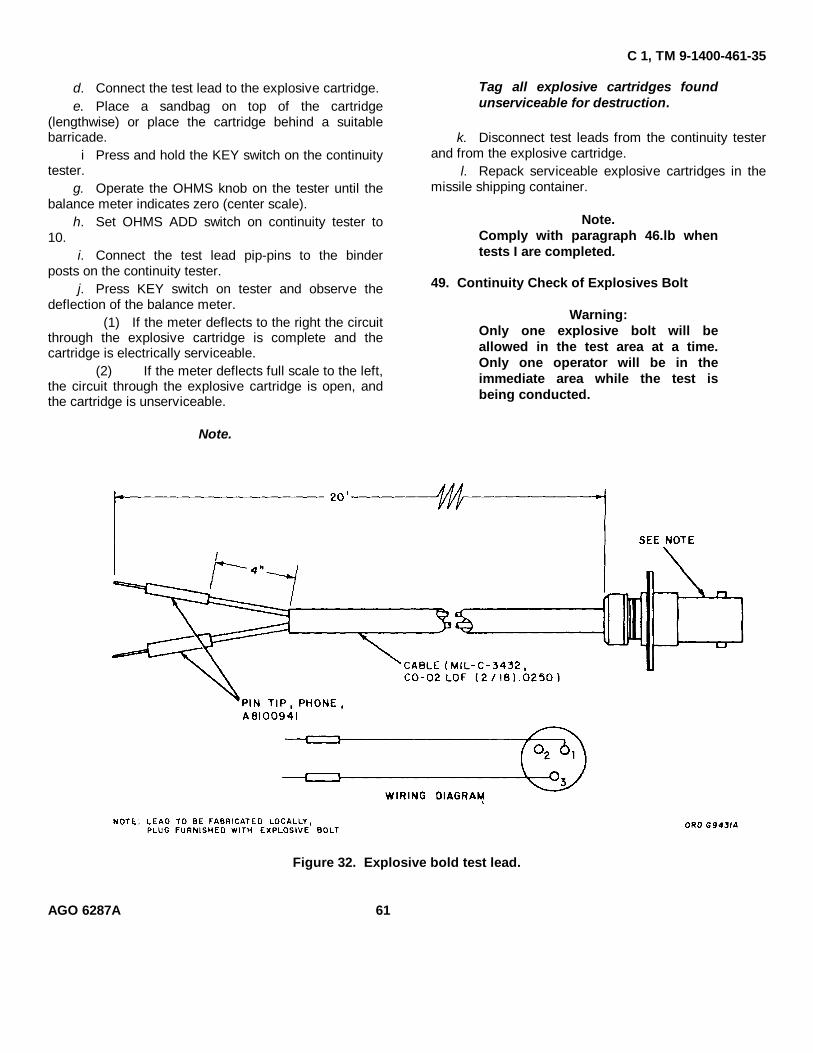
C 1, TM 9-1400-461-35
d. Connect the test lead to the explosive cartridge.e. Place a sandbag on top of the cartridge
(lengthwise) or place the cartridge behind a suitablebarricade.
i Press and hold the KEY switch on the continuitytester.
g. Operate the OHMS knob on the tester until thebalance meter indicates zero (center scale).
h. Set OHMS ADD switch on continuity tester to10.
i. Connect the test lead pip-pins to the binderposts on the continuity tester.
j. Press KEY switch on tester and observe thedeflection of the balance meter.
(1) If the meter deflects to the right the circuitthrough the explosive cartridge is complete and thecartridge is electrically serviceable.
(2) If the meter deflects full scale to the left,the circuit through the explosive cartridge is open, andthe cartridge is unserviceable.
Note.
Tag all explosive cartridges foundunserviceable for destruction.
k. Disconnect test leads from the continuity testerand from the explosive cartridge.
l. Repack serviceable explosive cartridges in themissile shipping container.
Note.Comply with paragraph 46.lb whentests I are completed.
49. Continuity Check of Explosives Bolt
Warning:Only one explosive bolt will beallowed in the test area at a time.Only one operator will be in theimmediate area while the test isbeing conducted.
Figure 32. Explosive bold test lead.
AGO 6287A 61

C 1, TM 9-1400-461-35a. The following equipment is required to perform
the continuity check:(1) Rocket circuitry testing, Model 1015BFG
(Alinco) 4925-712-0205.(2) Test lead (fig. 32).
b. Turn galvonometer needle adjust screw onAlinco tester clockwise until needle is centered onmidscale graduation of meter.
c. Set digital dial (using OHMS control knob) andOHMS ADD switch on zero.
d. Connect pin-tips of test lead to binder posts oftester, and short loose end of test lead.
e. Depress test key, and rotate OHMS control knobuntil galvanometer needle is centered on midscalegraduation of meter.
f. Read and record resistance shown on digitaldial.
g. Disconnect test lead from binder post on tester.h. Place explosive bolt behind a suitable barricade,
and place a sandbag over it.i. Remove shorting plug from explosive bolt cable,
and connect test lead.j. Connect test lead to binder post on tester.
k. Depress test key on tester, and rotate OHMScontrol knob until galvanometer needle is centered onmidscale graduation of meter.
l. Read and record resistance shown on digitaldial.
m. Subtract resistance obtained in f above fromresistance obtained in l above. Resistance should bebetween 1.5 and 2.5.
Note:Tag all explosive bolts foundunserviceable for destruction.
n. Disconnect test lead, and replace explosive-boltshorting plugs.
o. Remove explosive bolt from barricade, andreturn to storage.
Note.Comply with paragraph 46.1b whentests are completed.
49.1. Function Test of Explosives Bolta. Test Requirements. Three years after the date
of manufacture, a function test will be performed (bydepot personnel) on a sample of each lot of explosive
bolts in storage. The purpose of the function tests is todetermine whether the shelf life of the bolts may beextended for an additional 3 years. Six years will be themaximum shelf life for these bolts; therefore, functiontesting will be once only for each lot.
b. Equipment Required. The following equipmentis required to perform the function test:
(1) Cabinet, test, subzero, working chamber,American Instrument Mfg. Co., Tag TSA C310 (59-41),or equal.
(2) Barricade (ORDXR-FMO-918), or equal.(3) Holding fixture (SMM-MAP-298) (fig.
32.1).(4) Tester, Alinco, Model 102-5BFG, with test
leads.(5) Firing leads (twisted pair) A.W.G. 18.(6) Protective clothing and equipment.(7) Gloves, asbestos and leather.(8) Safety goggles, FSN 4270-269-7911.(9) Power supply, regulated, Model QCR
36/85, Utronics, Inc., Clinton, N. Y., or equal.c. Safety Precautions. Observe the following
safety precautions when performing the function test:(1) Operators must wear flame-proof outer
clothing and sparkproof safety shoes.(2) Personnel will be kept to a minimum for a
safe and efficient operation.(3) Explosive quantity distance class 3 and
compatibility group F will be observed when handlingexplosive bolts.
(4) Safety glasses must be worn whenhandling explosive bolts.
(5) Operation will be suspended whenelectrical storms are imminent.
d. Sample Selection. Use table 7 as a guide inchoosing the sample. The quantity of bolts chosen,however, should be evenly divisible by three, becausethere are three different function tests to be performed(para f, g, and h below).
e. Continuity Test. Perform the followingcontinuity test on the explosive bolts before functiontesting:
(1) Remove one bolt from its storagecontainer; unpack and place it in the approvedbarricade.
AGO 6287A 62

C 1, TM 9-1400-461-35
Warning:Immediately after bolt has beenunpacked, check for presence ofshorting plug and any obviousdefects or damage before continuingthis operation.
(2) Extend the cable lead end with shortingplug through the hole in the barricade, and close thebarricade door.
(3) Check and record the resistance of thetest cable.
(4) Remove the shorting plug from theexplosive bolt lead cable.
Caution:The complete test lead cable must bein the possession of the operatormaking the electrical connection.
(5) Connect the test lead provided with ashorting plug to the explosive-bolt harness.
(6) Extend the test lead cable (away) fromthe barricade to the Alinco tester.
(7) Using OHMS control knob, set digital dialand OHMS ADD switch at zero.
(8) Remove the shorting plug from the testlead cable, and connect it to the Alinco tester.
(9) Depress the test key, and rotate theOHMS control knob until the galvanometer needle iscentered at midscale graduation of the meter.
(10) Read and record resistance on digital dial.(11) Subtract the resistance obtained in (3)
from that obtained in (10).Note.
Acceptable resistance of explosivebolts is 1.5 to 2.5 ohms.
(12) Disconnect the test lead cable from theexplosive bolt.
(13) Replace the shorting plug to the explosivebolt harness.
(14) Open the barricade door, and remove theexplosive bolt.
(15) Repack and place the explosive bolt inapproved temporary storage until needed for one of thefollowing tests (para f, g, or h below).
(16) Repeat (1) through (15) above until thequantity of bolts chosen for function testing (d above)have been accumulated. If any bolts fail the continuitytests, apply the requirements in paragraph 46.1b.
Note.Tag all unserviceable explosive boltsfor destruction.
f. Waterproof Function Test.
Note.The waterproof function test will beconducted on I/3 of the explosivebolts selected for test (d above).
(1) Remove one explosive bolt fromapproved temporary storage (e(15) above), and unpack.
(2) Remove the self-locking nut from theexplosive bolt.
(3) Submerge the explosive bolt in acontainer of water for 30 minutes inside a temperaturecontrolled chamber preconditioned to 200 ± 5" C.
Caution:Do not submerge the connector andshorting plug.
(4) Remove the bolt from the chamber.(5) Connect the bolt to the holding fixture
SMM-MAP-298 (fig. 32.1) by placing the threaded screwthrough the 11/17-inch hole and securing it with thebackup plate and two screws MS35307-64.
(6) Place the holding fixture with explosivebolt inside the barricade.
(7) Extend the connector and shorting plugthrough the small opening in the barricade.
(8) Close the barricade door.(9) Remove the shorting plug from connector
on the explosive bolt, and connect the firing lead cable.Caution:
The firing lead or the power sourceactuating device must be in thepossession of the operator makingthe electrical connection.
(10) Extend the firing lead cable from thebarricade to the power source.
(11) Prior to making the connection to thepower source, the firing circuit will be tested with agalvanometer for electrical continuity.
Note.The normal operating current fordetonating the explosive bolt is oneamp for a period of 1/10 second.
(12) Fire the explosive bolt by using a 24vdcpower source equipped with a voltage and amperagecontrol device.
AGO 6287A 62.1

C 1, TM 9-1400-461-35
Figure 32-1. Holding fixture.
Caution:If a misfire occurs, four successiveattempts should be madeimmediately to fire the explosivebolts. If these attempts fail, theconnections of the firing wires to thepower source should be checked;then, three more attempts to fire theexplosive bolts should be made. Ifthe explosive bolt still fails to fire,disconnect the firing wires from thepower source; short the ends of thefiring wires together; and wait 30minutes before investigating thecause of the misfire. Misfired boltswill be taken to the demolition areafor destruction.
13) Open the barricade, and remove theholding fixture with fired bolt.
(14) Remove the explosive bolt metal parts,and dispose of them.
(15) Repeat (1) through (14) until all bolts inthe waterproof sample have been subjected to thefunction test.
g. Low-Temperature Function.
Note.The low temperature test will beconducted on 1/3 of the explosivebolts selected for test in d above.
(1) Remove one of the explosive bolts fromtemporary storage, and unpack.
AGO 6287A 62.2

C 1, TM 9-1400-461-35
(2) Remove the self-locking nut from theexplosive bolt.
(3) Connect the bolt to the holding fixtureSMM-MAP-298 by placing the threaded screw throughthe 11/16-inch hole and securing it with the lockup plateand two screws MS35307-64.
(4) Precondition the temperature controlledchamber to -50° C., and place the bolt inside for aperiod of 1 hour.
(5) Wearing leather gloves, remove theexplosive bolt and the holding fixture from thetemperature controlled chamber, and place in anapproved barricade.
(6) To fire the bolt, follow (7) through (14) of fabove.
(7) Repeat the above procedure until all boltsselected for the low-temperature test have beensubjected to the function test.
h. High-Temperature-Function Test.Note.
The high-temperature function testwill be conducted on ½ of theexplosive bolts selected for test in dabove.
(1) Remove one of the explosive bolts fromtemporary storage, and unpack.
(2) Remove the self-locking nut from theexplosive bolt.
(3) Connect the bolt to the holding fixture byplacing the threaded screw through the 11/16-inch holeand securing it with the lockup plate and two screwsMS35307-64.
(4) Place the explosive bolt for one hourinside the temperature-controlled chamber, which hasbeen preconditioned to +80° C.
(5) Using the asbestos gloves, remove theexplosive bolt and holding fixture from the temperature-controlled chamber, and place in an approved barricade.
(6) To fire the explosive bolt, follow (7)through (14) of f above.
(7) Repeat the above procedure until all boltsselected for the high temperature function test havebeen subjected to the test.
i. After-Test Procedures. According to the testresults, comply with (1) or (2) below.
(1) If 100 percent of the explosive boltsfunctioned properly, the shelf life of the lot may beextended to 6 years from the date of manufacture.Update all ammunition records to indicate the new shelflife expiration date. Report the lot number, the samplesize used for function testing, and the new shelf lifeexpiration date to Commanding General, U.S. ArmyMissile Command, ATTN: AMSMI-SMMDA, RedstoneArsenal, Ala. 35809.
(2) If less than 100 percent of the explosivebolts failed to function, report the complete results of thetest in accordance with TM 38-750.50. Reports and Disposition Instructions
a. Report unserviceable missiles to CommandingGeneral, U.S. Army Missile Command, ATTN: AMSMI-SMMDA, Redstone Arsenal, Ala. 35809, on DA Form2415 (Ammunition Condition Report) in accordance withTM 38-750. Include the following:
(1) Nomenclature.(2) Federal stock number.(3) Lot and serial numbers.(4) Quantity received.(5) Shipping order number.(6) Date received.(7) Unsatisfactory condition encountered.(8) Statement as to feasibility of local
corrections.(9) Quantity of missile on hand.
(10) Quantity of unserviceable missiles.b. Dispose of unserviceable missiles in
accordance with chapter 7.
AGO 6287A 62.3

TM 9-1400-461-35C 6
CHAPTER 7SHIPMENT, STORAGE, STATIC FIRING, AND DETONATION
Section I. SHIPMENT AND STORAGE
51. GeneralThis section pertains to shipment and storage of themissile and other system explosive items. Commandersare responsible for insuring that all materiel issued orassigned to their commands is maintained in aserviceable condition and properly cared for, and thatpersonnel under their command comply with technicalinstructions.
52. ShipmentPreservation and other protective measures taken in thepreparation of the materiel for shipment should besufficient to protect it against deterioration and physicaldamage during shipment.
53. Storage Precautionsa. Ammunition items should be stored separately
from nonexplosive items.b. The ammunition items should be stored only in
magazines or igloos specifically designated forammunition storage. When specially constructedmagazines are not available, the building used shouldbe sufficiently ventilated and afford adequate protectionagainst moisture and dampness.
c. Outside storage may be used only when suitablebuildings are not available. The methods used shouldprovide adequate circulation of air and good protectionagainst moisture. Materiel should be covered withpaulins or other suitable covering. The cover shouldallow free circulation of air about the containers.Suitable trenches should be dug to prevent water fromrunning under the stacks during inclement weather.
d. The storage temperature limits of minus 300 topositive 500 Centigrade should not exceed 6 hours forany one period.
NOTEFor correct quantity-distance classifi-cation and compatibility groupings,see table 10.
e. The missile and explosive cartridge have anindefinite shelf life.
f. Disregard the expiration date marked on thebattery case, and consider the shelf-life to be 14 monthsfrom the date of manufacture, also stamped on thebattery case. Batteries may be used for an additional 6months (20 months total) for training purposes inCONUS.
Table 10. Quantity-Distance Classification andCompatibility Grouping
Component Quantity-distance Compatibilityclass group step
Complete roundwith explosivewarhead
............7 .........F
Complete roundwith inert warhead.
............5 .........F
Explosive warheadonly
............7 .........F
Explosive bolt ............3 .........BExplosivecartridge
............1 .........E
Section II. STATIC FIRING AND DETONATION
54. GeneralThis section covers static firing and detonation ofunserviceable ammunition components of the M22subsystem.
55. Static Firing of MissileStatic firing of unserviceable missiles should beaccomplished in accordance with table 11.
63

TM 9-1400-461-35C 2
Table 11: Static Firing of Missile
Equipment required:a. Protective clothing.b. Holding fixture, FSN 5935-991-6674.
Note.Before static firing, make sure that a 1/2 inch by 1 inch slot has been cut in the holding fixturesleeve (in the base) so the blasting cap can be inserted.
c. Demolition cable SMM-MAP 267, figure 38.d. Blasting cap, number 8 FSN 1475-0285215.e. Blasting galvanometer, FSN 6625-212-4605.f. Detect-a-meter, FSN 6625-356-0295.g. Masking tape, FSN 7510-266-710.h. Safety glasses, FSN 4240-276-7343.i. Electrical tape, FSN 5970644-3169.
Step Operation
1 Place holding fixture (fig. 30) on level ground, 300 feet from barricade.2 Place sand bag (approx 50 lbs) on each corner of holding fixture plate.3 Lay demolition cable SMM-MAP 267 from barricade holding fixture at destruction site.4 Lay another demolition cable (less electrical connector) from barricade to destruction site.5 Twist ends of demolition cables together at barricade and connect to ground.6 Transport missile to destruction site.7 Remove missile from shipping and storage container and place in holding fixture with forward end down.8 Transport container and warhead from destruction area to a sale location.9 Secure missile in holding fixture with screws provided with fixture.
10 Using a detect-a-meter, check demolition cable for stray current.11 Clear area of all personnel except two operators.12 Remove the protective cover on the electrical connector on the aft end of missile.13 Connect demolition cable to missile.
Note:.One operator will make electrical connections at missile whilethe second operator observes from outside the barricade
14 Untwist ends of blasting cap leads and connect to demolition cable (step 4).15 Place the explosive end of the blasting cap in the cutout of the holding fixture sleeve and secure with tape.16 Retire to barricade.17 Disconnect missile demolition cable from ground and untwist ends of wires.18 Touch ends of demolition cable to blasting galvanometer. If needle shows a deflection, connect to
power source of at least 28 vdc and fire the motor.19 Disconnect warhead detonator demolition cable from ground and untwist ends of wires.20 Touch ends of warhead detonator demolition cable to blasting galvanometer. If needle shows a deflection.
unlock blasting machine cabinet and remove the blasting machine.21 Connect demolition cable to blasting machine.22 Raise handle of blasting machine and push down rapidly.23 After motor and warhead detonator have fired, disconnect demolition cable at power source
64

TM 9-1400-461-35Table 11. Static Firing of Missile-Continued.
Step Operation
24. Using flashlight, check to determine if a clean burnout was obtained during firing and the blasting cap hasdetonated.
Note.If motor propellant fails to ignite or a clean burnout is notaccomplished, destroy missile body as outlined in table 12.
25. Remove the missile body from holding fixture and transport to demolition burning pit for further disposal.26. After burning missile body, remove inert metal scrap and transport to property disposal.
56. Detonating MissileWhen static firing of unserviceable missilescannot be accomplished the missile should bedestroyed by detonation in accordance withtable 12.
57. Detonation of WarheadDetonation of unserviceable warheads shouldbe accomplished in accordance with table 13.
Table 12. Detonation of MissilesEquipment required:
a. Blasting cap no. 8, FSN 1375-028-5215.Note. Blasting cap should be tested for continuity before being transported to destruction site.
b. Blasting galvanometer, FSN 6625-212-4605.c. Detect-A-Meter, FSN 6625-356-0295.d. Detonating cord no. 100, FCN 1375-078-5164.e. Firing wires, FSN 6145-188-3657.f. Masking tape, FSN 7510-266-6710.g. Plastic explosives (composition C4), FSN 1375-028-5148.h. Protective clothing.i. Safety glasses, FSN 4240-2767343.
Step Operation
1 Lay two firing wires from barricade to destruction site. Destruction site should not be less than 300 feet from thebarricade.
2 Twist ends of firing wires together and connect to ground at barricade.3 Transport the missile to the destruction site.4 Remove the missile body from the shipping and storage container.5 Place the missile body on the ground.6 Transport the container and warhead away from operation area to a safe location.7 Tie a single knot at one end of a 24-inch detonating cord and mold two ounces of composition C4 explosives over
knot. Explosives should cover approximately 3 inches of cord and be evenly distributed8 Place the explosives end of detonating cord approximately 8 inches from the forward end of missile body on top of
motor and secure in place with masking tape.9 Position the detonating cord over warhead detonator and secure in place with masking tape.
10 Using a detect-a-meter, check firing wires for stray current.11 Clear area of all personnel except two operators. One operator will make electrical connections at missile while the
second operator observes from outside the barricade12 Untwist blasting cap lead wires and connect to firing wires.13 Tape blasting cap to end of detonation cord and retire to barricade.
65

TM 9-1400-461-35
Table 12. Detonation of Missile--Continued.
Step Operation
14 Disconnect firing wires at ground and untwist ends of wires.15 Touch ends of firing wires to blasting galvanometer. If needle shows a deflection, unlock blasting machine cabinet,
remove blasting machine and connect firing wires to blasting machine16 Raise handle of blasting machine and push down rapidly. Flares will probably fail to ignite during detonation but will
ignite when placed in demolition burning pit.17 After detonation, disconnect firing wires at power source.18 Transport metal scrap to demolition burning pit for further disposal. Insure that all fire is extinguished before
transporting scrap to burning pit
66

TM 9-1400-461-35Table 13. Detonation of Warhead
Equipment required:a. Blasting cap no. 8, FSN 1375-028-5215.
Note. Blasting cap should be tested for continuity before being transported to destruction site.b. Blasting galvanometer, FSN 6675-212-5625.c. Detect-A-Meter, FSN 6625-356-0295.d. Detonating cord No. 100, FSN 1375-078-5164.e. Firing wires, FSN 6145-188-3657.f. Masking tape, FSN 7510-266-6710.g. Plastic explosive (composition C4), FSN 1375-028-5148.h. Protective clothing.i. Safety glasses, FSN 4240-276-7343.
Step Operation
1 Dig a pit or trench approximately four feet deep 300 feet from barricade.2 Lay two firing wires from barricade to destruction site.3 Twist ends of firing wires together and connect to ground at barricade.4 Transport warhead to destruction site.5 Remove the warhead from the shipping and storage container and place in the pit with forward and down.6 Transport warhead container from destruction area to a safe place.7 Tie a double knot in detonating cord (54 inches long) approximately six inches from one end and mold
one-half pound of composition C4 explosives around the knot.8 Place the explosive near the center of aft end of warhead and secure in place with masking tape.9 Cover the warhead with at least two feet of earth.
10 Using a detect-a-meter, check firing wires for stray current.11 Clear area of all personnel except two operators. One operator will make electrical connections at destruction
sight while the second operator observes from the barricade.12 Untwist ends of blasting cap lead wires and connect to firing wires.13 Tape blasting cap to detonating cord and retire to barricade.14 Disconnect firing wires at ground and untwist ends.15 Touch ends of wires to blasting galvanometer. If needle shows a deflection, unlock blasting machine cabinet and
remove the blasting machine.16 Connect firing wires to blasting machine.17 Raise handle of blasting machine and push down rapidly.18 After detonation, disconnect firing wires at power source and connect to ground.
67

TM 9-1400-461-35
Figure 33. Loading and bracing in closed or open top van trailer, (sheet 1 of 6).
68

TM 9-1400-461-35
Figure 33. Loading and bracing in closed or open top van trailer, (sheet 2 of 6).
69

TM 9-1400-461-35
Figure 33. Loading and bracing in closed or open top van trailer, (sheet 3 of 6).
70

TM 9-1400-461-35
Figure 33. Loading and bracing in closed or open top van trailer, (sheet 4 of 6).
71

TM 9-1400-461-35
Figure 33. Loading and bracing in closed or open top van trailer, (sheet 5 of 6).
72

TM 9-1400-461-35
Figure 33. Loading and bracing in closed or open top van trailer, (sheet 6 of 6).
73
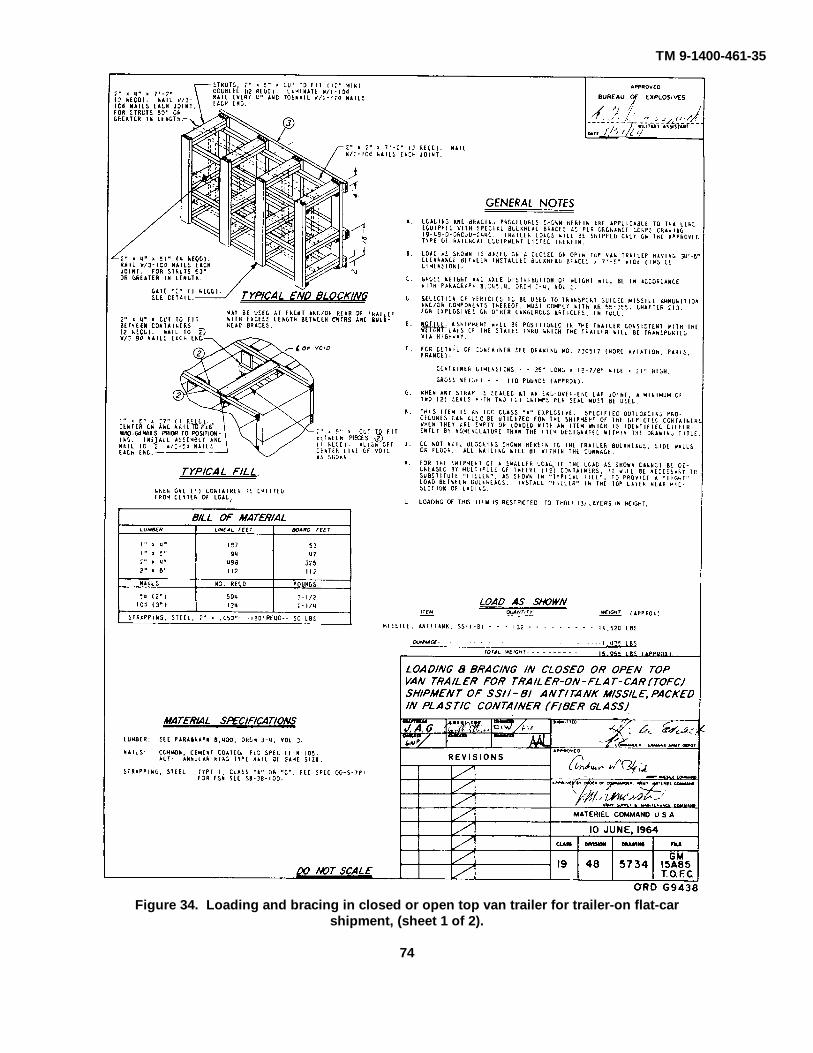
TM 9-1400-461-35
Figure 34. Loading and bracing in closed or open top van trailer for trailer-on flat-carshipment, (sheet 1 of 2).
74

TM 9-1400-461-35
Figure 34. Loading and bracing in closed or open top van trailer for trailer-on flat-carshipment, (sheet 2 of 2).
75

TM 9-1400-461-35
Figure 33. Loading and bracing in box cars, (sheet 1 of 8).
76

TM 9-1400-461-35
Figure 35. Loading and bracing in box cars, (sheet 2 of 8).
77

TM 9-1400-461-35
Figure 35. Loading and bracing in box cars, (sheet 3 of 8).
78

TM 9-1400-461-35
Figure 35. Loading and bracing in box cars, (sheet 4 of 8).
79

TM 9-1400-461-35
Figure 35. Loading and bracing in box cars, (sheet 5 of 8).
80

TM 9-1400-461-35
Figure 35. Loading and bracing in box cars, (sheet 6 of 8).
81

TM 9-1400-461-35
Figure 35. Loading and bracing in box cars, (sheet 7 of 8).
82

TM 9-1400-461-35
Figure 35. Loading and bracing in box cars, (sheet 8 of 8).
83

C1, TM 9-1400-461-35
Figure 36. Storage in 60- and 80-foot igloo magazines (sheet 1 of 2).
84

C1, TM 9-1400-461-35
Figure 36. Storage in 60- and 80-foot igloo magazines (sheet 2 of 2).
85

TM 9-1400-461-35
Figure 37. Loading and bracing in DF type box cars, (sheet 1 of 7).
86

TM 9-1400-461-35
Figure 37. Loading and bracing in DF type ox cars, (sheet 2 of 7).
87

TM 9-1400461-35
Figure 37. Loading and bracing in DF type box cars, (sheet 3 of 7).
88

TM 9-1400-461-35
Figure 37. Loading and bracing in DF type box cars, (sheet 4 of 7).
89

TM 9-1400-461-35
Figure 37. Loading and bracing in DF type box cars, (sheet 5 of 7).
90

TM 9-1400-461-35
Figure 37. Loading and bracing in DF type box cars, (sheet 6 of 7).
91

TM 9-1400-461-35
Figure 37. Loading and bracing in DF type box cars, (sheet 7 of 7).
92
TM 9-1400-461-35
Figure 38. Demolition cable.
92.1

TM 9-1400-461-35
REFERENCES
1. Publications Indexes
Consult the following indexes frequently for latest changes or revisions of references given in this appendix andfor new publications relating to materiel covered in this technical manual.
Military Publications:
Index of Blank Forms .......................................................................................................... DA Pam 310-2Index of Tables of Organization and Equipment, Tables of Organization,
Type Tables of Distribution, and Tables of Allowances............................................... DA Pam 310-7Index of Technical Manuals, Technical Bulletins, Supply Bulletins, Lubrication
Orders, and Modification Work Orders....................................................................... DA Pam 310-4Index of Supply Manuals, Ordnance Corps ................................................................... DA Pam 310-29
2. Related Technical Manuals
Operator, Organizational, Direct Support, General Support, and Depot MaintenanceManual: Truck-Mounted Maintenance Equipment (Guided Missile Helicopter-Armament Subsystem M22).......................................................................................... TM9-4935-461-15/1
Operator's and Crew Member's Manual, Army Models UH-IA & UH-1BHelicopters.................................................................................................................... TM 55-1520-211-10
3. Supply Manuals
The following manuals o the Department of the Army Supply Manual pertain to this materiel:
a. General.Introduction ......................................................................................................................... ORD 1Ordnance Major Items and Major Combinations and Pertinent Publications ....................... SB 9-1Requisitioning of Repair Parts and Assemblies Added by ModificationWork Orders ....................................................................................................................... SB 9-150
b. Inspection and Repair.Command Maintenance Inspection ..................................................................................... AR 750-8Crystal Rectifiers................................................................................................................. TB SIG 162Electrical Wiring.................................................................................................................. TM5-760Inspection of Ordnance Materiel in Hands of Troops .......................................................... TM 9-1100Inspection Procedure for Repaired Electrical Indicating Instruments.................................... TB SIG 24Protection of Coaxial Cable Assemblies Against Corrosion ................................................ TB SIG 276
c. Instruction Guides.Maintenance Responsibility and Shop Operation ................................................................ AR 750-5Operation in the Arctic......................................................................................................... FM 31-71Ordnance Maintenance: Materials Used for Cleaning, Preserving, Abrading,
and Cementing Ordnance Materiel, and Related Materials Including Chemicals,Lubricants, Indicators, and Hydraulic Fluids ........................................................................ TM 9-1007Painting Instructions for Field Use ...................................................................................... TM 9-213Solder and Soldering........................................................................................................... TB SIG 222Varnish, Moisture and Fungus Resistant, for the Treatment of Communication,Electronic, and Associated Electrical Equipment. ................................................................ MIL-V-173A
d. System Supply Manuals.Direct support, General Support, and Depot Maintenance, Repair Parts and
Special Tool Lists for Helicopter Guided Missile Launcher Armament SubsystemM22 (Used on UH-1B Helicopter) .................................................................................. TM 9-1400-461-35P
Direct support, General Support, and Depot Maintenance, Repair Parts andSpecial Tool Lists for Truck-Mounted Maintenance Equipment (Guided MissileHelicopter-Armament Subsystem M22) ............................................................................... TM 9-4935-461-35P
93

TM 9-1400-461-35Organizational Maintenance, Repair Parts and Special Tool Lists for
Helicopter Guided Missile Launcher Armament Subsystem M22 (Usedon UH-1B Helicopter).................................................................................................... TM 9-1400-461-20P
4. Forms
The following forms pertain to this materiel:Exchange Part or Unit Identification Tag ............................................................................. DA Form 9-81Guided Missile Component Evaluation Data Report ........................................................... DA Form 9-110Maintenance Request and Register..................................................................................... DA Form 811Materiel Inspection Tag....................................................................................................... DA Form 9-1Organizational Equipment File ............................................................................................ DA Form 478Parts Requisition ................................................................................................................. DA Form 9-79Preventive Maintenance Schedule and Record ................................................................... DA Form 460Recommended Changes to DA Technical Manuals, Parts Lists, or Supply
Manuals 7, 8, or 9 ........................................................................................................ DA Form 2028Report of Damaged or Improper Shipment ......................................................................... DD Form 6Request for Issue or Turn-In . ............................................................................................. DA Form 1546
5. Other Publications
The following explanatory publications control information pertinent to this materiel and asso-ciated equipment:
a. Decontamination.Decontamination ................................................................................................................. TM 3-220Defense Against CBR Attack............................................................................................... FM 21-40
b. Electronics.Basic Theory and Application of Transistors ....................................................................... TM 11-690Electrical Fundamentals (Direct Current)............................................................................. TM 11-661Theory and Use of Electronic Test Equipment .................................................................... TM 11-664Transients and Waveforms ................................................................................................ TM 11-669
c. General.Accident Reporting and Records ......................................................................................... AR 385-40Dictionary of United States Army Terms.............................................................................. AR 320-5-1Electronic Failure Report..................................................................................................... AR 700-39Inspection of Ordnance Materiel in Hands of Troops ........................................................... TM 9-1100Military Symbols ................................................................................................................. FM 21-30Ordnance Direct Support Service ....... .............................................................................. FM 9-3Ordnance General and Depot Support Service.................................................................... FM 9-4Ordnance Service in the Field ............................................................................................. FM 9-5Safety: Accident Reporting and Records ............................................................................. AR 385-40Special Operations, Northern Operations ........................................................................... FM 31-71Unsatisfactory Equipment Report ........................................................................................ AR 700-38
d. Shipment and Limited Storage.Ordnance Operational List of Specifications and Instructions for Packaging
and Processing General Supplies ................................................................................ SB 9-156Preservation, Packaging, and Packing of Military Supplies and Equipment ......................... TM 38-250Preservation, Packaging, and Packing Materials, Supplies, and Equipment
Used by the Army ......................................................................................................... SB 38-100Protection of Ordnance General Supplies in Open Storage ................................................ TB ORD 379Report of Damaged or Improper Shipment.......................................................................... AR 700-58Storage and Materiel Handling ............................................................................................ TM 743-200Storage and Army Supplies and equipment in Shed and Open Storage .............................. SB 38-1
94

TM 9-1400-461-35INDEX
Paragraph PageAmmunition:
Visual inspection ................................................................................................................. 44 55General safety precautions ................................................................................................. 42 53Types of inspection.............................................................................................................. 43 53Reports and disposition instructions ..................................................................................... 50 61
Amplitude control amplifier ........................................................................................................... 15 16Bridge modulator .......................................................................................................................... 16 17Cable and harness assemblies, troubleshooting ........................................................................... 30 33Categories of inspection................................................................................................................ 24 23Continuity check of explosive bolt ................................................................................................. 49 61Continuity check of explosive cartridge ......................................................................................... 48 60Control stick .................................................................................................................................. 21 18Command signals ......................................................................................................................... 17 17Control stick troubleshooting ......................................................................................................... 29 33Data and description .................................................................................................................... 4 3Demodulator ................................................................................................................................. 19 18Detail operation, theory ................................................................................................................. 6 5Detonating missile......................................................................................................................... 56 65Detonation of warhead .................................................................................................................. 57 65Development of command signals ............................................................................................... 18 17Disposition instructions, ammunition ............................................................................................. 50 61Electrical check of the missile ....................................................................................................... 47 57Errors, omissions and recommendation......................................................................................... 2 3Explosive bolt continuity check...................................................................................................... 49 61Explosive cartridge continuity check.............................................................................................. 48 60Fixed housing, troubleshooting ..................................................................................................... 31 33Frequency formation circuit .......................................................................................................... 10 12General safety precautions ........................................................................................................... 42 53Guidance control unit, troubleshooting ......................................................................................... 27 27Impedance adapter ...................................................................................................................... 12 14Inspection:
Categories ........................................................................................................................... 24 23Purpose .............................................................................................................................. 23 23
Installation:Control stick component parts.............................................................................................. 37 39Fixed housing cable assembly ............................................................................................ 38 48Guidance control unit component parts................................................................................ 36 39Launcher micro-switch ......................................................................................................... 39 48Missile selection box component parts ................................................................................ 35 39
Launcher, troubleshooting ............................................................................................................. 32 33Maintenance allocation and parts .................................................................................................. 3 3Missile detonating ......................................................................................................................... 56 65Missile selection box ..................................................................................................................... 20 18Missile selection box, troubleshooting .......................................................................................... 26 25Missile static firing ........................................................................................................................ 55 63Operational theory, signal generator ............................................................................................. 8 5Parts and maintenance allocation.................................................................................................. 3 3Polarity control amplifier ............................................................................................................... 14 16Purpose of inspection.................................................................................................................... 23 2Regulated voltage supply ............................................................................................................. 9 5Removal:
Control stick component parts.............................................................................................. 37 39Fixed housing cable assembly ............................................................................................ 38 48Guidance control unit component parts................................................................................ 36 39Missile selection box component parts ................................................................................ 35 39
Reports and disposition instructions of ammunition ...................................................................... 50 61
95

TM 9-1400-461-35
Paragraph PageSafety precautions, general........................................................................................................... 42 53Sawtooth generator ....................................................................................................................... 11 13Shipment ...................................................................................................................................... 62 63Signal generator module, troubleshooting .................................................................................... 28 30Signal generator, operational theory.............................................................................................. 8 5Static firing of missile .................................................................................................................... 55 63Storage ......................................................................................................................................... 3 63Switching amplifiers ......................................................................................................................System theory ..............................................................................................................................Theory, detail operation ................................................................................................................Troubleshooting:
Cable and harness assemblies.............................................................................................Control stick ........................................................................................................................Fixed housing .....................................................................................................................Guidance control unit...........................................................................................................Launcher ............................................................................................................................Missile selection box............................................................................................................Signal general module
Types of inspection .......................................................................................................................Voltage supply, regulated .............................................................................................................Warhead detonation.......................................................................................................................
96

TM 9-1400-461-35
By Order of the Secretary of the Army:
HAROLD K. JOHNSONGeneral, United States Army,
Official: Chief of Staff.
J. C. LAMBERTMajor General, United States Army,
The Adjutant General.
Distribution:
To be distributed in accordance with DA Form 12-31, Requirements for Field Maintenance instruction forG.M.L.-M22.


The Metric System and Equivalents
Linear Measure Liquid Measure
1 centiliter = 10 milliters = .34 fl. ounce1 centimeter = 10 millimeters = .39 inch 1 deciliter = 10 centiliters = 3.38 fl. ounces1 decimeter = 10 centimeters = 3.94 inches 1 liter = 10 deciliters = 33.81 fl. ounces1 meter = 10 decimeters = 39.37 inches 1 dekaliter = 10 liters = 2.64 gallons1 dekameter = 10 meters = 32.8 feet 1 hectoliter = 10 dekaliters = 26.42 gallons1 hectometer = 10 dekameters = 328.08 feet 1 kiloliter = 10 hectoliters = 264.18 gallons1 kilometer = 10 hectometers = 3,280.8 feet
Square MeasureWeights
1 sq. centimeter = 100 sq. millimeters = .155 sq. inch1 centigram = 10 milligrams = .15 grain 1 sq. decimeter = 100 sq. centimeters = 15.5 sq. inches1 decigram = 10 centigrams = 1.54 grains 1 sq. meter (centare) = 100 sq. decimeters = 10.76 sq. feet1 gram = 10 decigram = .035 ounce 1 sq. dekameter (are) = 100 sq. meters = 1,076.4 sq. feet1 decagram = 10 grams = .35 ounce 1 sq. hectometer (hectare) = 100 sq. dekameters = 2.47 acres1 hectogram = 10 decagrams = 3.52 ounces 1 sq. kilometer = 100 sq. hectometers = .386 sq. mile1 kilogram = 10 hectograms = 2.2 pounds1 quintal = 100 kilograms = 220.46 pounds Cubic Measure1 metric ton = 10 quintals = 1.1 short tons
1 cu. centimeter = 1000 cu. millimeters = .06 cu. inch1 cu. decimeter = 1000 cu. centimeters = 61.02 cu. inches1 cu. meter = 1000 cu. decimeters = 35.31 cu. feet
Approximate Conversion Factors
To change To Multiply by To change To Multiply by
inches centimeters 2.540 ounce-inches Newton-meters .007062feet meters .305 centimeters inches .394yards meters .914 meters feet 3.280miles kilometers 1.609 meters yards 1.094square inches square centimeters 6.451 kilometers miles .621square feet square meters .093 square centimeters square inches .155square yards square meters .836 square meters square feet 10.764square miles square kilometers 2.590 square meters square yards 1.196acres square hectometers .405 square kilometers square miles .386cubic feet cubic meters .028 square hectometers acres 2.471cubic yards cubic meters .765 cubic meters cubic feet 35.315fluid ounces milliliters 29,573 cubic meters cubic yards 1.308pints liters .473 milliliters fluid ounces .034quarts liters .946 liters pints 2.113gallons liters 3.785 liters quarts 1.057ounces grams 28.349 liters gallons .264pounds kilograms .454 grams ounces .035short tons metric tons .907 kilograms pounds 2.205pound-feet Newton-meters 1.356 metric tons short tons 1.102pound-inches Newton-meters .11296
Temperature (Exact)
°F Fahrenheit 5/9 (after Celsius °Ctemperature subtracting 32) temperature

PIN: 022843-000

This fine document...
Was brought to you by me:
Liberated Manuals -- free army and government manuals
Why do I do it? I am tired of sleazy CD-ROM sellers, who take publicly available information, slap “watermarks” and other junk on it, and sell it. Those masters of search engine manipulation make sure that their sites that sell free information, come up first in search engines. They did not create it... They did not even scan it... Why should they get your money? Why are not letting you give those free manuals to your friends?
I am setting this document FREE. This document was made by the US Government and is NOT protected by Copyright. Feel free to share, republish, sell and so on.
I am not asking you for donations, fees or handouts. If you can, please provide a link to liberatedmanuals.com, so that free manuals come up first in search engines:
<A HREF=http://www.liberatedmanuals.com/>Free Military and Government Manuals</A>
– SincerelyIgor Chudovhttp://igor.chudov.com/
– Chicago Machinery Movers