department of defense interface …everyspec.com/mil-std/mil-std-1100-1299/download.php?...a...
TRANSCRIPT

AMSC N/A FSC 2920 DISTRIBUTION STATEMENT A. Approved for public release; distribution is unlimited.
METRIC
MIL-STD-1275E
22 MARCH 2013
SUPERSEDING
MIL-STD-1275D
29 August 2006
DEPARTMENT OF DEFENSE
INTERFACE STANDARD
CHARACTERISTICS OF
28 VOLT DC INPUT POWER TO
UTILIZATION EQUIPMENT IN
MILITARY VEHICLES
Downloaded from http://www.everyspec.com

MIL-STD-1275E
ii
FOREWORD
1. This standard is approved for use by all departments and agencies of the Department of
Defense (DOD).
2. The intent of this document is to describe the nominal 28 VDC voltage characteristics,
common across military ground vehicles, at the input power terminal of the utilizing electrical
and electronic assemblies directly connected to the distribution network. This lays the
groundwork for commonality across vehicle platforms. The vehicle’s design authority is
responsible to ensure that the 28 VDC delivered to the input power terminal of the utilization
equipment meets these requirements.
3. This is neither a power source nor a power system standard. This standard focuses on
utilization equipment and the conditions under which it is expected to operate.
4. Comments, suggestions, or questions on this document should be addressed to U.S. Army
Tank automotive and Armaments Command, ATTN: RDTA-EN/STND/TRANS, MS# 268,
6501 E. 11 Mile Road, Warren, MI 48397 5000 or emailed to usarmy.detroit.rdecom.mbx.tardec-
[email protected]. Since contact information can change, you may want to verify the
currency of this address information using the ASSIST Online database at https://assist.dla.mil.
Downloaded from http://www.everyspec.com

MIL-STD-1275E
iii
Table of Contents
1 SCOPE ............................................................................................................................. 1
1.1 Scope. ............................................................................................................................... 1
2 APPLICABLE DOCUMENTS ....................................................................................... 1
2.1 General. ............................................................................................................................ 1
2.2 Government documents.................................................................................................... 1
2.2.1 Specifications, standards, and handbooks. ....................................................................... 1
2.3 Non-Government documents. .......................................................................................... 1
2.4 Order of precedence. ........................................................................................................ 2
3 DEFINITIONS ................................................................................................................. 2
3.1 Utilization equipment. ...................................................................................................... 2
3.2 Equipment under test. ....................................................................................................... 2
3.3 Operations. ....................................................................................................................... 2
3.3.1 Starting operation. ............................................................................................................ 2
3.3.2 Normal operation. ............................................................................................................ 2
3.4 Operational voltage range. ............................................................................................... 2
3.5 Transient waveform characteristics. ................................................................................. 2
3.5.1 Rise time. ......................................................................................................................... 2
3.5.2 Fall time. .......................................................................................................................... 3
3.5.3 Recovery time. ................................................................................................................. 3
3.5.4 Ripple. .............................................................................................................................. 3
3.6 Types of transient waveforms. ......................................................................................... 3
3.6.1 Starting disturbance. ........................................................................................................ 3
3.6.2 Voltage spike. .................................................................................................................. 4
3.6.3 Voltage surge. .................................................................................................................. 5
3.6.4 Intermittent contact. ......................................................................................................... 6
3.7 Reverse polarity................................................................................................................ 6
4 GENERAL REQUIREMENTS ....................................................................................... 6
4.1 Reverse polarity................................................................................................................ 6
4.2 Electromagnetic compatibility. ........................................................................................ 7
4.3 Electrostatic discharge...................................................................................................... 7
5 DETAILED REQUIREMENTS ...................................................................................... 7
5.1 Voltage compatibility requirements. ................................................................................ 7
5.1.1 Steady state operation. ..................................................................................................... 7
5.1.2 Starting operation. ............................................................................................................ 7
5.1.3 Transient disturbances. .................................................................................................... 8
5.2 Voltage compatibility verification setup. ......................................................................... 9
5.2.1 Environmental conditions. ............................................................................................... 9
5.2.2 Calibration of test equipment. ........................................................................................ 10
5.2.3 Nominal voltage. ............................................................................................................ 10
5.2.4 Measurement tolerance. ................................................................................................. 10
5.2.5 Measurement reference point. ........................................................................................ 11
5.2.6 Power return. .................................................................................................................. 11
5.2.7 Loads. ............................................................................................................................. 11
Downloaded from http://www.everyspec.com
MIL-STD-1275E
iv
5.2.8 Power supply. ................................................................................................................. 11
5.3 Voltage compatibility verification method. ................................................................... 11
5.3.1 Steady state operation. ................................................................................................... 11
5.3.2 Starting operation. .......................................................................................................... 12
5.3.3 Transient disturbances. .................................................................................................. 12
5.3.4 Reverse polarity. ............................................................................................................ 15
5.3.5 Electromagnetic compatibility. ...................................................................................... 15
5.3.6 Electrostatic discharge. .................................................................................................. 15
6 NOTES ........................................................................................................................... 15
6.1 Intended use.................................................................................................................... 15
6.2 Acronyms. ...................................................................................................................... 15
6.3 International interest. ...................................................................................................... 16
6.4 Changes from previous issue.......................................................................................... 16
6.5 Subject term (key word) listing. ..................................................................................... 16
Table of Figures
Figure 1. Recovery time. ................................................................................................................ 3 Figure 2. Sample starting disturbance waveform. ......................................................................... 4
Figure 3. Voltage spike. ................................................................................................................. 4 Figure 4. Sample alternator load dump waveform. ........................................................................ 5
Figure 5. Sample intermittent contact waveform. .......................................................................... 6 Figure 6. Starting disturbance limits on 28VDC systems. ............................................................. 8 Figure 7. Envelope of spikes for 28VDC systems. ........................................................................ 9
Figure 8. Envelope of surges for 28VDC systems. ...................................................................... 10 Figure 9. Sample test setup for immunity to injected voltage spikes. ......................................... 12
Figure 10. Sample test setup for exported voltage spikes and surges. ......................................... 13 Figure 11. Sample test circuit for immunity to injected voltage surges. ..................................... 14
Table of Tables
Table I. Positive voltage surge test parameters. ........................................................................... 14
Downloaded from http://www.everyspec.com

MIL-STD-1275E
1
1 SCOPE
1.1 Scope.
This standard defines the operating voltage limits and transient voltage characteristics of the 28
VDC electrical power at the input power terminals to the utilization equipment connected to the
electrical power distribution system on military ground vehicle platforms.
2 APPLICABLE DOCUMENTS
2.1 General.
The documents listed in this section are cited in sections 3, 4 and 5 of this document. This
section does not include documents cited in other sections of this standard or recommended for
additional information or as examples. While every effort has been made to ensure the
completeness of this list, the users of this standard are cautioned that they must meet all
requirements of documents cited in sections 3, 4 and 5 of this standard, whether or not they are
listed in this section.
2.2 Government documents.
2.2.1 Specifications, standards, and handbooks.
The following specifications, standards, and handbooks form a part of this document to the
extent specified herein. Unless otherwise specified, the issues of these documents are those cited
in the solicitation or contract.
DEPARTMENT OF DEFENSE
MIL-STD-461 - Requirements for the Control of Electromagnetic
Interference Characteristics of Subsystems and Equipment
(Copies of these documents are available from https://assist.dla.mil/quicksearch/ or from the
Standardization Document Order Desk, 700 Robbins Avenue, Building 4D, Philadelphia, PA
19111-5094.)
2.3 Non-Government documents.
The following documents form a part of this document to the extent specified herein. Unless
otherwise specified, the issues of documents are those cited in the solicitation or contract.
SAE INTERNATIONAL
SAE J1113-42 - Electromagnetic Compatibility—Component Test
Procedure—Part 42—Conducted Transient Emissions
(Copies of these documents are available from www.sae.org or SAE Customer Service, 400
Commonwealth Drive, Warrendale, PA 15096-0001.)
Downloaded from http://www.everyspec.com
MIL-STD-1275E
2
2.4 Order of precedence.
In the event of a conflict between the text of this document and the references cited herein, the
text of this document takes precedence. Nothing in this document, however, supersedes
applicable laws and regulations unless a specific exemption is obtained in writing from the
applicable authority.
3 DEFINITIONS
3.1 Utilization equipment.
Utilization equipment is defined as the electronic device, equipment, or system subjected to the
voltage range(s) indicated in this specification.
3.2 Equipment under test.
The Equipment Under Test (EUT) is defined as the electronic device, equipment, or system
undergoing validation and/or verification testing or evaluation.
3.3 Operations.
3.3.1 Starting operation.
Electrical power during an engine starting event is sufficient for utilization equipment to provide
the level of performance specified in the utilization equipment’s detailed specification.
3.3.2 Normal operation.
Electrical power is sufficient for utilization equipment to provide the level of performance
specified in the utilization equipment’s detailed specification.
3.4 Operational voltage range.
Voltage characteristics representative of the nominal operating voltage within a pre-defined
tolerance or limit. Some variation in voltage is reasonable and expected; however, this variation
remains within pre-defined limits of operation.
3.5 Transient waveform characteristics.
A transient waveform represents a time-varying electrical signal defined by characteristics such
as rise/fall time, period, frequency of oscillation, pulse width, etc. Transients typically exceed
pre-defined steady-state limits, return to and remain within the steady-state limits within a
specified time. The transient may have positive or negative polarity and/or be of short or long
duration. Transient voltage levels may also exceed the system battery voltage by several
hundred volts depending on the source of the transient.
3.5.1 Rise time.
The rise time is the difference between when the rising edge of a voltage or current transient
crosses a pre-defined low threshold to when the transient crosses a pre-defined high threshold.
As defined in this standard, the low threshold is defined to be the time at when the amplitude of
the rising edge is equal to ten percent (10%) of the maximum value of the transient. The high
Downloaded from http://www.everyspec.com

MIL-STD-1275E
3
threshold is defined to be the time when the amplitude is equal to ninety percent (90%) of the
maximum value of the transient.
3.5.2 Fall time.
The fall time is the difference between when the falling edge of a voltage or current transient
crosses a pre-defined high threshold to when the transient crosses a pre-defined low threshold.
As defined in this standard, the high threshold is defined to be the time at when the amplitude of
the falling edge is equal to ninety percent (90%) of the maximum value of the transient. The low
threshold is defined to be the time when the amplitude is equal to ten percent (10%) of the
maximum value of the transient.
3.5.3 Recovery time.
The interval between the time a characteristic deviates from the steady-state limits and the time it
returns and remains within the same range. Refer to Figure 1.
Figure 1. Recovery time.
3.5.4 Ripple.
The regular and/or irregular variations of voltage about a fixed DC voltage level during normal
operation of a DC system.
3.6 Types of transient waveforms.
There are several different types of transient waveforms associated with the vehicle’s power
supply system.
3.6.1 Starting disturbance.
A starting disturbance is the variation in system voltage from the normal operating voltage range
caused by the initial engagement of the engine starter and subsequent engine cranking. The
duration of the Initial Engagement Surge (IES) is measured from the time at which it departs
from the normal operating voltage to the time at which it reaches and remains at the cranking
Downloaded from http://www.everyspec.com

MIL-STD-1275E
4
voltage. An example showing “Initial Engagement Surge” (IES) and “Cranking”; i.e., voltage
level during active engine cranking is shown in Figure 2.
Figure 2. Sample starting disturbance waveform.
3.6.2 Voltage spike.
A voltage spike is an energy-limited transient waveform having a duration less than or equal to
1 ms. These typically result from the interaction of the power delivery system wiring and
switching of reactive loads or a mismatch in impedance between the wiring harness and
equipment. Figure 3 shows an example of a spike waveform.
Figure 3. Voltage spike.
Vpeak
tduration
Time
fosc
0.1 Vpeak
0.9 Vpeak
0 VDC
trise
Downloaded from http://www.everyspec.com
MIL-STD-1275E
5
3.6.3 Voltage surge.
A surge is a transient waveform having a duration greater than 1 ms and a specific wave shape,
typically a rising/falling edge and a slow exponential decay for the falling edge. Surges result
from the switching of reactive loads containing a significant level of stored energy or sudden
disconnection of a constant load. Surges may also occur due to the application of high-demand
loads.
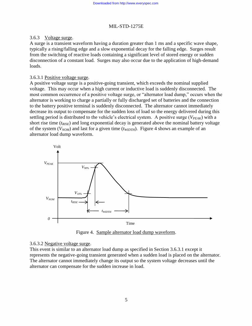
3.6.3.1 Positive voltage surge.
A positive voltage surge is a positive-going transient, which exceeds the nominal supplied
voltage. This may occur when a high current or inductive load is suddenly disconnected. The
most common occurrence of a positive voltage surge, or “alternator load dump,” occurs when the
alternator is working to charge a partially or fully discharged set of batteries and the connection
to the battery positive terminal is suddenly disconnected. The alternator cannot immediately
decrease its output to compensate for the sudden loss of load so the energy delivered during this
settling period is distributed to the vehicle’s electrical system. A positive surge (VPEAK) with a
short rise time (tRISE) and long exponential decay is generated above the nominal battery voltage
of the system (VNOM) and last for a given time (tWIDTH). Figure 4 shows an example of an
alternator load dump waveform.
Figure 4. Sample alternator load dump waveform.
3.6.3.2 Negative voltage surge.
This event is similar to an alternator load dump as specified in Section 3.6.3.1 except it
represents the negative-going transient generated when a sudden load is placed on the alternator.
The alternator cannot immediately change its output so the system voltage decreases until the
alternator can compensate for the sudden increase in load.
Time
Volt
s
0
VNOM
VPEAK
V10%
V90%
tRISE
tWIDTH
Downloaded from http://www.everyspec.com

MIL-STD-1275E
6
3.6.4 Intermittent contact.
Intermittent contact occurs when electrical contacts in a switch or relay change state. A common
way of describing intermittent contacts is the use of the terms “contact bounce” or “chattering
relay.” Mechanical vibration may also affect the operation of mechanical contacts and cause this
to occur. The settling period and pulse widths associated may vary depending on the
construction of the contacts. Figure 5 shows an example of an intermittent contact waveform.
Figure 5. Sample intermittent contact waveform.
Intermittent contact may affect operation of equipment in one of two ways. First, equipment
power feed(s) controlled by the relay/switch may be directly affected with resets, dropouts, etc.
Second, the electrical noise generated by the intermittent contact on a directly connected wire
may be coupled to nearby wires in the wiring harness through electric/magnetic field coupling.
3.7 Reverse polarity.
Reverse polarity is defined as the inverted connection of the EUT’s power terminal(s) to the
vehicle’s power system. The positive (+) terminal of the EUT is connected to the negative (-) or
“ground” terminal of the vehicle’s power supply system. The negative (-) terminal of the EUT is
connected to the positive (+) terminal of the vehicle’s power supply system.
4 GENERAL REQUIREMENTS
4.1 Reverse polarity.
Utilization equipment shall protect itself against damage due to input power with reverse
polarity. With reverse polarity voltage applied to the input power terminals of the utilization
equipment, the magnitude of the reverse polarity input current shall be equal to or less than the
magnitude of the utilization equipment normal operating current.
Time
Volt
s
0
VNOM
Downloaded from http://www.everyspec.com

MIL-STD-1275E
7
4.2 Electromagnetic compatibility.
Utilization equipment shall be compatible with the applicable performance specification
requirements for control of electromagnetic interference and voltage spikes induced by lightning,
electromagnetic pulses, and power switching. Electromagnetic interference is not covered by
this standard.
4.3 Electrostatic discharge.
Utilization equipment shall be compatible with the applicable performance specification
requirements for immunity to electrostatic discharge. Electrostatic discharge is not covered by
this standard.
5 DETAILED REQUIREMENTS
5.1 Voltage compatibility requirements.
This section contains detailed requirements regarding the voltage conditions under which the
utilization equipment is expected to operate. Verification of compliance shall be in accordance
with Sections 5.2 and 5.3 of this document.
5.1.1 Steady state operation.
This section describes the steady state voltage range, which excludes engine starting
disturbances, and applies to all utilization equipment. Utilization equipment shall operate
without degradation or damage when subjected to the operational voltage range specified in this
section.
5.1.1.1 Operational voltage range.
The utilization equipment voltage operating range is between 20 VDC and 33 VDC, including
ripple.
5.1.1.2 Voltage ripple.
The maximum peak-to-peak ripple voltage limits are specified in MIL-STD-461 CS101 with the
same values used at 150 kHz extended to 250 kHz, as shown in Figure CS101-1.
5.1.2 Starting operation.
This section applies to utilization equipment operating while subjected to engine starting
disturbances. Utilization equipment shall operate without degradation or damage when subjected
to engine starting disturbances within the limits shown in Figure 6.
5.1.2.1 Initial engagement surge (IES).
The minimum voltage supplied to utilization equipment during an IES is 12 VDC. The
maximum duration of the IES is one (1) second. Consecutive IES events are a minimum of one
(1) second apart.
5.1.2.2 Cranking surges.
The minimum voltage supplied to utilization equipment during cranking surges is 16 VDC. The
maximum duration of cranking surges is thirty (30) seconds.
Downloaded from http://www.everyspec.com

MIL-STD-1275E
8
Figure 6. Starting disturbance limits on 28VDC systems.
5.1.3 Transient disturbances.
This section describes transient waveforms and applies to all utilization equipment.
5.1.3.1 Voltage spikes.
5.1.3.1.1 Injected voltage spikes.
Utilization equipment shall operate without degradation or damage when subjected to voltage
spikes within the limits shown in Figure 7. The maximum rise time (tRISE) of the injected spikes
is 50 nanoseconds, and the maximum total energy content of a single spike is 2 Joules.
5.1.3.1.2 Emitted voltage spikes.
Emitted voltage spikes from utilization equipment shall be within the limits shown in Figure 7.
The maximum total energy content of a single emitted spike is 125 millijoules (mJ).
5.1.3.2 Voltage surges.
5.1.3.2.1 Injected voltage surges.
Utilization equipment shall operate without degradation or damage when subjected to voltage
surges within the limits shown in Figure 8. The maximum total energy content of a single surge
is 60 Joules (J).
40
Time (s)
25
30
Volts
35
0
33
15
20
10
5
33V
0 1 2 3 28 29 30 31 32
Initial Engagement Surge
Cranking Surges 12V
16V
20V
Notes: The solid line includes ripple voltage.
-1
Downloaded from http://www.everyspec.com

MIL-STD-1275E
9
Figure 7. Envelope of spikes for 28VDC systems.
5.1.3.2.2 Emitted voltage surges.
Emitted voltage surges from utilization equipment shall be within the limits shown in Figure 8.
5.2 Voltage compatibility verification setup.
5.2.1 Environmental conditions.
Testing of the EUT according to this standard shall be performed under the following
environmental conditions:
Temperature: +23°C ± 5°C (+73°F ± 9°F)
Relative Humidity: 0% to 90% humidity
Atmospheric Pressure: 80kPa to 102kPa (23.62 inHg to 30.12 inHg)
Testing under different environmental conditions (e.g., extremes of operating temperature) shall
be conducted at the discretion of the appropriate authority.
The electromagnetic environment (e.g., background noise) shall not interfere with the
measurement instrumentation setup.
-300
-250
-200
-150
-100
-50
0
50
100
150
200
250
300
0 100 200 300 400 500 600 700 800 900 1000
Time (µs)
Volts
100V, 1 ms
-250V, 70µs
250V, 70µs
18V, 1 ms
Utilization equipment may be damaged in this voltage range
Utilization equipment may be damaged in this voltage range
Downloaded from http://www.everyspec.com

MIL-STD-1275E
10
Figure 8. Envelope of surges for 28VDC systems.
5.2.2 Calibration of test equipment.
Test equipment used to verify parameters such as current, voltage, rise/fall time, etc. of the test
setup shall have traceable calibration to a national standards body, such as NIST, and within the
calibration period at the time of the test.
5.2.3 Nominal voltage.
For purposes of verification, the term “nominal” when used to describe voltage shall mean the
stated voltage ±1%, unless otherwise stated.
5.2.4 Measurement tolerance.
The default measurement tolerance shall be ±1% unless otherwise stated.
0
5
10
15
20
25
30
35
40
45
1 100 200 300 400 500 600 700 800 900 1000
Time (ms)
Volts
Notes: The solid line includes ripple voltage. Source Impedance for Injected Surges:
Surges originate from a nominal source impedance of 500 mΩ
95
100
105
20V
33V
18V
20V, 600 ms
33V, 500 ms
100V, 50 ms
18V, 500 ms
Utilization equipment may be inoperable in this voltage range
Utilization equipment may be damaged in this voltage range
Downloaded from http://www.everyspec.com

MIL-STD-1275E
11
5.2.5 Measurement reference point.
The measurement reference point for EUTs shall be the power input terminals of the EUT.
EUTs having multiple power input terminals shall be individually and simultaneously monitored
during the test(s). All transient voltage waveforms applied to EUTs shall be verified open
circuit; i.e., no load.
5.2.6 Power return.
The test setup shall use a power return for the EUT as required by the applicable performance
specification.
If a power return is not specified, the EUT power return conductor shall be equivalent to the
EUT power source conductor.
In cases where the EUT uses the vehicle structure as the power return, a ground plane in
accordance with (IAW) MIL-STD-461 shall be used to simulate the vehicle’s metal structure as
the return current path. The negative (-) terminal of the EUT as well as the negative (-) terminal
of the power source shall be bonded to the ground plane.
5.2.7 Loads.
Loads representative of the actual installation on vehicle shall be used to test the EUT if the EUT
is not a standalone device.
5.2.8 Power supply.
Power supplies shall maintain ±1% of specified voltage during testing, as measured at their
output.
5.3 Voltage compatibility verification method.
5.3.1 Steady state operation.
5.3.1.1 Operational voltage range.
The EUT shall be tested to operate as specified while subjected to the voltages/durations at both
the lower and higher limits of the voltage envelope shown in Figure 8. Any deviation from
normal operation shall be recognized as a failure of the EUT.
5.3.1.2 Voltage ripple.
Unless otherwise specified in the applicable performance specification, the test method and
limits for voltage ripple specified in MIL-STD-461 CS101 shall be used at nominal voltages of
23 VDC and 30 VDC with the same values used at 150 kHz extended to 250 kHz, as shown in
Figures CS101-1 and CS101-2.
Verify the EUT operates as specified while subjected to the ripple. Any deviation from normal
operation shall be recognized as a failure of the EUT.
Downloaded from http://www.everyspec.com

MIL-STD-1275E
12
5.3.2 Starting operation.
When applicable, the EUT shall be tested to operate as specified while subjected to the
voltages/durations of the lower limit of the voltage envelope shown in Figure 6. Any deviation
from normal operation shall be recognized as a failure of the EUT.
5.3.3 Transient disturbances.
5.3.3.1 Voltage spikes.
5.3.3.1.1 Injected voltage spikes.
The EUT shall be supplied power by a voltage source set to the nominal 28 VDC operating
voltage through a Line Impedance Stabilization Network (LISN). The test operator shall inject
voltage spikes into the EUT using a test setup similar to Figure 9.
Figure 9. Sample test setup for immunity to injected voltage spikes.
One LISN shall be used when the power return is the vehicle chassis; in this case the ground
plane provides the power return current path. Two LISNs shall be used when the EUT has a
dedicated power return conductor, such as wires, buss bar, etc. This simulates the additional
vehicle wiring harness present in the vehicle.
Both positive and negative voltage spikes shall be applied to the EUT. A minimum of fifty (50)
250V spikes of each polarity shall be applied at one (1) second intervals. Each test spike shall
have a peak amplitude of 250V, a risetime not exceeding 50 ns, a frequency of oscillation greater
than 100 kHz and less than 500 kHz, and a maximum energy content of 2 Joules.
Verify the EUT operates as specified while subjected to the voltage spikes. Any deviation from
normal operation shall be recognized as a failure of the EUT.
POWER
SUPPLY 5µH
LISN
(+)
(-)
5µH
LISN
EUT
TRANSIENT
GENERATOR
LOADS
Downloaded from http://www.everyspec.com

MIL-STD-1275E
13
5.3.3.1.2 Emitted spikes.
The EUT shall be supplied power by a source set to the nominal 28 VDC operating voltage.
Unless otherwise specified in the applicable performance specification, use the conducted
transient emissions test method specified in SAE J1113-42 to measure the spikes emitted by the
EUT using a test setup similar to Figure .
Figure 10. Sample test setup for exported voltage spikes and surges.
One LISN shall be used when the power return is the vehicle chassis; in this case the ground
plane provides the power return current path. Two LISNs shall be used when the EUT has a
dedicated power return conductor, such as wires, buss bar, etc. This simulates the additional
vehicle wiring harness present in the vehicle.
The test operator shall exercise switching function(s) of the EUT capable of producing spikes,
(e.g., the switching of any inductive loads controlled by the EUT). If the power source to the
EUT is controlled by means of a vehicle mounted switch or relay, the test shall be performed
using this switch or relay. Each switching function shall be exercised a minimum of thirty-two
(32) times in order to give a reasonable probability that the maximum spike voltage is recorded.
The test operator shall monitor the operation of the EUT. Voltage spikes emitted by the EUT
shall be within the limits shown in Figure 7. Any voltage spike or combination of voltage spikes
emitted from a single event shall have an energy content less than 125 mJ.
5.3.3.2 Voltage surges.
5.3.3.2.1 Injected voltage surges.
The test operator shall inject voltage surges into the EUT using a test setup similar to Figure 11.
POWER
SUPPLY 5µH
LISN
(+)
(-)
5µH
LISN
EUT
DIGITAL STORAGE
OSCILLOSCOPE
LOADS
Downloaded from http://www.everyspec.com

MIL-STD-1275E
14
Figure 11. Sample test circuit for immunity to injected voltage surges.
The voltage waveform injected on the power line(s) of the EUT shall simulate the voltage surge
shown in Figure 4. The voltage surge parameters are shown in Table I. Energy emitted from the
transient surge generator shall be limited to 60 Joules.
Table I. Positive voltage surge test parameters.
Operating
Voltage
(Vnom)
Amplitude
(Vpeak)
Rise
Time
(ms)
Duration
(ms)
Source
Impedance
(mΩ)
Number
of
Pulses
Time
Between
Pulses
(s)
30 -0/+1 100 -0/+10 1 < t < 10 50 -0/+5 500 -25/+0 5 5
Prior to connection of the EUT, the test operator shall verify the amplitude and duration of the
voltage surge specified in Table I with a non-inductive load whose resistance is matched to the
source impedance of the transient generator.
Verify the EUT operates as specified while subjected to the voltage surges. Any deviation from
normal operation shall be recognized as a failure of the EUT.
5.3.3.2.2 Emitted voltage surges.
The EUT shall be supplied power by a source set to the nominal 28 VDC operating voltage. The
test operator shall measure voltage surges emitted by the EUT using a test setup similar to Figure
10. The test operator shall exercise function(s) of the EUT capable of producing surges. Each
surge-producing function shall be exercised a minimum of thirty-two (32) times in order to give
a reasonable probability that the maximum surge voltage is recorded.
Downloaded from http://www.everyspec.com

MIL-STD-1275E
15
The test operator shall monitor the operation of the EUT. Voltage surges emitted by the EUT
shall be within the limits shown in Figure 8.
5.3.4 Reverse polarity.
Connect the positive (+) terminal of the EUT to the negative (-) terminal of the power supply
system. Connect the negative (-) terminal of the EUT to the positive (+) terminal of the power
supply system. Set the voltage on the power supply to 33 VDC and leave connected for five (5)
minutes. Connect EUT input terminals to power with the correct polarity and verify device
operates as specified. Any deviation from normal operation shall be recognized as a failure of
the EUT.
5.3.5 Electromagnetic compatibility.
The EUT shall demonstrate compliance with the applicable performance specification
requirements for control of electromagnetic interference and voltage spikes induced by lightning,
electromagnetic pulses, and power switching prior to MIL-STD-1275 testing. Electromagnetic
interference testing is not covered by this standard.
5.3.6 Electrostatic discharge.
The EUT shall demonstrate compliance with the applicable performance specification
requirements for immunity to electrostatic discharge prior to MIL-STD-1275 testing.
Electrostatic discharge testing is not covered by this standard.
6 NOTES
(This section contains information of a general or explanatory nature, which may be helpful, but
is not mandatory.)
6.1 Intended use.
The intent of this document is to describe the nominal 28 VDC voltage characteristics, common
across military ground vehicles, at the input power terminal of the utilizing electrical and
electronic assemblies directly connected to the distribution network. This lays the groundwork
for commonality across vehicle platforms. The vehicle’s design authority is responsible to
ensure that the 28 VDC delivered to the input power terminal of the utilization equipment meets
these requirements.
6.2 Acronyms.
Acronym Definition
EUT Equipment Under Test
IAW In Accordance With
IES Initial Engagement Surge
LISN Line Impedance Stabilization Network
NIST National Institute of Standards and Technology
SAE Society of Automotive Engineers
Downloaded from http://www.everyspec.com

MIL-STD-1275E
16
6.3 International interest.
Certain provisions of this standard are the subject of international standardization agreement
NATO STANAG 2601. When a change notice, revision, or cancellation of this standard is
proposed which will modify the international agreement concerned, the preparing activity will
take appropriate action through international standardization channels, including departmental
standardization offices, to change the agreement or make other appropriate accommodations.
6.4 Changes from previous issue.
Marginal notations are not used in this revision to identify changes with respect to the previous
issue due to the extent of the changes.
6.5 Subject term (key word) listing.
Polarity
Recovery time
Ripple
Rise time
Spike
Starting disturbance
Surge
Voltage
Custodian: Preparing Activity:
Army – AT Army - AT
Review Activities: Project 2920-2013-001
Army - CR, MI, TE
DLA - CC
NOTE: The activities listed above were interested in this document as of the date of this
document. Since organizations and responsibilities can change, you should verify the currency of
the information above using the ASSIST Online, database at https://assist.dla.mil.
Downloaded from http://www.everyspec.com