department of civil engineering - · pdf filedepartment of civil engineering ... 2 measurement...
TRANSCRIPT
Survey Practical - II
CHENNAI INSTITUTE OF TECHNOLOGY
CHENNAI– 600 069
Dept : CIVIL
Year : II
Sem : IV
Department of Civil Engineering
LAB MANUAL
CE6407 SURVEY PRACTICAL – II

Survey Practical - II
CHENNAI INSTITUTE OF TECHNOLOGY
CHENNAI– 600 069
Dept : CIVIL
Year : II
Sem : IV
CE2259 SURVEY PRACTICAL – II
INDEX
LIST OF EXPERIMENTS
Sl.No DATE NAME OF THE EXPERIMENT MARKS SIGN
1 Study of Theodolite
2 Measurement of horizontal angles by
General method
3 Measurement of horizontal angles by
Reiteration method
4 Measurement of horizontal angles by
Repetition method
5 Measurement of vertical angles
6 Theodolite traversing – Included angle
method
7 Theodolite traversing – Direct (or)
Deflection angle method
8 Heights and distances - Triangulation -
Single plane method
9 Tacheometry - Stadia system.
10 Tacheometry - Tangential system.
11 Tacheometry - Subtense system.
12 Setting out works - Foundation marking.
13 Setting out works - Simple curve
(right/left-handed).
14 Setting out works - Transition curve.
15 Field observation for and Calculation of
azimuth
16 Study of Total Station.

Survey Practical - II
CHENNAI INSTITUTE OF TECHNOLOGY
CHENNAI– 600 069
Dept : CIVIL
Year : II
Sem : IV
Survey Practical - II
CHENNAI INSTITUTE OF TECHNOLOGY
CHENNAI– 600 069
Dept : CIVIL
Year : II
Sem : IV
STUDY OF THEODOLITE Exp no: Date:
Aim:
To study about the Temporary and Permanent adjustments of a Theodolite.
Instrument used:
Theodolite
Procedure:
ADJUSTMENTS OF THEODOLITE
The Theodolite should be properly adjusted to obtain accurate observations. The
adjustments are mainly of two types. They are as follows:
1. Permanent adjustments and
2. Temporary adjustments.
1. Permanent adjustments
The permanent adjustments are to be done to maintain the required standard relationship
between the fundamental lines (axes) of a Theodolite. The fundamental lines are as follows:
a. Vertical axis
b. Horizontal axis or trunnion axis
c. Line of collimation or line of sight
d. Axis of plate level
e. Axis of altitude level.
Required relations between the fundamental lines (axes)
i) The axis of plate level must be perpendicular to the vertical axis.
ii) The line of collimation must be perpendicular to the horizontal axis
iii) The horizontal axis must be perpendicular to the vertical axis.
iv) The axis of the altitude level must be parallel to the line of collimation.
v) The vernier reading of vertical circle must read zero when the line of collimation is
horizontal.
The permanent adjustments of a Theodolite are:
Adjustment of plate level.
Adjustment of line of sight
Adjustment of horizontal axis
Adjustment of altitude bubble and vertical index frame.
2. Temporary adjustments
The adjustments which are carried out at every setting of the instrument before the
observations are referred as temporary adjustments. There are three types of temporary
adjustments as follows.
Survey Practical - II
CHENNAI INSTITUTE OF TECHNOLOGY
CHENNAI– 600 069
Dept : CIVIL
Year : II
Sem : IV
a. Setting up
b. Levelling up
c. Elimination of parallax.
a) Setting up
This adjustment includes the following two operations.
i. Centering the Theodolite over the instrument station.
ii. Approximate leveling of Theodolite with the help of the tripod legs only.
Centering
It is the operation by which the vertical axis of the theodolite represented by a plumb line is
made to pass through the mark of instrument station on the ground.
Approximate levelling
The approximate leveling may be done with the reference to a small circular bubble
provided on the tribrach or by eye judgements.
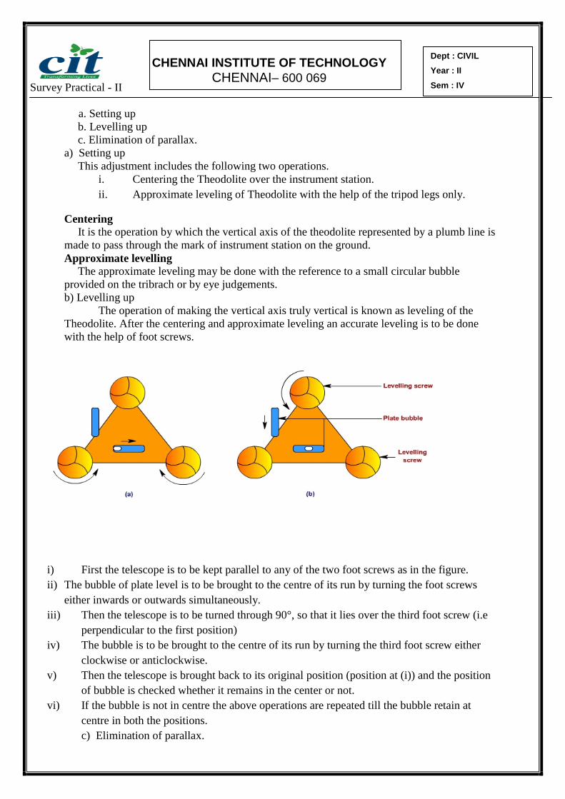
b) Levelling up
The operation of making the vertical axis truly vertical is known as leveling of the
Theodolite. After the centering and approximate leveling an accurate leveling is to be done
with the help of foot screws.
i) First the telescope is to be kept parallel to any of the two foot screws as in the figure.
ii) The bubble of plate level is to be brought to the centre of its run by turning the foot screws
either inwards or outwards simultaneously.
iii) Then the telescope is to be turned through 90°, so that it lies over the third foot screw (i.e
perpendicular to the first position)
iv) The bubble is to be brought to the centre of its run by turning the third foot screw either
clockwise or anticlockwise.
v) Then the telescope is brought back to its original position (position at (i)) and the position
of bubble is checked whether it remains in the center or not.
vi) If the bubble is not in centre the above operations are repeated till the bubble retain at
centre in both the positions.
c) Elimination of parallax.
Survey Practical - II
CHENNAI INSTITUTE OF TECHNOLOGY
CHENNAI– 600 069
Dept : CIVIL
Year : II
Sem : IV
An apparent change in the position of an object caused by the change in position
of the observer’s eye is known as parallax. This can be eliminated in two steps.
i) Focusing the eye piece for distinct vision of the cross hairs.
ii) Focusing the objective to bring the image of the object in the plane of cross
hairs.
i) Focusing the eye piece
The telescope is to be pointed towards the sky or a sheet of white paper is to be
hold in front of the objective.
The eye piece is to be moved in or out by rotating it gradually until the
appearance of cross hairs becomes sharp and distinct.
ii) Focusing the objective
Telescope is to be directed towards the object. Focusing screw is to be turned until
the appearance of the object becomes sharp and clear.

Survey Practical - II
CHENNAI INSTITUTE OF TECHNOLOGY
CHENNAI– 600 069
Dept : CIVIL
Year : II
Sem : IV
Result:
Thus the study about the Temporary and Permanent adjustments of a Theodolite is
practiced.
MARKS out of 10: Signature of the staff in-charge
Survey Practical - II
CHENNAI INSTITUTE OF TECHNOLOGY
CHENNAI– 600 069
Dept : CIVIL
Year : II
Sem : IV
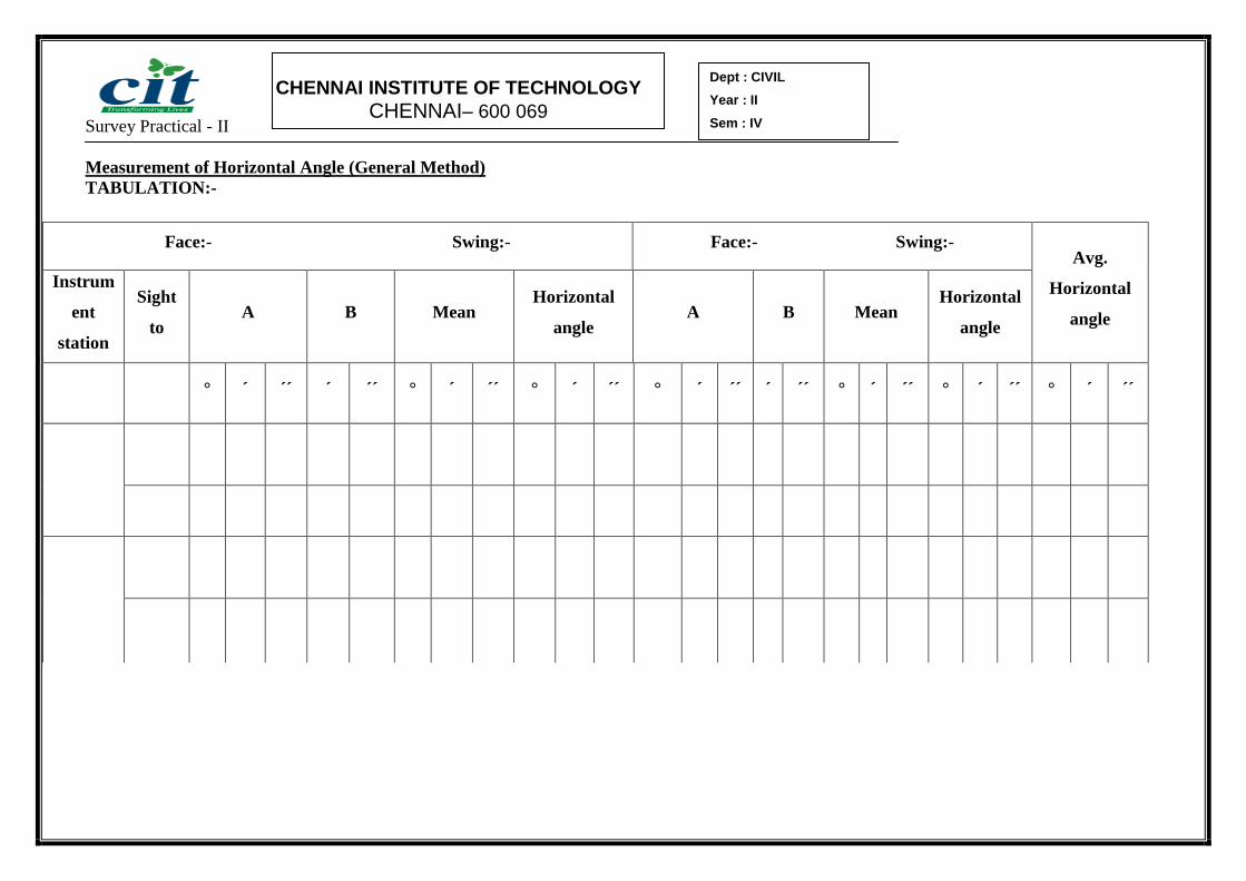
Measurement of Horizontal Angle (General Method)
TABULATION:-
Face:- Swing:- Face:- Swing:- Avg.
Horizontal
angle
Instrum
ent
station
Sight
to A B Mean
Horizontal
angle A B Mean
Horizontal
angle
° ´ ´´ ´ ´´ ° ´ ´´ ° ´ ´´ ° ´ ´´ ´ ´´ ° ´ ´´ ° ´ ´´ ° ´ ´´

Survey Practical - II
CHENNAI INSTITUTE OF TECHNOLOGY
CHENNAI– 600 069
Dept : CIVIL
Year : II
Sem : IV
Expt. No.2 MEASUREMENT OF HORIZONTAL ANGLES Date: ------------
BY GENERAL METHOD
AIM
To measure the horizontal angle by General method with the use of Theodolite.
APPARATUS USED
1.Theodolite, 2.Ranging rods,3.Pegs or Arrows.
PROCEDURE
1. Theodolite is set over an instrument station (O) exactly and all the temporary
adjustments are done.
2. Vertical circle is placed left to the observer (face left observation).
3. Vernier A is set to Zero with the help of upper clamp screw and tangent screws.
4. Readings of Vernier A and B are noted.
5. Upper clamp is clamped. Lower clamp is loosened and the telescope is turned
towards “P”. Lower clamp is clamped and the point “P” is bisected exactly using
tangent screws.
6. Both the vernier A and B are read and noted (Must be equal to 0° and 180°
respectively).
7. Upper clamp is unclamped and the telescope is turned clockwise and “Q” is
bisected.
8. Upper clamp is clamped and “Q” is bisected exactly using tangent screws.
9. Both the verniers are read. Mean of the readings provide an approximate included
angle of POQ.
10. The reading of vernier A gives directly the angle POQ, and 180° is subtracted by the
reading of vernier B. The mean value of two readings gives the angle POQ with one face.
11. The face is changed by transiting (Face right observation) and the whole process
is repeated. Mean value of POQ is obtained with other face.
12. The average horizontal angle is obtained by taking the mean of the values obtained with
the two faces.

Survey Practical - II
CHENNAI INSTITUTE OF TECHNOLOGY
CHENNAI– 600 069
Dept : CIVIL
Year : II
Sem : IV
Calculation:

Survey Practical - II
CHENNAI INSTITUTE OF TECHNOLOGY
CHENNAI– 600 069
Dept : CIVIL
Year : II
Sem : IV
13. The face is changed by transiting (Face right observation) and the whole process
is repeated. Mean value of POQ is obtained with other face.
14. The average horizontal angle is obtained by taking the mean of the values
obtained with the two faces.
RESULT:
The horizontal angle measured at O between P and Q i.e POQ
a) With face left:-
b) With face right:-
c) Average:-
MARKS out of 10: Signature of the staff in-charge

Survey Practical - II
CHENNAI INSTITUTE OF TECHNOLOGY
CHENNAI– 600 069
Dept : CIVIL
Year : II
Sem : IV
Measurement of Horizontal Angle (Repetition Method)
TABULATION:-
Face:- Swing:- Face:- Swing:- Avg.
Horizontal
angle
Instrum
ent
station
Sight
to A B Mean
Horizontal
angle A B Mean
Horizontal
angle
° ´ ´´ ´ ´´ ° ´ ´´ ° ´ ´´ ° ´ ´´ ´ ´´ ° ´ ´´ ° ´ ´´ ° ´ ´´
Survey Practical - II
CHENNAI INSTITUTE OF TECHNOLOGY
CHENNAI– 600 069
Dept : CIVIL
Year : II
Sem : IV
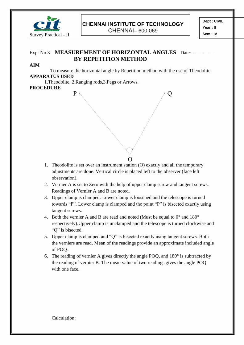
Expt No.3 MEASUREMENT OF HORIZONTAL ANGLES Date: -------------
BY REPETITION METHOD
AIM
To measure the horizontal angle by Repetition method with the use of Theodolite.
APPARATUS USED
1.Theodolite, 2.Ranging rods,3.Pegs or Arrows.
PROCEDURE
1. Theodolite is set over an instrument station (O) exactly and all the temporary
adjustments are done. Vertical circle is placed left to the observer (face left
observation).
2. Vernier A is set to Zero with the help of upper clamp screw and tangent screws.
Readings of Vernier A and B are noted.
3. Upper clamp is clamped. Lower clamp is loosened and the telescope is turned
towards “P”. Lower clamp is clamped and the point “P” is bisected exactly using
tangent screws.
4. Both the vernier A and B are read and noted (Must be equal to 0° and 180°
respectively).Upper clamp is unclamped and the telescope is turned clockwise and
“Q” is bisected.
5. Upper clamp is clamped and “Q” is bisected exactly using tangent screws. Both
the verniers are read. Mean of the readings provide an approximate included angle
of POQ.
6. The reading of vernier A gives directly the angle POQ, and 180° is subtracted by
the reading of vernier B. The mean value of two readings gives the angle POQ
with one face.
Calculation:

Survey Practical - II
CHENNAI INSTITUTE OF TECHNOLOGY
CHENNAI– 600 069
Dept : CIVIL
Year : II
Sem : IV

Survey Practical - II
CHENNAI INSTITUTE OF TECHNOLOGY
CHENNAI– 600 069
Dept : CIVIL
Year : II
Sem : IV
7. Lower clamp is unclamped and the telescope is turned anticlockwise to sight P
again. Lower clamp is clamped and P is bisected exactly using tangent screws.
8. Upper clamp is loosened and the telescope is turned clockwise and Q is bisected.
Upper clamp is clamped and Q is bisected exactly using tangent screws. The
vernier now read twice the value of angle POQ.
9. Last two steps (7&8) are repeated once again to get the thrice value of angle POQ.
10. Finally obtained reading is divided by 3 to get the mean value of angle POQ.
11. The face is changed and the whole process is repeated. (Face right observations).
12. Average value of two horizontal angles obtained with face left and face right
observations is determined.
RESULT:
The horizontal angle measured at O between P and Q. i.e POQ
a) With face left:-
b) With face right:-
c) Average:-
MARKS out of 10: Signature of the staff in-charge
Survey Practical - II
CHENNAI INSTITUTE OF TECHNOLOGY
CHENNAI– 600 069
Dept : CIVIL
Year : II
Sem : IV
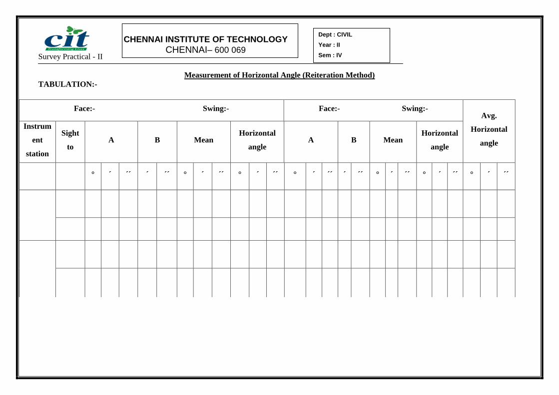
Measurement of Horizontal Angle (Reiteration Method)
TABULATION:-
Face:- Swing:- Face:- Swing:- Avg.
Horizontal
angle
Instrum
ent
station
Sight
to A B Mean
Horizontal
angle A B Mean
Horizontal
angle
° ´ ´´ ´ ´´ ° ´ ´´ ° ´ ´´ ° ´ ´´ ´ ´´ ° ´ ´´ ° ´ ´´ ° ´ ´´
Survey Practical - II
CHENNAI INSTITUTE OF TECHNOLOGY
CHENNAI– 600 069
Dept : CIVIL
Year : II
Sem : IV
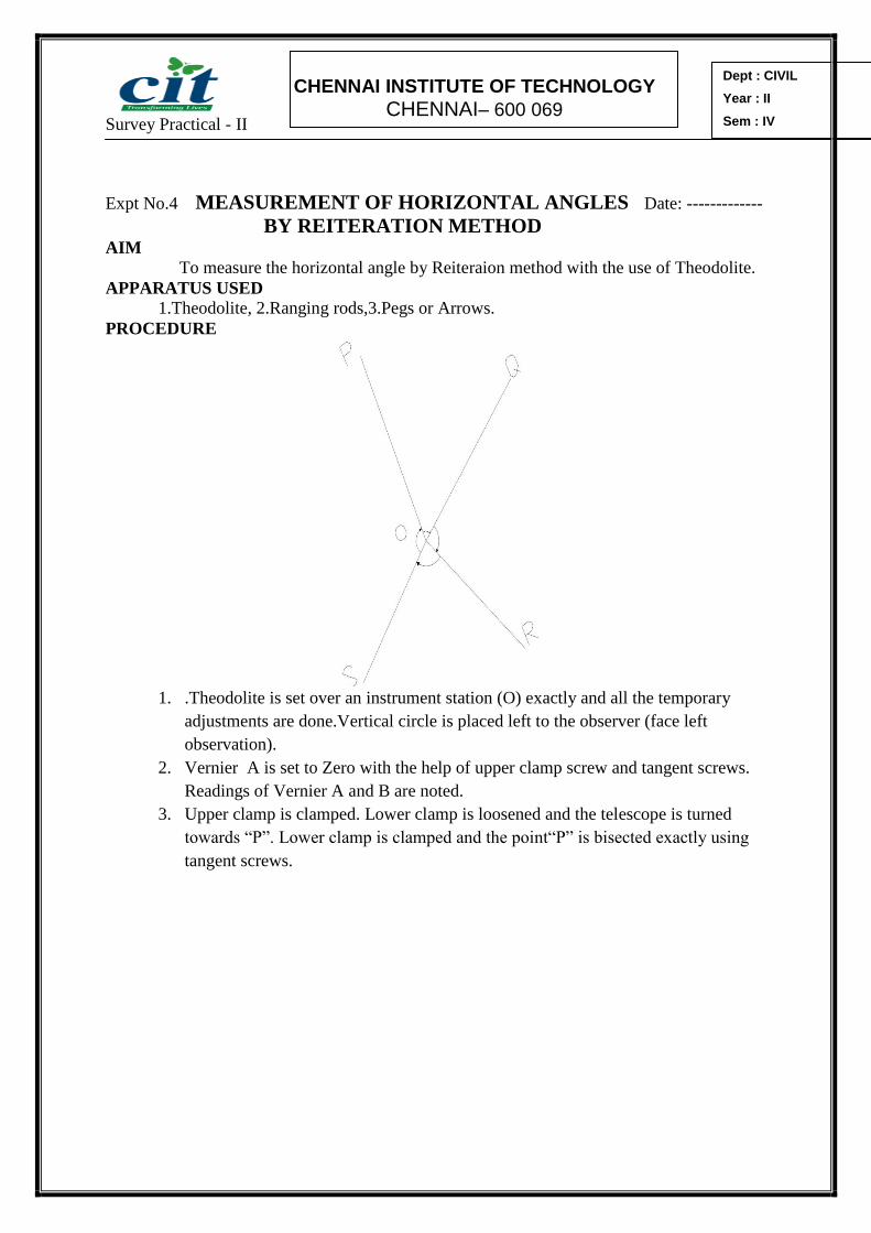
Expt No.4 MEASUREMENT OF HORIZONTAL ANGLES Date: -------------
BY REITERATION METHOD
AIM
To measure the horizontal angle by Reiteraion method with the use of Theodolite.
APPARATUS USED
1.Theodolite, 2.Ranging rods,3.Pegs or Arrows.
PROCEDURE
1. .Theodolite is set over an instrument station (O) exactly and all the temporary
adjustments are done.Vertical circle is placed left to the observer (face left
observation).
2. Vernier A is set to Zero with the help of upper clamp screw and tangent screws.
Readings of Vernier A and B are noted.
3. Upper clamp is clamped. Lower clamp is loosened and the telescope is turned
towards “P”. Lower clamp is clamped and the point“P” is bisected exactly using
tangent screws.

Survey Practical - II
CHENNAI INSTITUTE OF TECHNOLOGY
CHENNAI– 600 069
Dept : CIVIL
Year : II
Sem : IV
Calculation:

Survey Practical - II
CHENNAI INSTITUTE OF TECHNOLOGY
CHENNAI– 600 069
Dept : CIVIL
Year : II
Sem : IV
4. Upper clamp is loosened and the telescope is turned clockwise to bisect R.Lower
clamp is clamped and R is bisected exactly using tangent screws. Both the
verniers are read and noted.
5. The same procedure is repeated for all other points.
6. The face is changed and all the above steps are repeated. (Face right
observations).
7. Reading from Q is subtracted by reading R to get included angle QOR. Reading
from R is subtracted by reading S to get included angle ROS.
8. The same procedure is followed to get readings of all other included angles.
RESULT: The horizontal angle between the points
i) Face Left ii) Face Right
POQ = POQ =
QOR = QOR =
ROS = ROS =
SOP = SOP =
MARKS out of 10: Signature of the staff in-charge

Survey Practical - II
CHENNAI INSTITUTE OF TECHNOLOGY
CHENNAI– 600 069
Dept : CIVIL
Year : II
Sem : IV

Survey Practical - II
CHENNAI INSTITUTE OF TECHNOLOGY
CHENNAI– 600 069
Dept : CIVIL
Year : II
Sem : IV
Measurement of Vertical Angle
TABULATION:-
Face:- Swing:- Face:- Swing:- Avg.
Vertical
angle
Instrum
ent
station
Sight
to A B Mean
Vertical
angle A B Mean
Vertical
angle
° ´ ´´ ´ ´´ ° ´ ´´ ° ´ ´´ ° ´ ´´ ´ ´´ ° ´ ´´ ° ´ ´´ ° ´ ´´

Survey Practical - II
CHENNAI INSTITUTE OF TECHNOLOGY
CHENNAI– 600 069
Dept : CIVIL
Year : II
Sem : IV
Expt No.5 MEASUREMENT OFVERTICAL ANGLES Date: ----------------- AIM
To measure the vertical angle between two objects with the use of Theodolite.
APPARATUS USED
1. Theodolite, 2.Ranging rod, 3.Peg or an Arrow.
PROCEDURE
a. Angle of Elevation b. Angle of
Depression
1. Theodolite is set up, centered and leveled with reference to the plate bubble.
2. Telescope is placed horizontally by setting the reading of 0°0’0”in the verniers of C
and D.
3. Levelling process is carried out with the help of foot screws and the altitude bubble is
brought in its central run.
4. Vertical circle clamp is loosened and the telescope is directed upwards to bisect P.
5. Vertical circle clamp is clamped and the point P is exactly bisected using vertical
tangent screws.
6. Both the verniers of C and D are read and noted. Mean of the two verniers provide
the vertical angle HOP.
7. Face is changed and all the above steps are repeated to get one more vertical angle
HOP.
8. Average of the vertical angles taken to get an accurate vertical angle.
9. The same procedure may be adopted to determine the angle of depression HOR by
directing the telescope downwards.

Survey Practical - II
CHENNAI INSTITUTE OF TECHNOLOGY
CHENNAI– 600 069
Dept : CIVIL
Year : II
Sem : IV
Calculation:
Calculation:

Survey Practical - II
CHENNAI INSTITUTE OF TECHNOLOGY
CHENNAI– 600 069
Dept : CIVIL
Year : II
Sem : IV
RESULT:
1. The observed angle of Elevation is --------------------
2. The observed angle of Depression is --------------------
MARKS out of 10: Signature of the staff in-charge

Survey Practical - II
CHENNAI INSTITUTE OF TECHNOLOGY
CHENNAI– 600 069
Dept : CIVIL
Year : II
Sem : IV
Expt No.6 THEODOLITE TRAVERSING – Date:-

Survey Practical - II
CHENNAI INSTITUTE OF TECHNOLOGY
CHENNAI– 600 069
Dept : CIVIL
Year : II
Sem : IV
INCLUDED ANGLE METHOD AIM
To determine the lengths and included angles between the lines of closed traverse
with the use of Theodolite.
APPARATUS USED
1.Theodolite, 2.Ranging rods,3.Pegs or Arrows.
GENERAL
This method is normally provided for closed traverse. In this method included
angle between two successive lines is measured.
PROCEDURE
1. The instrument is set up over the station “P” and all the temporary adjustments are
made. Telescope is oriented along the magnetic meridian and the magnetic
meridian of PQ is measured.
2. The reading of 0°0’0”is set at vernier A by using upper clamp and tangent screw
and the face of Theodolite is kept as left.
3. The telescope is brought back in the line of PT with the help of lower clamp and
tangent screw, the reading in vernier A is kept as 0°0’0” and the reading in vernier
B is kept as 180°0’0”.
4. Upper clamp is loosened and the telescope is turned clockwise and “Q” is
bisected. Upper clamp is clamped and “Q” is bisected exactly using tangent
screws.
5. Both the verniers of A and B are read and noted. Mean of the two verniers is
determined as an included angle QPT.
6. Face is changed and all the above steps are repeated to determine one more
included angle QPT. The average of the two included angle QPT is measured.
7. The Theodolite is shifted to second station Q. The station P is bisected and the
whole process is repeated to get an included angle of RQP.
8. Similarly included angles at R,S and T are measured.
9. Lengths of traverse lines PQ,QR,RS,ST and TP are measured using a tape or
chain.

Survey Practical - II
CHENNAI INSTITUTE OF TECHNOLOGY
CHENNAI– 600 069
Dept : CIVIL
Year : II
Sem : IV
Theodolite Traversing (Included Angle Method)
TABULATION:-
Face:- Swing:- Face:- Swing:- Avg.
Hori.
angle Inst
stn Sight to A B Mean
Horizontal
angle A B Mean
Horizontal
angle
° ´ ´´ ´ ´´ ° ´ ´´ ° ´ ´´ ° ´ ´´ ´ ´´ ° ´ ´´ ° ´ ´´ ° ´ ´´

Survey Practical - II
CHENNAI INSTITUTE OF TECHNOLOGY
CHENNAI– 600 069
Dept : CIVIL
Year : II
Sem : IV

Survey Practical - II
CHENNAI INSTITUTE OF TECHNOLOGY
CHENNAI– 600 069
Dept : CIVIL
Year : II
Sem : IV
Calculation:

Survey Practical - II
CHENNAI INSTITUTE OF TECHNOLOGY
CHENNAI– 600 069
Dept : CIVIL
Year : II
Sem : IV
RESULT:
1. The included angle between the lines
i) Face Left ii) Face Right
QPT = QPT =
RQP = RQP =
SRQ = SRQ =
TSR = TSR =
PTS = PTS =
2. Length of lines
i) PT =
ii) TS =
iii) SR =
iv) RQ =
v) QP =
MARKS out of 10: Signature of the staff in-charge

Survey Practical - II
CHENNAI INSTITUTE OF TECHNOLOGY
CHENNAI– 600 069
Dept : CIVIL
Year : II
Sem : IV
Survey Practical - II
CHENNAI INSTITUTE OF TECHNOLOGY
CHENNAI– 600 069
Dept : CIVIL
Year : II
Sem : IV
Expt No.7 THEODOLITE TRAVERSING – Date:-
DEFLECTION ANGLE METHOD AIM
To measure the deflection angles between the lines of open traverse with the use of
Theodolite.
APPARATUS USED
1. Theodolite, 2. Ranging rods, 3. Pegs or Arrows.
GENERAL
Direct (or) Deflection angle is the angle measured clockwise (or) to the right from
the previous line to the following line. This method is generally used in open traverse.
PROCEDURE
1. Theodolite is set up over P.
2. Magnetic bearing of line PQ is measured.
3. Theodolite is shifted to Q. Vernier A is set to zero using upper clamp and its
tangent screw.
4. Telescope is back sighted to P. Vernier A still read zero.
5. Upper clamp is loosened and the telescope is turned clockwise to bisect “R”.
Upper clamp is clamped.
6. Both the verniers are read and noted. Mean of the two verniers A and B give the
direct angle PQR.
7. Face is changed and again the direct angle PQR is measured.
8. Average of two values is the required direct angle PQR.
9. Similarly all the other direct angles are measured.
10. The lengths of traverse lines are measured and the details are noted.

Survey Practical - II
CHENNAI INSTITUTE OF TECHNOLOGY
CHENNAI– 600 069
Dept : CIVIL
Year : II
Sem : IV
Theodolite Traversing (Deflection Angle Method)
TABULATION:-
Face:- Swing:- Face:- Swing:- Avg.
Hori.
angle Inst
stn Sight to A B Mean
Horizontal
angle A B Mean
Horizontal
angle
° ´ ´´ ´ ´´ ° ´ ´´ ° ´ ´´ ° ´ ´´ ´ ´´ ° ´ ´´ ° ´ ´´ ° ´ ´´

Survey Practical - II
CHENNAI INSTITUTE OF TECHNOLOGY
CHENNAI– 600 069
Dept : CIVIL
Year : II
Sem : IV

Survey Practical - II
CHENNAI INSTITUTE OF TECHNOLOGY
CHENNAI– 600 069
Dept : CIVIL
Year : II
Sem : IV
Calculation:

Survey Practical - II
CHENNAI INSTITUTE OF TECHNOLOGY
CHENNAI– 600 069
Dept : CIVIL
Year : II
Sem : IV
RESULT:
1. The deflection angle between the lines
PQ =
QR =
RS =
ST =
2. Length of lines
i) PQ=
ii) QR =
iii) RS =
iv) ST=
MARKS out of 10: Signature of the staff in-charge

Survey Practical - II
CHENNAI INSTITUTE OF TECHNOLOGY
CHENNAI– 600 069
Dept : CIVIL
Year : II
Sem : IV

Survey Practical - II
CHENNAI INSTITUTE OF TECHNOLOGY
CHENNAI– 600 069
Dept : CIVIL
Year : II
Sem : IV
Expt No.8 HEIGHTS AND DISTANCES - SINGLE PLANE METHOD. Date--
AIM
To determine the height of the given object when the base is inaccessible using
single plane method.
APPARATUS USED
1. Theodolite, 2. Chain (or) Tape 3.Ranging rods, 3. Pegs or Arrows.
PROCEDURE
1 Theodolite is set over an instrument station (A) exactly and all the temporary
adjustments are done.
2 The verniers C and D are set to read zero by means of vertical circle clamping
screw and tangent screw.(Telescope is held at horizontal position).
3 Back sight reading is taken on BM.
4 Telescopic clamping screw is unclamped and the telescope is turned in the vertical
plane to sight the object “P”. Vertical angle α1 is noted.
5 Another station “B” is selected at a distance of “d” from A. The line AB is called
as Base line.
6 Theodolite is shifted to B and the above procedure is repeated at the station B
also.
7 The distance between the station A and P is determined using the following
equation
D = 21
2
tantan
tan
hd
Note:- i) “+” ve sign is to be used in numerator when ab
ii)“_” ve sign is to be used in numerator when ab
iii) h = 0 when a = b.
8 Vertical distance V1 is calculated using the following equation
V1 = D tan α1.
9 R.L of point “P” is determined as follows:
R.L of point “P” = R.L of B.M + a+ V1
(or)
R.L of B.M + b+ V2

Survey Practical - II
CHENNAI INSTITUTE OF TECHNOLOGY
CHENNAI– 600 069
Dept : CIVIL
Year : II
Sem : IV
Calculation:

Survey Practical - II
CHENNAI INSTITUTE OF TECHNOLOGY
CHENNAI– 600 069
Dept : CIVIL
Year : II
Sem : IV
HEIGHTS AND DISTANCES - SINGLE PLANE METHOD.
TABULATION:-
Face:- Swing:- Face:- Swing:-
Inst
stn Sight to C D Mean
Vertical
angle A B Mean
Horizontal
angle
° ´ ´´ ´ ´´ ° ´ ´´ ° ´ ´´ ° ´ ´´ ´ ´´ ° ´ ´´ ° ´ ´´

Survey Practical - II
CHENNAI INSTITUTE OF TECHNOLOGY
CHENNAI– 600 069
Dept : CIVIL
Year : II
Sem : IV

Survey Practical - II
CHENNAI INSTITUTE OF TECHNOLOGY
CHENNAI– 600 069
Dept : CIVIL
Year : II
Sem : IV

Survey Practical - II
CHENNAI INSTITUTE OF TECHNOLOGY
CHENNAI– 600 069
Dept : CIVIL
Year : II
Sem : IV
RESULT:
The height of the given object “P” is determined as ----------m when the
base is inaccessible, using single plane method.
MARKS out of 10: Signature of the staff in-charge

Survey Practical - II
CHENNAI INSTITUTE OF TECHNOLOGY
CHENNAI– 600 069
Dept : CIVIL
Year : II
Sem : IV
Survey Practical - II
CHENNAI INSTITUTE OF TECHNOLOGY
CHENNAI– 600 069
Dept : CIVIL
Year : II
Sem : IV
Expt No.9 TACHEOMETRY - STADIA SYSTEM Date: ----
----------- AIM
To determine the distance and elevation of a point using tacheometric stadia
system.
APPARATUS USED
1.Tacheometer, 2. Levelling staff , 3. Pegs or Arrows.
PROCEDURE
1. Tacheometer is set over an instrument station (O) exactly and all the temporary
adjustments are done.
2. The verniers C and D are set to read zero by means of vertical circle clamping
screw and tangent screw.(Telescope is held at horizontal position).
3. Back sight reading is taken on BM.
4. Telescopic clamping screw is unclamped and the telescope is turned in the vertical
plane to sight the leveling staff which is placed over the object “P”. Vertical angle
α is noted. Staff intercept (S) is also determined.
5. The horizontal distance between O and P is determined as follows:-
OP = D = K S cos2α + A cos
α
6. Difference in elevation between O and P is determined as follows:-
V =
sin2
2sinA
KS
7. R.L of point “P” is determined as follows:
R.L of point “P” = R.L of Line of collimation + V- h

Survey Practical - II
CHENNAI INSTITUTE OF TECHNOLOGY
CHENNAI– 600 069
Dept : CIVIL
Year : II
Sem : IV
TACHEOMETRY - STADIA SYSTEM
TABULATION:-
Staff Reading on Bench Mark =
Instrument
Station Sight to
Face:- Swing:- Face:- Swing:- Stadia Readings
Horizontal Angle Vertical Angle
Top Centre Bottom A B Mean C D Mean
° ´ ´´ ´ ´´ ° ´ ´´ ° ´ ´´ ´ ´´ ° ´ ´´

Survey Practical - II
CHENNAI INSTITUTE OF TECHNOLOGY
CHENNAI– 600 069
Dept : CIVIL
Year : II
Sem : IV
Calculation:

Survey Practical - II
CHENNAI INSTITUTE OF TECHNOLOGY
CHENNAI– 600 069
Dept : CIVIL
Year : II
Sem : IV

Survey Practical - II
CHENNAI INSTITUTE OF TECHNOLOGY
CHENNAI– 600 069
Dept : CIVIL
Year : II
Sem : IV
RESULT:
i) Horizontal distance between O and P =
ii) Difference in elevation between O and P =
iii) R.L of “P” =
MARKS out of 10: Signature of the staff in-charge

Survey Practical - II
CHENNAI INSTITUTE OF TECHNOLOGY
CHENNAI– 600 069
Dept : CIVIL
Year : II
Sem : IV

Survey Practical - II
CHENNAI INSTITUTE OF TECHNOLOGY
CHENNAI– 600 069
Dept : CIVIL
Year : II
Sem : IV
Expt No.10 TACHEOMETRY – TANGENTIAL SYSTEM Date: ----
---------- AIM
To determine the distance and elevation of a point using tangential tacheometric
system.
APPARATUS USED
1.Tacheometer, 2. Levelling staff , 3. Pegs or Arrows.
PROCEDURE
1. Tacheometer is set over an instrument station (O) exactly and all the temporary
adjustments are done.
2. The verniers C and D are set to read zero by means of vertical circle clamping screw
and tangent screw.(Telescope is held at horizontal position).
3. Back sight reading is taken on BM.
4. Telescopic clamping screw is unclamped and the telescope is turned in the vertical
plane to sight the leveling staff which is placed over the object “Q”.
5. Upper target reading (R1) is bisected exactly with the help of telescope clamping
screw and its tangential screw. Vertical angle α1 is noted.
6. Similarly the lower target reading (R2) is bisected and Vertical angle α2 is noted.
From the geometry of the figure, difference in elevation are determined as follows:-
MN = D tan α1
M B= D tan α2
7. The horizontal distance between O and Q is determined as follows:-
D = 21 tantan
S
8. R.L of point “Q” is determined as follows:
R.L of point “Q” = R.L of Line of collimation +MB - R2
(or)
= R.L of Line of collimation +MN – R1

Survey Practical - II
CHENNAI INSTITUTE OF TECHNOLOGY
CHENNAI– 600 069
Dept : CIVIL
Year : II
Sem : IV
Calculation:

Survey Practical - II
CHENNAI INSTITUTE OF TECHNOLOGY
CHENNAI– 600 069
Dept : CIVIL
Year : II
Sem : IV
TACHEOMETRY – TANGENTIAL SYSTEM
TABULATION:-
taff Reading on Bench Mark =
Instrument
Station Sight to
Face:- Swing:- Face:- Swing:- Stadia Readings
Horizontal Angle Vertical Angle
Top Centre Bottom A B Mean C D Mean
° ´ ´´ ´ ´´ ° ´ ´´ ° ´ ´´ ´ ´´ ° ´ ´´

Survey Practical - II
CHENNAI INSTITUTE OF TECHNOLOGY
CHENNAI– 600 069
Dept : CIVIL
Year : II
Sem : IV

Survey Practical - II
CHENNAI INSTITUTE OF TECHNOLOGY
CHENNAI– 600 069
Dept : CIVIL
Year : II
Sem : IV
RESULT:
i) Horizontal distance between O and Q=
ii) Difference in elevation between O and Q=
iii) R.L of “Q” =
MARKS out of 10: Signature of the staff in-charge

Survey Practical - II
CHENNAI INSTITUTE OF TECHNOLOGY
CHENNAI– 600 069
Dept : CIVIL
Year : II
Sem : IV
Expt No.11 TACHEOMETRY – SUBTENSE SYSTEM Date:--- AIM
To determine the distance between any two points using a substance bar. .
APPARATUS USED
1. Tacheometer,2. Sudtense bar, 3. Tripod , 4. Pegs or Arrows.
GENERAL
Subtense method is an indirect method of distance determination. This method
essentially consists of measuring the angle subtended by two ends of a horizontal rod of fixed
length, called subtense bar.
PROCEDURE
1 Two targets of subtense bar are connected at its ends by invar wires with slight
tension to minimize the effect of variations in temperature.
2 The subtense bar is mounted on tripod and centered over the required station.
3 The bar is leveled by centering a circular level bubble using three leveling screws.
4 The bar is then oriented perpendicular to the line to be measured by sighting through a
small telescope attached to the midpoint of the bar.
5 Tacheometer is set over an instrument station (O) exactly and all the temporary
adjustments are done. The reading of 0°0’0”is set at vernier A by using upper clamp
and tangent screw and the zero reading is placed along the line from O to one of the
targets of subtense bar.
6 Upper clamp is loosened and the telescope is tilted to bisect the other target of
subtense bar to determine the horizontal angle of θ.
7 The legth of subtense bar is taken as “s”. The horizontal distance between O and the
subtense bar is determined as follows:-
D =1/2 s cot θ/2
Survey Practical - II
CHENNAI INSTITUTE OF TECHNOLOGY
CHENNAI– 600 069
Dept : CIVIL
Year : II
Sem : IV
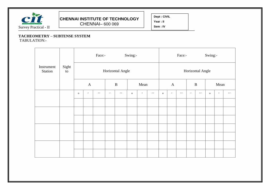
TACHEOMETRY – SUBTENSE SYSTEM
TABULATION:-
Instrument
Station
Sight
to
Face:- Swing:- Face:- Swing:-
Horizontal Angle Horizontal Angle
A B Mean A B Mean
° ´ ´´ ´ ´´ ° ´ ´´ ° ´ ´´ ´ ´´ ° ´ ´´

Survey Practical - II
CHENNAI INSTITUTE OF TECHNOLOGY
CHENNAI– 600 069
Dept : CIVIL
Year : II
Sem : IV
Calculation:
Survey Practical - II
CHENNAI INSTITUTE OF TECHNOLOGY
CHENNAI– 600 069
Dept : CIVIL
Year : II
Sem : IV
RESULT:
Horizontal distance between O and the Subtense bar =
MARKS out of 10: Signature of the staff in-charge

Survey Practical - II
CHENNAI INSTITUTE OF TECHNOLOGY
CHENNAI– 600 069
Dept : CIVIL
Year : II
Sem : IV
AB,BC, etc - centre line
1-2,2-3,etc. - Excavation line
L,M,N ,etc - Masonry pillars

Survey Practical - II
CHENNAI INSTITUTE OF TECHNOLOGY
CHENNAI– 600 069
Dept : CIVIL
Year : II
Sem : IV
Expt No.12 SETTING OUT WORKS - FOUNDATION MARKING. Date: --------------
AIM
To set out the foundation marking for the proposed construction of building.
APPARATUS USED
1.Theodolite, 2. Chain (or) Tape 3.Ranging rods, 3. Pegs or Arrows, 4. String.
GENERAL
The operation of the marking on the site the centre lines of the foundation of a building is called
setting out. Setting out of a foundation is the first step in the construction of any structure.
PROCEDURE
1. A centre line sketch of the building is prepared. (The centres of cross walls are also to be indicated.)
2. The base line is set out with reference to given reference points.
3. The ends of the centre line of the walls, points A and B from the base line are marked.
4. As the end marks A,B,C,etc. are disturbed during excavation, stakes are fixed at L,M,N etc., a little
away (about 2 to 3 m) for end mark and tied accurately using a string.
5. The centre line for all other walls AD,BC,etc are marked by dropping perpendicular. For small
buildings the perpendiculars may be set out by using a chain or a tape by ‘3-4-5’ method. For an
important and big building when sides are long a Theodolite may be employed to accurately set out the
perpendiculars and to range the lines.
6. For every wall, the pegs are driven a little away for marking the end and tied accurately using a string.
7. Diagonals are measured and checked with their corresponding calculated lengths.
8. Width of foundation from the centerline are marked and the corners 1,2,3,4,5 etc., are fix up. Pegs are
driven at these corners. The cord is stretched and lime is spread along the chords.
RESULT:
Thus the trench plan being marked on the ground, and excavation may be started.
MARKS out of 10: Signature of the staff in-charge

Survey Practical - II
CHENNAI INSTITUTE OF TECHNOLOGY
CHENNAI– 600 069
Dept : CIVIL
Year : II
Sem : IV
Survey Practical - II
CHENNAI INSTITUTE OF TECHNOLOGY
CHENNAI– 600 069
Dept : CIVIL
Year : II
Sem : IV
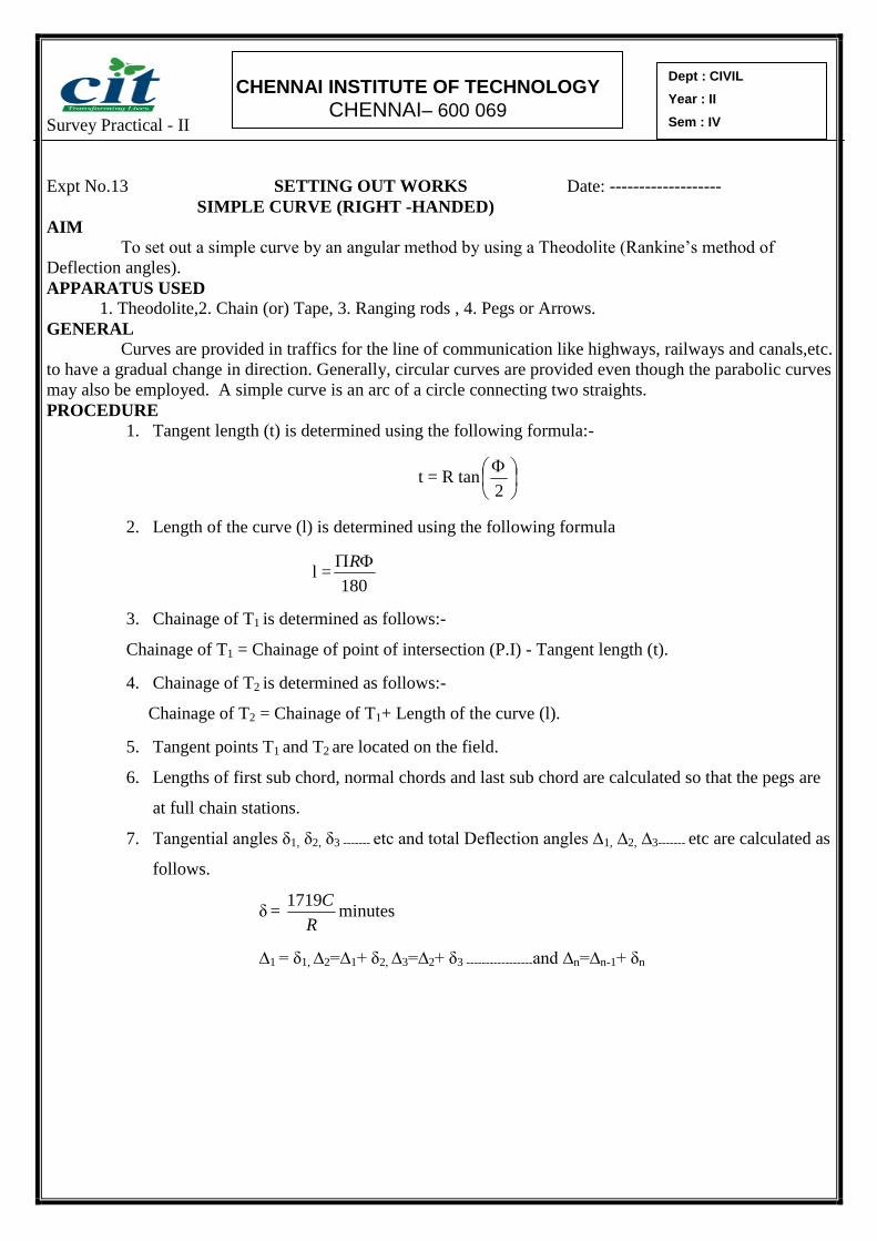
Expt No.13 SETTING OUT WORKS Date: -------------------
SIMPLE CURVE (RIGHT -HANDED)
AIM
To set out a simple curve by an angular method by using a Theodolite (Rankine’s method of
Deflection angles).
APPARATUS USED
1. Theodolite,2. Chain (or) Tape, 3. Ranging rods , 4. Pegs or Arrows.
GENERAL
Curves are provided in traffics for the line of communication like highways, railways and canals,etc.
to have a gradual change in direction. Generally, circular curves are provided even though the parabolic curves
may also be employed. A simple curve is an arc of a circle connecting two straights.
PROCEDURE
1. Tangent length (t) is determined using the following formula:-
t = R tan
2
2. Length of the curve (l) is determined using the following formula
l =180
R
3. Chainage of T1 is determined as follows:-
Chainage of T1 = Chainage of point of intersection (P.I) - Tangent length (t).
4. Chainage of T2 is determined as follows:-
Chainage of T2 = Chainage of T1+ Length of the curve (l).
5. Tangent points T1 and T2 are located on the field.
6. Lengths of first sub chord, normal chords and last sub chord are calculated so that the pegs are
at full chain stations.
7. Tangential angles δ1, δ2, δ3 ------- etc and total Deflection angles ∆1, ∆2, ∆3------- etc are calculated as
follows.
δ = R
C1719minutes
∆1 = δ1, ∆2=∆1+ δ2, ∆3=∆2+ δ3 -----------------and ∆n=∆n-1+ δn

Survey Practical - II
CHENNAI INSTITUTE OF TECHNOLOGY
CHENNAI– 600 069
Dept : CIVIL
Year : II
Sem : IV
Calculation:

Survey Practical - II
CHENNAI INSTITUTE OF TECHNOLOGY
CHENNAI– 600 069
Dept : CIVIL
Year : II
Sem : IV
Note: - The total deflection angle ∆n= Ф/2 Where, Ф is the deflection angle of the curve or central
angle of the curve.
8. Theodolite is set up at the point of curve T1 and levelled.
9. Vernier A is set to zero and upper clamp is clamped. Lower clamp is loosened and intersection point B
is bisected exactly using the lower tangent screw. Thus the line of sight is maintained in the direction of
T1B and the vernier A kept zero.
10. Upper clamp is loosened and the deflection angle ∆1 is set at vernier A.The line of collimation is now
directed along the chord T1D, and the upper clamp is clamped.
11. Zero end of the Tape is held at T1and an arrow is placed at a distance equal to first chord length of T1D
= C1 on the tape. Tape is swung around T1 till the arrow is bisected by the line of sight. Thus the first
point D is established on the curve. First peg is fixed at D.
12. Upper clamp is loosened and the deflection angle ∆2 is set at vernier A.The line of collimation is now
directed along the chord T1E, and the upper clamp is clamped.
13. Zero end of the Tape is held at D and an arrow is placed at a distance equal to second chord length of
DE = C2 = C on the tape. Tape is swung around D till the arrow is bisected by the line of sight. Thus the
first point E is established on the curve. Second peg is fixed at E.
14. The same procedure is repeated till the last point is reached. As a check, the location of last point is
verified whether it coincide the tangent point T2 fixed already from the P.I or not.
Note:-
In the case of left handed curves, the vernier should be set to (360°-∆1), (360°-∆2), (360°-∆3) etc to
obtain successive points on the curve after sighting the intersecting point with both the plates clamped
at zero.
RESULT:
Thus the simple curve is set using Rankine’s method of Deflection angles.
MARKS out of 10: Signature of the staff in-charge

Survey Practical - II
CHENNAI INSTITUTE OF TECHNOLOGY
CHENNAI– 600 069
Dept : CIVIL
Year : II
Sem : IV
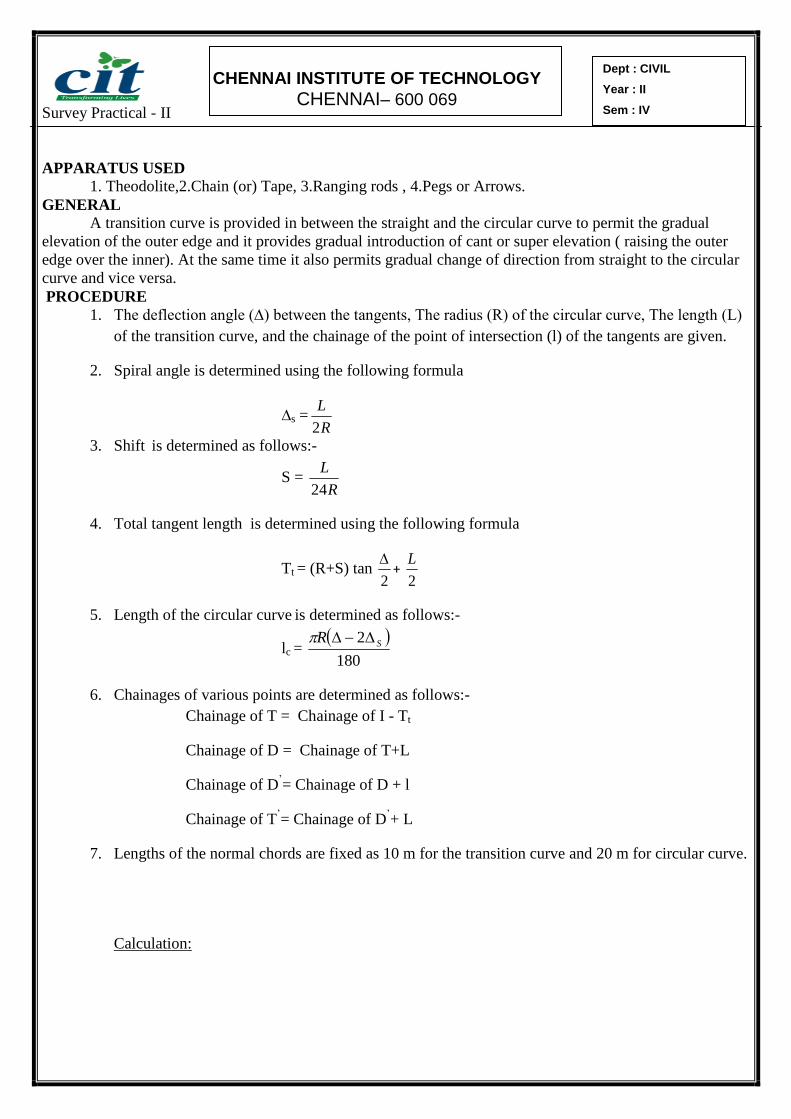
Expt No.14 SETTING OUT WORKS – TRANSITION CURVE Date: ---------------
AIM
To set out a Transition curve by using a Theodolite.
Survey Practical - II
CHENNAI INSTITUTE OF TECHNOLOGY
CHENNAI– 600 069
Dept : CIVIL
Year : II
Sem : IV
APPARATUS USED
1. Theodolite,2.Chain (or) Tape, 3.Ranging rods , 4.Pegs or Arrows.
GENERAL
A transition curve is provided in between the straight and the circular curve to permit the gradual
elevation of the outer edge and it provides gradual introduction of cant or super elevation ( raising the outer
edge over the inner). At the same time it also permits gradual change of direction from straight to the circular
curve and vice versa.
PROCEDURE
1. The deflection angle (∆) between the tangents, The radius (R) of the circular curve, The length (L)
of the transition curve, and the chainage of the point of intersection (l) of the tangents are given.
2. Spiral angle is determined using the following formula
∆s =R
L
2
3. Shift is determined as follows:-
S = R
L
24
4. Total tangent length is determined using the following formula
Tt = (R+S) tan 2
+
2
L
5. Length of the circular curve is determined as follows:-
lc =
180
2 SR
6. Chainages of various points are determined as follows:-
Chainage of T = Chainage of I - Tt
Chainage of D = Chainage of T+L
Chainage of D’= Chainage of D + l
Chainage of T’= Chainage of D
’+ L
7. Lengths of the normal chords are fixed as 10 m for the transition curve and 20 m for circular curve.
Calculation:

Survey Practical - II
CHENNAI INSTITUTE OF TECHNOLOGY
CHENNAI– 600 069
Dept : CIVIL
Year : II
Sem : IV
8. Lengths of the sub chords are calculated after knowing the chainages of salient points.
9. Deflection angles for transition curve are determined as follows:-

Survey Practical - II
CHENNAI INSTITUTE OF TECHNOLOGY
CHENNAI– 600 069
Dept : CIVIL
Year : II
Sem : IV
α = RL
l
21800minutes
l is measured from the tangent point T. The deflection angle at the junction of the transition curve
and the circular curve for l = L, is
αn =R
L
1800 As a check, αn should be equal to
3
3
For circular curve the deflection angles are determined from the formula
δ = R
C1719minutes
Where C is the length of the chord, and δ is the tangential angles from the tangent at D.
10. Total Deflection angles ∆1, ∆2, ∆3------- etc are calculated as follows.
∆1 = δ1, ∆2=∆1+ δ2, ∆3=∆2+ δ3 -----------------and ∆n=∆n-1+ δn
As a check, ∆n should be equal to s 22
1
11. Tangent point (T) is located by determining its chainage from the point of intersection (I).Similarly
the other tangent point (T’) is located by measuring the total tangent length(Tt) along the forward
tangent length from P.I.
12. A theodolite is set up at T, the vernier A is set to zero and I is bisected. The points on the transition
curve are located from the computed deflection angles for the first sub-chord and normal chords.
13. The last deflection angles for the transition curve should be equal to 3
s and the perpendicular
offset from the tangent TI, should be equal to 4S. The distance to each of the successive points on
the transition curve is measured from T.
14. Having laid the transition curve, the theodolite is shifted to D. after setting up and leveling the
vernier set to read the angle (360°- s3
2) for a right-hand curve and s
3
2 for a left-hand curve.
15. Back sight is taken on T and the telescope is rotated in azimuth by an angle s3
2 till zero reading is
obtained on the circle. In this position the telescope is directed along DD1. On transiting the
telescope, the line of sight is directed along the tangent D1D with reference to which the deflection
angles of the circular curve have been calculated.

Survey Practical - II
CHENNAI INSTITUTE OF TECHNOLOGY
CHENNAI– 600 069
Dept : CIVIL
Year : II
Sem : IV
16. After the orientation of line of sight the reading on the circle is zero. The vernier is set to the
calculated deflection angles for the circular curve and the points on it are located in usual way.
For the last point D’ of the circular curve, the last deflection angle must be equal to s 22
1.
17. The other transition curve is set out from T’ in the similar manner as the first is set out from T. the
point D’ set out from T’ must be the same as already set out from D.

Survey Practical - II
CHENNAI INSTITUTE OF TECHNOLOGY
CHENNAI– 600 069
Dept : CIVIL
Year : II
Sem : IV
RESULT:
Thus the transition curve is set using the theodolite with the method of Deflection angles.
MARKS out of 10: Signature of the staff in-charge

Survey Practical - II
CHENNAI INSTITUTE OF TECHNOLOGY
CHENNAI– 600 069
Dept : CIVIL
Year : II
Sem : IV
Expt No.15 AZIMUTH BY THE EX-MERIDIAN OBSERVATION ON THE SUN Date: ---------------
Aim :
To find the angle between the observes meridian and the vertical circle through the body.
General :
The required altitude and the horizontal angles are those to the sun’s centre. Hence the hairs should be set
tangential to the two limbs simultaneously. The opposite limbs are then observed by changing the face as
shown in figure.
Procedure :
1. Set the instrument over the station mark and leveling very accurately.
2. Clamp both the plates to zero and sight the reference mark (RM).
3. Turn to the sun and observe and altitude and horizontal angle with the sun in quadrant 1 of the
cross hair system.
The motion in the azimuth is slow and the vertical hair is kept in contact by the upper tangent
screw, the sun being allowed to make contact with the horizontal hair the line of observation is
also noted.
4. Using two tangential screw as quickly as possible, bring the sun in to the quadrant 3 of the cross
hairs and again read the horizontal and vertical angles. Observe also the chronometer time.
5. Turn the RM. Reverse the face and take another side to RM.
6. Take two more observations of the sun precisely in the same way as in steps 3 and 4 above, but
this time with the sun is quadrant 2 and 4. Note the time of each observations.
7. Finally bisect the RM to see that the reading is zero.
During the above four observations (two with face left and two with face right)

Survey Practical - II
CHENNAI INSTITUTE OF TECHNOLOGY
CHENNAI– 600 069
Dept : CIVIL
Year : II
Sem : IV
Calculation:
Survey Practical - II
CHENNAI INSTITUTE OF TECHNOLOGY
CHENNAI– 600 069
Dept : CIVIL
Year : II
Sem : IV
Result :
Azimuth of the given line =
MARKS out of 10: Signature of the staff in-charge

Survey Practical - II
CHENNAI INSTITUTE OF TECHNOLOGY
CHENNAI– 600 069
Dept : CIVIL
Year : II
Sem : IV
Survey Practical - II
CHENNAI INSTITUTE OF TECHNOLOGY
CHENNAI– 600 069
Dept : CIVIL
Year : II
Sem : IV
Expt No.16 Study of Total Station Date: ---------------
General:
Total station is a combination of Electronic Theodolite and Electronic Distance Meter (EDM) in one unit.
This instrument directly measures 3D co-ordinates, slope, horizontal and vertical distances. This has large
internal memory of 3000 points to store field datas and can be directly down loaded to the computer from the
instrument through interface cable.
Electronic Distance Meter:
This is used to measure directly, to an acceptable accuracy, the distance between any tow intervisible
points in the survey system. The technique of EDM eliminates the need for chaining or taping.
Principle of EDM:
The basic principle is the indirect determination of the time required for a light beam to travel between two
stations and by using frequency the distance is displayed .
Basic Functions of EDM:
1. It generates the carrier and measuring wave frequencies.
2. It modulates and demodulates the carrier wave.
3. It measures the phase difference between the transmitted and received waves.
4. It displays the result of measurement.
Result:
Thus the study about the Total station is practiced.
MARKS out of 10: Signature of the staff in-charge