department of applied physics, tokyo university of
TRANSCRIPT
arX
iv:2
105.
0618
1v2
[ph
ysic
s.op
tics]
12
Oct
202
1
Characterization of a double torsion pendulum used to detect spin-induced torque
based on Beth’s experiment
Runa Yasuda and Atsushi Hatakeyamaa)
Department of Applied Physics, Tokyo University of Agriculture and Technology, Koganei,
Tokyo 184-8588, Japan
(Dated: 14 October 2021)
We characterized a double torsion pendulum system, including measurements of the
photon-spin-induced torque. Our experimental strategy was similar to that used in Beth’s
experiment, which was performed in 1936 to measure photon-spin-induced torque using
forced oscillation caused by polarization modulation of light incident on a suspended ob-
ject. Through simple passive isolation of the suspended object from external vibration
noise, the achieved torque sensitivity was 2×10⁻¹⁷ N m in a measurement time of 104 s,
which is close to the thermal noise limit and one order smaller than the minimum torque
measured in Beth’s experiment. The observed spin-induced torque exerted on the light-
absorbing optics is consistent with the angular momentum transfer of h̄ per photon.
a)Electronic mail: [email protected]
1

I. INTRODUCTION
The torsion pendulum, or torsion balance, is a sensitive device used to detect weak forces.1 It
was used in the experiments of Cavendish and Coulomb, conducted in the 18th century to measure
gravitational and electrostatic constants. The torsion pendulum is still one of the most sensitive
measurement methods in modern physics and engineering, with applications ranging from low-
frequency gravitational wave detection2 to studies of the mechanical properties of materials.3
The torsion pendulum has been used to detect small mechanical torques exerted on macro-
scopic objects from quantum mechanical spins. The first experiment was performed in 1915 by
Einstein and de Haas,4 who demonstrated that the mechanical rotation of a ferromagnetic material
is caused by flipping of its magnetization or internal atomic spins. The second experiment, by
Beth, was carried out in 19365 and demonstrated that flipping the photon spin from +h̄ to −h̄
(h̄: Planck’s constant divided by 2π) induced the rotation of a transmitting half-wave plate. The
results of both experiments are understood in terms of angular momentum conservation of the sys-
tem of atomic or photonic spins, and the rotation of the macroscopic object. Spin-induced torque
has received renewed attention in recent spintronics and optomechanics studies. Angular momen-
tum transmission due to a spin wave has been mechanically detected with an yttrium ion garnet
cantilever.6 Gigahertz rotation of optically levitated nanoparticles has been demonstrated via spin
transfer arising from circularly polarized trapping light.7,8
In our previous report,9 we discussed the development of a torsion pendulum to study spin
transfer from an optically spin-polarized atomic gas to a solid gas container through atom-surface
interactions. The experiment was similar to that of Beth, in which an object suspended with
a thin wire was irradiated from the bottom with circularly polarized light. Beth’s experiment
has been described in many textbooks.10,11 However, to our knowledge, the careful and patient
measurements conducted therein have not been replicated using the original forced oscillation
method, partly due to experimental difficulties including radiation pressure torque and the so-
called radiometer effects, as well as the multiple steps involved in deriving the torque from the
measured amplitude of the forced oscillation, as pointed out in Ref.12,13. In Ref.12, the authors
directly measured photon-spin-induced torque on the order of 10−12 N m from the acceleration of
a suspended half-wave plate with a high-power infrared laser.
In this study, we analyzed our developed pendulum system, including measurement of the
photon-spin-induced torque. Our experimental strategy was similar to the strategy applied in
2

Beth’s experiment: forced torsional oscillation induced by periodic application of external torque
at the resonance frequency of the pendulum. The main differences between our system and that of
Beth’s study are the use of a double pendulum, in which the first pendulum works as a vibration
isolator, and a higher operating frequency of 0.1 Hz relative to 0.002 Hz in Beth’s experiment.
Through this simple passive isolation from external vibration noise, the torque sensitivity was
2×10⁻¹⁷ N m (in 104 -s measurement time), which is close to the thermal noise limit and one or-
der smaller than the minimum torque measured in Beth’s experiment. The observed spin-induced
torque exerted on the light-absorbing optics is consistent with the angular momentum transfer of
h̄ in the direction of light propagation per photon for left-circularly polarized light.10,14 Therefore,
we concluded that our torsion pendulum properly detected the photon-spin-induced torque.
This paper is organized as follows. We first explain the experimental apparatus, with special
attention given to the design of the double pendulum in Sec. II. In Sec. III, we describe the ex-
perimental procedure, including a forced torsional oscillation approach and a lock-in data analysis
method. We then present our experimental results in Sec. IV, in which measurement of photon-
spin-induced torque and estimation of the torque sensitivity are discussed. The paper is concluded
in Sec. V.
II. EXPERIMENTAL APPARATUS
The experimental apparatus, shown in Fig. 1, is a slightly modified version of our previously
reported one.9 The double torsion pendulum, discussed in detail below, was suspended in a vacuum
chamber fixed on an optical table. The pressure inside was maintained at 1×10⁻⁵ Pa with an ion
pump, which was lower than the radiation pressure exerted on a suspended object by a typical
torque laser beam used in the experiment (1× 10⁻⁴ Pa for a laser intensity of 3× 10⁴ W/m2).
Thus, the radiometer effect from the background gas was negligible.
The angle of the suspended object (“optics holder”) was monitored using an optical lever
method with a red probe laser (CPS650F; Thorlabs Inc.) and a position-sensitive detector (PSD)
(S3932; Hamamatsu Photonics K.K.) located L = 0.38 m from the torsional axis. The angle dis-
placement dφ was derived from the position displacement dx measured with the PSD as dφ =
dx/(2L). Light from the torque laser, a volume-holographic-grating-stabilized laser with a wave-
length of 852 nm (LD852-SEV600; Thorlabs Inc.), was incident on the object from the bottom.
The light polarization was controlled with a set of waveplates, including a liquid crystal variable
3
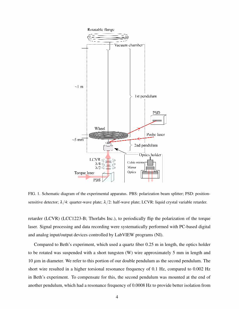
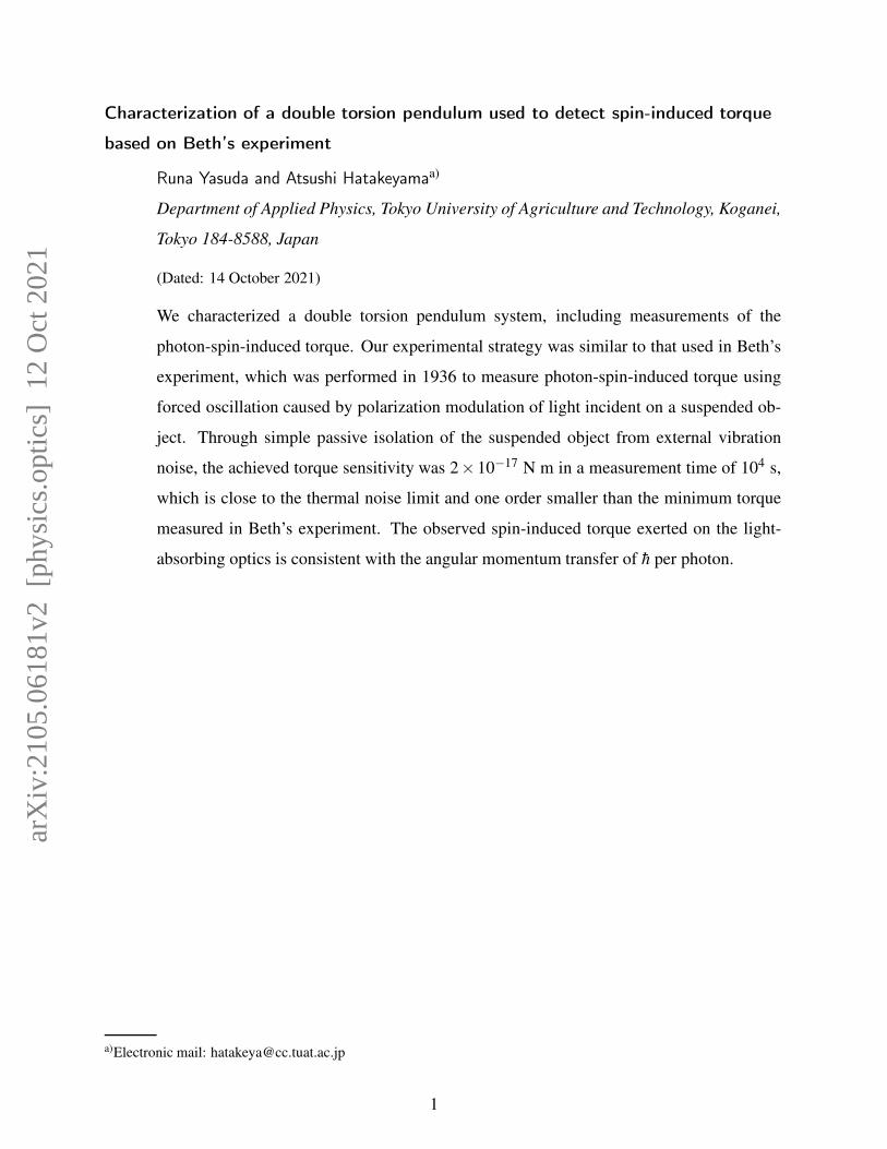
FIG. 1. Schematic diagram of the experimental apparatus. PBS: polarization beam splitter; PSD: position-
sensitive detector; λ/4: quarter-wave plate; λ/2: half-wave plate; LCVR: liquid crystal variable retarder.
retarder (LCVR) (LCC1223-B; Thorlabs Inc.), to periodically flip the polarization of the torque
laser. Signal processing and data recording were systematically performed with PC-based digital
and analog input/output devices controlled by LabVIEW programs (NI).
Compared to Beth’s experiment, which used a quartz fiber 0.25 m in length, the optics holder
to be rotated was suspended with a short tungsten (W) wire approximately 5 mm in length and
10 µm in diameter. We refer to this portion of our double pendulum as the second pendulum. The
short wire resulted in a higher torsional resonance frequency of 0.1 Hz, compared to 0.002 Hz
in Beth’s experiment. To compensate for this, the second pendulum was mounted at the end of
another pendulum, which had a resonance frequency of 0.0008 Hz to provide better isolation from
4
external vibration noise, as discussed below. The higher resonance frequency also provided shorter
measurement times, which minimized spurious effects of drifting. The optics holder accommo-
dated half-inch optics, on which torque was exerted from the torque laser beam; a mirror reflected
the torque laser beam when it transmitted the optics. A cubic mirror was attached to the top of
the optics holder for the optical lever. The moment of inertia of the optics holder was estimated to
be (9.4±0.9)×10−8 kg m2 from the drawing. The uncertainty originated from inaccuracy in the
manufacturing process; it was estimated by comparing the designed and measured weights of the
optics holder.
The optics holder suspended with the short wire was attached to another torsion pendulum (the
first pendulum), which consisted of an object (the “wheel”) with a large moment of inertia and
a long wire. The moment of inertia of the wheel was estimated to be 7× 10⁻⁶ kg m2, and the
W wire was approximately 1 m in length and 10 µm in diameter. The first pendulum had a low
resonance frequency of torsional oscillation at 0.0008 Hz and served as a vibration isolator for the
second pendulum, as discussed below.
The long wire was attached to a vacuum chamber flange (VRS-70M; Shinku-Kogaku Corp.),
which was rotatable with an electric stepper motor (0.00004◦/pulse). This rotatable flange was
used to dampen the torsional oscillation of the first pendulum. Figure 2 shows the angle of the
rotatable flange controlled electronically, as well as the angle of the optics holder measured with
the optical lever. The curve representing the angle of the optics holder was low-pass-filtered to
clarify the oscillation of the first pendulum at its resonance period (1240 s). At 0 s in Fig. 2,
proportional integral control to the flange angle was activated toward the target angle of 0 mrad
for the optics holder to dampen the resonance oscillation of the first pendulum. This damping
technique was quite useful for readying the system for forced oscillation measurements for the
second pendulum, after the apparatus experienced large external perturbations such as earthquakes,
which often caused large and slowly damping torsional oscillation of the first pendulum.
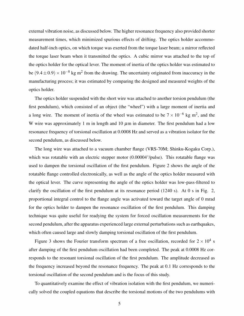
Figure 3 shows the Fourier transform spectrum of a free oscillation, recorded for 2× 10⁴ s
after damping of the first pendulum oscillation had been completed. The peak at 0.0008 Hz cor-
responds to the resonant torsional oscillation of the first pendulum. The amplitude decreased as
the frequency increased beyond the resonance frequency. The peak at 0.1 Hz corresponds to the
torsional oscillation of the second pendulum and is the focus of this study.
To quantitatively examine the effect of vibration isolation with the first pendulum, we numeri-
cally solved the coupled equations that describe the torsional motions of the two pendulums with
5

!
"
#
$
#
"
%&'()
*+,
-./0
1$$$$2$$$!$$$"$$$#$$$$ #$$$
34,)*+50
*678495*:;(/)-*<;8.8.=()*>(.&')
FIG. 2. Damping of the torsional oscillation of the first pendulum with the rotatable flange. The angle of
the rotatable flange was controlled electronically, while the angle of the optics holder was measured with
the optical lever. The curve representing the angle of the optics holder was low-pass-filtered to clarify the
oscillation of the first pendulum at its resonance period (1240 s). At 0 s, the automatic proportional integral
control to the flange angle was activated toward the target angle of 0 mrad for the optics holder.
!" #
!" $
!" %
!" &
!"
!" !
!"'
!"(
!")
!"*
!"#
!"$
+,-./012.34567-1028./9:2-;67<=
!:!!! !:!! !:! !:
>/0,-0;?@28AB=
2C0.<-/012<40?7/-32DE-950240;1-5-32<63-5.76E;2+6;F50240;1-5-32<63-5.76E;
FIG. 3. Fourier transform spectrum of free torsional oscillation of the pendulum for 2×10⁴-s measurement.
Numerical simulations for the double and single pendulums are also shown.
application of white noise between 0 and 2 Hz to the fixed end of the first pendulum wire; the
freedom of motion in the simulation was the rotation of the first and second pendulums around
the fixed wire axis. With appropriate experimental parameters, as shown in Fig. 3, the Fourier
transform spectrum of the simulation reproduced the experimental observations fairly well, par-
ticularly the decrease in baseline oscillation amplitude at higher frequencies than the resonance
of the first pendulum. The effect of vibration isolation can be clearly understood by comparing
the measured spectrum with the single pendulum simulation performed on the assumption that the
second pendulum was attached directly to the flange without the first pendulum.
6

III. EXPERIMENTS
We adopted a forced oscillation method at the resonance frequency of the second pendulum.
A numerical simulation using the coupled equations for the double pendulum confirmed that the
second pendulum could be regarded as a single pendulum around its resonance frequency, while
the first pendulum (to which the second pendulum was attached) oscillated at a much lower res-
onance frequency. Therefore, we can use basic knowledge regarding the forced oscillation of the
single pendulum, as described below.
In a steady state, the frequency dependence of the quadrature component of the forced os-
cillation with respect to the periodic external torque N′ cosωt (ω: angular frequency; t: time)
corresponded to the following Lorentzian function around the resonance frequency:
µN′
4IωR
1
(ω −ωR)2 +(µ/2)2, (1)
where I is the moment of inertia, ωR is the resonance angular frequency, and µ is the full width
at half maximum of the resonance, determined by friction proportional to the angular velocity.
Therefore, the peak amplitude of the resonance A is N′/(µIωR). The torque modulation N′ was
then derived from the quadrature component of the torsional oscillation at the resonance, as fol-
lows:
N′ = µIωRA =Iω2
RA
Q, (2)
where Q = ωR/µ is the Q-factor of the resonance.
In this study, the optical torque dependent on the photon spin was modulated in a square wave
by changing the torque laser polarization with the LCVR, rather than in a sinusoidal wave. Ac-
cording to the Fourier expansion, ±N square modulation in the torque corresponds to N′ = 4π N
sinusoidal modulation. Therefore, the factor 4/π was considered when deriving the torque modu-
lation N from the measured quadrature component as follows:
N =π
4µIωRA =
π
4
Iω2RA
Q. (3)
We evaluated ωR and Q in every set of measurements to derive N from the measured A.
The quadrature and in-phase components of the oscillation (i.e., the oscillation amplitude and
phase delay with respect to the reference signal, which was synchronized with the modulation of
the torque laser polarization) were derived by lock-in analysis of the forced oscillation using Igor
Pro data analysis software (WaveMetrics, Inc.).
7
The spin-induced torque modulated by flipping the polarization of the torque laser between the
left- and right- circular polarizations is Plaserλ/(2πc) = Plaser[W ]×4.52×10⁻¹⁶ N m, where Plaser
and λ are the power and the wavelength of the torque laser, respectively, and c is the speed of
light, because one photon carries +h̄ or −h̄ spin component along the laser propagation. Special
precautions were required against torque caused by radiation pressure. The torque exerted on the
optics by the radiation pressure of the torque laser beam Nrad can be calculated by the following
equation:
Nrad = r×Frad, (4)
where r is the position at the laser beam enters the optics with respect to the wire-fixed position,
and Frad is the radiation force. If the torque laser beam is incident either perfectly parallel to
or onto the wire-fixed point, the torque around the rotation axis is zero. Assuming imperfect
incidence of the torque laser with a deviation of a and an incline of α from the rotation axis,
the torque around the rotation axis is α|Frad|a = αPlasera/c. When we measure optical torque in
polarization modulation mode, the ratio of modulation of the radiation pressure torque to that of
the spin-induced torque is 2π(a/λ )αβ , where β is a factor representing the modulation of the
radiation pressure torque. This modulation may have been caused by variation in the laser power.
Careful adjustment of the optical system to minimize the imperfect incidence and power variation
associated with the polarization modulation is required to make the factor 2π(a/λ )αβ much less
than 1, such that the spin-induced torque modulation dominated the radiation pressure torque
modulation. It was not difficult to fulfill this requirement, assuming a = 1 mm, α = 10−2 rad,
and β = 10−3 for λ = 852 nm. The effect of radiation pressure was examined by intentionally
modulating the power of the torque laser in the experiment.
IV. RESULTS
Because the optics holder was able to accommodate various types of half-inch optics, we ex-
amined several optics. We mainly focused on a neutral density (ND) filter (NE560B-B; Thorlabs
Inc.) as a light absorber, because our future target, a solid container of an atomic gas, can be
regarded as a light absorber.9 The absorption of the torque light by the ND filter was greater than
99.9%. The spatial mode of the laser beam was filtered to be TEM00 with a single-mode fiber.
The laser power incident on the ND filter was 132 mW. The polarization of the torque laser was
modulated between left-circular and right-circular polarization using the LCVR.
8
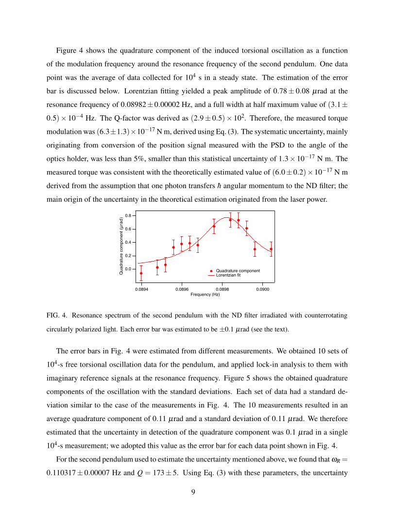
Figure 4 shows the quadrature component of the induced torsional oscillation as a function
of the modulation frequency around the resonance frequency of the second pendulum. One data
point was the average of data collected for 104 s in a steady state. The estimation of the error
bar is discussed below. Lorentzian fitting yielded a peak amplitude of 0.78± 0.08 µrad at the
resonance frequency of 0.08982±0.00002 Hz, and a full width at half maximum value of (3.1±
0.5)× 10−4 Hz. The Q-factor was derived as (2.9± 0.5)× 102. Therefore, the measured torque
modulation was (6.3±1.3)×10−17 N m, derived using Eq. (3). The systematic uncertainty, mainly
originating from conversion of the position signal measured with the PSD to the angle of the
optics holder, was less than 5%, smaller than this statistical uncertainty of 1.3×10⁻¹⁷ N m. The
measured torque was consistent with the theoretically estimated value of (6.0±0.2)×10−17 N m
derived from the assumption that one photon transfers h̄ angular momentum to the ND filter; the
main origin of the uncertainty in the theoretical estimation originated from the laser power.
FIG. 4. Resonance spectrum of the second pendulum with the ND filter irradiated with counterrotating
circularly polarized light. Each error bar was estimated to be ±0.1 µrad (see the text).
The error bars in Fig. 4 were estimated from different measurements. We obtained 10 sets of
104-s free torsional oscillation data for the pendulum, and applied lock-in analysis to them with
imaginary reference signals at the resonance frequency. Figure 5 shows the obtained quadrature
components of the oscillation with the standard deviations. Each set of data had a standard de-
viation similar to the case of the measurements in Fig. 4. The 10 measurements resulted in an
average quadrature component of 0.11 µrad and a standard deviation of 0.11 µrad. We therefore
estimated that the uncertainty in detection of the quadrature component was 0.1 µrad in a single
104-s measurement; we adopted this value as the error bar for each data point shown in Fig. 4.
For the second pendulum used to estimate the uncertainty mentioned above, we found that ωR =
0.110317± 0.00007 Hz and Q = 173± 5. Using Eq. (3) with these parameters, the uncertainty
9

FIG. 5. Fluctuation of quadrature components of the free torsional oscillation. Each error bar represents the
standard deviation for each 104-s measurement.
in the quadrature component detection of 0.1 µrad was converted to the uncertainty in the torque
detection of 2 × 10⁻¹⁷ N m. We regarded this as the torque sensitivity of our system over a
measurement time of 104 s. The thermal noise limit of the torque Nther can be estimated using the
following formula,16
Nther =π
4
√
4kBT IωR
Q∆t, (5)
where kB is the Boltzmann constant, T is temperature, and ∆t is the measurement time. The
estimated thermal noise limit was 2×10⁻¹⁷ N m, which is close to the experimentally estimated
sensitivity.
We also confirmed that the observed oscillation phase was consistent with the expected rota-
tion direction; specifically, left-circularly polarized light carries +h̄ angular momentum along the
direction of propagation10,14 and exerts a positive torque on the ND filter.
To confirm that the observed torque originated from photon spin, rather than from other effects
such as radiation pressure torque, we measured the light polarization dependence. At a fixed mod-
ulation frequency, we changed the polarization modulation by rotating the LCVR axis from a pair
of counterrotating circular polarizations to a pair of counterrotating elliptical polarizations. Fig-
ure 6 shows the measured torque as a function of the spin component along the light propagation
direction. The spin component of 0 h̄ corresponds to nominally unmodulated linear polarization,
whereas the spin component of 1 h̄ corresponds to circular polarizations, with elliptical polariza-
tions between the two extremes. The observed torque is reasonably proportional to the photon spin
component of the propagation direction.
We also modulated the power of the torque laser without changing the polarization, to esti-
mate the torque modulation originating from the radiation pressure; specifically, a ±7% change in
10

!
"
#
$
%&'()*+,-$.-/+012
-3$$3 $3!$3"$3#$3$
!"#$%&'!&(#)#*$+,-$.
+4*5*65*7+5&'()*+89:*;'+<95
FIG. 6. Polarization dependence of the photon-spin-induced torque. Each error bar was estimated to be
±2×10⁻¹⁷ N m (see the text).
power induced a torque modulation of 1×10⁻¹⁶ N m. The power modulation associated with the
polarization change with the LCVR was 0.1%. Therefore, we estimated that the torque modulation
originating from the radiation pressure was 1×10⁻¹⁸ N m, which was negligible in the observed
torque modulation. Taken together, we concluded that the observed torque was induced by photon
spin transfer.
V. CONCLUSIONS
In this paper, we describe the characterization of our developed double torsion pendulum sys-
tem using optical torque with a forced oscillation method similar to Beth’s experiment. In the
double pendulum approach, the first pendulum operates as a vibration isolator. With this simple
passive isolation from external vibration noise, the torque sensitivity reached 2× 10⁻¹⁷ N m in
104 -s measurement time, which is close to the thermal noise limit and one order smaller than the
minimum torque measured in Beth’s experiment. We evaluated the photon-spin-induced torque
using a ND filter as a light absorber. The observed torque was consistent with the torque expected
from the angular momentum transfer of h̄ (or −h̄) per photon in left- (or right-) circularly polarized
light. We concluded that our torsion pendulum properly detected the photon-spin-induced torque.
Our demonstration can be regarded as a recapitulation of Beth’s experiment.
Finally, the developed double pendulum could be used in future detailed studies of spin transfer
from gases to solids.
11
ACKNOWLEDGMENTS
We thank Jean Jeener for his useful comments. This study was supported by the Matsuo Foun-
dation.
DATA AVAILABILITY STATEMENT
The data that support the findings of this study are available from the corresponding author
upon reasonable request.
REFERENCES
1G. T. Gillies and R. C. Ritter, Review of Scientific Instruments 64, 283 (1993).
2T. Shimoda, S. Takano, C. P. Ooi, N. Aritomi, Y. Michimura, M. Ando, and A. Shoda, Interna-
tional Journal of Modern Physics D 29, 1940003 (2020).
3B. Keshavarz, B. Zarket, S. Amin, R. Rughani, S. Muthukrishnan, N. Holten-Andersen, and
G. H. McKinley, Soft Matter 17, 4578 (2021).
4A. Einstein and W. J. de Haas, Koninklijke Akademie van Wetenschappen te Amsterdam, Pro-
ceedings 18 I, 696 (1915).
5R. A. Beth, Phys. Rev. 50, 115 (1936).
6K. Harii, Y.-J. Seo, Y. Tsutsumi, H. Chudo, K. Oyanagi, M. Matsuo, Y. Shiomi, T. Ono,
S. Maekawa, and E. Saitoh, Nature Communications 10, 2616 (2019).
7R. Reimann, M. Doderer, E. Hebestreit, R. Diehl, M. Frimmer, D. Windey, F. Tebbenjohanns,
and L. Novotny, Phys. Rev. Lett. 121, 033602 (2018); Erratum: F. van der Laan, R. Reimann,
M. Doderer, E. Hebestreit, R. Diehl, M. Frimmer, D. Windey, F. Tebbenjohanns, and L. Novotny,
Phys. Rev. Lett. 126, 159901, (2021).
8J. Ahn, Z. Xu, J. Bang, Y.-H. Deng, T. M. Hoang, Q. Han, R.-M. Ma, and T. Li, Phys. Rev. Lett.
121, 033603 (2018).
9A. Hatakeyama, R. Yasuda, Y. Goto, N. Chikakiyo, T. Kuroda, and Y. Nagata, AIP Advances 9,
075002 (2019).
10E. Hecht, Optics, 5th ed. (Pearson, Harlow, 2016).
11B. Bransden and C. Joachain, Physics of Atoms and Molecules (Pearson, Harlow, 2003).
12G. Delannoy, O. Emile, and A. Le Floch, Applied Physics Letters 86, 081109 (2005).
12

13O. Emile and J. Emile, Annalen der Physik 530, 1800111 (2018).
14A. Corney, Atomic and Laser Spectroscopy (Oxford University Press, Oxford, 1977).
15H. Magallanes and E. Brasselet, Nature Photonics 12, 461 (2018).
16L. Haiberger, M. Weingran, and S. Schiller, Review of Scientific Instruments 78, 025101 (2007).
13