department mechanical vibrations of a beam
TRANSCRIPT

H.P. lee Department of Mechanical &
Production Engineering National University of Singapore
10 Kent Ridge Crescent, Singapore 0511
Vibrations of a Beam
Moving Over Supports
with Clearance
The transverse vibration of a beam moving over two supports with clearance is analyzed using Euler beam theory. The equations of motion are formulated based on a Lagrangian approach and the assumed mode method. The supports with clearance are modeled as frictionless supports with piecewise-linear stiffness. A feature of the present formulation is that its complexity does not increase with increased number of supports. Results of numerical simulations are presented for various prescribed motions of the beam. The effect of support clearance on the stability of the beam is investigated. © 1994 John Wiley & Sons, Inc.
INTRODUCTION
The mechanics of a stationary beam acted upon by moving loads have been studied in connection with machining processes and applications in the behavior of railway tracks and bridges under moving loads. The earliest work on the vibration of a beam subjected to a constant moving load was presented by Timoshenko (1922). The effects of elastic foundation, moving mass, and deflection dependent moving loads were included in subsequent studies by Nelson and Conover (1971), Benedetti (1974), Steele (1967), Florence (1965), and Katz et al. (1987). A related problem on the dynamics of a beam of finite length moving over supports was first presented by Buffinton and Kane (1985) using the method of Kane's dynamics. The support was assumed to be perfect without any clearance. The dynamics of a beam moving over supports with clearance has not been reported in the literature.
It is difficult to eliminate clearance at the supports during the manufacturing or construction
Received April 12, 1992; Accepted May 28, 1994
Shock and Vibration, Vol. 1, No.6, pp. 549-557 (1994) © 1994 John Wiley & Sons, Inc.
process. There are numerous studies on the dynamics of mechanical systems with clearances using the model of an impact pair. A list of references can be found in the reported works by Comparin and Singh (1989, 1990). The characteristic of a clearance is often modeled as a spring with piecewise-linear stiffness (Comparin and Singh, 1990; Murakami and Sato, 1990; Dubow sky and Freudenstein, 1971), or a spring with hysteretic stiffness (Maezawa and Watanabe, 1975). The present analysis is an extension of an earlier work (Lee, 1992) for analyzing the dynamics of a beam moving over multiple supports without clearance. The supports in that article were modeled as linear springs with very large stiffness. For the present study, each support with clearance was modeled as a spring with piecewise-linear stiffness. This assumption removes the necessity to compute the normal forces at the supports. Moreover, it will be shown in the formulation that the complexity of the formulation does not increase with an increased number of supports.
CCC 1070-9622/94/060549-09
549

550 Lee
THEORY AND FORMULATIONS
The beam considered is assumed to be a uniform beam of length L moving horizontally over two supports shown in Fig. 1. Horizontal forces are applied at the left end of the beam to pull or push the beam over these supports. An assumption made in the following formulation is that transverse deflections are small so that the dynamic behavior of the beam is governed by Euler beam theory. Moreover, all the transverse deflections and the axial motion of the beam occur in the plane defined by i and j unit vectors fixed in the beam. The unit vectors i, j, and k form a set of mutually perpendicular unit vectors. The origin is located at the left end of the beam. Flexibility of the beam in the axial direction i is assumed to be negligible compared to the lateral direction j.
The position vector of a general point P on the deformed beam is given by
p=xi+wj. (1)
The velocity at the point is
Vp = Vi + wj (2)
where w = dwldt and Vi is the prescribed velocity of the beam at x = 0 as a result of the external applied forces at the left end of the beam. Due to the assumption of axial rigidity and small transverse deflection, V is also the i component of the velocity for every point along the beam.
The kinetic energy T of the beam is
1 lL T = - m (V2 + w2) dx 2 0
(3)
where m is the mass of the beam per unit length. Assuming Euler's beam theory, the elastic
strain energy of the beam due to bending is
(4)
j
L~I!----I~ FIGURE 1 A beam moving over two frictionless supports with clearance.
Force
-------,------~------~------- w(a) -0 o
a a
FIGURE 2 Characteristic model of a support with clearance.
where E and I are the Young's modulus and the central principal second moment of area of the cross section of the beam about the k axis, respectively.
The locations of the two supports are given by x = a and x = b. The deflections of the beam at these supports are denoted by w(a) and web), respectively. These relative locations of the supports change with the motion of the beam. The characteristic of a clearance at the support at x =
a is modeled as a piecewise-linear stiffness shown in Fig. 2. As shown in the figure, the clearance is equal to 28a • A similar model is also assumed for the support at x = b with a clearance of 28b •
For Iw(a)1 < 8a , the potential energy due to the support at x = a is zero. For Iw(a)1 > 8a , the potential energy due to this support is
Similarly, the potential energy due to the support at x = b is equal to zero for Iw(b)1 < ab . For Iw(b)1 > ab , the potential energy due to this support is given by
(6)
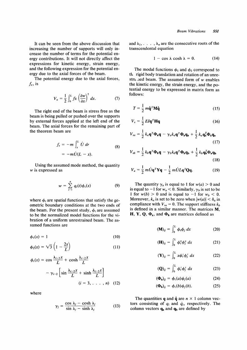
It can be seen from the above discussion that increasing the number of supports will only increase the number of terms for the potential energy contributions. It will not directly affect the expressions for kinetic energy, strain energy, and the following expression for the potential energy due to the axial forces of the beam.
The potential energy due to the axial forces, ix, is
1 (L (aw)2 Va = 2: Jo fx ax dx. (7)
The right end of the beam is stress free as the beam is being pulled or pushed over the supports by external forces applied at the left end of the beam. The axial forces for the remaining part of the theorem beam are
(L . ix = -m Jx U dr (8)
= -mU(L - x).
Using the assumed mode method, the quantity w is expressed as
n
W = L qi(t)cPi(X) (9) i=1
where cPi are spatial functions that satisfy the geometric boundary conditions at the two ends of the beam. For the present study, cPi are assumed to be the normalized model functions for the vibration of a uniform unrestrained beam. The assumed functions are
cPl(X) = 1 (10)
cP2(X) = V3 (1 - ~) (11)
( ) Ai-2X h Ai-2X cPi X = cos ----y;- + cos ----y;-
[ . Ai-2X . h Ai-2X] - 'Y i-2 sm ----y;- + sm ----y;-
(i = 3, . . . ,n) (12)
where
cos A' - cosh A' 'Y'= J J
) sin A.i - sinh A.i (13)
Beam Vibrations 551
and A],. . . ,An are the consecutive roots of the transcendental equation
1 - cos A cosh A = O. (14)
The modal functions cPl and cP2 correspond to th rigid body translation and rotation of an unrestrl> <led beam. The assumed form of w enables the kinetic energy, the strain energy, and the potential energy to be expressed in matrix form as follows:
1 • T • T = 2:mq Mq (15)
1 VB = 2: ElqTHq (16)
V-I k T«I> k T..... 1 T sb - 2: bq bq - 'Yb bq ..... bqb + 2: kbqb<l>aqb
(18)
(19)
The quantity 'Ya is equal to 1 for w(a) > 0 and is equal to -1 for Wa < O. Similarly, 'Y b is set to be 1 for w(b) > 0 and is equal to -1 for Wb < O. Moreover, ka is set to be zero when Iw(a)1 < oa in compliance with Vsa = O. The support stiffness kb is defined in a similar manner. The matrices M, H, Y, Q, «I>a, and «I>b are matrices defined as
(M)ij = J; cPicPj dx (20)
(H)ij = J; cP'f cPJ dx (21)
(Y)ij = J: xcP; cPJ dx (22)
(Q)ij = J; cP; cPJ dx (23)
(<<I>a)ij = cPi(a)cPj(a) (24)
(<<I>b)ij = cPi(b)cPj(b). (25)
The quantities q and it are n x 1 column vectors consisting of qi and qi' respectively. The column vectors qa and qb are defined by

552 Lee
n
aa = L qaiCp;(a) (26) i=[
n
ab = L qbiCPi(b) (27) i=[
where qai and qbi are the i components of qa and qb, respectively.
The matrices M, H, Y, Q, ct-a , and ct-a are symmetric matrices. All the matrices except ct-a
and ct-b are independent oftime. The matrices <l>a and <l>b need to be updated as the beam is moving over the supports.
The Lagrangian of the beam involving wean be expressed as
The linearized Euler-Lagrange equation is
mMq + (EIH + mUY + kact-a + kb<l>b - mULQ)q = 'Yaka<l>aqa + Ybkb<l>bqb. (29)
This equation of motion can be included in numerical integration programs using a fourth-order, variable time step Runge-Kutter method for investigating the response of a beam undergoing various prescribed motions. The magnitudes and signs of w(a) and web) are determined at the beginning of integration for each new time step. The quantities 'Ya, 'Yb, ka, and kb are then assigned suitable values for the subsequent numerical integration.
RESULTS AND SIMULATIONS
Sinusoidal Longitudinal Motions
For the present numerical simulations, L = 1 m, m = 1 kg/m, and EI = 1 N-m2. The beam is assumed to be moving over two supports with a separation of D = 0.25 m. The initial configuration of the beam is such that the two supports are located symmetrically about the center of the beam at a = 0.375 m and b = 0.625 m. The initial shape of the beam is described by
(30)
The values of q[ and q2 are determined from the conditions that w = 0 m for both supports at a = 0.375 m and b = 0.625 m, and w = 0.01 mat x = 0 m and at x = 1 m. Because CPt corresponds
to the rigid body translation, the initial shape of the beam is the first symmetric flexural mode shape of an unrestrained beam passing through the two supports.
For a prescribed longitudinal sinusoidal motion of the beam, the variation of a is assumed to be
a = 0.375 - A sin Ot m. (31)
It was found that the tip displacements for a six-term approximation for ware approximately the same as the tip displacements for a seventerm approximation for w. Consequently, n in Eqs. (26) and (27) is set to be 6 for the following numerical simulations.
The two supports are assumed to be identical having the same clearance with aa = ab = a and ka = kb = k. The clearances aa and ab are expressed as
aa = qa[CP[
ab = qb[ CPI
because CPI = 1, qal = qbl = a.
(32)
(33)
The effect of varying the value of k is examined in Fig. 3 with a = 100 /Lm, A = 0.05, and o = 20 rad/s. It can be seen in Fig. 3 that the tip displacements at the two ends of the beam are relatively insensitive to the variation in k for k > 106 N m- I • The displacements at the supports vary dramatically with the variation in k. For k = 105 N m -1, the maximum displacement at the supports are about twice the magnitude of a. For k 2: 106 N m- I , the maximum tip displacement at the supports is close to the value of a. The support stiffness k is set to be 106 N m- I for the subsequent numerical simulations.
The tip displacement at the left end of the beam and the displacement at the left support for o = 10, 20, and 22 rad/s for A = 0.05 are shown in Figs. 4-6, respectively. The beam shows a stable behavior for 0 = 10 rad/s and unstable behaviors for 0 = 20 and 22 rad/s, which is the same as the behaviors of the beam undergoing the same prescribed longitudinal motion presented by Buffinton and Kane (1985) for supports without any clearance. For 0 = 10 rad/s, shown in Fig. 4, a larger clearance at the supports does not result in a larger amplitude of oscillations at the tip. A slightly longer period of tip oscillation is observed with increased magnitude of clearance. For 0 = 20 rad/s shown in Fig. 5, the

Beam Vibrations 553
IS
S 10
~ 5 0 II ><
° 0;
~ -5
-10
° 0.5 1.5 2 2.5 3 3.5 4
0.04
I Som .';ii~ ~
'" II >< OJ
-0.04
° 0.5 1.5 2 2.5 3 3.5 4
-0.020~----::-'0.-5 --~--1.L..5---2-'-------'2.'-5--~3---3~.5-----l4
0.02 .------;,-----,-------.---,------.,----~--~-~
som ~
W ° >< 0;
~ -0.01
-0.020L--~O.-5 --~--1.L..5---2-'-----2.'-5--~3---3~.5--~4
time (sec)
FIGURE 3 Displacements for a beam moving over supports: n = 20 rad/s; A = 0.05; (-) k = 107 N m- I ; (---) k = 106 N m- I ; ( ••. ) k = 105 N m- I .
variation in the magnitude of the clearance does not change the unstable behavior of the beam. A larger clearance is found to result in a slower rate of increase of the amplitudes of tip displacements. However, for n = 22 radls shown in Fig. 6, a larger clearance seems to lead to an increase in the amplitudes of the tip displacements. Numerical results for n = 20 rad/s and A = 0.025 is shown in Fig. 7. The stable behaviors are consistent with the reported results by Buffinton and Kane (1985).
As has been shown, longitudinal excitation can lead to either stable or unstable transverse motions of the beam. A detailed discussion of this phenomenon can be found in Buffinton and Kane (1985). As explained in their work, the main cause of the transverse motions is that longitudinal motions give rise to transverse inertia forces that grow in magnitude as longitudinal acceleration increases. A detailed stability analysis can be performed by the method presented by Buffinton and Kane (1985) using Floquet's the-

554 Lee
2
a .!:!-1f >< t<! ~
-2 0 0.5
0.2
a .!:!-os ~ t<! ~
-0.2 0 o.S
1.5
1.S
2
2
time (sec)
2.5
2.5
3 3.5 4
3 3.S 4
FIGURE 4 Displacements for a beam moving over supports: n = 10 rad/s; A = 0.05; (-) 8 = 100 /Lm; (---) 8 = 500 /Lm; ( ... ) 8 = 1000/Lm.
Repositioning Maneuver ory. Such a laborious analysis will not be performed for the present study. However, the behavior for a particular combination of support clearances and amplitude and period of longitudinal excitation can be easily verified using the present algorithm.
For a prescribed repositioning maneuver of the beam, the variation of a is assumed to be
(34)
IS
a 10
.!:!- 5 0
~ 0 t<!
~ -s
-10 0 o.s 1.S 2 2.S 3 3.S 4
0.2
! os ~ t<! ~ -0.1
-0.2 0 o.s 1.S 2 2.S 3 3.S 4
time (sec)
FIGURES Displacements for a beam moving over supports: n = 20 rad/s; A = 0.05; (-) 8 = 100 /Lm; (---) 8 = 500 /Lm; ( ... ) 8 = 1000/Lm.

Beam Vibrations 555
2 ~---~--------
E 0 -'--2.-0 -2 II
..... ,:.. ~.;, ... --.......
>< 1;;
~ -4
-6 1 0 0.05 0.1 0.15 0.2 0.25 0.3 0.35 0.4 0.45 0.5
E 0.1
-;- 0 //'~ ..... ~ 1;;
,""
~ -0.11
-0.2 L. -~---'---~----'----'---~----'---~-~---'
o 0.05 0.1 0.15 0.2 0.25 0.3 0.35 0.4 0.45 0.5
time (sec)
FIGURE 6 Displacements for a beam moving over supports: D. = 22 rad/s; A = 0.05; (-) a = 100 JLm; (---) a = 500 JLm; ( ... ) a = 1000 JLm.
where C1 specifies the initial position of the beam, C2 is the horizontal distance traversed by any point on the beam due to the assumption of axial rigidity and small transverse deflection, and Td is the duration of the prescribed motion. The value C I = 0.375 m gives the same prescribed initial position of the beam as in the longitudinal sinusoidal motiol)..
2
E 2.-0 II >< 1;;
~ -1
-2 0 0.5 1.5
0.2
E 0.1
2.-oj
0 II >< 1;;
~ -0.1
-0.2 1 0 0.5 1.5
The tip displacements of the beam for a repositioning maneuver with C2 = 0.35 m are shown in Fig. 8 for a fast prescribed motion with Td = 0.5 s, and in Fig. 9 for a relatively slow prescribed motion with Td = 3.5 s. For both prescribed motions, the behaviors of the beam for various magnitudes of clearances remain almost identical for the initial period of the motion and
2
2
time (sec)
2.5
2.5
3
3
3.5 4
3.5 4
FIGURE 7 Displacements for a beam moving over supports: D. = 20 rad/s; A = 0.025; (-) a = 100 JLm; (---) a = 500 JLm; ( ... ) a = 1000 JLm.

556 Lee
E ~ 0 0 II K
lil ~ -0.5
-1 O· 0.05 0.1 0.15 0.2 0.25 0.3 0.35 0.4 0.45 0.5
0.5 /j E ' .. " .. "
~ 0 ,. ...l
-0.5 ~ -
II _ .. i~
~ K
lil ~
-1 t -- I I -1.5
0.25 0.3 0.35 0.4 0.45 0.5 0 0.05 0.1 0.15 0.2
time (sec)
FIGURE 8 Tip displacements for a beam undergoing a "fast" repositioning maneuvering: (-) B = 100 ILm; (---) B = 500 ILm; ( ... ) a = 1000 ILm.
differ significantly toward the end of the prescribed motion. For a small clearance with fast prescribed motion shown in Fig. 8, the tip displacement at the left end of the beam decreases due to the decreasing distance between the left end of the beam and the left support. A large clearance at the supports causes an oscillatory motion at the left end of the beam with slightly larger amplitude toward the end of the prescribed motion. The motion at the right end of the beam
also appears to be more oscillatory. A similar behavior is observed for slow prescribed motion shown in Fig. 9.
CONCLUSION
Approximate equations of motion in matrix form are derived for the motion of a beam moving over supports with clearance. A support with clear-
time (sec)
FIGURE 9 Tip displacements for a beam undergoing a "slow" repositioning maneuvering: (-) B = 100 ILm; (---) B = 500 110m; ( ... ) a = 1000 ILm.

ance is modeled as a spring with piecewise-linear stiffness. Numerical simulations are carried out for both longitudinal sinusoidal motion and repositioning maneuvers of the beam. For longitudinal sinusoidal motion, the variation of the magnitude of the clearance does not change the stable behavior for n = 10 rad/ s and the unstable behavior at n = 20 and 22 rad/s. A larger clearance however changes the periods of oscillation of the tip displacements for n = 10 rad/ s and the rate of increase of the amplitudes of the tip displacements for n = 20 and 22 rad/s. For repositioning maneuvers with the beam being pushed over the supports, a larger clearance generally results in a more oscillatory transverse motion toward the end of the prescribed motion.
REFERENCES
Benedetti, G. A., 1974, "Dynamic Stability of a Beam Loaded by a Sequence of Moving Mass Particles," Transactions of the ASME, Journal of Applied Mechanics, Vol. 41, pp. 1069-1071.
Buffinton, K. W., and Kane, T. R., 1985, "Dynamics of a Beam Moving Over Supports," International Journal of Solids and Structures, Vol. 21, pp. 617-643.
Comparin, R. J., and Singh, R., 1989, "Non-linear Frequency Response Characteristics of an Impact Pair," Journal of Sound and Vibration, Vol. 134, pp. 259-290.
Comparin, R. J., and Singh, R., 1990, "Frequency Response Characteristics of a Multi-Degree-of-
Beam Vibrations 557
Freedom System with Clearances," Journal of Sound and Vibration, Vol. 142, pp. 101-124.
Dubowsky, S., and Freudenstein, F., 1971, "Dynamic Analysis of Mechanical Systems with Clearances, Part 1: Formation of Dynamic Model," Transactions of the ASME, Journal of Engineering for Industry, Vol. 93, pp. 305-309.
Florence, A. L., 1965, "Traveling Force on a Timoshenko Beam," Transactions of the ASME, Journal of Applied Mechanics, Vol. 32, pp. 351-358.
Katz, R., Lee, C. W., Vlsoy, A. G., and Scott, R. A., 1987, "Dynamic Stability and Response of a Beam Subject to a Deflection Dependent Moving Load," Transactions of the ASME, Journal of Vibration, Acoustics, Stress and Reliability in Design, Vol. 109, pp. 361-365.
Lee, H. P., 1992, "Dynamics of a Beam Moving Over Multiple Supports," International Journal of Solids and Structures, Vol. 30, pp. 199-209.
Maezawa, S., and Watanabe, T., 1975, "Analysis of Stationary Collision Vibration of the Body with Hysteresis Property," Transactions of the JSME (in Japanese), Vol. 41, pp. 420-431.
Murakami, K., and Sato, H., 1990, "Vibration Characteristics of a Beam with Support Accompanying Clearance," Transactions of the ASME, Journal of Vibration and Acoustics, Vol. 112, pp. 508-514.
Nelson, H. D., and Conover, R. A., 1971, "Dynamic Stability of a Beam Carrying Moving Masses," Transactions of the ASME, Journal of Applied Mechanics, Vol. 38, pp. 1003-1006.
Steele, C. R., 1967, "The Finite Beam with a Moving Load," Transactions of the ASME, Journal of Applied Mechanics, Vol. 34, pp. 111-118.
Timoshenko, S. P., 1922, "On the Forced Vibration of Bridges," Philosophical Magazine, Vol. 6, p. 1018.

International Journal of
AerospaceEngineeringHindawi Publishing Corporationhttp://www.hindawi.com Volume 2010
RoboticsJournal of
Hindawi Publishing Corporationhttp://www.hindawi.com Volume 2014
Hindawi Publishing Corporationhttp://www.hindawi.com Volume 2014
Active and Passive Electronic Components
Control Scienceand Engineering
Journal of
Hindawi Publishing Corporationhttp://www.hindawi.com Volume 2014
International Journal of
RotatingMachinery
Hindawi Publishing Corporationhttp://www.hindawi.com Volume 2014
Hindawi Publishing Corporation http://www.hindawi.com
Journal ofEngineeringVolume 2014
Submit your manuscripts athttp://www.hindawi.com
VLSI Design
Hindawi Publishing Corporationhttp://www.hindawi.com Volume 2014
Hindawi Publishing Corporationhttp://www.hindawi.com Volume 2014
Shock and Vibration
Hindawi Publishing Corporationhttp://www.hindawi.com Volume 2014
Civil EngineeringAdvances in
Acoustics and VibrationAdvances in
Hindawi Publishing Corporationhttp://www.hindawi.com Volume 2014
Hindawi Publishing Corporationhttp://www.hindawi.com Volume 2014
Electrical and Computer Engineering
Journal of
Advances inOptoElectronics
Hindawi Publishing Corporation http://www.hindawi.com
Volume 2014
The Scientific World JournalHindawi Publishing Corporation http://www.hindawi.com Volume 2014
SensorsJournal of
Hindawi Publishing Corporationhttp://www.hindawi.com Volume 2014
Modelling & Simulation in EngineeringHindawi Publishing Corporation http://www.hindawi.com Volume 2014
Hindawi Publishing Corporationhttp://www.hindawi.com Volume 2014
Chemical EngineeringInternational Journal of Antennas and
Propagation
International Journal of
Hindawi Publishing Corporationhttp://www.hindawi.com Volume 2014
Hindawi Publishing Corporationhttp://www.hindawi.com Volume 2014
Navigation and Observation
International Journal of
Hindawi Publishing Corporationhttp://www.hindawi.com Volume 2014
DistributedSensor Networks
International Journal of