density and concentration transmitter - smar · installation and assembly 1.3 figure 1.5 –...
TRANSCRIPT
Density and Concentration Transmitter
DT300APR / 09
INSTALLATION GUIDE
D T 3 0 0 G E

web: www.smar.com/contactus.asp
www.smar.com
Specifications and information are subject to change without notice.
Up-to-date address information is available on our website.
smar

Introduction
III
INTRODUCTION Measurements and density control have been increasingly used in industrial process automation. Today, with the easiness of intervening in the processes, and the need for creating something practical, simple and inexpensive, brought out the Intelligent Concentration / Density Transmitter - DT300 (Touché). The DT is a density transmitter that operates by the simplest principle of data collection, i.e., it works with a variable considered the most measured and controlled in industrial processes - the pressure. Through the measurement of hydrostatic pressures in two different and known points, it is possible to accurately calculate besides the density the concentration with the aid of a temperature sensor. DT is recommended for static and dynamic measurement of fluids, as described in this Guide. This Installation Guide intends to illustrate some applications in detail and the particularities of each case. In accordance with the main industrial segments mentioned for DT use, it is possible to obtain experiences that will serve as base for future installations. It is valid to remind that there are possibilities of DT use that are not included in this Guide, so that certain processes with particularities are not excluded from using the DT. This Guide aims at aiding the DT300 installation and assembly, and it is destined to people of the Technical Assistance area, Sales, Engineering besides the final User, which will be directly in charge of operating, installing and calibrating the equipment. For more specific details, consult the DT300 Instructions Manual, or contact the responsible for the equipment on the following addresses:
Evaristo Orellana Alves Email: [email protected] Tel.: +55 (16) 3946-3592
Carlos Alessandro Marcelino Email: [email protected] Tel.: +55 (16) 3946-3519 extension 5523

DT300 – Installation Guide
IV
Table of Contents
V
TABLE OF CONTENTS
SECTION 1 – INSTALLATION AND ASSEMBLY.......................................................................................1.1
IN TANKS................................................................................................................................................................1.1 INDUSTRIAL MODEL ....................................................................................................................................................1.1 SANITARY MODEL .......................................................................................................................................................1.3
IN LINE....................................................................................................................................................................1.5 WITH SAMPLING TANKS .............................................................................................................................................1.5
SECTION 2 - APPLICATIONS.....................................................................................................................2.1 SUGAR AND ALCOHOL.........................................................................................................................................2.1
MUD DENSITY IN CLARIFIERS....................................................................................................................................2.1 MILK OF LIME DILUTION..............................................................................................................................................2.1 EVAPORATION .............................................................................................................................................................2.3 FERMENTATION...........................................................................................................................................................2.5 DISTILLERY ..................................................................................................................................................................2.6 SUGAR REFINERY .......................................................................................................................................................2.7
MINING ...................................................................................................................................................................2.8 MILL OUTPUT ...............................................................................................................................................................2.8 PULP OF ORE...............................................................................................................................................................2.8 MINING LOOP TEST .....................................................................................................................................................2.9 INSTALLATION IN TANK ..............................................................................................................................................2.9 THICKENER OUTPUT.................................................................................................................................................2.10 MILK OF LIME .............................................................................................................................................................2.10 ACID CONCENTRATIONS..........................................................................................................................................2.11
CHEMICAL INDUSTRY ........................................................................................................................................2.11 DENSITY / SALTS CONCENTRATION.......................................................................................................................2.11 CAUSTIC SODA CONCENTRATION..........................................................................................................................2.12 ACIDS DENSITY..........................................................................................................................................................2.12
PETROCHEMICAL INDUSTRY............................................................................................................................2.13 TANK OF OIL TREATMENT........................................................................................................................................2.13 PETROLEUM DERIVATIVE PRODUCTS ...................................................................................................................2.14 CRUDE OIL DENSITY .................................................................................................................................................2.16 PLG DENSITY .............................................................................................................................................................2.16
BEVERAGE INDUSTRY .......................................................................................................................................2.17 PLATO DEGREE MEASURING IN BREWERIES........................................................................................................2.17 TANK VOLUME MEASURING.....................................................................................................................................2.17 BRIX DEGREE MEASURING IN THE SOFT-DRINK INDUSTRY ...............................................................................2.17
PULP AND PAPER ...............................................................................................................................................2.19 MEASURING WEAK BLACK LIQUEUR CONCENTRATION AND STRONG BLACK LIQUEUR................................2.19 GREEN LIQUEUR DENSITY MEASURING ................................................................................................................2.20 MILK OF LIME .............................................................................................................................................................2.20 CAUSTIC SODA CONCENTRATION..........................................................................................................................2.21
FOOD INDUSTRY.................................................................................................................................................2.21 MISCELA CONCENTRATION IN VEGETABLE OILS .................................................................................................2.21 PRE-CONDENSED MILK DENSITY............................................................................................................................2.22 SOLUBLE COFFEE.....................................................................................................................................................2.22 BRIX OF ORANGE JUICE AFTER FILTERING...........................................................................................................2.23

DT300 – Installation Guide
VI
Section 1
1.1
INSTALLATION AND ASSEMBLY In Tanks
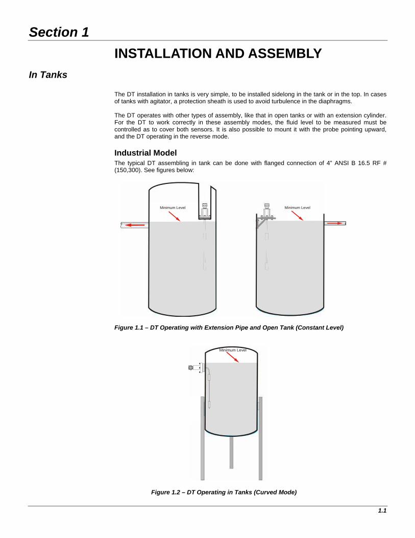
The DT installation in tanks is very simple, to be installed sidelong in the tank or in the top. In cases of tanks with agitator, a protection sheath is used to avoid turbulence in the diaphragms. The DT operates with other types of assembly, like that in open tanks or with an extension cylinder. For the DT to work correctly in these assembly modes, the fluid level to be measured must be controlled as to cover both sensors. It is also possible to mount it with the probe pointing upward, and the DT operating in the reverse mode.
Industrial Model The typical DT assembling in tank can be done with flanged connection of 4” ANSI B 16.5 RF # (150,300). See figures below:
Minimum Level Minimum Level
Figure 1.1 – DT Operating with Extension Pipe and Open Tank (Constant Level)
Minimum Level
Figure 1.2 – DT Operating in Tanks (Curved Mode)

DT300 – Installation Guide
1.2
Minimum Level
Minimum Level
Figure 1.3 – DT Operating in Tanks (Reverse Mode) For processes with severe agitation, a standpipe can be constructed on the side of the tank. See details in the Figures below.
Figure 1.4 – DT in a Standpipe
The assembly in a standpipe is frequently used for measuring interface level, as shown in the subsequent examples. See the figures below:

Installation and Assembly
1.3
Figure 1.5 – Interface Level with a Standpipe and Communicating Vessel
The interface level can also be measured directly in tanks. See Figure 1.6.
Oil
Water
Figure 1.6 – Interface Level in the Tank
NOTE Interface level measuring should respect a maximum 500mm variation that is the center-to-center distance of the sensor diaphragms.
Sanitary Model The sanitary DT installation can be made directly in the tank. For sanitary installations, the Smar developed a tank adapter, which can be installed in new or existing tanks, avoiding the use of welding, without need to polish the tank again.
Below are shown illustrative Figures of the tank adapter for sanitary DT installation:

DT300 – Installation Guide
1.4
Figure 1.7 – Tank Adapter Assembly
Figure 1.8 – Example of Tank Adapter Assembly Figure 1.9 – Example of Tank Adapter Assembly (Tank External Side View) (Tank Internal Side View)
Tank wall
External side of the tank
Internal sideof the tank
Tri-clamp 4”
Squeeze screw

Installation and Assembly
1.5
In Line With Sampling Tanks For in-line measuring, the DT must be installed so that all or portion of the process fluid circulates on it. For that, Smar developed sampling tanks, with only one by-pass and a little load loss in the main line, so as to guarantee the sample circulation in the DT. There are clean and dirty fluid vessel and/or with solids in suspension. See the Figures below.
Tanks of Divided Flow This installation standard must be used when there are big variations of pressure and flow.
Connectionto process:Flange Ø 2”
Ø 6”
Figure 1.10 – Typical Installation for Clean Fluids Figure 1.11 – Typical Installation for Dirty Fluids and/or Solids in Suspension (For flow up to 2 m3/H) (For flow up to 8 m3/H)
Tanks of Ascending Flow
Figure 1.12 – Typical Installation for Ascending Flow Figure 1.13 – Typical Installation for Ascending Flow (For flow up to 20 m3/H) (For flow up to 80 m3/H)
INDUSTRIAL MODEL
Connection to process:Ø 8” X 150#
Ø 12”
Connection to process:Ø 2 ½” - Tri-Clamp
Ø 6”
SANITARY MODEL
Connectionto process:Flange Ø 1”
Ø 4”

DT300 – Installation Guide
1.6
Figure 1.14 – Typical Installation for Ascending Flow Figure 1.15 – Typical Installation for Ascending Flow (For flow up to 40 m3/H) (For flow up to 20 m3/H)
Tanks of Communicant Vessel
Figure 1.16 – Typical Installation with Stand Pipe (for interface level)
Connection to process:Ø 2”
Ø 8”
INDUSTRIAL MODEL
Ø 6”
Connection to process:Ø 2”
INDUSTRIAL MODEL
Connection to process:Ø 2”
INDUSTRIAL MODEL

Installation and Assembly
1.7
Typical Installations Schemes
Figure 1.17 – By-pass, with a Valve in the Main Line, to Force the Circulation in the By-pass
Figure 1.18 – By-pass with the Fluid Flowing to a Tank
OPENING IN TANK
DT300 – Installation Guide
1.8
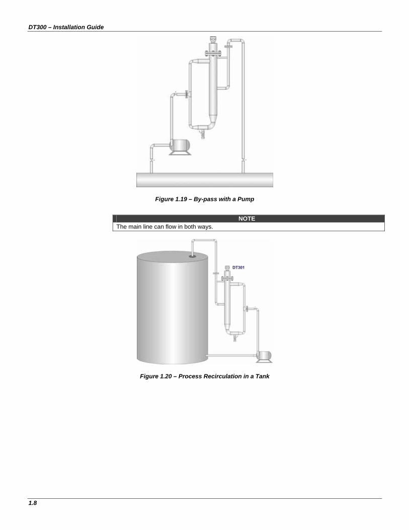
Figure 1.19 – By-pass with a Pump
NOTE
The main line can flow in both ways.
Figure 1.20 – Process Recirculation in a Tank

Installation and Assembly
1.9
Figure 1.21 – By-pass with Pitot Tube
Figure 1.22 – Installation with all Fluid Flowing in a Ascending Flow Vessel

DT300 – Installation Guide
1.10

Section 2
2.1
APPLICATION
Sugar and Alcohol
This section includes practically all sugar and alcohol applications; from process description to a few installation tips that should be observed. Mud Density in Clarifiers In this application, the density measurement of the mud is made in line, after the continuous displacement pump. Note that in the construction of the sampling vessel, the mud line diameter increases, while the fluid speed decreases when going through the sensors, due to presence of sand, bagasse residue and other solids in suspension. The lower part of the output should always guarantee that the upper DT repeater be completely immersed. The complete and immediate cleansing of the system is recommended when the clarifier stops working, thus avoiding that the mud dries on the sensors.
Figure 2.1 – Ascending Flow Installation
Considerations 1 - This configuration refers to density measurement, and not brix, because it is not a totally sugary solution. Therefore, the engineering unit in question is density, Kg/m³ for example. 2 - When compared the instrument measurement with laboratory analysis must be care because the density varies with the temperature. 3 - Using the experience of the operators, the ideal density for the mud is found. This density value is adopted as set-point in the controller. 4 - The controller will act in the frequency varying of the mud pump to keep the desired density for the mud. Milk of Lime Dilution In many cases the lime dilution that is added to the juice is controlled by laboratory analysis. The DT can also do this control online.

DT300 – Installation Guide
2.2
Figure 2.2 - DT measuring the concentration (Baumé degree) of the milk of lime
NOTE
If the process stops, the sampling tank must be drained and the diaphragms cleaned with water.
Figure 2.3 – Process without lime incrustation in the DT diaphragms

Application
2.3
Evaporation The DT also can be used to measure the efficiency of the evaporators, since is directly output Brix function versus input Brix.
Measuring the Brix of the Pre Evaporated Juice In this application, the use of the separator tank is recommended to create the “flash” effect. The “flash” effect will help producing air bubbles and eliminate the foam before entering the sampling vessel. See the installation with “separator tank”.
SeparatorTank
Hot water for cleaning
Drain
Figure 2.4 – Installation Scheme of pre-evaporated juice
Syrup Brix Measuring between Effects and at Final Effect of Evaporation In this application, the sample must be collected after the syrup pressure pump, sending the sample back to the syrup tank. Also in this case, the use of the separator tank will release the air bubbles and eliminate the foam.
SeparatorTank
Hot water for cleaning
Drain
Figure 2.5 – Syrup Brix Installation Scheme

DT300 – Installation Guide
2.4
Molasses Brix Measuring (poor, rich and final) The recommended procedure is to install the sampling vessel with the ascending flow below the diluting tank, and by gravity the sample will circulate back to the tank of diluted molasses. A line of hot water for eventual cleanings is also recommended.
SeparatorTank
Hot water for cleaning
Drain
Figure 2.6 – Installation for Molasses Brix Measurement

Application
2.5
Fermentation
Fermented Must Brix Measuring Note that the side model is installed directly in the fermentation tank, and that the height should consider that the sensors should be always submerged.
FERMENT
Sample
Max
imum
leve
l of t
he fe
rmen
t
1000
mm
Figure 2.7 - DT in Fermentation Tank It is recommended to install the DT in such way that the inferior sensor is above of the ferment maximum level and also to install a sample point near the DT. Must Brix Measuring (Dilution) To dilute must (water, molasses and juice), the DT should always be installed after the static mixing set. If foam and air bubbles arise, the use of the separator tank is recommended, as well as the ascending flow sampling vessel with an overflow output. To avoid eventual infection risks, a hot water line is recommended during stops, for the correct cleaning and asepsis of the measurement system.
SeparatorTank
Hot water for cleaning
Drain
Figure 2.8 – Must Brix Installation Scheme
DT300 – Installation Guide
2.6
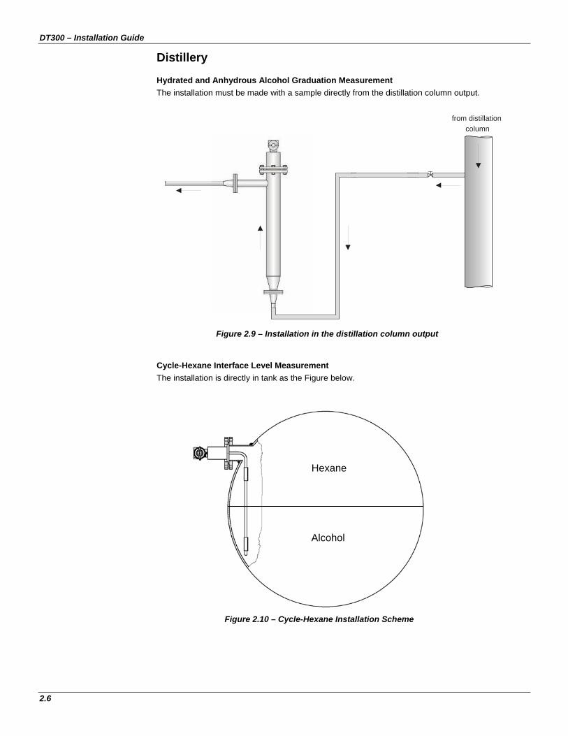
Distillery Hydrated and Anhydrous Alcohol Graduation Measurement The installation must be made with a sample directly from the distillation column output.
Figure 2.9 – Installation in the distillation column output
Cycle-Hexane Interface Level Measurement The installation is directly in tank as the Figure below.
Figure 2.10 – Cycle-Hexane Installation Scheme
from distillationcolumn
Hexane
Alcohol

Application
2.7
Sugar Refinery Sugar Dilution A sample of diluted sugar is collected from the tank and recirculates to the same tank.
Figure 2.11 – Divided Flow Tank installed after the process pump
DilutedSugar

DT300 – Installation Guide
2.8
Mining
Some applications in mining are: mill output, hidrocyclones, pulp dilution, flotation, thickener, removal of mud, concentration of acids, milk of lime, pulp of ore, gravimetric classifiers, etc.
Mill Output In this application the ore has big granulometry and it is used a depressurized tank with automatic drain for measuring the density.
The excavated ore, before processing, passing by the mill and is diluted in water for treatment by other chemical products. Being too abrasive, the ore pulp should be immersed in a rubber-coated tank to reduce this abrasion of the sampling tank.
Figure 2.12 – Mill Output
Pulp of Ore
The density of ore diluted in water can be measured in a by-pass with a rubber-coated tank using a pressurized sampling tank.
The drain valve should be partially opened to avoid blockage in the bottom of the tank.
Figure 2.13 – Mining Installation Example
NOTE The drain valve should be kept partially open.

Application
2.9
Mining Loop Test
Figure 2.14 – Mining Loop Test Installation Installation in Tank It is possible to install the DT in the tank using a standpipe for measurement. This kind of installation is used even if there is agitator in the tank.
Figure 2.15 – Installation in Tank with Standpipe

DT300 – Installation Guide
2.10
Thickener Output For measuring density in the thickener output a sample line is taken after the pump and a rubber-coated sampling tank of ascending flow is used.
COME FROMTHICKENER
Figure 2.16 – Thickener Output
Milk of Lime For this application an ascending flow sampling tank is used.
Figure 2.17 – Lime Milk

Application
2.11
Acid Concentrations Some mining have acid plants. The DT is used for measuring acid concentration in these plants. Usually this installation is made in a by-pass of the main line.
Figure 2.18 – Bypass Installation
Chemical Industry
In this industrial segment, the DT is used for measuring concentration of acids, salts, caustic soda, etc. When using the DT on these applications, it is possible to use a polynomial to get the desired unit. For example: % of sulfuric acid.
Density / Concentration of Salt The DT is applied to control the salt water concentration, before the electrolysis occurs The DT is installed in line, as shown on Figure 2.19 below.
DT301
Figure 2.19 – Recirculation of the solution with Pump

DT300 – Installation Guide
2.12
NOTE For corrosive saline fluids, the sampling tank should be fiber made.
It is possible that the DT measures the concentration in grams per liter, although your software may not have this unit. To this effect, a density and temperature field survey should be carried out by the DT and the concentration measured by laboratory analysis. With this survey, a polynomial is developed for DT configuration. Caustic Soda Concentration Caustic soda is obtained through the electrolysis of treated salt water (sodium chloride solution and water). When using the diaphragm cell process, the liquid caustic soda - commercial degree is obtained; if the mercury cell process is used, the Rayon-degree liquid caustic soda is obtained. Both have an aqueous, limpid solution form, containing about 50% of sodium hydroxide (NaOH) in weight. The % NaOH can be measured online using an installation as showed below.
Figure 2.20 – Pump Recirculation
Acids Density For measuring density or concentration of acid, usually the material of the probe of the DT is Hastelloy and the sampling tank is in fiber glass.
Figure 2.21 – Installation measuring Chlorohydric Acid

Application
2.13
Petrochemical Industry Tank of Oil Treatment The DT is usually installed in standpipe as shown on Figure 2.22.
OIL
WATER
Figure 2.22 – DT Installation Scheme with Standpipe
As in this application there is NaCl, the DT probe is Inox made, although the diaphragms used are hastelloy. For DT configuration, it is installed in the communicating vessel and the densities of both composites are verified. The density values are noted down and the range is programmed, being 0% is the smallest density value, and 100% is the highest density value. Concluded this procedure, the display is configured to show "PV%". Example For sea water and oil: The sea water level in the tank is increased, and a density of 1.125 g/cm3 is measured. After writing the water density value, the tank is drained, so that the communicating vessel is filled with oil, and the value measured by the DT is 0.8 g/cm3. Configure the 4mA = 0.8 g/cm3 and 20mA = 1.125 g/cm3 and the display will show the PV percent.
Figure 2.23 – Salt water/oil Interface Level Measuring

DT300 – Installation Guide
2.14
Petroleum Derivative Products In the quality control of transported fuels, the DT is used for in-line measuring of the gasoline density, kerosene, lubricant, oil, diesel oil, GLP and alcohol. The sampling vessel fluid is collected by a Pitot tube, inside the main pipe. See the installation scheme on Figure 2.24. The identification of oil by-products petroleum derivative (gasoline, kerosene, diesel oil and GLP, besides ethanol) is done by density in pipes.
Figure 2.24 - Reception of process fluid by a Pitot Tube
Figure 2.25 – Density measurement to identify the product

Application
2.15
Another way of installing the DT in this application is collecting the fluid through a pump. This procedure allows that the flow in the line goes in both directions.
Figure 2.26 – Pump Recirculation
Figure 2.27 - Pump Recirculation

DT300 – Installation Guide
2.16
Crude Oil Density Crude oil density is measured in fiscal measuring stations, in order to obtain the mass flow value.
Figure 2.28 - Fiscal Measuring Skid PLG Density The PLG density measuring can be done directly in tanks. See Figure 2.29.
Figure 2.29 – PLG Measuring in Tank

Application
2.17
Beverage Industry Plato Degree Measuring in Breweries The DT applications are in must boiling and fermentation tank. The DT is installed directly in the tank, with the tank adapter. The sanitary DT is installed as described previously.
Figure 2.30 – Plato Degree Measurement in Fermentation Tank
Tank Volume Measuring The DT is used also in density measuring to correct the tank volume. Brix Degree measuring in the Soft-drink Industry
Figure 2.31 - DT Measuring Brix in the Soft-drink production

DT300 – Installation Guide
2.18
The soft-drinks applications measure the Brix of sweet water, syrup and the finished beverage. The sampling vessel receives a sample from a pump that collects the liquid from the main line and returns it at a subsequent point, on the same line.
Figure 2.32 – Installation Scheme
Figure 2.33 - DT measuring Sweet Water Brix

Application
2.19
Pulp and Paper Measuring Weak Black Liqueur Concentration (before evaporation) and Strong Black Liqueur (after evaporation) The density transmitter is installed in line with the use of a sampling vessel that can be for ascending flow or divided inlet. The Figures 2.34 and 2.35 show examples of installations for black liqueur concentration measuring.
Figure 2.34 – Example 1 Figure 2.35 – Example 2
For black or green liqueur applications, some precautions against incrustation are necessary. Hot water circulating is indispensable on the sampling vessel, and a periodic cleanup is necessary.
Figure 2.36 – Black Liqueur Measuring (ascending flow) Some users prefer to work with ºBaumé as measuring unit, while others prefer to use Percentage of Solids.

DT300 – Installation Guide
2.20
Green Liqueur Density Measuring Due to green liqueur being extremely subject to incrustations, the installation in this case should not use small diameter pipes because they can easily clog. The best installation for this application is to use an ascending flow sampling vessel that for not having small diameter tubes provides easy density transmitter cleaning, when the process stops. A hot water inlet for periodic cleaning is also necessary. Usually the green liqueur storing tank has a recirculation system that can be used to install the sampling vessel. The following figures illustrate this type of installation.
Figure 2.37 –Green Liqueur Installation Figure 2.38 – Overflow Details
Other applications are: caustic soda concentration, milk of lime and methanol density (similar to the sugar and alcohol distilling process), etc. Milk of Lime
Figure 2.39 – Milk of Lime Installation

Application
2.21
Caustic Soda Concentration
Figure 2.40 – Caustic Soda Concentration Measurement Installation
Food Industry
Miscela Concentration in Vegetable Oils In the process of soybean oil extraction have the miscela, a mixture of oil and hexane. The process of separation of these two components is called miscela distillation. The control of the miscela removal is made through the density or concentration. For this calculation are necessary the density and temperature data, besides a software for a polynomial survey. When this polynomial is generated, the DT makes this calculation, by supplying a signal that corresponds to the concentration of miscela. The DT installation for the miscela is shown on Figure 2.41.
Figure 2.41 – Pump Recirculation
DT301

DT300 – Installation Guide
2.22
Pre-condensed Milk Density The milk density is measured after the evaporator. The DT installation is done as shown the Figure 2.42.
Figure 2.42 – Measuring pre-condensed Milk Density
Soluble Coffee The DT can be used in the concentration process of soluble coffee, when the efficiency of the evaporators is measured. The installation is made using an ascending flow sanitary tank as showed on the Figure below.
Figure 2.43 - DT measuring concentration of soluble coffee extract

Application
2.23
Brix of Orange Juice after Filtering Direct installation in tank.
Figure 2.44 – Installation for orange juice °Brix measuring

DT300 – Installation Guide
2.24