dense vertical su-8 microneedles drawn from a heated … microneedle tips in the drawing process....
TRANSCRIPT

This content has been downloaded from IOPscience. Please scroll down to see the full text.
Download details:
IP Address: 137.132.123.69
This content was downloaded on 23/01/2015 at 10:11
Please note that terms and conditions apply.
Dense vertical SU-8 microneedles drawn from a heated mold with precisely controlled volume
View the table of contents for this issue, or go to the journal homepage for more
2015 J. Micromech. Microeng. 25 025013
(http://iopscience.iop.org/0960-1317/25/2/025013)
Home Search Collections Journals About Contact us My IOPscience
1 © 2015 IOP Publishing Ltd Printed in the UK
1. Introduction
Currently, drug delivery systems are focusing on how to transport proteins, DNA, genes, antibodies and vaccines effi-ciently and safely into the human body. However, conventional drug delivery approaches, such as oral administration and
hypodermic injection, have their limitations. For example, oral delivery may inactivate a drug through phase I metabolism [1] while hypodermic injection requires trained personnel [2]. To overcome these drawbacks, transdermal drug delivery has been attracting tremendous attention as a safe, easily acces-sible and patient-friendly approach [3–5]. Most biomolecules,
Journal of Micromechanics and Microengineering
Dense vertical SU-8 microneedles drawn from a heated mold with precisely controlled volume
Zhuolin Xiang1,2,3, Hao Wang1, Suresh Kanna Murugappan3, Shih-Cheng Yen1,3, Giorgia Pastorin2 and Chengkuo Lee1,3
1 Department of Electrical and Computer Engineering, National University of Singapore, 4 Engineering Drive 3, Singapore 117576, Singapore 2 Department of Pharmacy, National University of Singapore, 3 Science Drive 24, Singapore 117543, Singapore 3 Singapore Institute for Neurotechnology (SiNAPSE), National University of Singapore, 28 Medical Drive, #05-COR, Singapore 117456
E-mail: [email protected] and [email protected]
Received 23 August 2014, revised 25 November 2014Accepted for publication 26 November 2014Published 22 January 2015
Abstract Drawing lithography technology has recently become a popular technique to fabricate (3D) microneedles. The conventional drawing process shows some limitations in fabricating dense, scale-up and small microneedles. In this study, we demonstrate a new drawing lithography process from a self-loading mold which is able to overcome these challenges. Different from the conventional molds which have difficult alignment and loading issues, a released SU-8 membrane is attached onto a SU-8 coated wafer to generate an innovative self-loading mold. The physically distinct SU-8 colloid in this mold successfully avoids the merging of the microneedle tips in the drawing process. Meanwhile, the same SU-8 colloid in mold can provide microneedles with uniform lengths on a large surface area. Furthermore, a low temperature drawing process with this improved technique prevents sharp tips from bending during the solidification stage. Remarkably, this new drawing lithography technology can fabricate microneedles with various lengths and they are strong enough to penetrate the outermost skin layer, namely the stratum corneum. The spacing between two adjacent microneedles is optimized to maximize the penetration rate through the skin. Histology images and drug diffusion testing demonstrate that microchannels are successfully created and the drugs can permeate the tissue under the skin. The fabricated microneedles are demonstrated to deliver insulin in vivo and lower blood glucose levels, suggesting future possible applications for minimally invasive transdermal delivery of macromolecules.
Keywords: microneedles, transdermal drug delivery, drawing lithography, SU-8, insulin delivery
(Some figures may appear in colour only in the online journal)
Z Xiang et al
Printed in the UK
025013
jmm
© 2015 IOP Publishing Ltd
2015
25
j. micromech. microeng.
jmm
0960-1317
10.1088/0960-1317/25/2/025013
Papers
2
journal of micromechanics and microengineering
AT
0960-1317/15/025013+10$33.00
doi:10.1088/0960-1317/25/2/025013J. Micromech. Microeng. 25 (2015) 025013 (10pp)
Z Xiang et al
2
however, cannot pass through the skin barrier due to their unfavorable hydrophilicity and macro size (over 500 Da) [6, 7]. Thus, microneedles have been introduced to create microchannels on the skin surface by penetrating the outermost layer, i.e. the stratum corneum. These so-formed transitory pores allow local permeation of drugs into the skin [8–11].
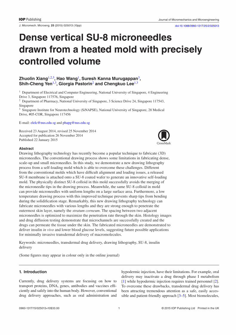
In recent years, micro-electromechanical systems (MEMS) technology has enabled microneedles to be fabri-cated by different materials, including silicon [12], stainless steel [13], titanium [14], tantalum [15] and nickel [16]. Although these materials can be easily used to fabricate sharp microneedles and provide sufficient mechanical stiffness for penetration purposes, devices made of these materials are prone to damage [17] and may not be biocompatible [18]. As a result, polymer-based microneedles, such as SU-8 [19, 20], polymethylmeth-acrylate (PMMA) [21, 22], polycarbonates (PC) [23, 24], maltose [25, 26] and polylactic acid (PLA) [27, 28], have attracted more and more attention lately. In partic-ular, SU-8 has been investigated intensively in recent years to fabricate microneedles due to its biocompatibility, which can be achieved after certain pretreatments (hard baking, isopropanol treatment, oxygen plasma treatments) [29–31] and its simplicity to be patterned as a structural material. Even though conventional fabrication technologies for microneedles, such as stainless steel molding technology [32], inclined Ultraviolet (UV) exposure technology [33], polydimethylsiloxane (PDMS) molding technology [34, 35], reactive ion etching technology [36] and etched lens backside exposure technology [37] can be adopted to obtain devices with ultra-sharp geometry from polymer materials, they are time-consuming and expensive. To avoid these limita-tions, Lee et al reported a drawing lithography technology, which leveraged on the different viscosity of polymers under different temperatures, to easily pattern 3D polymer microneedles [38–41]. Nevertheless, it was demonstrated that the spacing between two nearby microneedles was critical for the successful formation of individual microneedles [42, 43]: a distance between two neighboring microneedles smaller than 900 µm was shown to be detrimental for the formation of individual needles. It was also found that, when the density of the microneedles kept increasing, parts of the micronee-dles formed clusters rather than sharp tips (figure 1(a)). This represented the main hurdle for this drawing lithography tech-nology and hampered the fabrication of dense microneedles. Moreover, from the mathematical model reported previously [44], the length of the microneedles was mainly determined by the extensional strain rate in the polymers. In the conventional drawing lithography process, the length of microneedles was controlled by adjusting the temperature, which affected the extensional strain rate. However, the temperature distribution and the rate of change in the temperature were not necessarily uniform over the baked polymers. Hence, the lengths of fab-ricated microneedles may vary remarkably across the same sample, especially when this sample has a large area. Thus, the temperature control mechanism had a constraint for the scale-up of the microneedles in drawing lithography tech-nology. Furthermore, the previous process needed a relatively high temperature for low polymer viscosity to obtain smaller
microneedles. However, there was a high chance that this high temperature led microneedle tips to bend in the final solidifi-cation process (figure 1 (b)), which impeded the successful fabrication of small microneedles by drawing lithography technology.
Taking all of these limitations into consideration, we demonstrated a new drawing lithography process from a self-loading mold, which is able to overcome these challenges. A released SU-8 membrane was attached onto a SU-8 coated wafer to generate an innovative self-loading mold. Physically separated SU-8 colloid in this mold successfully avoids any merging of the microneedle tips in the drawing process. Meanwhile, the same SU-8 colloid in the mold can provide microneedles with uniform lengths on a large surface area. The low temperature drawing process in this improved technique prevents sharp tips from bending during the solidification stage. Remarkably, this new drawing lithography technology can fabricate microneedles with various lengths and which are strong enough to penetrate the stratum corneum. In vitro and in vivo tests prove the successful penetration of fabricated microneedles and its feasibility to deliver macromolecules such as insulin.
2. Design and fabrication
The fabrication process is shown in figure 2. It can be divided into three parts: self-loading SU-8 mold fabrication, SU-8 pillar fabrication and SU-8 tip fabrication.
A self-loading SU-8 mold, from which the micronee-dles were drawn, was designed to physically separate SU-8 source and control the source volume. In conventionally pat-terned mold, the source material needs to be loaded inside the
Figure 1. Problems with microneedles with conventional drawing lithography technology. (a) Nearby microneedles merge and form clusters rather than sharp tips; (b) High temperature in the conventional fabrication process leads microneedle tips to bend in the solidification process.
J. Micromech. Microeng. 25 (2015) 025013

Z Xiang et al
3
mold [45]. It requires a fine alignment and the loading volume is hard to control precisely. Therefore, we applied a released SU-8 membrane on top of a wafer coated with SU-8 to imple-ment a self-loading SU-8 mold.
The fabrication of the self-loading SU-8 mold started from a layer of polyethylene terephthalate (PET, 3M USA) film pasted onto a Si substrate by sticking the edge area with kapton tape (figure 2 (1a)). After spin coating, soft baking, UV exposure and development, a 350 µm thick SU-8 mem-brane was patterned on the PET substrate (figure 2 (1b)). Due to poor adhesion between the PET film and the cross-linked SU-8 layer, the SU-8 membrane could be easily released from the PET substrate by removing the kapton tape and slightly bending the PET film (figure 2 (1c)). A layer of 250 µm thick SU-8 was spin coated onto another piece of wafer. This wafer was soft baked to minimize the SU-8 fluidity. The SU-8 mem-brane was then attached onto the baked SU-8 wafer (figure 2 (1e)). By applying a slight depression with tweezers, the SU-8 membrane was stuck onto the substrate and the SU-8 colloid filled in the holes (figure 2(1f)). Since the highly viscous SU-8 2100 was chosen as the source, the SU-8 colloid could be con-trolled precisely to fill into the holes on the membrane without any spillage. In this way, a self-loading SU-8 mold filled with SU-8 source was prepared without any tedious loading process.
An array of 350 µm high SU-8 pillars was fabricated on a glass substrate as a frame to draw the SU-8 colloid. A uniform
spin coating is critical to the patterning of SU-8 pillars with the same height. In order to avoid the common edge effect in the thick photoresist patterning process [46], the SU-8 deposition was conducted in two steps. In each step, SU-8 2100 was spun at 2000 rpm for 30 s, followed by prebaking steps at 65 °C for 10 min and 95 °C for 120 min. After the prebaking steps, this SU-8 layer was exposed to 650 mJ cm−2 ultraviolet energy and developed to define the structure of the pillars (figure 2 (2b)).
The fabrication of the SU-8 tips was divided into four steps. First, the SU-8 pillar sample was flipped over and attached to a precision stage, which could control the sample position in three-dimension. The self-loading SU-8 mold was fixed on a 95 ºC hotplate surface (figure 2 (3a)). Secondly, since the SU-8 pillars were fabricated on a transparent glass substrate, it was easy to align the pillars with the self-loading SU-8 mold by backside observation. The device of the SU-8 pillars was immersed in the mold and the SU-8 colloid was coated on the surface of the pillars (figure 2 (3b)). Thirdly, the SU-8 pillars were drawn away from the SU-8 colloid. Since the tempera-ture in the air was lower than the temperature in the SU-8 colloid, the coated SU-8 quickly solidified. Due to the limited SU-8 source in the self-loading mold, the connection between the SU-8 pillars and the SU-8 colloid gradually became a SU-8 bridge during the drawing process (figure 2 (3c)). At last, when the drawing speed was increased, the connection shrank and then broke. The end of the shrunken SU-8 bridges
Figure 2. Fabrication process for dense microneedles.
J. Micromech. Microeng. 25 (2015) 025013

Z Xiang et al
4
formed sharp conical tips at the top of the SU-8 pillars (figure 2 (3d)). The SU-8 microneedle device was then UV exposed, post baked, hard baked and treated with oxygen plasma. This postprocessing step not only induced a crosslink in the SU-8 to enhance the stiffness of the device, but also increased its biocompatibility [30]. Different from the drawing lithography technology that we reported before [43, 47], the baking tem-perature in this drawing process was not changed. Therefore, it avoided any bending of the tips, which is normally induced by high temperature.
In the whole process, all the SU-8 colloid was confined in a self-loading mold and physically separated from each other. It prevented the SU-8 microneedles from merging even when the nearby micropillars were close to each other. Meanwhile, the same SU-8 source volume controlled by the patterned SU-8 membrane led to uniform lengths for the fabricated micronee-dles. Finally, the low-temperature process in the SU-8 mold avoided the formation of bent tips at the end of the microneedles.
3. Results and discussion
3.1. Length dependency of microneedles
In conventional processes, the length of microneedles is controlled by the baking temperature. Polymer viscosity decreases as the baking temperature increases, which leads to a lower extensional strain rate in the polymer. To a certain extent, polymer gravity force dominates extension force and the drawn polymer end shrinks into sharp tips [47]. However, we noticed that when the size of the microneedles is reduced, the increased temperature resulted in bent tips. Therefore, the SU-8 mold that we used in this new drawing process was aimed at solving this problem. Since the height of the mold was the same as the thickness of the SU-8 membrane, the volume of the mold was only determined by the diameter
of the holes on the membrane. Thus, the SU-8 colloid source inside the mold could be controlled by changing the diameter of the holes. If the volume of the SU-8 colloid source was lim-ited, when most of the SU-8 colloid was drawn away by the SU-8 pillars and solidified, the SU-8 colloid left in the mold would not be sufficient to form a cylindrical shape. Indeed, since the SU-8 colloid in the mold became less and less, the drawn SU-8 microneedles gradually formed a conical shape and ended with a sharp tip.
Figure 3 shows the microneedles with different lengths fabricated by changing the diameter of the holes rather than by increasing the temperature. In order to study the relation-ship between the diameter of the holes on the membrane and the corresponding length of the drawn microneedles, mem-branes with different holes were used as molds to fabricate the microneedles. The varying diameters ranged from 240 to 510 µm with 30 µm intervals. Ten samples were fabricated to calculate the errors in each diameter. The results are shown in figure 4. From the measurement, it was confirmed that the microneedles fabricated according to this method are uniform and repeatable. Their lengths can be controlled by the diam-eter of the holes on the membrane.
3.2. Stiffness testing for microneedles
The microneedles were mainly used to create microchannels on the skin surface. In order to prove that the microneedles had sufficient stiffness for successful penetration, their buck-ling force was tested. Microneedles with varying lengths from 400 to 1000 µm were loaded under an axial compression with Instron Microtester 5848 (Instron, USA). Ten microneedles with the same length were tested in each group. The equip-ment drove a microneedle against a metal plate at a speed of 20 µm s−1 until the microneedle broke. Davis et al [48] had studied the failure point of microneedles and defined
Figure 3. Optical images for microneedles with different lengths. (Scale bar: 500 µm).
J. Micromech. Microeng. 25 (2015) 025013

Z Xiang et al
5
that the sharp discontinuity point marked the fracture of the microneedle, which was also adopted by Mansoor et al [16] and Geyssens et al [49]. We followed the same method in the measurement of our microneedles. The failure loading point could be observed when the loading sensor output had a sharp change. The force and its corresponding displacement data were recorded by a computer.
Figure 5(a) demonstrates one representative example of buckling force testing for a 500 µm high microneedle. The axial force applied to the microneedle increased with the plate displacement until the maximum load was reached. The frac-ture threshold was indicated by a discontinuity in the detected force and confirmed by visual observation during the test. After this fracture point, the loading plate continued to press against the crushed microneedle under less force. Figure 5(b) showed the microneedles’ buckling force changed with their lengths. From Euler’s equation, π=F EI KL/ ( ) ,2 2 the buck-ling force is proportional to the area moment of inertia, I. The cross section of the microneedle is approximately a circle. Thus, its area moment of inertia has an exponential growth with the microneedle radius. For our devices, the length and cross section area of the microneedles were determined by the SU-8 source in the mold. Those microneedles whose lengths were less than 500 µm did not have sufficient SU-8 source to form a perfect conical geometry (figures 3(a) and (b)). The base area of these microneedles shrunk sharply, resulting in a relatively small bucking force in this range. Longer micronee-dles took more SU-8 source from the cavities in the mold, which resulted in a decreased curvature in their bottom part and a larger cross section area. Thus, the corresponding buck-ling force increased. However, when the microneedles’ length was larger than 800 µm, their base area was similar to the fixed cross section area of micropillars, which were used as frames in the drawing lithography process. Their corresponding buckling force therefore tended to be constant.
3.3. Optimization of microneedle spacing
In theory, denser microneedles would contribute to the for-mation of more microchannels on the skin surface, which
would enhance the transdermal delivery of bioactive mole-cules. However, as addressed in the introduction, the previous drawing lithography technology was confronted with a density limitation: when the spacing between two nearby micronee-dles was reduced to less than 900 µm, their tips merged into clusters rather than forming individual microneedles [43].
Therefore, in this study, a self-loading SU-8 mold was leveraged to solve this problem. As described in the fabrica-tion process, the SU-8 mold was a SU-8 membrane attached onto the SU-8 colloid surface (figure 6(b)). The SU-8 colloid source was physically separated by the SU-8 mold and their spacing was determined by the distance D on the membrane (figure 6(a)). Since the nearby SU-8 colloid source had no overlap between each other, the spacing of the microneedles could shrink to a narrow gap. However, Yan et al reported that a ‘nail bed’ effect may occur when the density of the microneedles is increased [50]. When an excess number of microneedles was applied to a small skin sample, the force distributed among the microneedles was not sufficient for a single microneedle to penetrate the skin surface. Therefore, although the self-loading SU-8 mold could offer an approach to fabricate a denser microneedle chip, its density needed to be optimized to guarantee skin penetration efficiency.
Figure 4. The relationship between microneedle lengths with the diameters of the holes on the SU-8 membrane.
Figure 5. (a) A representative example of the buckling force test result for a 500 µm high microneedle. (b) The relationship between the microneedle buckling force and their lengths.
J. Micromech. Microeng. 25 (2015) 025013

Z Xiang et al
6
A batch of 10 × 10 microneedle arrays which had the same length but different spacing was fabricated to study the opti-mized spacing. Their spacing changed from 200 to 500 µm with 50 µm intervals. After these microneedles were applied to a rats’ skin surface with the same force, 50 µL of methylene
blue was used to stain the skin samples. The stain was left on the sample for 10 min and then the excess stain was removed by ethanol wipes. Since the methylene blue only diffused into the penetrated holes, the penetration rate was visually evaluated through the recorded images. Figure 7 shows the representa-tive results. When the spacing increased, it was obvious that more microneedles successfully penetrated the skin surface.
Figure 6. (a) Optical image for the SU-8 mold. (Scale bar: 500 µm) (b) Illustration for the SU-8 mold.
Figure 7. Different penetration rates on the representative skin samples which were treated by microneedles with different spacings (a) 250 µm (b)300 µm (c)350 µm (d) 400 µm. (Scale bar: 500 µm) The greater the number of blue spots on the skin sample, the higher the penetration rate of the corresponding microneedle chip.
Figure 8. The relationship between the successful penetration rate and the spacing between two nearby microneedles.
Figure 9. Histology image of the penetration of two microneedles (Scale bar is 200 µm).
J. Micromech. Microeng. 25 (2015) 025013

Z Xiang et al
7
From the 70 testing samples (10 samples for each spacing), we summarized their penetration rate (figure 8). If the spacing between two nearby microneedles was larger than 400 µm, more than 95% of the microneedles could successfully create microchannels on the skin samples. Most microneedles on the samples with smaller spacing, however, failed to penetrate the skin. Therefore, 400 µm spacing was chosen as the optimal value to fabricate our final devices.
3.4. Histological examination
Histological images were taken to show the details of the micro-channels created by the fabricated microneedles. Skin samples after penetration were washed in 1X phosphate buffered saline (PBS) (Vivantis Inc US) and fixed in 4% paraformaldehyde (Electron Microscopy Sciences, USA) for 48 h at 4 °C. Then cryoprotection with 30% Sucrose (Fischer Scientific, UK) was applied to the samples for 24 h at 4 °C and embedded with an optimal cutting temperature (OCT) medium. Cryosections of 20 µm were sliced and dried at room temperature for 24 h, stained with hematoxylin and eosin (H and E) to locate the microneedle penetration in the skin. The result is shown in figure 9. The penetration successfully induced conical micro-channels on the skin epidermis for delivery purposes.
3.5. Drug diffusion testing in vitro
The data presented so far have shown microneedle penetra-tion, but not addressed the drug diffusion process. After the rat skin was pretreated with the fabricated microneedles,
the device induced microchannels on the skin surface. The drug diffused to the tissue through these microchannels. In order to present this scenario, 200 µL of physiological saline solution containing fluorescent Sulforhodamine (Sigma-Aldrich, Singapore) was applied to the rat skin sample after it was pretreated with the fabricated microneedles. Then the skin sample was investigated by a confocal microscope. The permeation pattern of the florescent solution along the micro-channels showed the solution diffusion results. Figure 10 indicates the diffused area from a depth of 20 to 180 µm below the skin surface. The black area was a control area without any diffused florescence. In contrast, the illuminated tissues indi-cated the area where the solution diffused through. Since the microchannels were created by the conical microneedles, the diameter of the microchannel decreased when the penetrated depth increased. Most of the Sulforhodamine solution was confined to the microchannels and only some of it diffused to the nearby tissue. Thus, the diffusion area also decreased in the deeper region.
3.6. Transdermal delivery of insulin in vivo
Transdermal delivery of insulin was tested in vivo to prove the function of fabricated microneedles in practical experi-ments. All the procedures were performed under protocol and approved by the Institutional Animal Care and Use Committee at the National University of Singapore.
200 ~ 250 g Sprague–Dawley rats were injected with 50 mg kg−1 streptozotocine (Sigma-Aldrich, Singapore) in cit-rate buffer (pH 4.2) by intraperitoneal injection to generate a
Figure 10. Images of confocal microscopy of the site where one microneedle inserted shows that the fluorescent solution is delivered into the tissue underneath the skin surface. Optical section depths are (a) 20 μm, (b) 40 μm, (c) 60 μm, (d) 80 μm, (e) 100 μm, (f) 120 μm, (g) 140 μm, (h) 160 μm, (i) 180 μm below the skin surface. (Scale bar: 50 µm).
J. Micromech. Microeng. 25 (2015) 025013

Z Xiang et al
8
diabetic animal model. These rats were kept with free access to food and water for 3 days. Then their blood glucose level was checked by a glucometer (Accu-Chek, USA). The suc-cessful induction of diabetes was verified if the blood glucose level was at least 16.7 mM (300 mg dl−1). The rats with blood glucose level between 20 and 30 mM were selected and the hairs on the abdomen skin were removed 24 hours before the experiment. All these rats were divided into 3 groups and each group contained 3 rats. Group 1 was a negative control group, in which we conducted passive diffusion experiments. After the rats were anesthetized, 0.5 mL 100 IU mL−1 Lispro insulin (Sigma-Aldrich, Singapore) in phosphate buffered saline (pH 7.4) was slowly added on the abdomen skin. A piece of para-film was fixed on top of the skin with scotch tape to avoid solution leakage and evaporation. Group 2 was an experi-mental group. After the rats were anesthetized, the fabricated microneedle sample, which had been disinfected with 75% ethanol, was applied on the abdomen skin surface. Then the same insulin solution as in group 1 was slowly added on the abdomen skin and the skin was covered by the parafilm to avoid any leakage and evaporation. In group 3, after the rats were anesthetized, 10 IU mL−1 Lispro insulin was injected subcutaneously with a 29 G hypodermic needle into the rats (2.5 IU kg−1) as a positive control experiment.
Blood samples were taken from the tail vein every 30 min-utes after the beginning of the experiments in all groups. The blood glucose level monitoring lasted for 6 hours. A glucom-eter (Accu-Chek, USA) was used to give the corresponding blood glucose levels. The results are shown in figure 11. The blood glucose level in rats treated by fabricated micronee-dles dropped continuously during the 6 hours insulin delivery period and was eventually stable. It was significantly different compared with the negative control group, where insulin solution was applied on the non-pretreated skin surface. Remarkably, the changing of the blood glucose level in the positive control experiments, in which the rats were injected with insulin by hypodermic needle, was similar to the change
in the experimental group 2, in which the rats were treated with microneedles. This experiment successfully proved the ability of fabricated microneedles to deliver macromolecules like insulin and their performance was comparable to the con-ventional hypodermic injection.
4. Conclusion
In this study, we reported a new drawing lithography pro-cess for dense, scale-up and small microneedles fabrication. A released SU-8 membrane is attached onto a SU-8 coated wafer to make up the innovative self-loading mold. This new approach can solve the usual problems, such as merged microneedles, nonuniform microneedle length and bent tips, in the conventional fabrication process. The spacing between two adjacent microneedles is optimized to maximum penetra-tion rate on the skin surface. Moreover, histology images and drug diffusion testing demonstrate that microchannels are suc-cessfully created and drugs can permeate the tissue under the skin. The fabricated microneedles are demonstrated to deliver insulin in vivo and lower blood glucose levels, which sug-gest future possible usage for minimally invasive transdermal delivery of macromolecules.
Acknowledgments
This work was supported by National Research Founda-tion (NRF) grants: CRP project ‘Self-Powered Body Sensor Network for Disease Management and Prevention Oriented Healthcare’ (R-263-000-A27-281) and CRP project ‘Periph-eral Nerve Prostheses: A Paradigm Shift in Restoring Dexter-ous Limb Function’ (R-719-000-001-281).
References
[1] Singh R, Singh S and Lillard J W 2008 Past, present and future technologies for oral delivery of therapeutic proteins J. Pharm. Sci. 97 2497–523
[2] Nir Y, Paz A, Sabo E and Potasman I 2003 Fear of injections in young adults: prevalence and associations Am. J. Trop. Med. Hyg. 68 341–4
[3] Cevc G, Blume G, Schätzlein A, Gebauer D and Paul A 1996 The skin: a pathway for systemic treatment with patches and lipid-based agent carriers Adv. Drug Deliv. Rev. 18 349–78
[4] Prausnitz M R, Mitragotri S and Langer R 2004 Current status and future potential of transdermal drug delivery Nat. Rev. Drug Discov. 3 115–24
[5] Prausnitz M R and Langer R 2008 Transdermal drug delivery Nat. Biotechnol. 26 1261–8
[6] Bos J D and Meinardi M M H M 2000 The 500 Dalton rule for the skin penetration of chemical compounds and drugs Exp. Dermatol. 9 165–9
[7] Finnin B C and Morgan T M 1999 Transdermal penetration enhancers: applications, limitations and potential J. Pharm. Sci. 88 955–8
[8] Prausnitz M R 2004 Microneedles for transdermal drug delivery Adv. Drug Deliv. Rev. 56 581–7
Figure 11. Changes in blood glucose level in diabetic rats after insulin delivery using microneedles (●), subcutaneous hypodermic injection of insulin (■) and passive delivery across untreated skin (▲).
J. Micromech. Microeng. 25 (2015) 025013

Z Xiang et al
9
[9] Lv Y-G, Liu J, Gao Y-H and Xu B 2006 Modeling of transdermal drug delivery with a microneedle array J. Micromech. Microeng. 16 2492–501
[10] Arora A and Mark Prausnizt S M 2009 Micro-scale devices for transdermal drug delivery Int. J. Pharm. 364 227–36
[11] Donnelly R F, Raj Singh T R and Woolfson A D 2010 Microneedle-based drug delivery systems: Microfabrication, drug delivery and safety Drug Deliv. 17187–207
[12] Wilke N, Mulcahy A, Ye S-R and Morrissey A 2005 Process optimization and characterization of silicon microneedles fabricated by wet etch technology Microelectron. J. 36 650–6
[13] Gill H S, Denson D D, Burris B A and M R Prausnitz 2008 Effect of microneedle design on pain in human volunteers Clin. J. Pain 24 585–94
[14] Matriano J, Cormier M, Johnson J, Young W, Buttery M, Nyam K and Daddona P 2002 Macroflux microprojection array patch technology: a new and efficient approach for intracutaneous immunization Pharm. Res. 19 63–70
[15] Omatsu T, Chujo K, Miyamoto K and Okida M 2010 Metal microneedle fabrication using twisted light with spin Opt. Express 18 17967–73
[16] Mansoor I, Liu Y, Häfeli U O and Stoeber B 2013 Arrays of hollow out-of-plane microneedles made by metal electrodeposition onto solvent cast conductive polymer structures J. Micromech. Microeng. 23 085011
[17] Yang M and Zahn J D 2004 Microneedle insertion force reduction using vibratory actuation Biomed. Microdevices 6 177–82
[18] Jin C Y, Han M H, Lee S S and Choi Y H 2009 Mass producible and biocompatible microneedle patch and functional verification of its usefulness for transdermal drug delivery Biomed. Microdevices 11 1195–203
[19] Chaudhri B P, Ceyssens F, De Moor P, Van Hoof C and Puers R 2010 A high aspect ratio SU-8 fabrication technique for hollow microneedles for transdermal drug delivery and blood extraction J. Micromech. Microeng. 20 064006
[20] Yoon Y, Park J, Allen M G, Member S and Various A 2006 Multidirectional UV lithography for complex 3D MEMS Structures J. Microelectromech. Syst. 15 1121–30
[21] Pérennès F, Marmiroli B, Matteucci M, Tormen M, Vaccari L and Fabrizio E Di 2006 Sharp beveled tip hollow microneedle arrays fabricated by LIGA and 3D soft lithography with polyvinyl alcohol J. Micromech. Microeng. 16 473–9
[22] Moon S J and Lee S S 2005 A novel fabrication method of a microneedle array using inclined deep x-ray exposure J. Micromech. Microeng. 15 903–11
[23] You S-K, Noh Y-W, Park H-H, Han M, Lee S S, Shin S-C and Cho C-W 2010 Effect of applying modes of the polymer microneedle-roller on the permeation of L-ascorbic acid in rats J. Drug Target. 18 15–20
[24] Oh J-H et al 2008 Influence of the delivery systems using a microneedle array on the permeation of a hydrophilic molecule, calcein Eur. J. Pharm. Biopharm. 69 1040–5
[25] Li G, Badkar A, Nema S, Kolli C S and Banga A K 2009 In vitro transdermal delivery of therapeutic antibodies using maltose microneedles Int. J. Pharm. 368 109–15
[26] Kolli C S and Banga A K 2008 Characterization of solid maltose microneedles and their use for transdermal delivery Pharm. Res. 25 104–13
[27] Aoyagi S, Izumi H and Fukuda M 2008 Biodegradable polymer needle with various tip angles and consideration on insertion mechanism of mosquito’s proboscis Sensors Actuators A 143 20–8
[28] Choi C K, Kim J B, Jang E H, Youn Y-N and Ryu W H 2012 Curved biodegradable microneedles for vascular drug delivery Small 8 2483–8
[29] Voskerician G, Shive M S, Shawgo R S, von Recum H, Anderson J M, Cima M J and Langer R 2003 Biocompatibility and biofouling of MEMS drug delivery devices Biomaterials 24 1959–67
[30] Vernekar V N, Cullen D K, Fogleman N, Choi Y, García A J, Allen M G, Brewer G J and LaPlaca M C 2009 SU-8 2000 rendered cytocompatible for neuronal bioMEMS applications J. Biomed. Mater. Res. Part A 89 138–51
[31] Nemani K V, Moodie K L, Brennick J B, Su A and Gimi B 2013 In vitro and in vivo evaluation of SU-8 biocompatibility Mater. Sci. Eng. C Mater. Biol. Appl. 33 4453–9
[32] Yung K L, Xu Y, Kang C, Liu H, Tam K F, Ko S M, Kwan F Y and Lee T M H 2012 Sharp tipped plastic hollow microneedle array by microinjection moulding J. Micromech. Microeng. 22 051016
[33] Yoon Y-K, Park J-H, Lee J-W, Prausnitz M R and Allen M G 2011 A thermal microjet system with tapered micronozzles fabricated by inclined UV lithography for transdermal drug delivery J. Micromech. Microeng. 21 025014
[34] Moga K A, Bickford L R, Geil R D, Dunn S S, Pandya A A, Wang Y, Fain J H, Archuleta C F, O’Neill A T and Desimone J M 2013 Rapidly-dissolvable microneedle patches via a highly scalable and reproducible soft lithography approach Adv. Mater. (Deerfield Beach, FL) vol 25 1–7
[35] Wang P-C, Paik S-J, Chen S, Rajaraman S, Kim S-H and Allen M G 2013 Fabrication and characterization of polymer hollow microneedle array using UV lithography into micromolds J. Microelectromech. Syst. 22 1041–53
[36] Choi S-O, Kim Y C, Park J-H, Hutcheson J, Gill H S, Yoon Y-K, Prausnitz M R and Allen M G 2010 An electrically active microneedle array for electroporation Biomed. Microdevices 12 263–73
[37] Park J-H, Yoon Y-K, Choi S-O, Prausnitz M R and Allen M G 2007 Tapered conical polymer microneedles fabricated using an integrated lens technique for transdermal drug delivery IEEE Trans. Bio-med. Eng. 54 903–13
[38] Lee K, Lee C and Jung H 2011 Dissolving microneedles for transdermal drug administration prepared by stepwise controlled drawing of maltose Biomaterials 32 3134–40
[39] Lee K, Lee H C, Lee D-S and Jung H 2010 Drawing lithography: 3D fabrication of an ultrahigh-aspect-ratio microneedle Adv. Mater. 22 483–6
[40] Lee K, Kim J D, Lee C Y, Her S and Jung H 2011 A high-capacity, hybrid electro-microneedle for in-situ cutaneous gene transfer Biomaterials 32 7705–10
[41] Xiang Z, Yen S-C, Xue N, Sun T, Tsang W M, Zhang S, Liao L-D, Thakor N V and Lee C 2014 Ultra-thin flexible polyimide neural probe embedded in a dissolvable maltose-coated microneedle J. Micromech. Microeng. 24 065015
[42] Paek J and Kim J 2014 Microsphere-assisted fabrication of high aspect-ratio elastomeric micropillars and waveguides Nat. Commun. 5 3324
[43] Xiang Z, Wang H, Pant A, Pastorin G and Lee C 2013 Development of vertical SU-8 microtubes integrated with dissolvable tips for transdermal drug delivery Biomicrofluidics 7 026502
[44] Lee K and Jung H 2012 Drawing lithography for microneedles: a review of fundamentals and biomedical applications Biomaterials 33 7309–26
[45] Kim J, Paik S, Wang P, Kim S and Allen M G 2011 Maskless fabrication of high aspect ratio structures by combination of micromolding and direct drawing IEEE MEMS 2011 (23–27 January 2011, Cancun) 280–3
J. Micromech. Microeng. 25 (2015) 025013

Z Xiang et al
10
[46] Uddin M A, Chan H P, Chow C K and Chan Y C 2004 Effect of spin coating on the curing rate of epoxy adhesive for the fabrication of a polymer optical waveguide J. Electron. Mater. 33 224–8
[47] Xiang Z, Wang H, Pant A, Pastorin G and Lee C 2013 Development of vertical SU-8 microneedles for transdermal drug delivery by double drawing lithography technology Biomicrofluidics 7 66501
[48] Davis S P, Landis B J, Adams Z H, Allen M G and Prausnitz M R 2004 Insertion of microneedles into skin:
measurement and prediction of insertion force and needle fracture force J. Biomech. 37 1155–63
[49] Ceyssens F, Chaudhri B P, Van Hoof C and Puers R 2013 Fabrication process for tall, sharp, hollow, high aspect ratio polymer microneedles on a platform J. Micromech. Microeng. 23 075023
[50] Yan G, Warner K S, Zhang J, Sharma S and Gale B K 2010 Evaluation needle length and density of microneedle arrays in the pretreatment of skin for transdermal drug delivery Int. J. Pharm. 391 7–12
J. Micromech. Microeng. 25 (2015) 025013