demonstration of an integrated micro cryogenic cooler and
TRANSCRIPT

1 Copyright © 20xx by ASME
Proceedings of the International Mechanical Engineering Congress and Exposition ASME 2011
November 14-17, 2011, Denver, CO, USA
IMECE2011-63908
DEMONSTRATION OF AN INTEGRATED MICRO CRYOGENIC COOLER AND MINIATURE COMPRESSOR FOR COOLING TO 200 K
Ryan Lewis University of Colorado at Boulder
Boulder, CO, USA
M.-H. Lin University of Colorado at Boulder
Boulder, CO, USA
Yunda Wang University of Colorado at
Boulder Boulder, CO, USA
Jill Cooper University of Colorado at
Boulder Boulder, CO, USA
Peter Bradley National Institute of Standards
and Technology Boulder, CO, USA
Ray Radebaugh National Institute of Standards
and Technology Boulder, CO, USA
Marcia Huber National Institute of Standards
and Technology Boulder, CO, USA
Y. C. Lee University of Colorado at
Boulder Boulder, CO, USA
ABSTRACT Joule-Thompson (J-T) based micro cryogenic coolers
(MCCs) are attractive because they can provide the cryogenic temperatures needed for small electronic devices while having a low cost and small volumetric footprint. A compressor is a major part of a cryogenic system, but so far J-T based MCCs have not used miniature or micro scale compressors. This work demonstrates a J-T based MCC coupled with a miniature compressor for cooling to 200 K, using a custom hydrocarbon mixture as refrigerant. The compressor is formed by coupling a miniature piston oscillator built for Stirling coolers with a micromachined check valve assembly. The MCC is formed by glass fibers within a capillary forming a counter flow heat exchanger, and a silicon and glass chip forming a J-T valve. Minimum temperatures of 166 K have been observed in transient, and stable temperatures of 200 ±1 K have been observed for >1 hour. Some insight is given into the unstable performance in terms of intermittent liquid accumulation. The coefficient of performance is analyzed for the system, and it is found that most of the inefficiencies arise at the compressor.
INTRODUCTION Cryogenic coolers are important in a number of small electronic devices, which require cryogenic cooling to achieve high signal to noise ratio, increased bandwidth, and achieve a superconducting state. Interest in micro cryogenic coolers (MCCs) is growing because, compared to conventional cryogenic coolers, MCCs have a lower cost, and lower volumetric footprint.
For small volume, high-efficiency cryogenic cooling, the Joule-Thompson (J-T) method is preferred, wherein a high pressure refrigerant expands to a low pressure across a restriction, thereby cooling. J-T based MCCs were pioneered by Little et al. in the 1980s and 1990s [1-3]. The high-pressure refrigerant was supplied by a high-pressure cylinder—thus the overall system was not a microsystem. More recently, a group from the University of Twente has developed a MCC for use with nitrogen expanding from 80 bar to 6 bar as the refrigerant [4]. Their MCC was designed to work with a sorption compressor; however, no micro sorption compressor exists, so their cooler was driven by a macro-scale system. Previous work
Proceedings of the ASME 2011 International Mechanical Engineering Congress & Exposition IMECE2011
November 11-17, 2011, Denver, Colorado, USA
IMECE2011-63908
1 Copyright © 2011 by ASMEThis work is in part a work of the U.S. Government. ASME disclaims all interest in the U.S. Government’s contributions.Downloaded 19 Nov 2012 to 128.138.75.183. Redistribution subject to ASME license or copyright; see http://www.asme.org/terms/Terms_Use.cfm
2 Copyright © 20xx by ASME
from our group has demonstrated a MCC which used 5-component mixed refrigerant at a high pressure of 16 bar, and a low pressure of 1 bar [5]. Although this pressure is low compared to other J-T cryogenic coolers, it was still too large to utilize a miniature compressor, and a meter-scale compressor was used in the demonstration.
This work demonstrates the use of the same MCC design with a miniature compressor and a mixed hydrocarbon refrigerant designed for a high pressure of 4 bar and a low pressure of 1 bar. Such low pressure allowed us to use a miniature compressor formed by coupling a piston oscillator with a micro-machined check valve assembly. With a high pressure of 5.1 bar and a low pressure of 1.0 bar, the MCC was able to cool to 200 K in stable operation, and 166 K in transient.
Temperature and flow-rate instabilities were found to correlate with buildup of liquid in the microchannels of the MCC. To stabilize the temperature, a small heater was applied to the cold-tip of the MCC, and a simple on/off controlled heating technique allowed temperature control to within 1°C. The coefficient of performance (COP) of the system was measured to be 0.003.
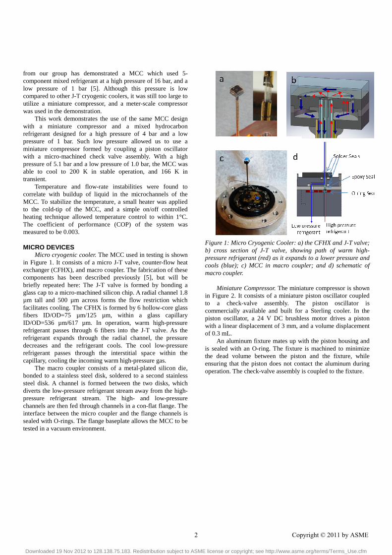
MICRO DEVICES Micro cryogenic cooler. The MCC used in testing is shown
in Figure 1. It consists of a micro J-T valve, counter-flow heat exchanger (CFHX), and macro coupler. The fabrication of these components has been described previously [5], but will be briefly repeated here: The J-T valve is formed by bonding a glass cap to a micro-machined silicon chip. A radial channel 1.8 µm tall and 500 µm across forms the flow restriction which facilitates cooling. The CFHX is formed by 6 hollow-core glass fibers ID/OD=75 µm/125 µm, within a glass capillary ID/OD=536 µm/617 µm. In operation, warm high-pressure refrigerant passes through 6 fibers into the J-T valve. As the refrigerant expands through the radial channel, the pressure decreases and the refrigerant cools. The cool low-pressure refrigerant passes through the interstitial space within the capillary, cooling the incoming warm high-pressure gas.
The macro coupler consists of a metal-plated silicon die, bonded to a stainless steel disk, soldered to a second stainless steel disk. A channel is formed between the two disks, which diverts the low-pressure refrigerant stream away from the high-pressure refrigerant stream. The high- and low-pressure channels are then fed through channels in a con-flat flange. The interface between the micro coupler and the flange channels is sealed with O-rings. The flange baseplate allows the MCC to be tested in a vacuum environment.
Figure 1: Micro Cryogenic Cooler: a) the CFHX and J-T valve; b) cross section of J-T valve, showing path of warm high-pressure refrigerant (red) as it expands to a lower pressure and cools (blue); c) MCC in macro coupler; and d) schematic of macro coupler.
Miniature Compressor. The miniature compressor is shown
in Figure 2. It consists of a miniature piston oscillator coupled to a check-valve assembly. The piston oscillator is commercially available and built for a Sterling cooler. In the piston oscillator, a 24 V DC brushless motor drives a piston with a linear displacement of 3 mm, and a volume displacement of 0.3 mL.
An aluminum fixture mates up with the piston housing and is sealed with an O-ring. The fixture is machined to minimize the dead volume between the piston and the fixture, while ensuring that the piston does not contact the aluminum during operation. The check-valve assembly is coupled to the fixture.
2 Copyright © 2011 by ASME
Downloaded 19 Nov 2012 to 128.138.75.183. Redistribution subject to ASME license or copyright; see http://www.asme.org/terms/Terms_Use.cfm

3 Copyright © 20xx by ASME
Figure 2: the miniature compressor composed of a miniature piston oscillator and micro-machined check valve assembly.
The check valves are composed of two layers of micro-
machined Kapton film, one bonded to each side of a stainless steel substrate, shown in Figure 3. A stainless steel substrate is necessary to allow the valves to be clamped and sealed by O-rings. L-shaped tethers and a through-hole were patterned into the Kapton using a reactive ion etch (RIE) process. A 10 µm polyimide adhesion layer is spin-coated onto the substrate to bond the Kapton film. To enhance the sealing of the valves against backflow leakage, a 13 µm metal gold ring is deposited about the through-hole on the substrate, thus allowing the valves to be pre-sealed when not biased by a pressure difference.
Figure 3: Micro valve assembly: a) schematic cross-section showing Kapton film, stainless steel substrate, and pre-sealing
ring; b) photograph of valve and zoom into L-tether and pre-sealing ring.
TESTING Test Setup. A schematic of the test setup is shown in Figure
4. The suction and discharge pressures of the miniature compressor were measured. The flow-rate of the refrigerant was monitored by a mass flow-meter, installed on the low-pressure side of the test-loop. A small platinum resistance thermometer (PRT) was mounted to the cold end of the MCC. The temperature was measured by applying a small voltage to the PRT, and measuring the current draw; the voltage was controlled to ensure that Joule heating in the PRT was below 0.1 mW. Pre-cooling of the refrigerant was facilitated by placing the MCC base in an ice bath, and a second PRT was mounted to the base of the MCC to monitor the base temperature. The MCC was held in a vacuum of <10-4 Torr during the cooling tests, to minimize heat loads associated with conduction through air. The pressure, temperature, and flow-rate data were recorded by a computer running LabVIEW. For compressor characterization tests, the MCC was replaced by a needle-valve to provide a variable flow resistance.
Figure 4: schematic of test setup.
Icing has been noted as a problem in MCCs [6], so to
ensure that any trace amount of water in the refrigerant was removed, 1 g of 3 Å molecular sieve was placed in the test loop. A 15 µm particulates filter was installed between the molecular sieve and the MCC to prevent any particulate build-up in the micro-channels. Before running any tests, the lines were evacuated to a pressure of <10-4 Torr, then charged with refrigerant from a low-pressure supply cylinder.
Refrigerant. The refrigerant used was a custom mixture
composed of light alkanes. The ideal cooling power of a refrigerant in a J-T cryogenic cooler is given by the product of flow-rate with the minimum isothermal enthalpy difference between the high-pressure refrigerant and low-pressure refrigerant [7]:
(1)
3 Copyright © 2011 by ASME
Downloaded 19 Nov 2012 to 128.138.75.183. Redistribution subject to ASME license or copyright; see http://www.asme.org/terms/Terms_Use.cfm

4 Copyright © 20xx by ASME
The composition (8% methane, 46% ethane, 14% propane, 4% butane, 26% pentane) was optimized by the program NIST4 [8] to provide a maximum (∆h|T)min in the range of 300 K to 200 K with a high pressure of 4.0 bar and a low pressure of 1.0 bar. The enthalpy curve is shown in Figure 5.
Figure 5: curve of isothermal enthalpy difference for the mixture with a high pressure of 4 bar and a low pressure of 1 bar. The minimum isothermal enthalpy difference is 4.09 kJ/mol in the temperature range 300 K – 200 K.
RESULTS AND DISCUSSION Compressor Characterization. The first test performed was
to characterize the compressor in terms of flow-rate and pressure generated. In these tests, the working fluid was N2, with an inlet pressure of 1.00 bar, at a temperature of 295 K. In this situation, the compressor was capable of producing a maximum pressure of 7.5 bar with no flow rate, or a maximum flow rate of 215 standard cc/min (sccm) with no pressure build up. Shown in Figure 6, the pressure vs. flow rate curve is linear between these two extremes. For an isothermal system, the efficiency of the compressor is given by the ratio of change in Gibb’s free energy to the energy drawn by the compressor. For N2 at 1 bar, the ideal gas law can be invoked, resulting in a compressor efficiency of the form:
(2)
where R is the universal gas constant, P is power used by the compressor, PL is inlet pressure, PH is outlet pressure, and T is the compressor temperature. Note also from Figure 8, the efficiency reaches a maximum value of 6.5% at a flow-rate of 150 sccm, and decreases as flow rate decreases. The desired pressure ratio of 4 occurs near the maximum efficiency.
Figure 6: The pressure ratio and efficiency as a function of flow-rate. Note that the maximum efficiency occurs at a flow-rate of 150 sccm.
Cooling Tests. The MCC was connected to the test setup, 1.25 bar of refrigerant was fed to the low-pressure side, and the system cooled as shown in Figure 7. During an initial charging period, the high-pressure and flow rate built up slowly. During that period, the cooling was slow. Eventually, the flow rate started to experience intermittent drops and jumps, and this was accompanied by rapid cooling. However, the low temperatures were not stable.
4 Copyright © 2011 by ASME
Downloaded 19 Nov 2012 to 128.138.75.183. Redistribution subject to ASME license or copyright; see http://www.asme.org/terms/Terms_Use.cfm

5 Copyright © 20xx by ASME
Figure 7: (a) the temperature profile and (b) flow rate as the MCC cools down. There is a 30 minute initial period where the flow rate builds up, followed by rapid cooling which accompanies instabilities in the flow rate. (c) Controlled heating was used to stabilize the temperature. With rapid cooling, the MCC could cool from 275 K to 200 K in 62 s.
Because the J-T valve of our MCC has a transparent top,
we were able to visualize the refrigerant during the unsteady flow period. It was found that the intermitted drops and jumps in flow rate were associated with a sudden build-up of liquid in the J-T valve, shown in Figure 8. Previous studies of hydrocarbon refrigerants in microchannels have shown that under certain conditions the refrigerant can form intermitted liquid slugs [9]. Although the specific conditions which lead to slug-flow are still a topic of research, it is likely that that is causing the instabilities in flow rate seen in our MCC.
Figure 8: 200 s of flow rate data collected while visualizing the cold-tip. Darker regions in the J-T valve are liquid, and lighter regions are vapor. The cold-tip fills with liquid during the periodic jumps in flow rate.
The unstable flow gives rise to unstable temperatures on
the cold tip of the MCC. These temperatures can be stabilized by using the PRT as a small heater in addition to a temperature sensor. By controlling the voltage applied to the PRT, one can briefly apply 15-25 mW of heat to the MCC whenever it crosses below a pre-defined temperature. In this manner, the temperature can be stabilized. With this technique we were able to demonstrate cooling to 200 K for over 1 hour, shown in Figure 7c.
Cooler Efficiency. The coefficient of performance (COP) of
the system is defined as the ratio of the heat lift at the cooler to the power input at the compressor. This value can be compared to the ideal COP, which for a J-T cryogenic cooler is the ratio of the minimum isothermal enthalpy difference with the change in Gibb’s free energy at the compressor:
(3)
Recall from Figure 6 that the compressor efficiency is quite low for the low flow rates seen during low-temperature cooling. The effect of compressor inefficiency can be removed by considering the performance of the cooler in terms of the ratio of the heat lift to the change in Gibb’s free energy at the compressor:
(4)
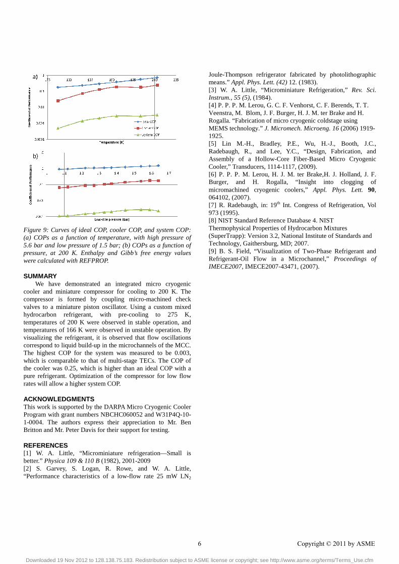
In Figure 9, the ideal COP, the COP of the system, and the COP of cooler are plotted as a function of both temperature and low-side pressure. The maximum COP of the cooler reaches 34% of the ideal COP at 191 K, with a value of 0.25. For comparison, highest ideal COP of any pure fluid in the same temperature range with the same pressures occurs for R-23 (chlorodifluoromethane) with a COP of 0.14. For our MCC, the maximum system COP is 0.003, which is comparable to the COP of multi-stage thermoelectric coolers for the same temperature range and heat lift. Our COP is expected to increase significantly with compressor optimization.
5 Copyright © 2011 by ASME
Downloaded 19 Nov 2012 to 128.138.75.183. Redistribution subject to ASME license or copyright; see http://www.asme.org/terms/Terms_Use.cfm
6 Copyright © 20xx by ASME
Figure 9: Curves of ideal COP, cooler COP, and system COP: (a) COPs as a function of temperature, with high pressure of 5.6 bar and low pressure of 1.5 bar; (b) COPs as a function of pressure, at 200 K. Enthalpy and Gibb’s free energy values were calculated with REFPROP.
SUMMARY We have demonstrated an integrated micro cryogenic
cooler and miniature compressor for cooling to 200 K. The compressor is formed by coupling micro-machined check valves to a miniature piston oscillator. Using a custom mixed hydrocarbon refrigerant, with pre-cooling to 275 K, temperatures of 200 K were observed in stable operation, and temperatures of 166 K were observed in unstable operation. By visualizing the refrigerant, it is observed that flow oscillations correspond to liquid build-up in the microchannels of the MCC. The highest COP for the system was measured to be 0.003, which is comparable to that of multi-stage TECs. The COP of the cooler was 0.25, which is higher than an ideal COP with a pure refrigerant. Optimization of the compressor for low flow rates will allow a higher system COP.
ACKNOWLEDGMENTS This work is supported by the DARPA Micro Cryogenic Cooler Program with grant numbers NBCHC060052 and W31P4Q-10-1-0004. The authors express their appreciation to Mr. Ben Britton and Mr. Peter Davis for their support for testing.
REFERENCES [1] W. A. Little, “Microminiature refrigeration—Small is better.” Physica 109 & 110 B (1982), 2001-2009 [2] S. Garvey, S. Logan, R. Rowe, and W. A. Little, “Performance characteristics of a low-flow rate 25 mW LN2
Joule-Thompson refrigerator fabricated by photolithographic means.” Appl. Phys. Lett. (42) 12. (1983). [3] W. A. Little, “Microminiature Refrigeration,” Rev. Sci. Instrum., 55 (5), (1984). [4] P. P. P. M. Lerou, G. C. F. Venhorst, C. F. Berends, T. T. Veenstra, M. Blom, J. F. Burger, H. J. M. ter Brake and H. Rogalla. “Fabrication of micro cryogenic coldstage using MEMS technology.” J. Micromech. Microeng. 16 (2006) 1919-1925. [5] Lin M.-H., Bradley, P.E., Wu, H.-J., Booth, J.C., Radebaugh, R., and Lee, Y.C., “Design, Fabrication, and Assembly of a Hollow-Core Fiber-Based Micro Cryogenic Cooler,” Transducers, 1114-1117, (2009). [6] P. P. P. M. Lerou, H. J. M. ter Brake,H. J. Holland, J. F. Burger, and H. Rogalla, “Insight into clogging of micromachined cryogenic coolers,” Appl. Phys. Lett. 90, 064102, (2007). [7] R. Radebaugh, in: 19th Int. Congress of Refrigeration, Vol 973 (1995). [8] NIST Standard Reference Database 4. NIST Thermophysical Properties of Hydrocarbon Mixtures (SuperTrapp): Version 3.2, National Institute of Standards and Technology, Gaithersburg, MD; 2007. [9] B. S. Field, “Visualization of Two-Phase Refrigerant and Refrigerant-Oil Flow in a Microchannel,” Proceedings of IMECE2007, IMECE2007-43471, (2007).
6 Copyright © 2011 by ASME
Downloaded 19 Nov 2012 to 128.138.75.183. Redistribution subject to ASME license or copyright; see http://www.asme.org/terms/Terms_Use.cfm