dem 122032b – syh-ly...cl, fr, m/s and res pins 4. a0, e, r/w, cs, cl, res, m/s pins dem 122032b...
TRANSCRIPT
23/April/2007
Display Elektronik GmbH
DEM 122032B – SYH-LY
LCD MODULE
Product specification Version : 1
DOCUMENT REVISION HISTORY Version DATE DESCRIPTION CHANGED BY
00 Sep-5-2006 First issue 01 Sep-5-2006 Change print

CONTENTS 1. Functions & Features 1 2. Mechanical specifications 1 3. Block diagram 1 4. Dimensional Outline 2 5. Pin description 3 6. Maximum absolute limit 4 7. Electrical characteristics 5 8. Timing Characteristics 5 9. Control and display command 6 10. Backlight characteristics 7 11. Electro-Optical characteristics 7 12. PRECAUTIONS OF LCD/LCM 8
DEM 122032B SYH-LY Product Specification
VERSION: 1 PAGE: 1
1. FUNCTIONS & FEATURES 1.1. Format : 122x32dots 1.2. LCD mode : STN / Positive transflective mode / Yellow-green 1.3. Viewing direction : 6 o’clock 1.4. Driving scheme : 1/32 Duty cycle, 1/5 Bias 1.5. Power supply voltage(VDD) : 5.0 Volt (typ.) 1.6. LCD driving voltage : 4.8 Volt (typ.) 1.7. Operation temp : -20 ~ 70°C 1.8. Storage temp : -30 ~ 80°C 1.9. Backlight : LED, Yellow-green, Lightbox
2. MECHANICAL SPECIFICATIONS 2.1. Module size : 84.0 x 44.0 x 13.5 mm(max.) 2.2. Viewing area : 61.0 x 19.5 mm 2.3. Dot pitch : 0.44 x 0.49 mm 2.4. Dot size : 0.40 x 0.45 mm
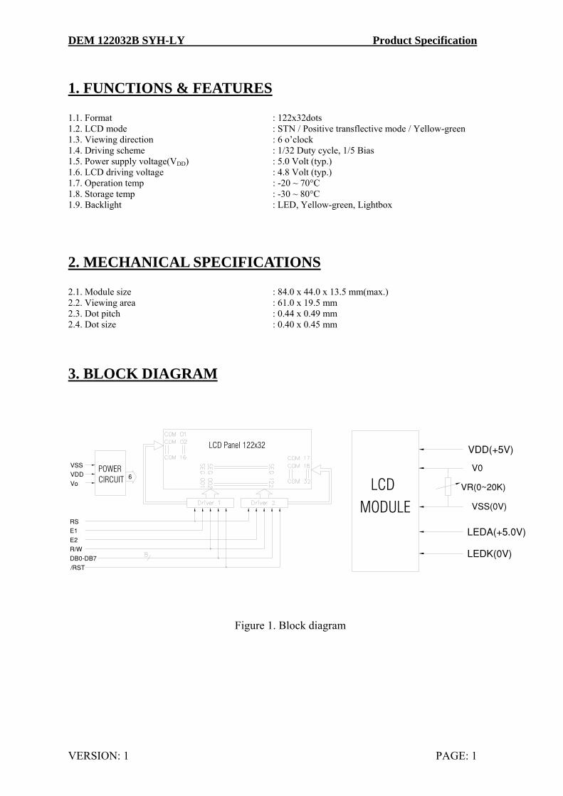
3. BLOCK DIAGRAM
DB0−DB7
VDD
R/W
/RST
E1
E2
RS
Vo
VSS V0
VDD(+5V)
VSS(0V)
LEDK(0V)
LEDA(+5.0V)
VR(0~20K)
POWER CIRCUIT 6
LCD Panel 122x32
MODULELCD
Figure 1. Block diagram
DEM 122032B SYH-LY Product Specification
VERSION: 1 PAGE: 2
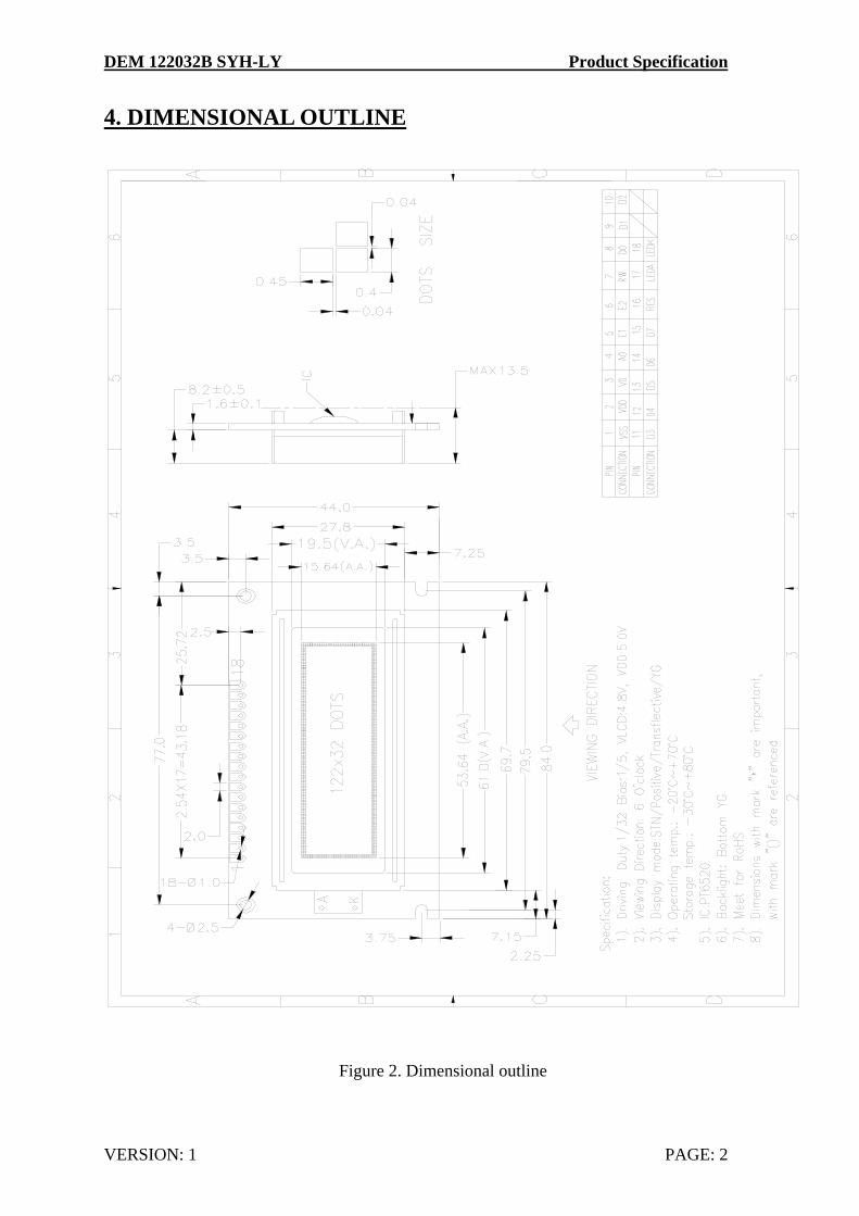
4. DIMENSIONAL OUTLINE
Figure 2. Dimensional outline
DEM 122032B SYH-LY Product Specification
VERSION: 1 PAGE: 3
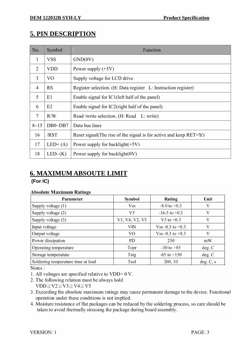
5. PIN DESCRIPTION No. Symbol Function
1 VSS GND(0V)
2 VDD Power supply (+5V)
3 VO Supply voltage for LCD drive
4 RS Register selection. (H: Data register L: Instruction register)
5 E1 Enable signal for IC1(left half of the panel)
6 E2 Enable signal for IC2(right half of the panel)
7 R/W Read /write selection. (H: Read L: write)
8~15 DB0~DB7 Data bus lines
16 /RST Reset signal(The rise of the signal is for active and keep RET='h')
17 LED+ (A) Power supply for backlight(+5V)
18 LED- (K) Power supply for backlight(0V)
6. MAXIMUM ABSOUTE LIMIT (For IC)
DEM 122032B SYH-LY Product Specification
VERSION: 1 PAGE: 4
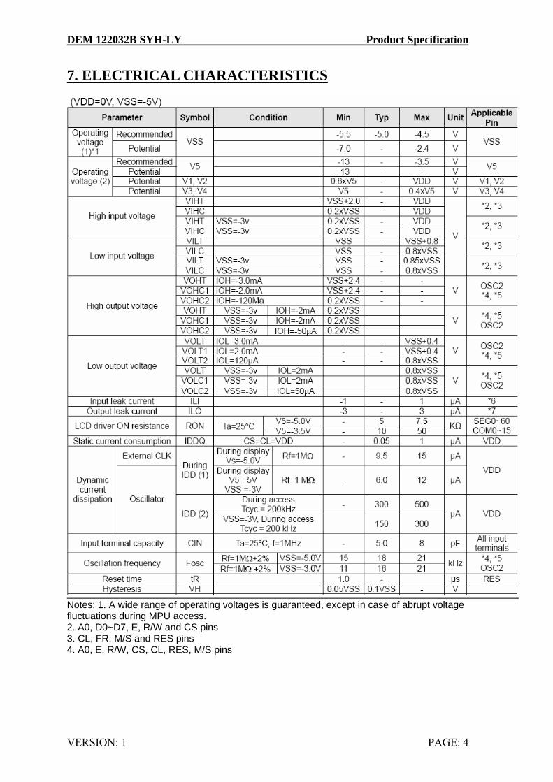
7. ELECTRICAL CHARACTERISTICS
Notes: 1. A wide range of operating voltages is guaranteed, except in case of abrupt voltage fluctuations during MPU access. 2. A0, D0~D7, E, R/W and CS pins 3. CL, FR, M/S and RES pins 4. A0, E, R/W, CS, CL, RES, M/S pins
DEM 122032B SYH-LY Product Specification
VERSION: 1 PAGE: 5
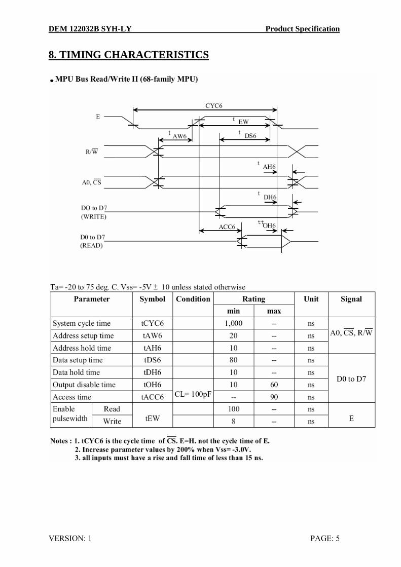
8. TIMING CHARACTERISTICS
DEM 122032B SYH-LY Product Specification
VERSION: 1 PAGE: 6
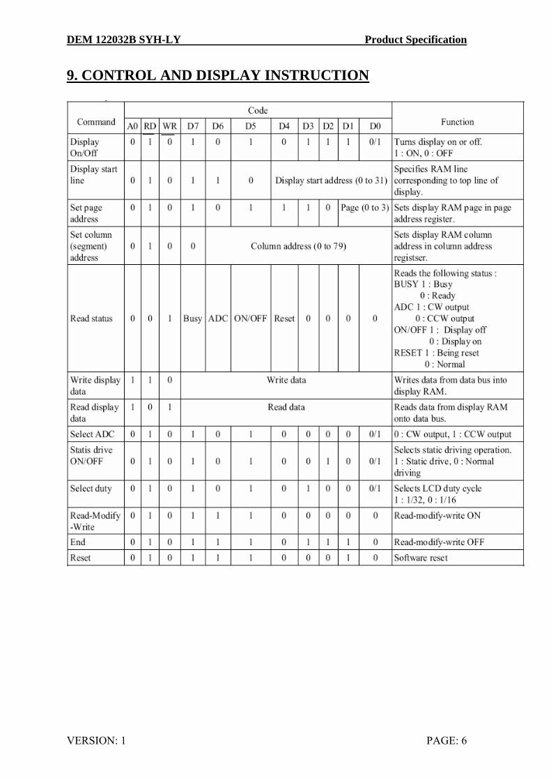
9. CONTROL AND DISPLAY INSTRUCTION

DEM 122032B SYH-LY Product Specification
VERSION: 1 PAGE: 7
10. BACK LIGHT CHARACTERISTICS LCD Module with bottom Backlight ELECTRICAL RATINGS
Ta = 25°C
Item Symbol Condition Min Typ Max Unit Forward Voltage VF IF=100mA 3.85 4.05 4.25 V Reverse Current IR VR=8V --- --- 1 mA Luminous Intensity (With LCD dots off)
IV IF=100mA 125 179 --- Cd/m2
Wave length λρ IF=100mA 568 nm Color Yellow-green External use at pin 17/18 5 Volt with approx. 140mA (typ.)
11. ELECTRO-OPTICAL CHARACTERISTICS
( VOP =4.8V, Ta = 25°C ) Item Symbol Condition Min Typ Max Unit
Ta = -20°C 5.0 5.2 5.4 Ta = 25°C 4.6 4.8 5.0 Operating Voltage
Vop
Ta = 70°C 4.2 4.4 4.6 V
Tr --- 185 --- ms Response time Tf Ta = 25°C --- 200 --- ms Contrast Cr Ta = 25°C --- 4 --- ---
θ -40 --- +40 deg Viewing angle range
Ф Cr≥ 2 -40 --- +40 deg
DEM 122032B SYH-LY Product Specification
VERSION: 1 PAGE: 8
12. PRECAUTION FOR USING LCD/LCM LCD/LCM is assembled and adjusted with a high degree of precision. Do not attempt to make
any alteration or modification. The followings should be noted. General Precautions: 1. LCD panel is made of glass. Avoid excessive mechanical shock or applying strong pressure onto the
surface of display area. 2. The polarizer used on the display surface is easily scratched and damaged. Extreme care should be
taken when handling. To clean dust or dirt off the display surface, wipe gently with cotton, or other soft material soaked with isoproply alcohol, ethyl alcohol or trichlorotriflorothane, do not use water, ketone or aromatics and never scrub hard.
3. Do not tamper in any way with the tabs on the metal frame. 4. Do not make any modification on the PCB without consulting DISPLAY. 5. When mounting a LCM, make sure that the PCB is not under any stress such as bending or twisting.
Elastomer contacts are very delicate and missing pixels could result from slight dislocation of any of the elements.
6. Avoid pressing on the metal bezel, otherwise the elastomer connector could be deformed and lose contact, resulting in missing pixels and also cause rainbow on the display.
7. Be careful not to touch or swallow liquid crystal that might leak from a damaged cell. Any liquid crystal adheres to skin or clothes, wash it off immediately with soap and water.
Static Electricity Precautions: 1. CMOS-LSI is used for the module circuit; therefore operators should be grounded when ever he/she
comes into contact with the module. 2. Do not touch any of the conductive parts such as the LSI pads; the copper leads on the PCB and the
interface terminals with any parts of the human body. 3. Do not touch the connection terminals of the display with bare hand; it will cause disconnection or
defective insulation of terminals. 4. The modules should be kept in anti-static bags or other containers resistant to static for storage. 5. Only properly grounded soldering irons should be used. 6. If an electric screwdriver is used, it should be grounded and shielded to prevent sparks. 7. The normal static prevention measures should be observed for work clothes and working enches. 8. Since dry air is inductive to static, a relative humidity of 50-60% is recommended. Soldering Precautions: 1. Soldering should be performed only on the I/O terminals. 2. Use soldering irons with proper grounding and no leakage. 3. Soldering temperature: 280°C+10°C 4. Soldering time: 3 to 4 second. 5. Use eutectic solder with resin flux filling. 6. If flux is used, the LCD surface should be protected to avoid spattering flux. 7. Flux residue should be removed.
DEM 122032B SYH-LY Product Specification
VERSION: 1 PAGE: 9
Operation Precautions: 1. The viewing angle can be adjusted by varying the LCD driving voltage Vo. 2. Since applied DC voltage causes electro-chemical reactions, which deteriorate the display, the applied
pulse waveform should be a symmetric waveform such that no DC component remains. Be sure to use the specified operating voltage.
3. Driving voltage should be kept within specified range; excess voltage will shorten display life. 4. Response time increases with decrease in temperature. 5. Display color may be affected at temperatures above its operational range. 6. Keep the temperature within the specified range usage and storage. Excessive temperature and
humidity could cause polarization degradation, polarizer peel-off or generate bubbles. 7. For long-term storage over 40°C is required, the relative humidity should be kept below 60%, and
avoid direct sunlight. Limited Warranty DISPLAY LCDs and modules are not consumer products, but may be incorporated by DISPLAY’s customers into consumer products or components thereof, DISPLAY does not warrant that its LCDs and components are fit for any such particular purpose. 1. The liability of DISPLAY is limited to repair or replacement on the terms set forth below. DISPLAY
will not be responsible for any subsequent or consequential events or injury or damage to any personnel or user including third party personnel and/or user. Unless otherwise agreed in writing between DISPLAY and the customer, DISPLAY will only replace or repair any of its LCD which is found defective electrically or visually when inspected in accordance with DISPLAY general LCD inspection standard . (Copies available on request)
2. No warranty can be granted if any of the precautions state in handling liquid crystal display above has been disregarded. Broken glass, scratches on polarizer mechanical damages as well as defects that are caused accelerated environment tests are excluded from warranty.
3. In returning the LCD/LCM, they must be properly packaged; there should be detailed description of the ailures or defect.