delphi facility investigative report appendix a … · delphi facility investigative report...
TRANSCRIPT
DELPHI
FACILITY INVESTIGATIVE REPORT
APPENDIX A SECTION 2
SITE CHARACTERISTIZATION AND REMEDIAL ACTION PLAN 2-38
SITE CURACTERIUTION AND REMEDIh ACTION PLAN DELCO-REMY A N m I M , CALIFORNIA
BARBARA, CALIFORNIA JOB NO. 14191-002-042 IQOOeMBER 4, 1986

be lco-Remy 1201 U. Magnolia * Anaheim, California DRAFT Attention: W. Dave Hornyak
Re: Sire Characterization and Remedial Action Plan
Dear Mr. Hornyak:
Please find attached our draft Site Characterization and Remedial Action Plan for Delco-Remyl.a facility.' This document summarizes the work conducted at the rite to date, discurres the extent of contaaination, and presents a reme- dial action plan. After your review, this docliment can be submitted to the Orange County Health Care Agency personsel listed belov. Work can be scheduled and implemented after the counties review and concurrence of the proposal plan.
After you have reviewed the document please contact the undersigned if you have co-ente or questions.
Very truly yours
DAMES 6 Z(O0RE
Anthony S. Nelson Project Manager ~tgistered Gcologiat 4175
f 1.0 INTRODUCTION
9
1.1 PURPOSE
The purpose of the following report is to: (1) present the results of our i i ;
Site Characterization Plan; and ( 2 ) propose remedial actions to address the !
contaminat ion.
1.2 BACKGROUND
A t the request of Delco-Remy, Dames b Yoore is providing conrulting serv-
ices related to .the removal of s i x underground storage tanks at 1201 North
Hagnolia Blvd., Anaheim, California (Figure 1).
In January 1985 representatives of Dames 6 Moore and Delco-Remy agreed on
a preliminary scope of servic-s to include: ( 1 ) soil sampling under each tank;
(2 ) analysis of samples; ( 3 ) interaction with regulatory agencies;
( I ) assistance ic preparing permits; and, ( 5 ) assistance in developing a site
characterization plan if needed. In July 1986 these services were expanded to
include drilling and sampling of soils to characterize soil contamination
obrerved during the tank removal program. Dames & Moore arranged for drilling
to be coaducted by Datum Exploration Company from Long Beach and for chemical
terting servicee to be provided by Chemical Research Laborstorier in Stanton,
California. Delco-Remy arranged for the tank excavations to be conducted by
Frize Corporatioa from Indurtry, California; for handling of the vaste materi-
als by Waste Dirposal Service8 of Upland Califoraia; and for rewval of residu- i
a1 fuel by Petro-Trading of Long Beach, California.
1.3 FACILITPES 1
The Delco-Remy facility coaeirts of a main manufacturing building and
7, .- aumtrous smaller buildings and related rupport operation8 . The principal ac ti- $ v i ty at the Delco-Rely facility is the assaably aad dirtrlbutfoa of lead/acid
battcricn.
.. -..- ---" --.---.--. ---.-
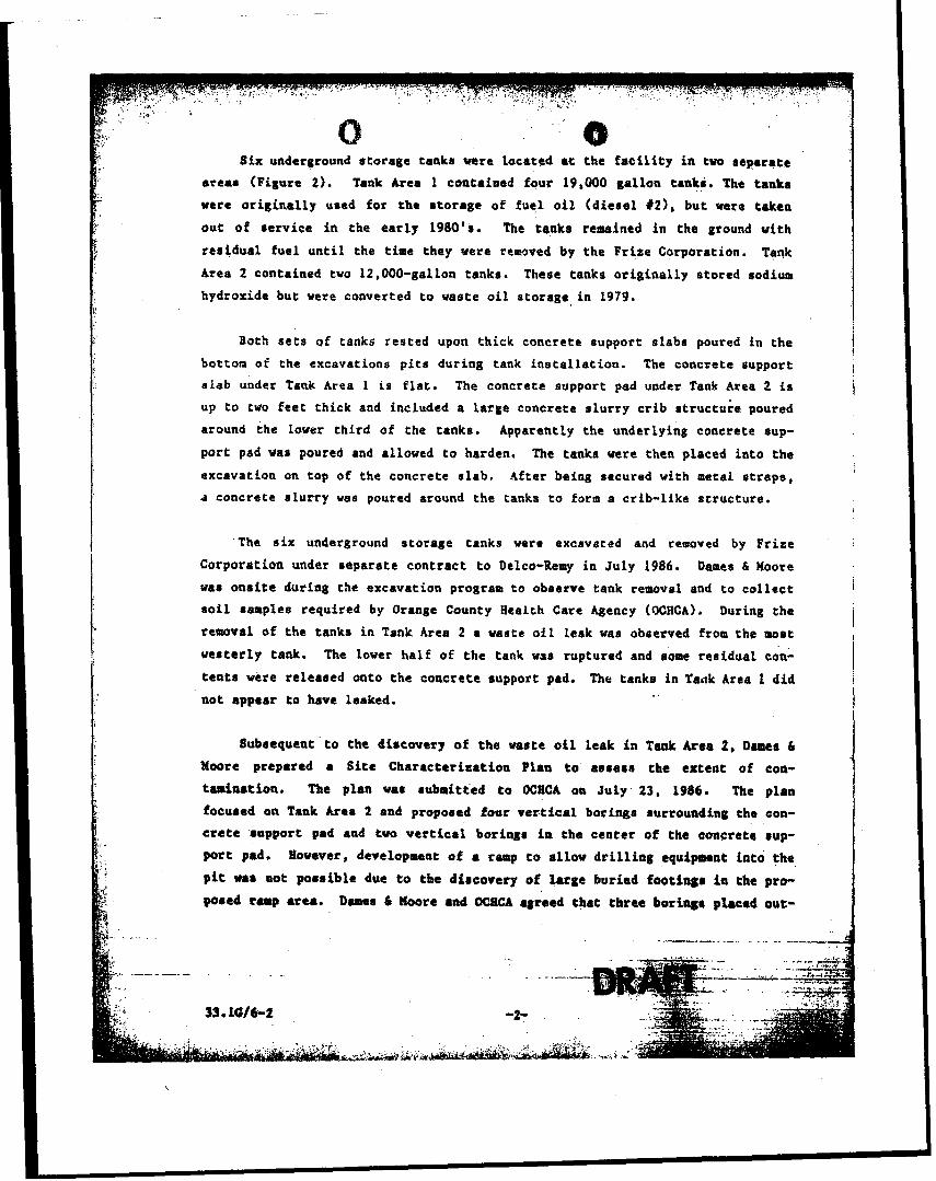
S5x underground r torage tankr vere Located a t the f a c i l i t y i n two reparate
a r ea s (Figure 2). Tank Area 1 contained four 19,000 gal lon tanka. The tanka I were o r ig ina l l y used for t he r to rage of fue l o i l ( d i e s e l #2) , but -vere taken
out of re rv ice i n the e a r l y 1980'8. The tanks remained i n the ground with
r e s idua l fuel u n t i l the time they were removed 'by t he Fr ize Corporation. Tank
Area 2 contained tvo 12,000-gallon tanks. These tanks o r ig ina l l y s tored sodium
hydroxide but: vere converted t o vaate o i l s torage i n 1979.
Both s e t s of tanks rested upon thick concrete support s labs poured i n the
bottom of the excavations p i t s during tank i n s t a l l a t i on . The concrete support i
siab under Tank Area 1 i s f l a t . The concrete support pad under Tank Area 2 is
up t o two f e e t thick and included a Large concrete s l u r r y c r i b s t ruc tu re poured I
around the lower t h i rd of the canks. Apparently the underlying concrete sup-
port ped was poured and allowed t o harden. The tanks vere then placed i n to the
excavation on top of the concrete s l ab . After being secured with metal s t r aps ,
a concrete s l u r r y was poured around the tanks t o form a cr ib- l ike s t ruc ture .
The s i x underground atorage tanks vere excavated and recrroved by Fr i ze .
Corporation under separa te cont rac t t o Delco-Bemy i n Ju ly 1986. Da~lcs & Moore
war o n s i t e during the excavation program t o oboeme tank removal and t o co l l ec t i
s o i l ramplee required by Orange County Health Care Agency (OCHCA). During the
removal of the tanks i n Tank Area 2 a vaste o i l leak was observed from the most i
v e s t e r l y tank. The Lover ha l f of t he tank war ruptured and rome res idua l con- I t e n t s were released onto t he concrete support pad. The tanks i n Taak Area 1 d id
not appear t o have leaked. . . i I
Subsequent ' t o t he discovery of t he va r t e o i l leak i n Tank Area 2, Demtr 6
Moore prepared a S i t e Cha rac t e r i t a t i on Plan t o as re ra t he extent of coa-
tamination. The plan vas submitted t o OCUCA on Ju ly 23, 1986. The plan
f o c u ~ e d on Taak Area 2 and proporred four v e r t i c a l boringo rurrounding the con-
c r e t e .support pad and tvo v e r t i c a l boriagr i n the cen te r of the concrete rup-
footing# i n the pro-
e boriagr placed out-
.,. .--.. -.A . . . . . . . - . -. , -.-

ride the excavation pit and angle-drilled under the pad and one vertical
exploratory boring arilled through the concrete pad would be used to collect
soil samples. Additionally, one ground water monitoring well vould be
installed just southwest of Tank Area 2.
Three sets of samples vere collected during the coarse of the invesciga- I
tion. The first set of soil samples were rollectcd dur ing tank removai (G1
and G9). The second 3e t soil of samples *ere ?oliected in Tank Area 2 from I borings in and around the excavation pic (81 t:, 8 4 , MW: to MJ4 and HBl 1 samples). After chemical testing, a third set of soil samples (HB2 and H B 3 ) 1 vere collected to further assess soil contamination. Sampling methods, loca-
tions and results are discussed below.
I 2.0 GEOLOGIC AND HYDROLOGIC SETTING
Regional geologic srructures in the area include the Whictier-Elsinore
fault system on the northeast side of the Orange County and the
Ncwport-Inglewood fault zane along the 'coastline . These faults are associated
primarily with right lateral horizontal displacement. Topographic relief com-
monly characterizes their traces. The Orange County Plain overlies a large
northwest-southeast trending synclinal trough that extends from the San Joaquin
hills near Nevport Beach to the Sanca Monica mountains northwest of Lo8
Aagcles. Subsidence in this structural basin was initiated 'in Middle Miocene
time and received up to 28,000 feet of sedimqnt along the western edge of the
county.
The study area is located in the northern part of the Orange County
Coastal Plain and is locally underlain by a thick sequence of poorly consoli-
'dated to unconsolidated sand, gravel and fine-grained sediments of continental
origin. The sediments vere deposited by rivers draining highland areas to the
north and transporting sediment west and southweatuard~ across the Orange Coaty
Plain. Rivets aeatby include the S m t r Ana River, 64 miles to the vent, Carbon
Creek 1s rilas to the routh, and Coyote Creek 5.2 miles to the w e t . Aliuvial . .-...---.--- .- .
depoaits are generally dcrctibed 88 widely variable rixturas of .,~8yat8, rand* ,

and a i l t r . Poorly conaolidactd sediments encountered during exploratory
d r i l l i n g s onr i ta consis ted of medium t o f ine .grained rand8 w i t h l ayer r of randy
s i l t and r i l t g sands.
The r i t e i s s i t ua t ed i n t he lower Santa Ana River Ground Water Basin. The
basin is ac tua l l y part of a l a rge r ground water basin t h a t underl ies both the
Los Angeles and Orange County Coastal Plains. Well records ind ica te t ha t the
regional ground water t a b l e , used fo r domestic water supply, occura approxi-
mately 100 f ee t below ground sur face i n the s i t e a rea . Orange County Water
D i s t r i c t reporc Prom 1984-85 ind ica tes a southvescer ly flow d i r ec t i on For t h i s
water t ab le . Shallow, perched water, is reported t o occur approximately 30 t o - *-.. 40 fsct below ground sur face (bgr) i n rhe Anaheim area. Shallow ground water
vas encountered under Tank Area 2 a t 31 feet bgr during t h i e inves t iga t ion .
Ground va t e r qua l i t y i n the perched water is general ly considered very
poor. Recent publ icat ions by Robbina (1986) repor t s concentrat ions of t o t a l
dissolved so l i d s i n excess of severa l thousand milligrams per l i t e r . Water
wel ls i n tJI. area do not u t i l i z e the shallow perchcd water. Ground water qual-
i t y i n the deeper producing zone i n the Anaheim area genera l ly exh ib i t s good t o
excc l l rnc qua l i ty . However, values up to 600 milligrams per l i t e r for t o t a l
dirsolved so l i d s and up t o 325 tcill igramr per l i t e r f a r hardness have been
reported i n Anaheim.
3.1 TANK EXCAVATLON AND SOIL SAMPLING I Prior to t he excavation of any tank, the tank contenta e r e evacuated and I
tanks we& r insed i n place by Petro-Trading and Diaposal Control Servicer under { t he d i r ec t i on of Delco-Remy. The r i n r a t e was removed and dry ce war inser ted
. . i n t o t he tanka at a r a t i o of t en pound8 to every thousand gal lonr . The tanka
were then excavated and removed Lrm the ground during a rvo-day period by
I b
. . F r i i e Corporation. Tank remova? was witnessed by Miss Debby Greco of qCHCA and
l a rpec to r Ray Martin of t he Anaheim F i r e Department. Subrequent to e r c k a t i o o
the tank8 were removed t o a rur face ataging area. The tankr m t e iaipected by
E 1 r e p r e r t n t a t i v e of t h e Anaheim l i r e Department. The moat w a t e r 1 7 trak ia .Tank $4:: . ..-.. . ..__.-_- I-. --.. ._i--.-.-- .-
-?? . . .,.: -- :.: ,,. 2 ; . . ,.?.. ' . ' ''?- ,:-. . .*.,.-!:, ..?,y:?l . , , . . ,. .-. .. . : . . . 7 ; . ;.," . , . . A ' .
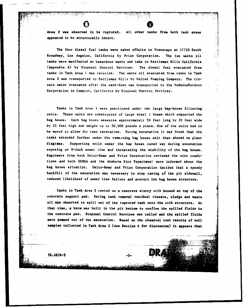
Area 2 vas obrerved t o be ruptured. A l l o ther tanks from both tank ageas
appeared t o be i l t ruc tura l ly i n t a c t ,
The four d i e se l fue l tanka vere taken o f f s i t e t o Transcape a t 17710 South
Broadway, Los Angeles, Ca l i forn ia by Prize Corporation. The two waste o i l
tanks were manifested a s hazardous waste and take t o Kettleman H i l l s Ca l i forn ia
(Appendix A) by Disposal Control Services. The d i e s e l fue l evacuated from
tanks i n Tank Area 1 vas recycled. The waste o i l evacuated from tanks i n Tank
Area 2 was transported tc Kettleman H i l l s by United Pumping Company. The t in -
s a t e va t e r evacuaced a f t e r the wash-down was t ransported t o the DeHennoKerdoon
Corporation i n Cornpton, Cal i forn ia by Disposal Control Services.
Tanks i n Tank Area 1 vere positioned under two l a rge bag-house f i l t e r i n g
un i t e . These un i t s a re constructed of large s t e e l I beams which supported the
bag house. Each bag house measures approximately 50 f ee t long by 30 f e e t wide
by 25 feet high and weighs up t o 50,000 pounds a piece. One of the un i t s had t o
be moved t o a l l o v fo r tank excavation. During excavation i t was found t h a t the
tanks extended fur ther under the remerning bag houee un i t than shoved on plane
diagrama. Supporting s o i l s under the bag houee caved vay during excavation
exposing an 8-inch newer l i ne and threatening t he s t a b i l i t y of t h e bag house.
Engineers from both Delco-Remy and P r i ze Corporation reviewed the s i t e condi-
t i o n s and both OCHCA and the Anaheim Fi re Departman? were informed about the
beg house s i t ua t i on . Delco-Remy and Fr ize Corporation decided t ha t a speedy
b a c k f i l l o f t he excavation was neceseary t o s top caving o f ' t h e p i t s i d e v a l l ,
reduced l ike l ihood of sewer l i n e f a i l u r e and p ro t ec t t he bag hause s t ruc ture .
Tanks i n Tank Area 2 res ted on a concrete s l u r r y c r i b housed on top of t he
concre te support pad. During tank removal r e s idua l r i n r a t e , sludge and v a r t e
o i l w a r obwrved t o s p i l l ou t of t he ruptured tank onto the c r i b s t ruc ture . A t
t h a t time, a berm was b u i l t in the p i t bottom t o confine t he s p i l l e d fluida t o
the concrete pad. Disposal Coutrol Servicea war c a l l e d and the s p i l l e d f l u i d s
were pumped out of the excavation. Baaad on the chemical t e a t r e r u l t a of roil sample8 co l lec ted i n Tank Area 2 ( see Section 4 f o r d i r cu r r i oa ) it 8ppeara that

r i n r a t e water and vas t e o i l ercaped t o the edgc*.of t he concrete pad and pane-
t raced the shallow s o i l s t o an approximate deikh of two f e e t iaunadtattly sur- 1 rounding the pad a rea on the north.
After removal oE the tanka, grab samplee were co l lec ted from s o i l s below
each tank. Since a l l tanks res ted d i r e c t l y on concrete , samples could not be
obtained d i r e c t l y under the tank inver t s . Spec i f ic s o i l s sample locat ions vere
discussed with Miss Debbie Greco of OCHCA. The eamplee were co l lec ted from
s o i l s betxeen the tanks or from a o i l s immediately a t the edge o f the concrete
pads.
So i l samples G-2, G-3 and G-6 i n Tank Area 2 vere co l lec ted approxiwte ly
tvo f e e t below the edge of t he concrete support s l a b uaing a backhoe. Samples
G-5 and G-9 i n Tank Area 2 and samples 0-6, 0-7 and G-8 i n Tank Area 1 were
co l lec ted by using a spade t o expose fresh s o i l s i n t he p i t bottom and quickly
placing the sample i n to a wide mouth jar . Sample C-1 was co l lec ted from s o i l
p i l e s excavated from Tank Area 2 and s tored above ground.
A l l s o i l grab samples were placed i n wide mouth ja rs . The s o i l was tapped
firmly i n t o t he jar, t o reduce head apace. The jars were sealed. labeled,
placed i n a cooler with dry i c e and del ivered t o the chemical t e s t i n g labora-
t o ry on t he day of co l lec t ion . Grab sample loca t ions a r e shovn i n Figures 2
and 3, t he r e r u l t ~ of the ana lys i s a r e presented i n Appendix C and discussed i n
Sect ions 4.0 and 5.0. I a
3.2 DRILLING AND SOIL SWLIUG i A11 d r t l l i n g warn conducted under the technical rupervirior; of a . Dames &
completed manualfy. S o i l samples uere eo l lec tcd a t +foot i a t e r v d r , . coppdnc~
. . . . . . . . .- - - , . ..- - - -

stem of the auger using a modified Dames €I Moore U-type aampler (~ppend ix 8):
The sampler was driven 12 inches or t o re fusa l with a standard 140 pound
hammer. Samples vere retr ieved fyom the hand augered boring by manually driv-
ing the Dames 6 Moore sampler t o 12 inches. The samplers vere f i t t e d with
2.5-inch diameter, 3-inch iang s t a i n l e s s s t e e l s leeves. So i l samples were
screened fo r organic \ apors using a TLV or Unu vapor monitor. The lower-most
dample sleeves were retained f o r chemical t e e t i n s . Exposed s o i l a t the end of
each sample sleeve was covered with tef lon sheet ing, f i t t e d v i th p l a s t i c end
caps , and sealed with tape. Labels were fixed t o the end cap J E each sample
and contained: boring aumber; sample number; depth; da t e ; c o l l e c t o r ' s name;
owner; and, location. Samples were placed in coolers with dry ice and were
de l ivered , v i t h chain of custody forms (Appendix C ) t o the laboratory on the
day of co l lec t ion . A log of the material oncountered i n the boring was
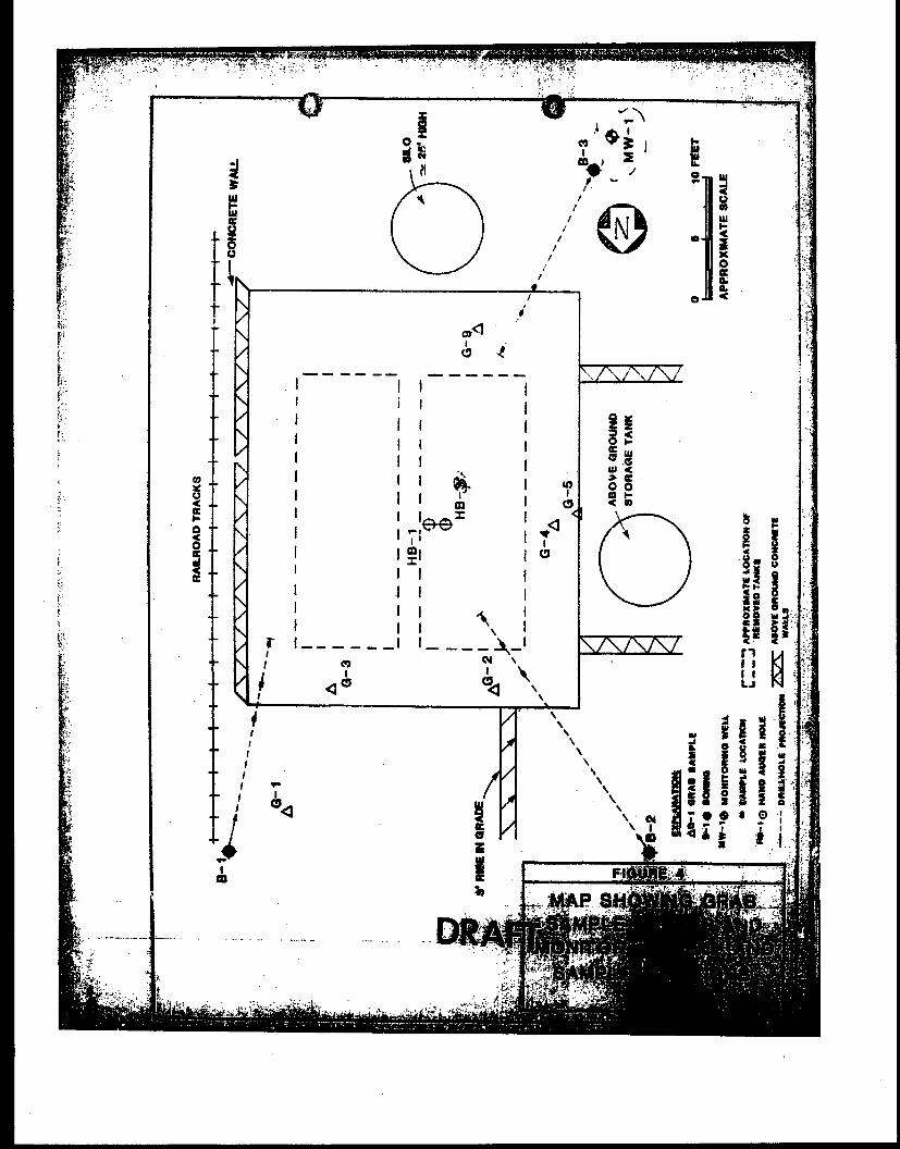
recorded and i s presented i n Appendix R. Borinz l o c a t i ~ n s are shown i n Figure
3 and 4.
A l l dovnhole d r i l l i n g equipment was steam cleaned p r io r t o use a t each
boring locat ion. Pr ior t o the co l lec t ion of each sample, s o i l ample equipment
end s t a i n l e s s s t e e l sample s leeves bcre waahed i n d i l u t e trisodium phosphate
so lu t ion , r insed in fresh water, and f i n a l rinsed in d i s t i l l e d water. Dr i l l i ng
cu t t ings vere placed with above ground contaminated s o i l ons i t e . An admixture
of bentonite (Volclay or Bolaplug) and sand was used t o b a c k f i l l the borings.
3.3 INITALLATION OF GROUND MONITORING WELL AND GROUNDWATER SAXPLING
Oac ground water monitoring well wag installed southwest of Tank Area 2 t o
ar8ess the depth t o perched ground water and t o c o l l e c t ground water ramples
for chemical tearing (Figure 4).
The well was d r i l l e d with a ten-inch, hollow-stem auger equipment t o a depth of 38 Zeet. A ten foot length of 4-inch, rehadule 40, rlottad, capped

foot thick clay pellet plug was then installed above the sand. The rewining
annular @>ace was filled with a concrettlbentonite grout to the ground surface.
The well was completdd with a PVC locking hasp cover installed in 8 rtandard
concrete christy box with locking tab and steel plate. The chriety box was
installed at grade.
After installation the well was allowed t o equilibrate for a period of one i
veek. The vell was then manually purged of t.hree well volumes using a teflon
bailer. The purged water was placed in a 55-gallon drum on site pending analy-
ses of the samples. Ground vater samples were then collected v i f h a teflon
Sailer and were placed in VOC bottles. The samples were properly labeled,
placed in s cooler snsite, and delivered t c the Laboratory on the day of
ccllactioa. A second set of ground water samples were collected October 15, i 1996 using the same method.
3.4 CHEMICAL TESTING ,
Chemical teoting was performed by Chemical Research Laboratories of
Stanton, California. Chemical test method 418.1 was propoeed for all rail ram-
plea -in our Site Characteriratioa Plea. Subsequent to Giscussicns between
Dames 6 Moore and OCXCA the-plea was Gdified to include ground vatrrr~u~~f@#
- z ~ ~ ~ . ' ~ i i h a d _,+_ .* . . . 601 and croil analysis using EPA Method -8015, 8248':iiiii'IZ?@~,~&?~ - . - . .---. ---__ *q.. s*: c r: - -, .
t*d.$<PZ iaaplee as discuesed below. Figur:: 3, 4 and 5 show the sample ' 3
locet ions.
Soil grab ramples collected from both Tank Area8 1 and*'2, and undirturbed
roil samples co:lected from exploratory boringr, in Tank Area 2 were analyzed 1
m hydrocarbon (TPB) using Method 418.1.
t
Subrequent to chemical testing by Hethod.418.1 tvo additional roil ramplea , :
were collected and analyzed to further aerese the contamination.- S ~ p l r t
HB-2-18, caLlected by hand augering in Tank Area 1, was rrurlyted fqr ~eadt f tc

Groundwaf er eampler eollec ted Augue t 25 ; '1986; from the monitoring vall I inrealled eouthweet of tank area 2 vere anelysed iar purgeable t~alacarbons I using EPA Method b01. The groundwater ~amples collected October 16th, 1986, I were anelyrea for extractable organic compounds using EPA Hetbod 625.
*..-- -- 4 . 0 ANALYTICAL BESULTS
1 Grab sample ccllected in Tank Area 1 showed total hydrocarbon concentra- I I, tione of 700 ppm in sample G-6. A confirmation aarnple collected by hand
8' I 1 augering in the same area and analkzed by EPA Method 8015 (modified) did not I I' ahow any petroleum hydrocarb~n. ' hoe& CbrpS tn 5- I
Soil grab samples collected from the aidewall and beside the concrece aup-
port pad in Tank Area 2 coatsined detectable concentratianr of hydrocarbop
ranging from 29,000 parrr per million (ppm) in maple 0-9 to 16.2 ppm in G-5.
dimple C-5 did not contain sodium hydroxj.de but did have a measured pH of'-10.5.
Sail grab samples collected 2 feet belov the edge of the concrete aupport pad
shoved THC t~~centrations up to 21,000 p p . Undisturbed soil samples 8-1, B-2 I 1
and 8-3 coliected from the exploratory boringa drilled under the pad in Tank I Area 2, and soil samples from the monitoring well boring IN-1, shoved concern- I trationr lover than 21 ppm.
;. $ 4
'. J - Undisturbed soil aamplee collected by hand augering beneath the concrete
Area 2 coiraineij 1, WC~$@%Z"?~--~ -. Sample
later from the same area, at the s'ime depth, did not i
'\. Method 8270 rhoved 1.4 ppm Di -n-Butylphthalata in sample .-
. . . - . , .
, . - . - . . . - - . - -. . .

and 5. Laboratory r eau l t s sumnary i n Table 1 and Table 2. Appendix C contains
laboratory repor t s and chain of custody forme. I !
5.0 SUMMARY AND DISCUSSIONS
5.1 TANK AREA 1
. The s a f e t y considerat ions present a t Tank Area 1 required t h a t t ha t exca-
vat ion be back f i l l ed and secured shor t ly a f t e r the removal of the tanks. Upon
return of the chemical t e s t r e su l t a Sample G - 6 , col lec ted under the bag houee
i : ~ Tank Area I , showed 700 ppm t o t a l hydrocarbon using Xethod 418.1, Samples
G7 and G8 did not show any hydrocarbon, Consequently. a hand augered boring
vas d r i l l e d the same locat ion a s sample G-6 i n order . to dbta in another sample
a t the same Location. During hand augering, r e fu sa l occ~lrred a t approximately
11) t o 12 fee t . A sample vas col lected a t t ha t depth and wae analyzed accord-
ing t o EPA Method 8015 (modified). The reason for ueing t h i s ana ly t i ca l meth-
ods was t o el iminate the influence of burnt wood fragments observed i n the
f : r s t sample. Since Method 418.1 de tec t s natural organic compounds as well as
petroleum hydrocarbon compounds i t was f e l t tha t the readings may have been
affected by the presence of burnt wood. No compounds were detec ted i n the sec-
ond sample co l l ec t ed under the b ~ g house using EPA method 8015.
5.2 TANK AREA 2
Chemical t e s t r e s u l t s and observations amde during tank excavations
ind ica te t h a t hydrocarbon i r present t o a depth of 2 f e e t i n s o i l s immediately
I adjacent the concrete support pad.
Stained r o i l s and . I l i qu id vaute o i l a r e c u r r e a t l y preren t on the concrete rupport pad i n the p i t
bottom. Bowever, chemical t e s t r e r u l t s from a o i l r a a p l t s collected i n t he
angle borings d r i l l e d under the concrete pad show t o t a l hydrocarbon concentra-
t i ons l e s s than 21 ppm.
I. During r e w v a l of the tank, r i n s e water and waste o i l s p i l l e d onto the con- i I Crete pad t h a t previously confined o a t e r i a l i n the ruptured tank. Thi8 nevly I
I no. 2- -h. 'we - 3% c.r td~n-b~
L . t. ' = y \ ~ s + - w Q + * ...--- . . . . .*...

releared rinse vater and warte oil migrated to the edge of the pad area and
contaminated the soils immediately adjoining the pad. Since this was a nevf13
condition, the waete oil did not have an time to migrate to any depth off the
pad perimeter. Conaequently soil samples collected at depths af 5 to 15 feet
belov the pad did not encounter as high a level of contamination ar encountered
immediately beside the pad perimeter.
Analytical .results and visual observations indicate that contamination of
may be present at a depth of 3 to 5 feet directly below the center oi the can-
Crete aupport pad. The material in question was visuallv observed to under20 \.
rapid hardening when exposed t p air in the chemical test laboratory. The con-
tamination gas initally identified in an undisturbed soil. sample analyzed by 3
Hethod 418.1. The first sample was collected with hand auger equipment and
sampled with a split-spoon sampler. Additional sampling and analysis using
Method 8240 and 8270 did not identify any compounds in soils sampled in the
same location at approximately the same depth. Angle borings drilled under the
concrete support pad did not encounter sampler of similar appearance or beha-
vior. Furthermore, chemical test methods Il8.i did not detect any hydrocarbon
in samples taken. The qontaminatica therefore appeara to be confined to a thin
3 focit"tktckO%~pasit ioned directly under the pad. this Layer-appears to be ' am%Eiry '~~ 'a i~~ tan sandy material with a slig! eweet odor. Plant records
.-
do cot contain reference to yorage of any materials other than sodium hydrox-
ide and waste oil in the waste oil tank.
5.3 GROUND WATER .,.. .... .-.. C*... , .... -- Eer?aaapl es from W-1 did u6t -detacfl '~y .,c.-,,P
latile Halocarbona) , Method 625 (Baae/neutral extractable? or Method 418.1 (Total petroleum Hydrocarbone). The water samples
had a pH of 9.0 to 9.6 beB;&$)r.=$Ag~,~+br~+30~~X One sample was allowed to
sit Pot 48 houra. Some fine rediment settled to the bottom of the rample jar.
Hwever, the vater rample remained.a dark brown clear fluid. The sample did
not emit any odor and did not have a sheen. During preparation of the .sample
I. for chemical testing The I [ remaining water war clear and ador free. ~onathelerr, the pound water iamples I 1:' have a pH that ia inconairtent with the pH of natural water and the chemical 1
corporition of the water appears to have been andified. ' -
- . . - , - . . . -- -,-. -- . - - . - - - . . . -- . .
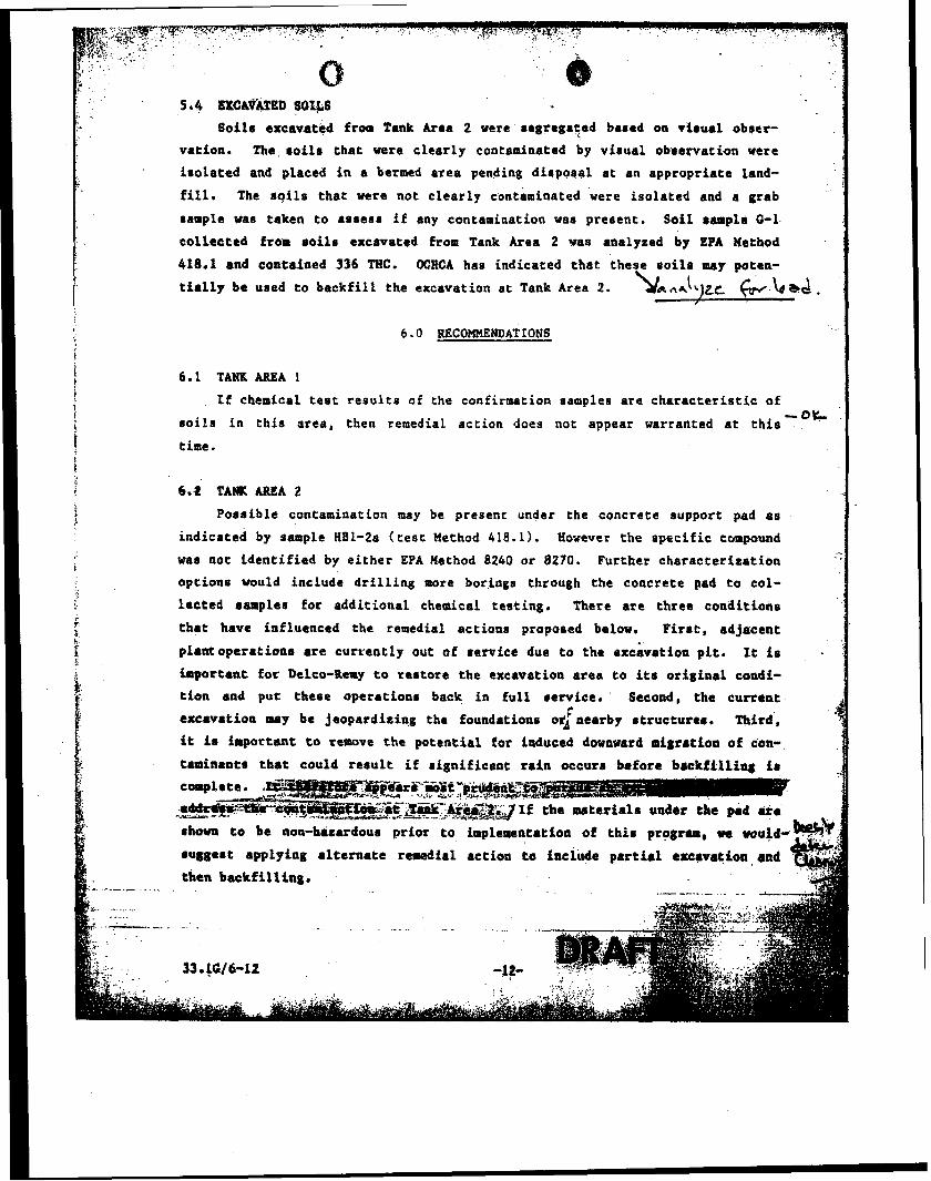
5.4 EXCAVATED SOI~LS Soilr excavated from Tank Area 2 vere segregated based on visual obser-
vation. The roilr that were clearly contaminated by virual obeervation vere j
irolated and placed in a bermed area pending dirrpoeal at an appropriate land- , !*
fill. The soils that vere not clearly contaminated were isolated and a grab
I sample vas taken to assess if any contamiaation was present. Soil $ample 0-1 I collected from roils escavatcd from Tank Area 2 was analyzed by EPA nethod I 418.1 and contained 336 THC. OCHCA has indicated chat these soil8 may poten-
tially be used to backfill the excavation at Tank Area 2. L f i n ~ k ) ~ ~ & b*d I 6 .0 RECOMMENDATIONS
6.1 TANK AREA 1
f If chemical test results of the confirmation samples are characteristic of I - 0 L
soils in this area, then remedial action does not appear warranted at this
time.
C 6.2 TANK AREA 2 I
Possible contamination may be present under the concrete support pad as
indicated by sample 881-2a (test Method 4 1 8 . 1 ) . However the specific compound
war not identified by either EPA Method 8240 or 8270. Further characterization
options would include drilling more borings through the concrete pad to c01-
lected samples for additional chemical testing. There are three conditions
that have influenced the remedial action8 proposed below. First, adjacent
plant operatioar are currently out of rervice due to the exc;vation pit. It is
hportaat for Delco-Remy to restore the excavation area to ita original condi-
tion and put there operations back in full eekvice. ' Second, the current L
excavation may be jeopardizing the foundatioas ot' nearby r tructurer . Third,
it is important to remove the potential for induced dovnvard migration of con-.
taminanta that could rerult if significant rain occurs before backfilling ir
e b o m to be non-bitordour prior to impleaentation of thir program, uc wuid-
rugsere applying alternate remedial action to inc1Ne partial erc.v.tioa, and
then backfilling.
. - . . . . -. ..

L _
'6 m e program recq~eaded to addreqs tlfe co'krnination in Tank Area 2 will
btt phaatd aa follovs:
The iaside of the excavation pit will be claared of vLually coatemi-
nated materials. These materials wi 11 be removed with a backhoe or
cranr. The material vill be -hemicallp tested as appropriate and w i ! l
be stockpiled above-ground with earlier excavated material for trans-
port offsite to an appropriate disposal site.
* After removal of visually contaminated soils, the concrete pad rill be
saw cut into ?arc.e blocks and removed from the excava~ion pit. The
removed concrete will be cleaned, visually inspected and chemically
1 testad. The concrete will be diepoeed of at an apptopriste aitt, recy-
cled for use in the production of concrete or used as backfill material
if it is suitable based on its chemical and pkyt~iccrl conditionr. i The roils underneath the concrete pad will then be excavaFed with a
- 4 ... crane to a maximum iielth OE 25 b e t bgs until such time aa visual ri-
dencc for contamlnatioo is not present in the excavation pit.' . . . ."b. ... 9.
Excavation activities will be vitnessed by representatives from Dames & Moore,
Delco-Remy, and Orange County Health Care Agency. ConfirmatSon sampling will
Upon removal sf contaminated soils from the excavation pit, the pit will be
r only be conducted if visual verification of contamination ie not p o s ~ i l 1 e . c ~ ~
C:
backfilled with clean fill material and recompacted to optimum density of . S O X .
Since ground vater i s present 30 feet bgs in the pit area. excavation activi-
ties vill not exceed 25 bgs.
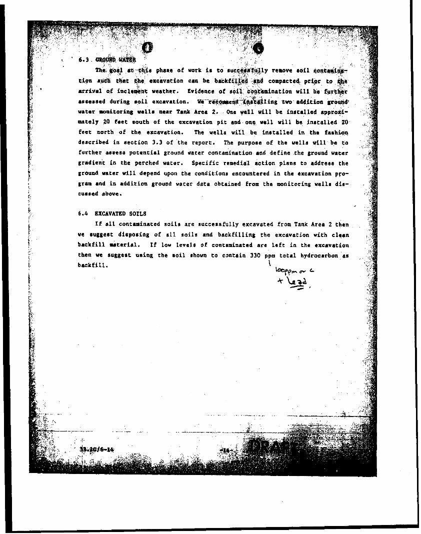
gradient in the perched vater. Specific remedial action plane to address the
k ground water will depend upon the conditions encountered in the excavation pro- f '
gram and in addition ground water data obtained from the monitoring velle dir - 1
cussed above. !
5 -
6.4 EXCAVATED SOILS
If a11 contaminated soils are successfully excavated from Tank Area 2 then t ve suggest dispoeing of all soils and backfilling the excavation w i t h c l e ~ n t . t backfill faaterial. If low levels of contaminated are left in the excavatien
backfill.
1. !. C -
U . '
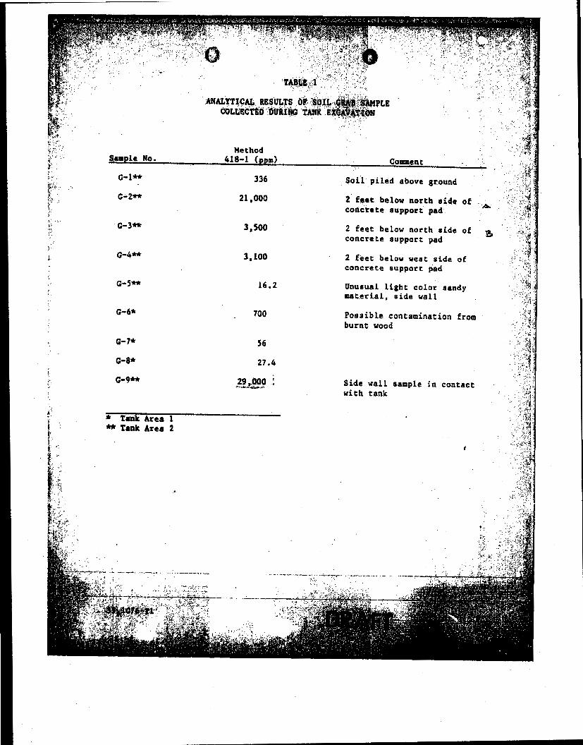
f * H e thod . -3 "-%
Y? 2 SaapLe No. 418-1. (ppm) Corm~cn t 8
:, C-I** 336 Soil piled above ground 3 f , ' 'F2
f- C-2** 21,000 2 feet below north aide of , * , +
codcrete eupport pad 1 --fl. 8
* T-k Area 1 Tank Area 2
2 feet below north side of ^- L
=I
concrete support pad 3 @ "C
:$ 2 feet below wert side of concrete support pad
Unusual Light color sandy material, side wall
4 .' Possible contamination from k * .: burnt vood ' ?
' $.
Side wall sample in contact L '
with tank ,.c?

TABLE 2
ANALYTICAL RESULTS OF UNDISTURBED SOIL SAYPLES COLLECTED IN ANGLE, HAND AUGER AND MONITORING WELL BORINGS
i-
i i
Adjusted 5 Adjusted
Depth Below Depth Belw He thod Sample No. Ground Surface Concrete Slab 418 (ppm)
1 81-1A 16 4 (at edge of C
2 1
5 slab)
2 31-2A 20 8 i N A . i I
HBI -2A
182-1 A*
2 . 5 ( a t edge af 10 excavation)
1 NA
10 N A
8400
ND (Method 8015 . , m (Method 8040
RD Rot detected
. - . . -- .... ... - . -_ . __ _ ._


GROUND 8URFACE
EX PLANAT ION:
m 8OIL $AMPLE LOCATION
E OROSND WATER

I Mr. Dave Hornizk Delco Remy
1 1201 N. Magnolia Anaheim, CA 92801
5 Dear Mr. Horniak:
il: Enclosed, p l e a s e f i n d c o p i e s o f m a n i f u t s f o r haza rdous was t e s removed f rom t h e D e l c o Remy f a c i l i t y i n J u l y , 1 9 8 6 . T h i s m a t e r i a l was g e n e r a t e d d u r i n g a n u n d e r g r o u n d t a n k r e m o v a l p r o j e c t . Fol lowing is a b r i e f d e s c r i p t i o n o f t h e s e w a s t e s and t h e i r d i s p o s a l sites:
Waste m a t e r R insea t e From Tank Cleaning
D i s o s a l S i t e b Z & G T G G n Compton, C A
84677276 12,000 Gallon Waste O i l Tank CWHI That Was Crushed On-Site Ket t leman Hills. CA
84674840 12,000 Gallon Waste Oil Tank C W M I Tha t was Shipped I n t a c t Ket t leman H i l l s . CA . --
If you have a d d i t i o n a l q u e s t i o n s , p l e a s e f e e l free t o c o n t a c t me a t (714) 983-0342.
Sincerely,
&&57 Rick Lambert Projeot Manager

FINAL REPORT SOILS INVESTIGATION FOR DELCO-REMY 120 1 N. MAGNOLIA ANAHEIM, CALIFORNIA - - .
JOB NO. 14397-002-042 - July 20, 1987 ..
.. ,:, . .. d
. . : .

- DAMES . . + & MOORE . . , n s q q b , rlullar mmlnwtnr - ' ~ O L L .BUSINESS CTR.. ,541 PARKWAY LOOP, STE. B. TU'S~IN. CALIF. 92680 (711) 259.9101
July 20, 1987
Delco-Remy 120 1 N . Magnolia Ave. Anaheim, G A 92803
A t t e n t i o n : MF. David Hornyak
Gentlemen:
P r e s e n t e d h e r e i n a r e t h e r e s u l t s o f o u r s o i l s a m p l i n g program conduc ted f o l l o w i n g t a n k removal a t 1201 N . Magnolia, Anaheim, C a l i f o r n i a .
It h a s been a p l e a s u r e working w i t h Delco-Remy on t h i s p r o j e c t . We l o o k f o r w a r d t o b e i n g o f c o n t . i n i t e d s e r v i c e t o you.
Very t r u l y y o u r s ,
DAMES & MOORE A qROFESS1ONAL LTD. PARTNERSHIP
~ n t h o n f S., Nelson I
P r o j e c t .Manage<,
William E. Halbert G e o l o g i s t

Ju ly 20, 1987 I 1 1
Delco-Remy 1201 N. Magnolia Anaheim, CA 92803
D I . - A t t en t ion : Mr. Dave Hornyak
Gentlemen:
F i n a l Report S o i l Sampling - Tank Area 2 1201 N. Magnolia ,
Anaheim, C a l i f o r n i a
I N T R O D U C T I O N
In t h i s l e t t e r r e p o r t we presen t t h e r e s u l t s and methods - o f a remediat ion program conducted a t . t he Deloo-Remy Ba t t e ry P l a n t , l o c a t e d i n Anaheim, C a l i f o r n i a . ( F i g u r e 1 ) . The
-. program was undertaken fo l lowing t h e d i saove ry of s o i l aontam- i n a t i o n du r ing t h e removal of two junderground s t o r a g e t a n k s
- which conta ined waste o i l .
Borings were d r i l l e d p- ior t o t h e remedia t ion program and r I : a r e o u t l i n e d i n t h e Si te C h a r a c t e r i z a t i o n and Remedial Action I
. -- Plan submi t ted by Damea & Moore November 4, 1986. I n short , 5
. . b o r i n g s were d r i l l e d and s o i l s a m p l e s taken t o assess t h e ;. 'a
e x t e n t of contaminat ion. One boring (MU-1) was developed as a p; - g r o u n d w a t e r m o n i t o r i n g w e l l ( F i g u r e 3). A n a l y s e s r u n on'
s e l e c t e d s o i l samples i n d i o a t e d hydrocarbon contamlnat lon waa p r e s e n t to a d e p t h two f e e t below-. t h e t a n k s ' a u p p o r t i n & , ' If--, oonore t e s l a b . The bo r ings d i d no t reveal, however, e%teqsi;v@

1
F r i z e C o r p o r a t i o n of I n d u s t r y , C a l i f o r n i a oonducted the e x c a v a t i o n u n d e r c o n t r a c t w i t h Delco-Remy. Dames & Moore ,
provided c o n s t r u c t i o n m o n i t o r i n g s e r v i c e s f o r Delco-Remy d u r i n g t h e c o u r s e o f e x c a v a t i o n .
I I
li I METHOD OF SAMPLING 1
i Grab samples o f s o i l were t a k e n f rom t h e bucket o f baok-
11 hoe f o r s u b m i t t a l t o Chemical Research L a b o r a t o r y (CRL) l o c a t e d j
I i n S t a n t o n , Ca. , !
i Fol lowing removal o f s loughed d e b r i s from t h e f l o o r of I
t h e e x c a v a t i o n , a b u a k e t f u l l o f s o i l was t a k e n f r o m t h e '
was brought t o t h e s u r f a c e , hydrocarbon vapor Pead ings were i t a k e n u s i n g a p o r t a b l e TLV s n i f f e r . P r i o r t o s a m p l i n g , t h e 1 upper s i x i n c h e s of s o i l was s c r a p e d away from t h e bucket . The sample was t h e n t a k e n from the u n d e r l y i n g s a i l u s i n g a c l e a n , s t a i n l e s s s teel scoop. The s o i l was plaoed i n a c l e a n , wide- mouth, g l a s s j-ar, and packed f i r m l y t o r e d u c e headspace. A T e f l o n s h e e t was t h e n p l a c e d o v e r t h e mouth o f t h e j a r and t h e l i d screwed on t i g h t l y . The l i d was t h e n s e a l e d u s i n g v iny l t a p e . L a b e l s were a f f i x e d t o t h e l i d o f e a c h a a m p l e a n d c o n t a i n e d t h e f o l l o w i n g i n f o r m a t i o n : 1) sample number; 2) d a t e ; 3) d e p t h ; 4 ) c o l l e c t o r s i n i t i a l s ; 5 ) owner; 6) loeation; and 7) t ime . Appropr ia te ly , s e a l e d and l a b e l e d s a m p l e s were stored i n c o o l e r s w i t h ice. The s a m p l e s were t h e n t r a n s f e r r e d
o f c u s t o d y forms are i n c l u d e d i n Appendix 3.

0 Q wlco-Remy ~ u l y 20, 1987 Page 3
CHRONOLOGICAL SUMMARY
Following t ank removal and i n i t i a l s o i l sampling, a s i t e I
c h a r a c t e r i z a t i o n p l a n was p r e p a r e d and s u b m i t t e d t o Orange i I
County f o r review and concur rence . Subsequent ly t h e charaa- 1
t e r i z a t i o n s t u d y bas conducted t o a s s e s s t h e e x t e n t o f contam- !
i n a t i o n . P r i o r t o e x c a v a t i o n , c leanup l e v e l s were s e t at 100 ppm TPHC by Ms. Debb ie Greco o f Orange County H e a l t h Care Agency (OCHCA). T h e r e a f t e r , a program was begun by Deloo-Remy t o excava t e contaminated so118 i n t h e v i c i n i t y of' Tank Area I . 1 1 F r i z e Corpora t ion was r e t a i n e d by Delco-Remy t o conduct t h e 1 s h o r i n g and excava t ion . S o i l s removed du r ing t h e program were s t o c k p i l e d o n s i t e f o r subsequent t r ea tmen t and/or d i s p o s a l . Dames & Hoore p e r i o d i a a l l y c o l l e c t e d s o i l s amples f rom t h e
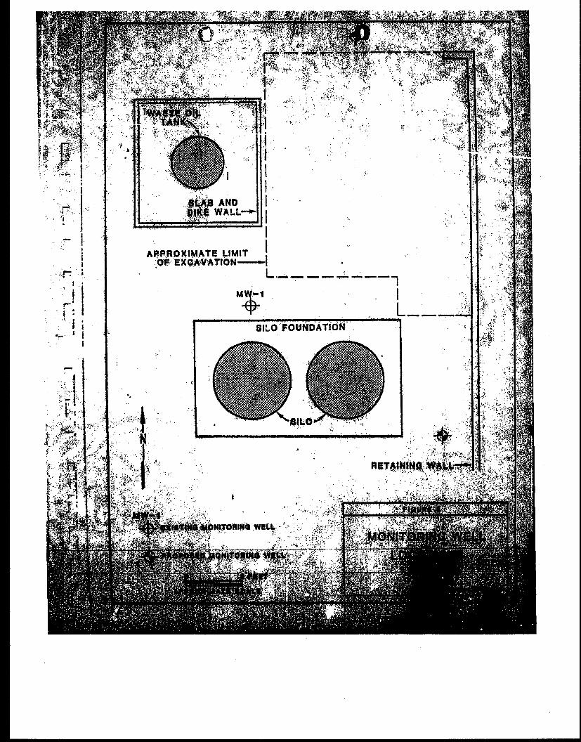
p i t s i d e w a l l s and p i t bottom (F igu re 2 ) . . I
The s o u t h and west walls of t h e p i t were shored t o prevent c a v i n g and t o , a s a i s t i n s u p p o r t i n g s o i l s b e n e a t h two s i l o s immediately t o t h e sou th of t h e ' excava t ion a r e a . A r e t a i n i n g w a l l ( a l r e a d y e x i s t i n g ) provided suppor t f o r s o i l s t o t h e east of t h e excava t ion . It was dec lded j o i n t l y by Delco, F r i z e and Danes & Moore t h a t removal o f t h e contaminated s o i l s would b e s t be achieved by d i v i d i n g t h e exoava t ion i n t o t h r e e s e a t i o n s , ' r auh a e o t i o n r u n n i n ~ eas t -wes t , and removing t h e contaminated s o i l from each s e c t i o n i n d i v i d u a l l y , Contaminated s o i l a were s t o c k p i l e d i n a bermed a r e a o n s i t e p r i o r t o d i s p o a a l a t an I.T. CorporaLion f a c i l i t y i n f m p e r i a l County, C a l i f o r n i a .

o u t from east t o wes t and t h e c o n o r e t e removed o v e r t h e area to b e e x c a v a t e d . The s o i l was removed t o a d e p t h o f 2 1 f ee t below ground s u r f a c e ( b g s ) and 6 samples were t a k e n t o assess t h e l e v e l s o f con tamina t ion p r e s e n t (samples SP1-6). A f u r t h e r sample was t a k e n ;at 23 f e e t (SP7) t o a s s e s s i f f u r t h e r exoa- v a t i o n was n e c e s s a r y . T h e f o l l o w i n g d a y (12 -16-86) t h e
v e r b a l r e s u l t s of a n a l y s e s were r e p o r t e d t o Ms. Debby Greco of Orange County H e a l t h Care Agency (OCHCA). A t t h a t time s h e ' gave h e r v e r b a l o o n s e n t f o r b a c k f i l l i n g and oompaotion o f t h e n o r t h e r n t h i r d , pendina w r i t t e n r e s u l t s ot' t h e a n a l y s e s from CRL.
On 12-17-86 t h e n o r t h e r n t h i r d o f t h e e x c a v a t i o n was b a c k f i l l e d t o a d e p t h o f 24 f e e t bgs and compacted t o a t least 90% b u l k d r y d e n s i t y . The n o r t h e r n a r e a was t h e n f u r t h e r ramped t o g a i n a c c e s s t o t h e s o u t h e r n p o r t i o n o f t h e excava- t i o n .
On 12-21-86 t h e n o r t h e r n s i l o immediate ly s o u t h o f t h e e x c a r a t i o n was mov-d t o t h e west o f t h e s o u t h e r n s i l o . T h i s move was n e c e s s a r y t o p r e v e n t e t r u a t u r a l f a i l u r e s h o u l d s lough- i n g of t h e s o u t h e r n w a l l o c c u r d u r i n g c o n t i n u e d s o i l ramoval ( F i g u r e 2).
I On F r i d a y , 12-26-86, s h o r i n g was removed from t h e s o u t h I
and west walls o f t he e x c a v a t i o n a n d t h e r e m a i n i n g p o r t i a n o f t h e c o n c r e t e was broken u s i n g a h y d r a u l i a b r e a k e r oq t h e end o f
I t h e l o a d e r arm. The c o n c r e t e and- re -bar was t h e n l o a d e d Lnto a n end dump t r u o k and t r a a a ' p o r t e d t o the a t o o k p i l e area ons.ite.

E x c a v a t i o n o f t h e s o u t h e r n w a l l was h i n d e r e d by t h e presence of a bur ied 10' f i r e p ro t ec t ion supply l i n e whioh ran a e r o s s t h e s o u t h e r n p o r t i o n of t h e excs iva t ion . Aa F r i z e Corporat ion uncovered t h e l i n e , i t was supporcted with cha ins suspended from a 2 4 inch h i g h I-beam running from t h e r e t a i n i n g
e
z wal l on t h e e a s t t o undisturbed s o i l s ;n t h e west. Care was i - ! t aken not t o h i t t h e l i n e with t h o backhoe bucket, There was '
a l s o concern f o r s o i l s t a b i l i t y beneath t h e southern s i l o wi th ; I I
i I con t inued excavat ion t o t h e south . It was decided by Delco- Remy t h a t excavat ion would s t o p 3' ( O W bucket u i d t h ) sou th 0s i
I !! t h e f i r e l i n e whereupon s ide wall samples would be taken Lo , - a s s e s s r e m a i n i n g c o n t a m i n a t i o n l e v e l s . V i s u a l e v i d e n c e o f 1
c o n t a m i n a t i o n was l i m i t e d t o two o r t h r e e l e n t i c u l a r a r e a s
a r e a s were exposed f o l l o w i n g t h e removal of' t h e s h o r i n g .
i a t o r near t h e e l e v a t i o n of t h e former conc re t e s l a b . These i
These s o i l s were excavated and not ev iden t a t r poin t 3' s o u t h 1 of' t h e f i r e p r o t e c t i o n l i n e . Samples were c o l l e o t e d a t two. :' I l o a a t l o n a shown i n F igure 2. M r David G i f f o r d , S a n i t a r i a n , o f ' , '
Orange County Health Care Agency (3CHCA) was present du r ing I o o l l e r i t i o n of t h e s e s a m p l e s and d i r e c t e d t h e c o n f l r m a t l o n I I( sample l o o a t ions .
- Free o i l was no t i ced on t h e Sooting of t h e r e t a i n i n g wall border ing t h e e a s t e r n s i d e of t h e excavat ion . The o i l was very
- ( t h l c k , a lmost t a r - l i k e , and t h e l a t e r a l e x t e n t seemed t o end 6 1 i ! + 1 t o 8 f e e t s o u t h o f t h e f i r e y r o t e c t l o n l i n e . T h i s oil was I I! 11 r emoved f r o m t h e f o o t i n g p r i o r t o b a o k f i l l l n g of t h e I : . -
I excavat ion .
Reaoval of s o i l s from beneath t h e oonore te 81.6 In . t h . I 1
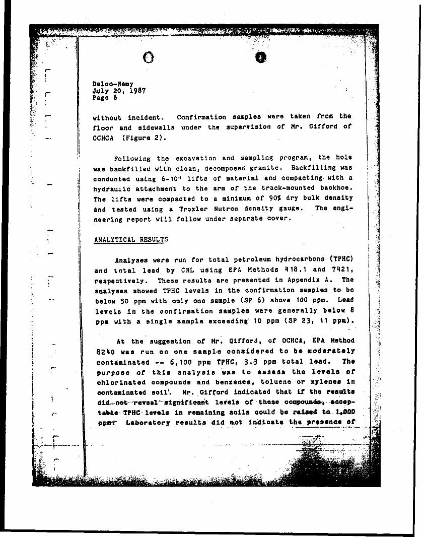
w i t h o u t i n c i d e n t . C o n f i r m a t i o n s a m p l e s were t a k e n from t h e f l o o r and s i d e w a l l s under t h e s u p e r v i s i o n of Mr. Giff'ord o f OCHCA ( F i g u r e 2 ) .
I' Fo l lowing t h e e x c a v a t i o n and sampi log program, t h e h o l e I
I was b a c k f i l l e d w i t h c l e a n , decomposed g r a n i t e , B a c k f i l l i n g was i ! I oonduc ted u s i n g 6-10" l i f ts of m a t e r i a l and compac t ing w i t h a I il
h y d r a u i i c a t t a c h m e n t t o t h e am of' t h e traak-mounted baokhoe. i 'I The l i f t s were compacted t o a minimum of' 90% d r y b u l k d e n s i t y I !j and t e s t e d v a i n 8 a T r o x l e r Nutron d e n s i t y gauge. The s n g i -
1 n e e r i n g r e p o r t w i l l f o l l o w under s e p a r a t e c o v e r . ;I I1
' ANALYTICAL RESULTS i !
Analyses were r u n f o r t o t a l p e t r o l e u m hydrocarbons (TPHC) i '
a n d t o t a l l e a d by CRL u s i n g EPA Methods 418.1 and 7421, r e s p e c t i v e l y . These r e s u l t s a r e p r e s e n t e d i n Appendix A . The a n a l y s e s showed TPHC l e v e l s i n t h e c o n f i r m a t i o n samples t o b e 1 below SO ppm w i t h o n l y o n e sample (SP 6 ) above 100 ppm. Lead li
l e v e l s i n t h e c o n f i r m a t i o n samples were g e n e r a l l y b e l o w 8 9 ppm with a s i n g l e s a m p l e e x c e e d i n g ' 10 ppm (SP 23, 11 ppm). ..i
< T
8 2 4 0 was r u n o n o n e samp1.e e o n s i d e r e d t o b e moderately c o n t r m f n a t e d -- 6,100 ppm TPHC, 3 . .3 ppm t o t a l lead. Tbe
, . . . .

Pelco-Remy J u l y 20 , 1987 Page 7
c h l o r i n a t e d compounds nor benzenes o r x y l e n e s . Toluene was d e t e c t e d , however,. a t 0.08 ppm s l i g h t l y above i t s d e t e c t i o n l i m i t .
I n genera;, S o i l c c n t a m i n a t i o n w i t h pe t ro leum hydrooarbons and l e a d was removed i n Tank Area 2 . Leve l s o f TPHC and t o t a l l e a d i n t h e r e m a i n i n g s o i l s a p p e a r t o be b e l o w O C H C A
recommended a c t i o n l e v e l s . For s a i l s t h a t may h a v e TPHC c o n t a m i n a t i o n a b o v e 100 pprn, a d d i t i o n a l t e s t i n g showed n o c h l o r i n a t e d compounds nor t h e p resence o f benzenes o r x y l e n e s .
r MONITORING WELLS
il Fol lowing t h e i n s t a l l a t i o n and development o f m o n i t o r i n g
well MW-1 n e a r t h e southwest c o r n e r of t h e e x c a v a t i o n , water samples were c o l l e o t c d and ana lyzed . The w a t e r c o l l e c t e d was a c l o u d y brown c o l o r and had a pH of 9.0 t o 9:6 . T e s t r e s u l t s from EPA Methods 601 ( V o l a t i l e Hydrocarbons) , '625 (Base/NButra l E x t r a c t a b l e ) and 418 .1 (TPHC) d i d n o t d e t e c t any c o n t a m i n a t i o n .
'T
I" N o n e t h e l e s s , t h e ground wate r a p p e a r s t o e x h i b i t a pH t h a t ! i s i n c o n s l s t a n t w i t h t h a t of n a t u r a l w a t e r and a p p e a r . t o
. - ' h a v e . been modi f i ed . 1.- As s t a t e d i n S i t e C h a r a c t e r i z a t i o n and Remedial Aotion
Plan , two a d d i t i o n a l ground-water moni to r ing w e l l s are proposed t o b e i n s t a l l e d a d j a o e n t t o Tank Area 2 ( F i g u r e 3 ) . The p u r p o s e of' t h e s e lwells w i l l , be t o f u r t h e r assess groundwa%er a o n t a m i n a t i o n and d e f i n e t h e g r a d i e n t o f t h e 7
r 1 3 p i c i f i c r d m e d i a l a o t i o n p l a n 8 t a addre.. t h e &round w a t e r w i l l I '.'
d e p e n d u p o n t h e g r o u n d water d a t a o b t a i n e d * , .
. . . ..-.oao~m,, .. . .- -.-
Thank you for t h e opportunity t o perform t h i s s o i l sam- p l i n g program f o r Delco-Remy. We look forward t o b e i n g o f continued service to you.
I 1 Very truly yours, I DAMES & MOORE I
A PROFESSIONAL LTD. PARTNERSHIP j
~ n t h o n y ~ . Nelson . I Project Manager Registered. Gaologi2t 44 175 I
- I 4 I
William E. Halbert Geologist !
I I

APPROXIMATE LIMIT 8 I,,+? OF ~ X C A V A T I O N ~ '
I 8 P I O
! A( 1 3')