dell storage centertopics-cdn.dell.com/pdf/storage-sc180_owner's manual_en-us.pdf ·...
TRANSCRIPT

Dell Storage CenterSC180 Expansion Enclosure
Owner's Manual
Regulatory Model: E11JRegulatory Type: E11J001

Notes, Cautions, and WarningsNOTE: A NOTE indicates important information that helps you make better use of your computer.
CAUTION: A CAUTION indicates either potential damage to hardware or loss of data and tells you how to avoid the problem.
WARNING: A WARNING indicates a potential for property damage, personal injury, or death.
© 2016 Dell Inc. All rights reserved. This product is protected by U.S. and international copyright and intellectual property laws. Dell and the Dell logo are trademarks of Dell Inc. in the United States and/or other jurisdictions. All other marks and names mentioned herein may be trademarks of their respective companies.
2016 - 06
Rev. A01
Contents
About this Guide.......................................................................................................5Revision History..................................................................................................................................... 5
Audience................................................................................................................................................ 5
Contacting Dell......................................................................................................................................5
Related Publications.............................................................................................................................. 5
1 About the SC180 Expansion Enclosure.............................................................7SC180 Expansion Enclosure Overview................................................................................................. 7
SC180 Expansion Enclosure Monitoring and Diagnostics...................................................................7
SC180 Expansion Enclosure Front-Panel Features and Indicators..................................................... 7
SC180 Expansion Enclosure Back-Panel Features and Indicators......................................................9
SC180 Expansion Enclosure EMM Features and Indicators.........................................................10
SC180 Expansion Enclosure Cooling Fan Module Features and Indicators................................11
SC180 Expansion Enclosure PSU Features and Indicators.......................................................... 12
SC180 Expansion Enclosure Drive Numbering.................................................................................. 13
SC180 Expansion Enclosure Drives.................................................................................................... 13
2 Replacing SC180 Expansion Enclosure Components..................................15Safety Precautions............................................................................................................................... 15
Installation Safety Precautions...................................................................................................... 15
Electrical Safety Precautions......................................................................................................... 16
Electrostatic Discharge Precautions............................................................................................. 16
General Safety Precautions........................................................................................................... 16
Pre-Replacement Procedures.............................................................................................................17
Send Diagnostic Data Using Dell SupportAssist........................................................................... 17
Put the Storage Center Into Maintenance Mode..........................................................................17
Shut Down the Storage System.....................................................................................................17
Replacing PSUs....................................................................................................................................18
Identifying the Failed PSU..............................................................................................................18
Replacing a PSU ............................................................................................................................19
Replacing Cooling Fan Modules......................................................................................................... 21
Identifying the Failed Cooling Fan Module...................................................................................21
Replacing a Cooling Fan Module..................................................................................................22
Replacing Hard Drives.........................................................................................................................24
Identifying the Failed Hard Drive.................................................................................................. 24
Replacing a Hard Drive..................................................................................................................25
Replacing an Enclosure Management Module..................................................................................30
Identifying the Failed Enclosure Management Module...............................................................30
Replacing an Enclosure Management Module.............................................................................31
3
Replacing Rack Rails............................................................................................................................32
Post-Replacement Procedures.......................................................................................................... 33
Start Up the Storage System and Expansion Enclosure...............................................................33
Send Diagnostic Data Using Dell SupportAssist...........................................................................33
3 Troubleshooting SC180 Components............................................................34Troubleshooting Cooling Fan Modules............................................................................................. 34
Troubleshooting PSUs........................................................................................................................ 34
Troubleshooting Hard Drives............................................................................................................. 34
Troubleshooting EMMs.......................................................................................................................35
4 SC180 Expansion Enclosure Technical Specifications................................36Technical Specifications..................................................................................................................... 36
4

Preface
About this GuideThis guide describes how to perform service and maintenance on the SC180 expansion enclosure.
Revision History
Document Number: MV429
Revision Date Description
A00 March 2015 Initial release
A01 June 2016 Updated pre-replacement procedures and clarified requirements
AudienceThe information provided in this guide is intended for use by Dell end users.
Contacting DellDell provides several online and telephone-based support and service options. Availability varies by country and product, and some services might not be available in your area.
To contact Dell for sales, technical support, or customer service issues, go to www.dell.com/support.
• For customized support, type your system service tag on the support page and click Submit.
• For general support, browse the product list on the support page and select your product.
Related PublicationsThe following documentation is available for the SC180 expansion enclosure.
• Dell Storage Center SC180 Expansion Enclosure Getting Started Guide
Provides information about an SC180 expansion enclosure, such as installation instructions and technical specifications.
• Dell Storage Center Release Notes
Provides information about new features and known and resolved issues for the Storage Center software.
• Dell Storage Center Update Utility Administrator’s Guide
Describes how to use the Storage Center Update Utility to install Storage Center software updates. Updating Storage Center software using the Storage Center Update Utility is intended for use only by sites that cannot update Storage Center using standard methods.
• Dell Storage Center Software Update Guide
Describes how to update Storage Center software from an earlier version to the current version.
• Dell Storage Center Command Utility Reference Guide
5

Provides instructions for using the Storage Center Command Utility. The Command Utility provides a command-line interface (CLI) to enable management of Storage Center functionality on Windows, Linux, Solaris, and AIX platforms.
• Dell Storage Center Command Set for Windows PowerShell
Provides instructions for getting started with Windows PowerShell cmdlets and scripting objects that interact with the Storage Center using the PowerShell interactive shell, scripts, and PowerShell hosting applications. Help for individual cmdlets is available online.
• Dell Storage Manager Client Administrator’s Guide
Provides information about the Dell Storage Manager Client and how it can be used to manage a Storage Center.
• Dell Storage Manager Administrator’s Guide
Provides instructions for using the Data Collector Manager and the Dell Storage Manager Client.
• Dell TechCenter
Provides technical white papers, best practice guides, and frequently asked questions about Dell Storage products. Go to http://en.community.dell.com/techcenter/storage/.
6
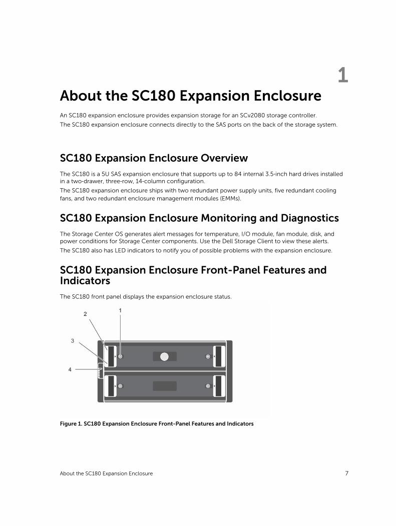
1About the SC180 Expansion EnclosureAn SC180 expansion enclosure provides expansion storage for an SCv2080 storage controller.
The SC180 expansion enclosure connects directly to the SAS ports on the back of the storage system.
SC180 Expansion Enclosure OverviewThe SC180 is a 5U SAS expansion enclosure that supports up to 84 internal 3.5‐inch hard drives installed in a two‐drawer, three‐row, 14‐column configuration.
The SC180 expansion enclosure ships with two redundant power supply units, five redundant cooling fans, and two redundant enclosure management modules (EMMs).
SC180 Expansion Enclosure Monitoring and DiagnosticsThe Storage Center OS generates alert messages for temperature, I/O module, fan module, disk, and power conditions for Storage Center components. Use the Dell Storage Client to view these alerts.
The SC180 also has LED indicators to notify you of possible problems with the expansion enclosure.
SC180 Expansion Enclosure Front-Panel Features and IndicatorsThe SC180 front panel displays the expansion enclosure status.
Figure 1. SC180 Expansion Enclosure Front-Panel Features and Indicators
About the SC180 Expansion Enclosure 7
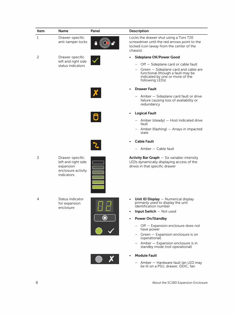
Item Name Panel Description
1 Drawer-specific anti-tamper locks
Locks the drawer shut using a Torx T20 screwdriver until the red arrows point to the locked icon (away from the center of the chassis).
2 Drawer-specific left and right side status indicators
• Sideplane OK/Power Good
– Off — Sideplane card or cable fault
– Green — Sideplane card and cable are functional (though a fault may be indicated by one or more of the following LEDs)
• Drawer Fault
– Amber — Sideplane card fault or drive failure causing loss of availability or redundancy
• Logical Fault
– Amber (steady) — Host indicated drive fault
– Amber (flashing) — Arrays in impacted state
• Cable Fault
– Amber — Cable fault
3 Drawer-specific left and right side expansion enclosure activity indicators
Activity Bar Graph — Six variable-intensity LEDs dynamically displaying access of the drives in that specific drawer
4 Status indicator for expansion enclosure
• Unit ID Display — Numerical display primarily used to display the unit identification number
• Input Switch — Not used
• Power On/Standby
– Off — Expansion enclosure does not have power
– Green — Expansion enclosure is on (operational)
– Amber — Expansion enclosure is in standby mode (not operational)
• Module Fault
– Amber — Hardware fault (an LED may be lit on a PSU, drawer, DDIC, fan
8 About the SC180 Expansion Enclosure
Item Name Panel Description
module, or IO module indicating the part at fault)
• Logical Status:
– Amber — Change of status or fault from something other than the storage system itself (this status is typically associated with a disk drive as indicated by its own fault LED)
• Drawer 1 Fault
– Amber — Drive, cable, or sideplane fault has occurred in drawer 1
• Drawer 2 Fault
– Amber — Drive, cable, or sideplane fault has occurred in drawer 2
NOTE: Both drawer fault LEDs (and all contained DDIC LEDs) will flash when the expansion enclosure indicator is set to On in Storage Client.
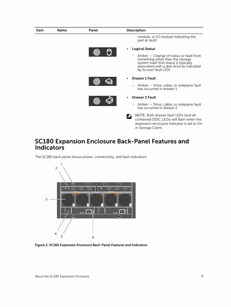
SC180 Expansion Enclosure Back-Panel Features and IndicatorsThe SC180 back panel shows power, connectivity, and fault indicators.
Figure 2. SC180 Expansion Enclosure Back-Panel Features and Indicators
About the SC180 Expansion Enclosure 9

Item Name Icon Description
1 Optional cable retention positions (4)
— Locations for optional cable retention brackets.
2 Expansion Enclosure Modules (2)
— Each EMM contains SAS ports and status indicators.
3 Cooling fans (5) — Fans that provide cooling for the expansion enclosure.
4 Power supply units (2)
— 2.8 kW power supply that provides power for the expansion enclosure.
5 Optional cable retention positions (4)
— Locations for optional cable retention brackets.
6 Power switch (2) — Controls power for the expansion enclosure. There is one switch for each power supply.
SC180 Expansion Enclosure EMM Features and Indicators
An SC180 includes two enclosure management modules (EMMs) in two Storage Bridge Bay (SBB) interface slots.
Figure 3. SC180 Expansion Enclosure EMM Features and Indicators
Item Control/Feature
Icon Description
1 Fault LED • Off — Module OK
• Amber — Module fault
2 Power LED • Green (steady) — Module OK
• Green (flashing) — Vital product data (VPD) fault
• Off — Module fault
3 Console port — Not for customer use
4 SAS ports — Connects to a storage controller.
10 About the SC180 Expansion Enclosure
Item Control/Feature
Icon Description
5 SAS activity indicators
— There are four SAS PHYs per SAS port.
• Off: SAS PHY is not connected
• Steady green: SAS PHY is connected, but no activity
• Blinking green: SAS PHY is not connected plus activity
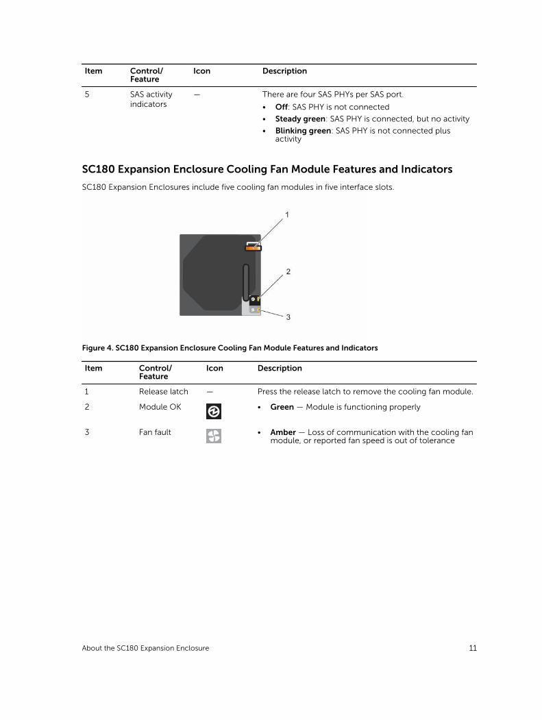
SC180 Expansion Enclosure Cooling Fan Module Features and Indicators
SC180 Expansion Enclosures include five cooling fan modules in five interface slots.
Figure 4. SC180 Expansion Enclosure Cooling Fan Module Features and Indicators
Item Control/Feature
Icon Description
1 Release latch — Press the release latch to remove the cooling fan module.
2 Module OK • Green — Module is functioning properly
3 Fan fault • Amber — Loss of communication with the cooling fan module, or reported fan speed is out of tolerance
About the SC180 Expansion Enclosure 11
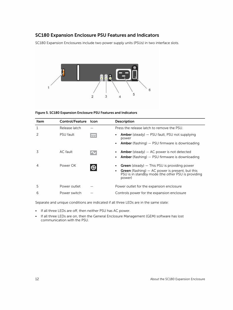
SC180 Expansion Enclosure PSU Features and Indicators
SC180 Expansion Enclosures include two power supply units (PSUs) in two interface slots.
Figure 5. SC180 Expansion Enclosure PSU Features and Indicators
Item Control/Feature Icon Description
1 Release latch — Press the release latch to remove the PSU.
2 PSU fault • Amber (steady) — PSU fault, PSU not supplying power
• Amber (flashing) — PSU firmware is downloading
3 AC fault • Amber (steady) — AC power is not detected
• Amber (flashing) — PSU firmware is downloading
4 Power OK • Green (steady) — This PSU is providing power
• Green (flashing) — AC power is present, but this PSU is in standby mode (the other PSU is providing power)
5 Power outlet — Power outlet for the expansion enclosure
6 Power switch — Controls power for the expansion enclosure
Separate and unique conditions are indicated if all three LEDs are in the same state:
• If all three LEDs are off, then neither PSU has AC power.
• If all three LEDs are on, then the General Enclosure Management (GEM) software has lost communication with the PSU.
12 About the SC180 Expansion Enclosure
SC180 Expansion Enclosure Drive NumberingIn the SC180 expansion enclosure, the drive slots are numbered 1–42 in the top drawer and 43–84 in the bottom drawer. Dell Storage Client identifies drives as XX-YY, where XX is the number of the unit ID of the expansion enclosure, and YY is the drive position inside the expansion enclosure.
Figure 6. SC180 Expansion Enclosure Drawers and Drive Numbering
1. Bottom drawer viewed from above 2. Top drawer viewed from above
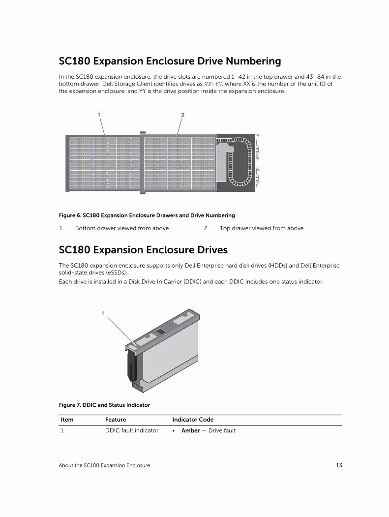
SC180 Expansion Enclosure DrivesThe SC180 expansion enclosure supports only Dell Enterprise hard disk drives (HDDs) and Dell Enterprise solid-state drives (eSSDs).
Each drive is installed in a Disk Drive In Carrier (DDIC) and each DDIC includes one status indicator.
Figure 7. DDIC and Status Indicator
Item Feature Indicator Code
1 DDIC fault indicator • Amber — Drive fault
About the SC180 Expansion Enclosure 13
Item Feature Indicator Code
• Amber (flashing) — Flashes in 1-second intervals when drive or enclosure indicator is set to On in Dell Storage Client.
With the drive indicator, the containing drawer fault LED will also flash. With the enclosure indicator, all drives’ and both drawers’ fault LEDs will flash.
14 About the SC180 Expansion Enclosure
2Replacing SC180 Expansion Enclosure ComponentsThis section describes how to remove and install components of the SC180 expansion enclosure.
This information assumes that you have received the replacement component and are ready to install it.
Safety PrecautionsAlways follow these safety precautions to avoid injury and damage to Storage Center equipment.
If equipment described in this section is used in a manner not specified by Dell, the protection provided by the equipment could be impaired. For your safety and protection, observe the rules described in the following sections.
NOTE: See the safety and regulatory information that shipped with each Storage Center component. Warranty information is included within this document or as a separate document.
Installation Safety Precautions
Follow these safety precautions:
• Dell recommends that only individuals with rack-mounting experience install the SC180 in a rack.
• You need at least two people to lift the expansion enclosure chassis from the shipping box and three people to install it in the rack. The empty chassis weighs approximately 62 kg (137 lbs).
• Make sure the expansion enclosure is always fully grounded to prevent damage from electrostatic discharge.
• When handling the expansion enclosure hardware, use an electrostatic wrist guard (not included) or a similar form of protection.
The chassis must be mounted in a rack. The following safety requirements must be considered when the chassis is being mounted:
• The rack construction must be capable of supporting the total weight of the installed chassis. The design should incorporate stabilizing features suitable to prevent the rack from tipping or being pushed over during installation or in normal use.
• When loading a rack with chassis, fill from the bottom up; empty from the top down.
• To avoid danger of the rack toppling over, slide only one chassis out of the rack at a time.
• The expansion enclosure must be operated with low-pressure rear exhaust installation (back pressure created by rack doors and obstacles not to exceed 5 Pascals [0.5 mm water gauge]).
Replacing SC180 Expansion Enclosure Components 15
Electrical Safety Precautions
Always follow electrical safety precautions to avoid injury and damage to Storage Center equipment.
WARNING: Disconnect power from the expansion enclosure when removing or installing components that are not hot-swappable. When disconnecting power, first power down the storage system using the Dell Storage Client and then unplug the power cords from the power supplies in the storage system and expansion enclosure.
• Provide a suitable power source with electrical overload protection. All Storage Center components must be grounded before applying power. Make sure that there is a safe electrical earth connection to power supply cords. Check the grounding before applying power.
• The plugs on the power supply cords are used as the main disconnect device. Make sure that the socket outlets are located near the equipment and are easily accessible.
• Know the locations of the equipment power switches and the room's emergency power-off switch, disconnection switch, or electrical outlet.
• Do not work alone when working with high-voltage components.
• Use rubber mats specifically designed as electrical insulators.
• Do not remove covers from the power supply unit. Disconnect the power connection before removing a power supply from the expansion enclosure.
• Do not remove a faulty power supply unless you have a replacement model of the correct type ready for insertion. A faulty power supply must be replaced with a fully operational module power supply within 24 hours.
• Unplug the expansion enclosure chassis before you move it or if you think it has become damaged in any way. When powered by multiple AC sources, disconnect all supply power for complete isolation.
Electrostatic Discharge Precautions
Always follow electrostatic discharge (ESD) precautions to avoid injury and damage to Storage Center equipment.
Electrostatic discharge (ESD) is generated by two objects with different electrical charges coming into contact with each other. The resulting electrical discharge can damage electronic components and printed circuit boards. Follow these guidelines to protect your equipment from ESD:
• Dell recommends that you always use a static mat and static strap while working on components in the interior of the expansion enclosure chassis.
• Observe all conventional ESD precautions when handling plug-in modules and components.
• Use a suitable ESD wrist or ankle strap.
• Avoid contact with backplane components and module connectors.
• Keep all components and printed circuit boards (PCBs) in their antistatic bags until ready for use.
General Safety Precautions
Always follow general safety precautions to avoid injury and damage to Storage Center equipment.
• Keep the area around the expansion enclosure chassis clean and free of clutter.
• Place any system components that have been removed away from the expansion enclosure chassis or on a table so that they are not in the way of foot traffic.
• While working on the expansion enclosure chassis, do not wear loose clothing such as neckties and unbuttoned shirt sleeves, which can come into contact with electrical circuits or be pulled into a cooling fan.
16 Replacing SC180 Expansion Enclosure Components
• Remove any jewelry or metal objects from your body because they are excellent metal conductors that can create short circuits and harm you if they come into contact with printed circuit boards or areas where power is present.
• Do not lift the expansion enclosure chassis by the handles of the power supply units (PSUs). They are not designed to hold the weight of the entire chassis, and the chassis cover may become bent.
• Before moving the expansion enclosure chassis, remove the PSUs to minimize weight.
• Do not remove drives until you are ready to replace them.
NOTE: To ensure proper expansion enclosure cooling, hard drive blanks must be installed in any hard drive slot that is not occupied.
Pre-Replacement ProceduresPerform the procedures described in this section before replacing a component of the SC180 expansion enclosure.
Send Diagnostic Data Using Dell SupportAssist
Use Dell SupportAssist to send diagnostic data to Dell Technical Support Services.
1. Use the Storage Client to connect to the Storage Center.
2. In the Summary tab, click Send SupportAssist Information Now, which is located under SupportAssist Actions in the Status pane. The Send SupportAssist Information Now dialog box opens.
3. Select Storage Center Configuration and Detailed Logs.
4. Click OK.
The Storage Client displays the status of the SupportAssist action. A second dialog box opens when the transfer of SupportAssist information has completed successfully.
5. Click OK.
Put the Storage Center Into Maintenance Mode
Use Dell Storage Client to put the Storage Center into maintenance mode after sending SupportAssist data to Dell Technical Support Services.
1. In the Summary tab, click Edit Settings. The Edit Storage Center Settings dialog box opens.
2. In the General tab, select Maintenance from the Operation Mode drop-down menu.
3. Click OK.
The Storage Center is put into maintenance mode.
Shut Down the Storage System
If the field replaceable unit (FRU) is not hot-swappable, use the Dell Storage Client to shut down the storage system. Shutting down the storage system results in a system outage, so plan to perform these procedures during a maintenance window.
PrerequisitesBefore shutting down the storage system, perform the following tasks:
1. Identify the failed part.
2. Identify the replacement part.
3. Make sure you have the tools required to replace the part.
Replacing SC180 Expansion Enclosure Components 17
Steps
1. In the Summary tab, select Actions → System → Shut Down/Restart. The Shut Down/Restart dialog box opens.
2. From the What should the Storage Center do? drop-down menu, select Shut Down.
3. Click OK.
When the storage system is shut down, unplug the power cables from the storage system and expansion enclosures.
Replacing PSUsThe SC180 expansion enclosure supports two hot-swappable power supply units (PSUs). If one unit fails, the second unit continues to provide power to the expansion enclosure.
Identifying the Failed PSU
To determine which power supply unit (PSU) failed, use the Dell Storage Client.
1. Click the Hardware tab.
2. In the Hardware tab navigation pane, select and expand the failed storage system.
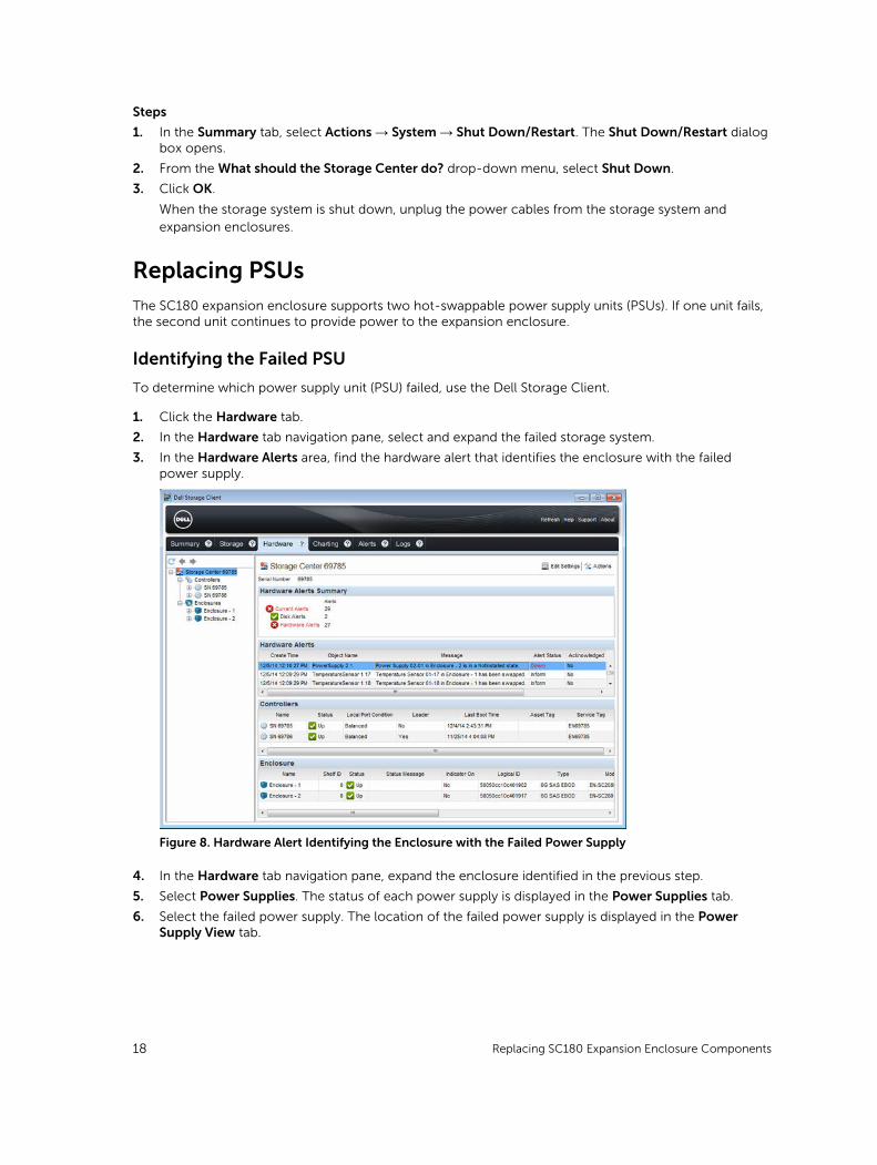
3. In the Hardware Alerts area, find the hardware alert that identifies the enclosure with the failed power supply.
Figure 8. Hardware Alert Identifying the Enclosure with the Failed Power Supply
4. In the Hardware tab navigation pane, expand the enclosure identified in the previous step.
5. Select Power Supplies. The status of each power supply is displayed in the Power Supplies tab.
6. Select the failed power supply. The location of the failed power supply is displayed in the Power Supply View tab.
18 Replacing SC180 Expansion Enclosure Components

Figure 9. Rear View of the Enclosure Showing the Failed the Power Supply
Replacing a PSU
Use this procedure to replace a failed power supply unit (PSU).
PrerequisitesUse SupportAssist to send diagnostic data to Dell Technical Support Services.
About this taskYou can replace PSUs one at a time without shutting down the expansion enclosure.
Steps
1. Press the power switch on the PSU to turn it off.
2. Remove the power cable from the securing clip and disconnect the power cable from the PSU.
3. Push the release tab on the PSU to the right and slide it out of the chassis using the handle.
CAUTION: The PSUs are heavy. To avoid injury, use both hands while removing the unit.
Replacing SC180 Expansion Enclosure Components 19
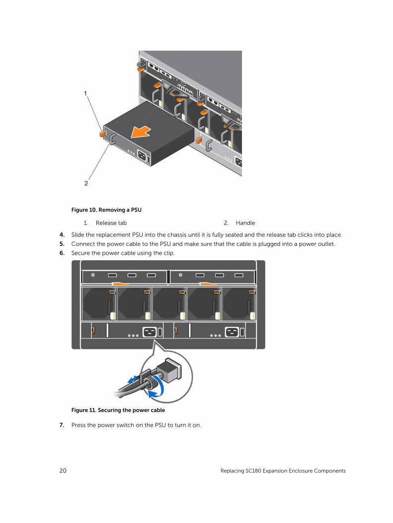
Figure 10. Removing a PSU
1. Release tab 2. Handle
4. Slide the replacement PSU into the chassis until it is fully seated and the release tab clicks into place.
5. Connect the power cable to the PSU and make sure that the cable is plugged into a power outlet.
6. Secure the power cable using the clip.
Figure 11. Securing the power cable
7. Press the power switch on the PSU to turn it on.
20 Replacing SC180 Expansion Enclosure Components

NOTE: Allow several seconds for the expansion enclosure to recognize the PSU and determine its status. When the PSU is functioning properly, the Power OK indicator turns green and the PSU fault and AC fault indicators are off.
8. In the Dell Storage Client, make sure that the replacement PSU is recognized and shown as up and running.
Next stepsUse SupportAssist to send diagnostic data to Dell Technical Support Services.
Replacing Cooling Fan ModulesThe SC180 expansion enclosure supports five cooling fan modules. If one cooling fan module fails, the remaining cooling fan modules continue to cool the expansion enclosure.
NOTE: When a cooling fan module fails, the cooling fan speed in the remaining modules increases significantly to provide adequate cooling. The cooling fan speed decreases gradually when a new cooling fan module is installed.
Identifying the Failed Cooling Fan Module
To determine which cooling fan module failed, use the Dell Storage Client.
1. Click the Hardware tab.
2. In the Hardware tab navigation pane, select and expand the failed storage system.
3. In the Hardware Alerts area, find the hardware alert that identifies the enclosure with the failed cooling fan.
Figure 12. Hardware Alert Identifying the Enclosure with the Failed Cooling Fan
4. In the Hardware tab navigation pane, expand the enclosure identified in the previous step.
5. Select Cooling Fans. The status of each cooling fan is displayed in the Cooling Fans tab.
6. Select the failed cooling fan. The location of the failed cooling fan module is displayed in the Fan View tab.
Replacing SC180 Expansion Enclosure Components 21
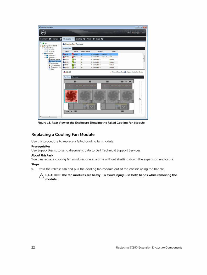
Figure 13. Rear View of the Enclosure Showing the Failed Cooling Fan Module
Replacing a Cooling Fan Module
Use this procedure to replace a failed cooling fan module.
PrerequisitesUse SupportAssist to send diagnostic data to Dell Technical Support Services.
About this taskYou can replace cooling fan modules one at a time without shutting down the expansion enclosure.
Steps
1. Press the release tab and pull the cooling fan module out of the chassis using the handle.
CAUTION: The fan modules are heavy. To avoid injury, use both hands while removing the module.
22 Replacing SC180 Expansion Enclosure Components
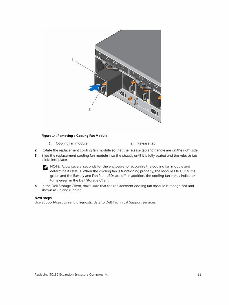
Figure 14. Removing a Cooling Fan Module
1. Cooling fan module 2. Release tab
2. Rotate the replacement cooling fan module so that the release tab and handle are on the right side.
3. Slide the replacement cooling fan module into the chassis until it is fully seated and the release tab clicks into place.
NOTE: Allow several seconds for the enclosure to recognize the cooling fan module and determine its status. When the cooling fan is functioning properly, the Module OK LED turns green and the Battery and Fan fault LEDs are off. In addition, the cooling fan status indicator turns green in the Dell Storage Client.
4. In the Dell Storage Client, make sure that the replacement cooling fan module is recognized and shown as up and running.
Next stepsUse SupportAssist to send diagnostic data to Dell Technical Support Services.
Replacing SC180 Expansion Enclosure Components 23
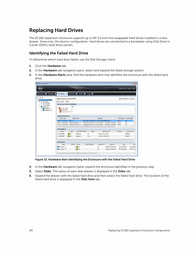
Replacing Hard DrivesThe SC180 expansion enclosure supports up to 84 3.5‐inch hot‐swappable hard drives installed in a two‐drawer, three‐row, 14‐column configuration. Hard drives are connected to a backplane using Disk Drive in Carrier (DDIC) hard drive carriers.
Identifying the Failed Hard Drive
To determine which hard drive failed, use the Dell Storage Client.
1. Click the Hardware tab.
2. In the Hardware tab navigation pane, select and expand the failed storage system.
3. In the Hardware Alerts area, find the hardware alert that identifies the enclosure with the failed hard drive.
Figure 15. Hardware Alert Identifying the Enclosure with the Failed Hard Drive
4. In the Hardware tab navigation pane, expand the enclosure identified in the previous step.
5. Select Disks. The status of each disk drawer is displayed in the Disks tab.
6. Expand the drawer with the failed hard drive and then select the failed hard drive. The location of the failed hard drive is displayed in the Disk View tab.
24 Replacing SC180 Expansion Enclosure Components

Figure 16. Inside Drawer View Showing the Failed Hard Drive
Replacing a Hard Drive
Use this procedure to replace a failed hard drive.
PrerequisitesUse SupportAssist to send diagnostic data to Dell Technical Support Services.
About this taskHard drives can be replaced one at a time without shutting down the expansion enclosure.
Steps
1. Find the SC180 and drawer that contains the failed drive. To identify the drawer with the failed driver, look for a drawer fault LED.
CAUTION: Before opening a drawer, ensure that the Dell Storage Client does not display a temperature warning. This issue must be corrected first to avoid potential drive failure and data loss.
2. Push and hold both drawer latches toward the center of the drawer and pull the drawer all the way out until it stops.
Replacing SC180 Expansion Enclosure Components 25
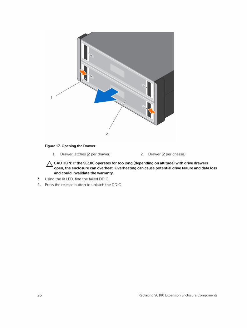
Figure 17. Opening the Drawer
1. Drawer latches (2 per drawer) 2. Drawer (2 per chassis)
CAUTION: If the SC180 operates for too long (depending on altitude) with drive drawers open, the enclosure can overheat. Overheating can cause potential drive failure and data loss and could invalidate the warranty.
3. Using the lit LED, find the failed DDIC.
4. Press the release button to unlatch the DDIC.
26 Replacing SC180 Expansion Enclosure Components

Figure 18. Removing the Drive from the Drawer
5. Wait about 10 seconds for the drive to spin down.
6. Slide the DDIC up and out until it is free of the DDIC slot.
NOTE: Leave the drive in the carrier. The replacement drive is also in a carrier, and attempting to remove the carrier can cause the carrier to break.
7. Install the replacement DDIC.
a. Hold the drive by the DDIC and slide it most of the way into the slot.
b. Using both hands (thumbs and forefingers), apply downward pressure firmly and equally across the DDIC.
Replacing SC180 Expansion Enclosure Components 27

Figure 19. Inserting the Drive into the Drawer
c. While maintaining downward pressure, slide the top plate of the DDIC toward the back of the drawer until it clicks in place.
Figure 20. Securing the Drive in the Drawer
28 Replacing SC180 Expansion Enclosure Components

NOTE: It is possible for a drive to appear seated but not be fully locked into position, eventually causing it to dislodge itself. After installing a drive, check the release button in the center of the DDIC. If the drive is NOT fully locked into position, a yellow line will be visible underneath the arrow button. If the yellow line is visible, remove the drive and re-install it.
CAUTION: If the DDIC fails to latch, do not use it and request a replacement from Dell Technical Support Services. If a faulty DDIC unlatches within a closed drawer, it can make the drawer unable to be opened.
8. Close the drawer.
a. Locate the two lock-release buttons situated midway along the runners on each side of the drawer.
b. Press the lock-release buttons inward and use your body to push the drawer toward the chassis until the locks disengage.
c. Place your hands on the front bezel and continue to push the drawer inward until the bezel is flush with the chassis and the front drawer locks engage.
Figure 21. Closing the Drawer
WARNING: Keep fingers clear of the chassis as the drawer is closed.
9. In the Dell Storage Client, make sure that the replacement hard drive is recognized and shown as up and running. If the Dell Storage Client informs you that there are unassigned hard drives, see the Dell Storage Manager Client Administrator’s Guide for instructions on managing unassigned hard drives.
NOTE: Allow several seconds for the enclosure to recognize the hard drive and determine its status. When the hard drive is functioning properly, the indicator turns green in the Dell Storage Client and the LED on the DDIC is off.
Next stepsUse SupportAssist to send diagnostic data to Dell Technical Support Services.
Replacing SC180 Expansion Enclosure Components 29
Replacing an Enclosure Management ModuleThe SC180 expansion enclosures support redundant hot-swappable Enclosure Management Modules (EMMs).
EMMs provide the following data path and enclosure management functions for the expansion enclosure:
• Monitoring and controlling expansion enclosure environment elements such as temperature, fan, power supplies, and expansion enclosure LEDs
• Controlling access to hard drives
• Communicating expansion enclosure attributes and states to Storage Center
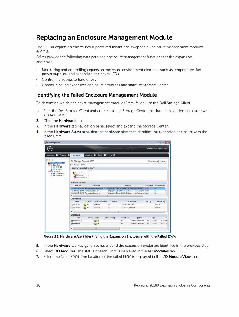
Identifying the Failed Enclosure Management Module
To determine which enclosure management module (EMM) failed, use the Dell Storage Client.
1. Start the Dell Storage Client and connect to the Storage Center that has an expansion enclosure with a failed EMM.
2. Click the Hardware tab.
3. In the Hardware tab navigation pane, select and expand the Storage Center.
4. In the Hardware Alerts area, find the hardware alert that identifies the expansion enclosure with the failed EMM.
Figure 22. Hardware Alert Identifying the Expansion Enclosure with the Failed EMM
5. In the Hardware tab navigation pane, expand the expansion enclosure identified in the previous step.
6. Select I/O Modules. The status of each EMM is displayed in the I/O Modules tab.
7. Select the failed EMM. The location of the failed EMM is displayed in the I/O Module View tab.
30 Replacing SC180 Expansion Enclosure Components

Figure 23. Rear View of the Expansion Enclosure Showing the Failed EMM
Replacing an Enclosure Management Module
Use this procedure to replace a failed EMM.
About this taskEMMs can be replaced one at a time without shutting down the storage system.
NOTE: Make sure the cables are labeled before disconnecting them from the EMM.
Steps
1. Use SupportAssist to send diagnostic data to Dell Technical Support Services.
2. Disconnect the SAS cables connected to the EMM.
3. Push the release tab to the right and pull the release lever away from the chassis.
4. Grasp the release lever and pull the EMM away from the chassis.
Replacing SC180 Expansion Enclosure Components 31

Figure 24. Replacing an EMM
1. EMM 2. EMM release tab and lever
5. Insert the replacement EMM into the bay until it is fully seated.
6. Push the release lever toward the chassis until it clicks into place.
7. Reconnect the SAS cables to the EMM.
Replacing Rack RailsRack rails are used to install the SC180 expansion enclosure into a rack.
Prerequisites
1. Use SupportAssist to send diagnostic data to Dell Technical Support Services.
2. Shut down the expansion enclosure using the Dell Storage Client.
About this task
NOTE: Replacing rack rails must be performed during a scheduled maintenance window when the Storage Center system is unavailable to the network.
Steps
1. Make sure all the cables are labeled.
2. Disconnect all the cables from the expansion enclosure.
3. Remove the plastic covers from the chassis ears.
4. Remove the screws that secure the chassis to the rack.
5. Remove the expansion enclosure from the rack rails.
32 Replacing SC180 Expansion Enclosure Components

WARNING: Do not attempt to the lift the expansion enclosure by yourself. Always have assistance when lifting the expansion enclosure. If installed above the lower 20U of a rack, a customer-provided mechanical lift must be used to avoid injury.
6. Remove the rack rails from the rack.
7. Install the replacement rack rails in the rack.
8. Install the expansion enclosure in the rack rails.
9. Start up the expansion enclosure and optional expansion enclosure.
Next steps
Post-Replacement ProceduresAfter replacing a component in the SC180 expansion enclosure, start up the SCv2080 storage controllers and the SC180 expansion enclosures if they were previously shut down, then use SupportAssist to send diagnostic data to Dell Technical Support Services.
Start Up the Storage System and Expansion Enclosure
If the storage system and expansion enclosure were previously shut down, perform this procedure to start them up.
1. Plug the power cables into the PSUs of the storage system and expansion enclosure.
2. Turn on the expansion enclosure by pressing the power switches on the PSUs.
NOTE: Always turn on the expansion enclosure before turning on the storage system.
3. Turn on the storage system by pressing the power switches on the PSUs.
4. Use the Dell Storage Client to make sure the replacement part is recognized and shown as up and running.
Send Diagnostic Data Using Dell SupportAssist
Use Dell SupportAssist to send diagnostic data to Dell Technical Support Services.
1. Use the Storage Client to connect to the Storage Center.
2. In the Summary tab, click Send SupportAssist Information Now, which is located under SupportAssist Actions in the Status pane. The Send SupportAssist Information Now dialog box opens.
3. Select Storage Center Configuration and Detailed Logs.
4. Click OK.
The Storage Client displays the status of the SupportAssist action. A second dialog box opens when the transfer of SupportAssist information has completed successfully.
5. Click OK.
6. (Optional) If the Storage Center is in maintenance mode, return it to normal operation.
Replacing SC180 Expansion Enclosure Components 33

3Troubleshooting SC180 ComponentsThis section contains basic troubleshooting steps for components inside the SC180 expansion enclosures.
Troubleshooting Cooling Fan ModulesTo troubleshoot cooling fan modules:
1. Check the status of the cooling fan module using the Dell Storage Client.
2. Determine the status of the cooling fan module LEDs.
If the cooling fan fault indicator is lit, the cooling fan module has failed.
3. Reseat the cooling fan module by removing and reinstalling it.
NOTE: Allow several seconds for the expansion enclosure to recognize the cooling fan module and determine its status.
Troubleshooting PSUsTo troubleshoot power supply units (PSUs):
1. Check the status of the PSU using the Dell Storage Client.
2. Determine the status of the PSU LEDs.
• If the PSU fault indicator is lit, the PSU has failed.
• If the Power OK LED is not lit, check the power cord and power source into which the power supply is plugged:
– Connect another device to the power source and check whether the device works.
– Connect the power cord to a different power source.
– Replace the power cord.
• If the AC fault LED is lit, this PSU is not supplying power, though the other PSU may still be supplying power.
3. Reseat the PSU by removing and reinstalling it.
NOTE: Allow several seconds for the expansion enclosure to recognize the PSU and determine its status.
Troubleshooting Hard DrivesTo troubleshoot hard drives:
1. Check the status of the hard drive using the Dell Storage Client.
2. Determine the status of the DDIC LED.
• If the DDIC fault LED is lit, the hard drive has failed.
34 Troubleshooting SC180 Components
• If the DDIC fault LED is not lit, proceed to the next step.
3. Check the connectors and reseat the DDIC.
CAUTION: Perform this step only on unmanaged drives or after you confirm that the particular drive contains no user data. The Fault LED alone is not an indication that you can safely remove the drive.
a. Remove the DDIC.
b. Check the DDIC and the backplane to ensure that the connectors are not damaged.
c. Reinstall the DDIC. Make sure that the DDIC makes contact with the backplane.
Troubleshooting EMMsUse these steps to troubleshoot Enclosure Management Modules (EMMs).
1. Check the status of the EMM using the Dell Storage Client.
2. Check the pins and reseat the EMM.
a. Remove the EMM.
b. Verify that the pins on the backplane and the EMM are not bent. If any pins are bent, do not attempt to correct them, instead, contact Dell Technical Support Services for further instruction.
c. Reinstall the EMM.
3. Determine the status of the EMM power and fault LEDs. If the fault LED is lit, the EMM has failed.
4. Verify link status. If the link status LEDs are not green, check the cables.
a. Reseat the cables on the expansion enclosure and storage system.
b. Recheck the link status LEDs. If the link status LEDs are not green, replace the cables.
5. Reseat the EMM by removing and reinstalling it.
NOTE: Allow several seconds for the expansion enclosure to recognize the EMM and determine its status.
Troubleshooting SC180 Components 35
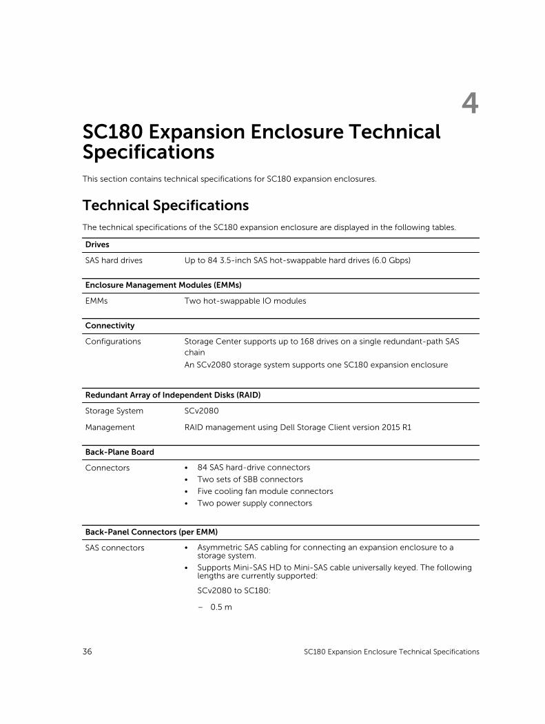
4SC180 Expansion Enclosure Technical SpecificationsThis section contains technical specifications for SC180 expansion enclosures.
Technical SpecificationsThe technical specifications of the SC180 expansion enclosure are displayed in the following tables.
Drives
SAS hard drives Up to 84 3.5-inch SAS hot-swappable hard drives (6.0 Gbps)
Enclosure Management Modules (EMMs)
EMMs Two hot-swappable IO modules
Connectivity
Configurations Storage Center supports up to 168 drives on a single redundant-path SAS chain
An SCv2080 storage system supports one SC180 expansion enclosure
Redundant Array of Independent Disks (RAID)
Storage System SCv2080
Management RAID management using Dell Storage Client version 2015 R1
Back-Plane Board
Connectors • 84 SAS hard-drive connectors
• Two sets of SBB connectors
• Five cooling fan module connectors
• Two power supply connectors
Back-Panel Connectors (per EMM)
SAS connectors • Asymmetric SAS cabling for connecting an expansion enclosure to a storage system.
• Supports Mini-SAS HD to Mini-SAS cable universally keyed. The following lengths are currently supported:
SCv2080 to SC180:
– 0.5 m
36 SC180 Expansion Enclosure Technical Specifications

Back-Panel Connectors (per EMM)
– 2 m
– 3 m
– 5 m
NOTE: SAS connectors are SFF-8086/SFF-8088 compliant.
LED Indicators
Front panel • One two-digit LCD indicator for Unit ID, error code, and unit location identifier
• One two-color LED indicator for power status
• One single-color LED indicator for module fault status (expansion enclosure as a whole)
• One single-color LED indicator for logical fault status (drive, HBA, RAID controller, and so on)
• One single-color LED indicator for drawer 1 fault status
• One single-color LED indicator for drawer 2 fault status
Drawer • One single-color LED indicator for sideplane card and power status
• One single-color LED indicator for drawer fault status
• One single-color LED indicator for logical fault status
• One single-color LED indicator for cable fault status
• Six single-color LED indicators for data transfer status
Disk Drive In Carrier (DDIC)
• One single-color LED for drive fault status
12 Gb SAS IO module 14 one-color LED status indicators, four each for the three SAS ports and two for the module status
Cooling module • One single-color LED indicator for module status
• One single-color LED indicator for battery fault status (not currently used)
• One single-color LED indicator for fan fault status
Power Supply Unit (PSU) • One single-color LED indicator for PSU fault status
• One single-color LED indicator for AC power fault status
• One single-color LED indicator for power status
Power Supplies
AC power supply (per power supply)
Wattage 2.8 kW
Voltage 200–240 VAC (16 A)
Heat dissipation 191-147 W
Input frequency 50/60 Hz
Max input power 1791 VA
Input current 7.4 A@241 VAC
SC180 Expansion Enclosure Technical Specifications 37

Power Supplies
Maximum inrush current Under typical line conditions and over the entire system ambient operating range, the inrush current may reach 55 A per power supply for 10 ms or less
Available Hard Drive Power (per Slot)
Supported hard drive power consumption (continuous)
Up to 1.16 A at +5 V
Up to 1.6 A at +12 V
IO Card Power (per Slot)
Maximum power consumed by IO Card
11 W at +12 V
Maximum available power
100 W at +12 V
Minimum available power
1 W at +5 V (standby)
Physical
Height 22.23 cm (8.8 inches)
Width 48.26 cm (19 inches)
Depth (front mounting bracket to rear surface)
91.44 cm (36 inches)
Depth (front surface to rear surface)
96 cm (38 inches)
Full Weight (maximum configuration)
130.1 kg (287 lb)
Weight without drives 62.1 kg (137 lb)
Environmental
NOTE: For additional information about environmental measurements for specific configurations, see dell.com/environmental_datasheets.
Temperature
Operating 5° to 35°C (41° to 95°F) with a maximum temperature gradation of 20°C per hour
NOTE: Maximum temperature of 35°C is reduced by 1°C per 300 meter (1°F per 547 feet) above 950 meters (3,117 feet)
Storage –40° to 65°C (–40° to 149°F) at a maximum altitude of 12,000 m (39,370 ft)
Relative humidity
Operating 10% to 80% (noncondensing) with 29°C (84.2°F) maximum dew point
38 SC180 Expansion Enclosure Technical Specifications
Environmental
Storage 5% to 95% (noncondensing) with 33°C (91°F) maximum dew point
Maximum vibration
Operating 0.21 G at 5–500 Hz for 15 min
Storage 1.04 G at 2–200 Hz for 15 min
Maximum shock
Operating Half-sine shock 5 G +/- 5% with a pulse duration of 10 ms +/- 10% in operational orientations only
Storage • Z-axis: 30 g 10 ms half sine
• X- and Y-axes: 20 g 10 ms half sine
Altitude
Operating 0 to 3048 m (–100 to 10,000 ft)
Storage –300 m to 12,192 m (–1000 ft to 39,370 ft)
Airborne Contaminant Level
Class G2 or lower as defined by ISA-S71.04-1985
SC180 Expansion Enclosure Technical Specifications 39