dell poweredge fn i/o module installation guide and the integrated dell remote access controller...
TRANSCRIPT

Dell PowerEdge FN I/O ModuleInstallation Guide

Notes, cautions, and warningsNOTE: A NOTE indicates important information that helps you make better use of your computer.
CAUTION: A CAUTION indicates either potential damage to hardware or loss of data and tells you how to avoid the problem.
WARNING: A WARNING indicates a potential for property damage, personal injury, or death.
Copyright © 2015 Dell Inc. All rights reserved. This product is protected by U.S. and international copyright and intellectual property laws. Dell™ and the Dell logo are trademarks of Dell Inc. in the United States and/or other jurisdictions. All other marks and names mentioned herein may be trademarks of their respective companies.
2015 - 09
Rev. A01

Contents
1 About this Guide....................................................................................................5Information Symbols............................................................................................................................. 5
Related Publications..............................................................................................................................6
2 Introduction...........................................................................................................7Product Description...............................................................................................................................7
3 Unpack the Switch................................................................................................8Unpacking Steps....................................................................................................................................8
4 Hardware Overview..............................................................................................9FN I/O Panel.......................................................................................................................................... 9
Power Supplies.................................................................................................................................... 10
Fans................................................................................................................................................ 10
Port Numbering...................................................................................................................................10
System Status.......................................................................................................................................10
5 Installation............................................................................................................12Before You Begin.................................................................................................................................12
Installing and Configuring the FN I/O Module................................................................................... 13
Installing the FN I/O Module in a PowerEdge Chassis.......................................................................13
Connecting a Console Terminal.........................................................................................................14
Auto-Configuration............................................................................................................................. 15
Stacking................................................................................................................................................15
Assembling a Switch Stack............................................................................................................ 16
Cabling the Switch Stack...............................................................................................................16
Programmable MUX Mode..................................................................................................................16
Full-switch Mode.................................................................................................................................16
6 Technical Specifications....................................................................................17IEEE Standards..................................................................................................................................... 17
7 Agency Compliance............................................................................................19USA Federal Communications Commission (FCC) Statement..........................................................19
Canadian Department of Communication Statement...................................................................... 19
European Union EMC Directive Conformance Statement................................................................19
European Community Contact.................................................................................................... 20
Japan: VCCI Compliance for Class A Equipment..............................................................................20
3

Korean Certification of Compliance...................................................................................................21
Safety Standards and Compliance Agency Certifications..................................................................21
Electromagnetic Compatibility (EMC)................................................................................................ 21
Product Recycling and Disposal.........................................................................................................22
8 Technical Support.............................................................................................. 24Accessing Dell Networking Technical Support................................................................................. 24
4

1About this GuideThis guide provides site preparation recommendations and step-by-step procedures for rack mounting, installing and replacing pluggable modules, and connecting to a power source.
After you have completed the hardware installation and power-up of the Dell PowerEdgeFN I/O Module, for software configuration information, see the Dell Networking Operating System (OS) Configuration Guide for the Dell PowerEdge FN I/O Module. For command line interface (CLI) information, see the Dell Networking OS Command Line Reference Guide for the Dell PowerEdge FN I/O Module.
CAUTION: To avoid electrostatic discharge (ESD) damage, wear grounding wrist straps when handling this equipment.
WARNING: Only trained and qualified personnel can install this equipment. Read this guide before you install and power up this equipment. This equipment contains two power cords. Disconnect both power cords before servicing.
WARNING: This equipment contains optical transceivers that comply with the limits of Class 1 laser radiation.
Figure 1. Class 1 Laser Product
WARNING: When no cable is connected, visible and invisible laser radiation may be emitted from the aperture of the optical transceiver ports. Avoid exposure to laser radiation and do not stare into open apertures.
Information SymbolsThis book uses the following information symbols:
NOTE: The Note icon signals important operational information.
CAUTION: The Caution icon signals information about situations that could result in equipment damage or loss of data.
WARNING: The Warning icon signals information about hardware handling that could result in injury.
About this Guide 5

WARNING: The ESD Warning icon requires that you take electrostatic precautions when handling the device.
Related Publications
For more information about the Dell PowerEdge FN I/O Module, see the following documents:
• Dell Networking OS Configuration Guide for the Dell PowerEdge FN I/O Module
• Dell Networking OS Command Line Reference Guide for the Dell PowerEdge FN I/O Module
• Dell Networking OS Release Notes for the Dell PowerEdge FN I/O Module
NOTE: For the most recent documentation and software, visit Dell Networking Technical Support (registration for access to some sections is required): http://www.dell.com/support/manuals.
6 About this Guide

2IntroductionThis document provides basic information about the Dell PowerEdge FN I/O Module , including how to install and perform the initial configuration.
For information about how to configure and monitor switch features, see the Dell Networking OS Configuration Guide for the Dell PowerEdge FN I/O Module. It is available on the Dell Support website at http://support.dell.com/manuals.
For information about how to bring up the switch features in the FN I/O Module, see the Dell Networking Configuration Guide for the Dell PowerEdge FN I/O Module, which is available on the Dell Support website at http://www.dell.com/support/manuals.
Product DescriptionThe FN I/O Module is a multi-layer, 12x10-Gigabit Ethernet system that operates in a Dell PowerEdge FX2 server chassis. It can support up to eight servers and two FN I/O modules with four uplink interfaces each.
A single chassis management controller (CMC) manages the Dell PowerEdge FX2 server. It is similar to the CMC unit on the Dell PowerEdge M1000e. It provides management connectivity to two FN I/O modules and the Integrated Dell Remote Access Controller (iDRAC) units of all eight servers.
NOTE:
By default, the FN I/O Module is in standalone mode. You can change the mode into Full Switch mode using the stack-unit stack-unit-id iom-mode full-switch command. For more information, see the Dell PowerEdge FN I/O Module Command Line Reference Guide.
Introduction 7

3Unpack the SwitchWhen unpacking each switch, make sure that the following items are included:
• One Dell PowerEdge FN I/O Module
• One USB type A-to-DB-9 female cable
• Getting Started Guide
• Safety and Regulatory Information
• Warranty and Support Information
• Software License Agreement
Unpacking Steps
NOTE: Before unpacking the switch, inspect the container and immediately report any evidence of damage.
1. Place the container on a clean, flat surface and cut all straps securing the container.
2. Open the container or remove the container top.
3. Carefully remove the switch from the container and place it on a secure and clean surface.
4. Remove all packing material.
5. Inspect the product and accessories for damage.
8 Unpack the Switch

4Hardware OverviewThis section contains information about device characteristics and modular hardware configurations for the Dell PowerEdge FN I/O Module.
FN I/O PanelAll fixed data ports (4 × 1/10G uplink ports) are on the FN I/O panel.
The FN I/O panel includes:
• Four fixed data ports
• USB Console port
• USB Storage port
• Light emitting diodes (LEDs)
Figure 2. FN I/O Panel
1 – USB Console Port
2 – USB Storage Port
3 – Activity and Link Status LEDs
4 – Four fixed data Ports
NOTE: The LED displays for system status are on both sides of the chassis. The fan and power status LEDs are on the Utility panel.
Hardware Overview 9

Power SuppliesThe Dell PowerEdge FX2 server chassis supports two hot-swappable power supply units (PSUs).
NOTE: You must install the PSUs at your site.
PSUs are field-replaceable. To ensure power redundancy and adequate cooling, install two power supplies in the switch. When running with full redundancy (two PSUs installed and running), you can remove and replace a PSU while the other PSUs are running without disrupting traffic.
Fans
The Dell PowerEdge FX2 server chassis supports eight fan trays.
NOTE: You must install the fans at your site.
Port NumberingWhen installed in a server enclosure, the Dell PowerEdge FN I/O Module ports are numbered from 1 to 12. Ports from 1 to 8 are internal server-facing ports. Ports from 9 to 12 are external ports numbered from the left to the right of the switch.
The following three types of stock keeping units (SKUs) are supported with the external interfaces on the front:
• FN 410S (4x10G SFP+)
• FN 410T (4x10G Base-T)
• FN 2210S (4x10G Combo ports with Ethernet and Fibre Channel)
The properties of the Combo card are:
• Ports 9 and 10 are fibre channel (FC) type and support 8 Gigabit FC, by default.
• Ports 11 and 12 are Ethernet type and support 10 Gigabit Ethernet, by default.
• To convert ports 9 and 10 to Ethernet type, use stack-unit <> portgroup 0 port-mode ethernet command.
To configure a port, specify the slot (from 0 to 5; default: 0) and port number (from 1 to 12) in the interface port-type slot/port command, where slot is the unit number of the FN I/O Module
displayed in the show system brief command. For example:
Dell(conf)# interface tengigabitethernet 0/4
System StatusYou can view the device status information in several ways, including LEDs and boot menu options.
You can also view status information through the show commands and with the simple network
management protocol (SNMP).The switch includes LED displays as shown in the following figure.
10 Hardware Overview

Figure 3. System LED Displays (FN I/O Panel)
1 — System Status LED
2 — System Power LED
The following table lists the LED definitions for the switch.
Table 1. System LED Displays
System LED LED Color/Display
Description
Power • Green
• Off
• Power is being supplied to the switch.
• The switch does not have power.
Status • Blue
• Off
• Amber
• The switch is operating normally as a standalone switch or as a stack master.
• The switch is not the stack master.
• A fault has occurred, or the switch is booting.
NOTE: The front-end ports also contain LEDs that provide information about the link status and traffic activity on a port.
NOTE: When the ingress air temperature exceeds 60°C, the Status LED turns amber and a major alarm is triggered.
Table 2. SFP+ and 10G BaseT Port LEDs
Label LED Color/Display
Description
Link LED • Off
• Solid green
• Solid amber
• The port is down.
• The port is up and can transmit traffic at maximum speed. An SFP+ or BaseT port can transmit at 10G.
• The port is up and is transmitting traffic at lower than maximum speed. An SFP+ or BaseT port is transmitting at 1G.
Activity LED • Off
• Blinking green
• No traffic is being transmitted or received on the port.
• Traffic is being transmitted or received on the port.
Hardware Overview 11

5InstallationThis switch installation procedure assumes the Dell PowerEdge FX2 server chassis is installed correctly. For complete instructions for installation, refer to the Dell PowerEdge FX2 server chassis Installation Guide.
Before You Begin
Before installing the switch, ensure that the chosen installation location meets the following site requirements:
• Clearance — There is adequate front and back clearance for operator access. Allow clearance for cabling, power connections, and ventilation.
• AC/DC power cord — The cord reaches from the power outlet to the Utility-panel connector.
• Cabling — The cabling is routed to avoid sources of electrical noise such as radio transmitters, broadcast amplifiers, power lines, and fluorescent lighting fixtures.
• Airflow — The airflow around the switch and through the vents is unrestricted.
• Ambient Temperature — The ambient switch operating temperature range is 10°C to 40ºC (50°F to 104ºF).
NOTE: Decrease the maximum temperature by 1°C (1.8°F) per 300 m (985 ft.) above 900 m (2955 ft.).
• Relative Humidity — The operating relative humidity is 8% to 85% (non-condensing) with a maximum humidity gradation of 10% per hour.
• Switch — The switch is installed in an environment as free as possible from dust and foreign conductive material (such as metal flakes from construction activities). Cooling mechanisms, such as fans and blowers in the switch, can draw dust and other particles causing contaminant buildup inside the chassis, which can result in system malfunction.
12 Installation
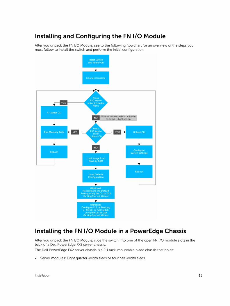
Installing and Configuring the FN I/O ModuleAfter you unpack the FN I/O Module, see to the following flowchart for an overview of the steps you must follow to install the switch and perform the initial configuration.
Installing the FN I/O Module in a PowerEdge ChassisAfter you unpack the FN I/O Module, slide the switch into one of the open FN I/O module slots in the back of a Dell PowerEdge FX2 server chassis.
The Dell PowerEdge FX2 server chassis is a 2U rack-mountable blade chassis that holds:
• Server modules: Eight quarter-width sleds or four half-width sleds.
Installation 13

• Switch modules: Two FN I/O modules or two pass-through modules.
Install server blades in the front of the chassis; install FN I/O modules in the back of the chassis.
Figure 4. Front View with Server Modules
Figure 5. Back View with Two FN I/O Modules
1 — CMC
After you slide the FN I/O Module in so that the connectors on the back of the blade are inserted into the chassis midplane, the switch automatically powers on. The CMC in the chassis validates that the switch blade is a supported FN I/O module before powering it on.
When the FN I/O Module powers on, the bootloader loads the image in the local flash memory. The image initializes the hardware and brings up the switch in operational mode.
Connecting a Console TerminalTo configure the switch, after the FN I/O Module powers on, complete all the external cabling connections and connect a terminal to the switch.
To monitor and configure the switch with the serial console, use the USB console port on the front panel of the switch to connect it to a VT100 terminal or to a computer running VT100 terminal emulation software. The console port is implemented as a data terminal equipment (DTE) connector.
To use the console port, you need the following equipment:
• VT100-compatible terminal, or a desktop, or a laptop computer with a serial port running VT100 terminal emulation software, such as Microsoft HyperTerminal.
• A serial cable (provided) with a USB type-A connector for the console port and DB-9 connector for the terminal.
To connect a terminal to the switch console port, perform the following tasks:
1. Connect the DB-9 connector on the serial cable to the terminal or computer running VT100 terminal emulation software.
2. Configure the terminal emulation software as follows:
14 Installation

a. To connect to the console, select the appropriate serial port (for example, COM 1) .
b. Set the data rate to 115200 baud.
c. Set the data format to 8 data bits, 1 stop bit, and no parity.
d. Set the flow control to none.
e. Set the terminal emulation mode to VT100.
f. Select Terminal keys for Function, Arrow, and Ctrl keys. Ensure that the setting is for Terminal keys (not Microsoft Windows keys).
The default enable password is calvin.
3. Connect the USB connector on the cable directly to the switch console port. The console port is on the left side of the front-end ports.
For information about how to access the CMC to configure the Dell PowerEdge FN I/O Module, see the Dell Chassis Management Controller (CMC) User’s Guide on the Dell Support website at http://www.dell.com/support/manuals. The CMC online help provides information about how to use the Web interface.
For more information about the FN I/O Module configuration, see the Dell Networking Configuration Guide for the Dell PowerEdge FN I/O Module.
Auto-ConfigurationAfter the FN I/O Module powers on, it auto-configures and is operational with the following software features enabled:
• VLANs: In Standalone mode, all ports are configured as members of all VLANs (4094). All VLANs are up and can send or receive Layer 2 traffic.
• Data center bridging capability exchange protocol (DCBX).
• Fiber Channel over Ethernet (FCoE) connectivity.
• FCoE initiation protocol (FIP) snooping.
• Hybrid ports: Ports are administratively up and auto-configured to operate as hybrid ports to transmit tagged and untagged VLAN traffic.
• Internet small computer system interface (iSCSI) optimization.
• Internet group management protocol (IGMP) snooping.
• Jumbo frames: Ports are set to a maximum transmission unit (MTU) of 12,000 bytes.
• Link aggregation: All uplink ports are configured in a single link aggregation group (LAG) (LAG 128).
• Link layer discovery protocol (LLDP): Enabled on all ports.
• Link tracking: Enables server-facing links to be brought up only if the uplink LAG is operationally up.
• NPIV Proxy Gateway: The default port mode of 2 FC and 2 Ethernet ports in FN 2210S provides NPIV Proxy Gateway functionality.
StackingIn the Dell PowerEdge FN I/O Module, the FN 410S and FN 410T support stacking. The FN 2210S does not support stacking.
The switch supports both ring and daisy-chain topology and stacking of the same type. FN 410S and FN 410T support two-unit in-chassis stacking and up to six units stacking across the chassis.
Installation 15

In Stack mode, the lower two external Ethernet ports (ports 9 and 10) operate as stack links. In Programmable MUX (PMUX) mode, you can configure any of the external Ethernet ports to operate as stack links.
Assembling a Switch Stack
After you complete the initial configuration, the FN I/O Module is powered up and operational.
FN 410S and FN 410T support two-unit in-chassis stacking and up to six units stacking across chassis.
Cabling the Switch Stack
Dell PowerEdge FN I/O Modules are connected to operate as a single stack in a ring topology using the SFP+ or Base-T ports on the front-end ports 9 and 10. To create a stack in either a ring or daisy-chain topology, you can use two units on the same chassis or up to six units across multiple chassis.
Prerequisite: Before you attach the stacking cables, all FN I/O Modules in the stack must be powered up with the default or reconfigured settings.
To connect stacking ports, use only Dell authorized cables (separately purchased). For example:
1. Insert a cable in port 9 on the first FN I/O Module.
2. Connect the cable to port 10 on the next FN I/O Module.
3. Continue this pattern on up to six FN I/O Modules.
4. Connect a cable from port 9 on the last FN I/O Module to port 10 on the first FN I/O Module. It creates a ring topology.
NOTE: The resulting topology allows the stack to function as a single switch with resilient failover capabilities.
Programmable MUX Mode
Standalone mode is the zero-touch auto-configuration default mode of the FN I/O Module. If you want the flexibility to configure different settings, change the FN I/O Module to PMUX mode. PMUX mode provides additional CLI commands to customize the software configuration as needed.
Full-switch Mode
All the commands and configurations supported on MXL is available in full-switch mode. Full-switch mode offers Layer 2/ Layer 3 switching functionalities on Dell FX2 chassis.
16 Installation

6Technical SpecificationsThe FN I/O Module is installed with the Dell PowerEdge FX2 server chassis for communication.
NOTE: Replace the battery only with the same or equivalent type. Dispose of the batteries according to the manufacturer's instructions.
Table 3. Environmental Parameters
Parameter Specifications
Operating temperature 20 °C/h (36 °F/h)
Storage temperature -40° to 158°F (-40° to 70°C)
Relative humidity
Storage humidity
5% to 95% RH with 33 °C (91 °F) maximum dew point. Atmosphere must be non-condensing at all times.
Maximum thermal output 475 BTU/hr
Maximum altitude
Operating
Storage
3048 m (10,000 ft)
12000 m (39,370 ft)
Table 4. Power Requirements
Parameter Specifications
Power supply 90–264 VAC 50/60 Hz
Maximum current draw per system 10A per power supply
Maximum power consumption 1920W (high Line) 900 (low line)
IEEE Standards
The FN I/O Module complies with the following IEEE standards:
• 802.3 CSMA/CD
• 802.3u 100BaseTx
• 802.3z (1000BaseSX)
• 802.3z/ab 1000BaseT
• 802.3ap 10GBase-KR
• 802.3x flow control
Technical Specifications 17

18 Technical Specifications

7Agency Compliance
USA Federal Communications Commission (FCC) Statement
This equipment has been tested and found to comply with the limits for a Class A digital device, under Part 15 of the FCC rules. These limits are designated to provide reasonable protection against harmful interference when the equipment is operated in a commercial environment. This equipment generates, uses, and can radiate radio frequency energy. If it is not installed and used in accordance to the instructions, it may cause harmful interference to radio communications. Operation of this equipment in a residential area is likely to cause harmful interference, in which case users will be required to take whatever measures necessary to correct the interference at their own expense. Properly shielded and grounded cables and connectors must be used in order to meet FCC emission limits. Dell Networking is not responsible for any radio or television interference caused by using other than recommended cables and connectors or by unauthorized changes or modifications in the equipment. Unauthorized changes or modification could void the user’s authority to operate the equipment. This device complies with Part 15 of the FCC Rules. Operation is subject to the following two conditions:
• This device may not cause harmful interference
• This device must accept any interference received, including interference that may cause undesired operation
Canadian Department of Communication Statement
European Union EMC Directive Conformance Statement
This product is in conformity with the protection requirements of EU Council Directive 2004/108/EC on the approximation of the laws of the Member States relating to electromagnetic compatibility. Dell Networking cannot accept responsibility for any failure to satisfy the protection requirements resulting from a nonrecommended modification of this product, including the fitting of non-Dell option cards.
This product has been tested and found to comply with the limits for Class A Information Technology Equipment according to CISPR 22/European Standard EN 55022. The limits for Class A equipment were
Agency Compliance 19

derived for commercial and industrial environments to provide reasonable protection against interference with licensed communication equipment.
WARNING: This is a Class A product. In a domestic environment, this device may cause radio interference, in which case, you may be required to take adequate measures.
European Community Contact
Dell Networking
EMEA — Central Dahlienweg 19
66265 Heusweiler
Germany
http://www.force10networks.com/german/
Japan: VCCI Compliance for Class A Equipment
WARNING: Use the AC power cords with Dell Networking equipment only. Do not use Dell Networking AC power cords with any unauthorized hardware.
This is Class A product based on the standard of the Voluntary Control Council For Interference by Information Technology Equipment (VCCI). If this equipment is used in a domestic environment, radio disturbance may arise. When such trouble occurs, the user may be required to take corrective actions.
20 Agency Compliance

Korean Certification of Compliance
Korean Package Label
Safety Standards and Compliance Agency Certifications
• CUS UL 60950-1, Second Edition
• CSA 60950-1-03, Second Edition
• EN 60950-1, Second Edition
• EN 60825-1, First Edition
• EN 60825-1 Safety of Laser Products — Part 1: Equipment Classification Requirements and User’s Guide
• EN 60825-2 Safety of Laser Products — Part 2: Safety of Optical Fibre Communication Systems
• FDA Regulation 21CFR 1040.10 and 1040.11
• IEC 60950-1, Second Edition, including all National Deviations and Group Differences
Electromagnetic Compatibility (EMC)
Emissions
• International: CISPR 22: 2006, Class A
• Australia/New Zealand: AS/NZS CISPR 22:2009, Class A
Agency Compliance 21

• Canada: ICES-003, Issue-4, Class A
• Europe: EN55022 2006 (CISPR 22: 2006), Class A
• Japan: VCCI V-3/2011.04 Class A
• USA: FCC CFR47 Part 15, Subpart B, Class A
Immunity
• EN 300 386 v1.5.1:2010 EMC for Network Equipment
• EN55022 2006, Class A
• EN 55024 1998 + A1: 2001 + A2: 2003
• EN 61000-3-2 Harmonic Current Emissions
• EN 61000-3-3 Voltage Fluctuations and Flicker
• EN 61000-4-2 ESD
• EN 61000-4-3 Radiated Immunity
• EN 61000-4-4 EFT
• EN 61000-4-5 Surge
• EN 61000-4-6 Low Frequency Conducted Immunity
Product Recycling and Disposal
You must recycle or discard this system according to applicable local and national regulations. Dell Networking encourages owners of information technology (IT) equipment to responsibly recycle their equipment when it is no longer needed. Dell Networking offers various product return programs and services in several countries to assist equipment owners in recycling their IT products.
Waste Electrical and Electronic Equipment (WEEE) Directive for Recovery, Recycle and Reuse of IT and Telecommunications Products
Dell Networking switches are labeled in accordance with European Directive 2002/96/EC concerning waste electrical and electronic equipment (WEEE). The Directive determines the framework for the return and recycling of used appliances as applicable throughout the European Union. This label is applied to various products to indicate that the product is not to be thrown away, but rather reclaimed upon end of life per this Directive.
Figure 6. The European WEEE symbol
In accordance with the European WEEE Directive, electrical and electronic equipment (EEE) is to be collected separately and to be reused, recycled, or recovered at end of life. Users of EEE with the WEEE marking per Annex IV of the WEEE Directive, as shown above, must not dispose of end of life EEE as unsorted municipal waste, but use the collection framework available to customers for the return, Specifications | 47 recycling and recovery of WEEE. Customer participation is important to minimize any
22 Agency Compliance

potential effects of EEE on the environment and human health due to the potential presence of hazardous substances in EEE.
Dell Networking products, which fall within the scope of the WEEE, are labeled with the crossed-out wheelie-bin symbol, as shown above, as required by WEEE.
For information on Dell Networking product recycling offerings, see the WEEE Recycling instructions on Dell Networking Technical Support at: http://downloads.dell.com/Manuals/all-products/esuprt_electronics/esuprt_docking_stations/dell-superspeed-usb3-dock-stn_Reference%20Guide_en-us.pdf?c=us&l=en&cs=&s=gen
Agency Compliance 23

8Technical SupportDell Networking Technical Support provides a range of documents and tools to assist you with effectively using Dell Networking equipment and mitigating the impact of network outages.
Accessing Dell Networking Technical SupportThe URL for Dell Networking Support is www.dell.com/support.
• On the Dell Networking Support page, enter your service tag if you have it. You can also access general support information from this page.
• http://www.dell.com/support/contents/us/en/04/category/Contact-Information/Technical-Support
24 Technical Support