dell emc powerstorethis guide is designed to help you prepare to configure your switches and...
TRANSCRIPT

Dell EMC PowerStoreNetwork Planning Guide
1.0
May 2020Rev. A01

Notes, cautions, and warnings
NOTE: A NOTE indicates important information that helps you make better use of your product.
CAUTION: A CAUTION indicates either potential damage to hardware or loss of data and tells you how to avoid the
problem.
WARNING: A WARNING indicates a potential for property damage, personal injury, or death.
© 2020 Dell Inc. or its subsidiaries. All rights reserved. Dell, EMC, and other trademarks are trademarks of Dell Inc. or itssubsidiaries. Other trademarks may be trademarks of their respective owners.

Additional Resources...................................................................................................................... 5
1 PowerStore models and network hardware overview....................................................................... 6Using this guide......................................................................................................................................................................6PowerStore deployment models..........................................................................................................................................7PowerStore appliance nodes................................................................................................................................................7Top-of-Rack (ToR) switches...............................................................................................................................................8
Dell EMC PowerSwitch S4148F-ON............................................................................................................................. 8Dell EMC PowerSwitch S4148T-ON............................................................................................................................. 9Dell PowerSwitch S5248F-ON...................................................................................................................................... 9
PowerStore logical topology...............................................................................................................................................10Top-of-Rack (ToR) switch connectivity options and requirements ............................................................................. 11
Switch to switch (L2) connectivity options................................................................................................................12Node to Top-of-Rack (ToR) switch connectivity requirements.............................................................................. 14
Part I: PowerStore T model: Network Planning................................................................................ 15
2 PowerStore T model out-of-band management switch.............................................................. 16PowerStore T model out-of-band management switch connectivity.....................................................................16
3 PowerStore T model: Network configuration requirements........................................................ 18PowerStore T model appliance networks................................................................................................................... 18PowerStore T model network VLAN requirements.................................................................................................. 20IP address requirements for initial configuration....................................................................................................... 20
4 Prepare to configure the networks.......................................................................................... 22Preparing to configure PowerStore............................................................................................................................ 22
Part II: PowerStore X model: Network Planning...............................................................................23
5 PowerStore X model: Network configuration requirements....................................................... 24PowerStore X model networks....................................................................................................................................24PowerStore X model networks VLAN options.......................................................................................................... 25IP addresses for network configuration .................................................................................................................... 26
6 Prepare to configure the networks.......................................................................................... 27Preparing to configure PowerStore............................................................................................................................ 27
A Discovering PowerStore Appliances.............................................................................................28Discover your system..........................................................................................................................................................28
Discovery with a direct connection.............................................................................................................................28Discovery with remote connection............................................................................................................................. 29
Contents
Contents 3

B PowerStore Network Setup Preparation Worksheets.................................................................... 30PowerStore T model: Network Setup Preparation Worksheet (blank)....................................................................... 30PowerStore T model: example of completed Network Setup Preparation Worksheet............................................. 32PowerStore X model Network Setup Preparation Worksheet (blank)........................................................................ 34PowerStore X model: example of completed Network Setup Preparation Worksheet.............................................36
C PowerStore Initial Configuration Worksheets............................................................................... 39PowerStore Initial Configuration Worksheet (blank)......................................................................................................39PowerStore T model: example of a completed Initial Configuration Worksheet......................................................... 41PowerStore X model: example of a completed Initial Configuration Worksheet........................................................ 44
4 Contents

Additional ResourcesAs part of an improvement effort, revisions of the software and hardware are periodically released. Some functions that are described inthis document are not supported by all versions of the software or hardware currently in use. The product release notes provide the mostup-to-date information about product features. Contact your technical support professional if a product does not function properly ordoes not function as described in this document.
Where to get helpSupport, product, and licensing information can be obtained as follows:
• Product information
For product and feature documentation or release notes, go to the PowerStore Documentation page at www.dell.com/powerstoredocs.
• Troubleshooting
For information about products, software updates, licensing, and service, go to www.dell.com/support and locate the appropriateproduct support page.
• Technical support
For technical support and service requests, go to www.dell.com/support and locate the Service Requests page. To open a servicerequest, you must have a valid support agreement. Contact your Sales Representative for details about obtaining a valid supportagreement or to answer any questions about your account.
Preface
Additional Resources 5

PowerStore models and network hardwareoverview
This chapter includes the following information.
Topics:
• Using this guide• PowerStore deployment models• PowerStore appliance nodes• Top-of-Rack (ToR) switches• PowerStore logical topology• Top-of-Rack (ToR) switch connectivity options and requirements
Using this guideThis guide is designed to help you prepare to configure your switches and networks for PowerStore.
This document provides guidelines and requirements to allow you to reserve the necessary resources, and make decisions about how youwill deploy your switches and networks for PowerStore. The PowerStore Network Configuration Guide for Dell PowerSwitch Seriesprovides specific steps for deploying both PowerStore T model appliances and PowerStore X model appliances with Dell PowerSwitchSeries. If you are not deploying with Dell PowerSwitch Series, then see your proprietary documentation for specific steps.
What is included in this guideThis document begins with the PowerStore models and network hardware overview chapter followed by the following two parts.
Table 1. Part descriptions
Part Chapters Description
Part 1: Deploying PowerStore T modelSwitches and Networks
2 - 4 Describes the guidelines and requirements to configure the switches andnetworks for PowerStore T model deployments.
Part 2: Deploying PowerStore X modelSwitches and Networks
5 - 7 Describes the guidelines and requirements to configure the switches andnetworks for PowerStore X model deployments.
Refer to PowerStore deployment models in the following section for descriptions of the different PowerStore deployment models.
Hardware demonstrated in this guideWhile there are different deployment options, this guide describes the requirements to deploy PowerStore with:
• A single cluster consisting of one appliance with a single base enclosure• Two Top-of-Rack (ToR) switches• One out-of-band (OOB) management switch for PowerStore T model deployments
NOTE: PowerStore X model deployment is not supported with an OOB management switch.
Supporting documentationIn addition to reading through this document, you should also read through the following guides, prior to configuring your switches andnetworks:
• PowerStore Planning Guide
1
6 PowerStore models and network hardware overview

• PowerStore Hardware Information Guide
PowerStore deployment modelsThe different PowerStore models support different types of storage.
Table 2. PowerStore deployment models
Deployment Model numbers Supported configuration Refer to
PowerStore T modelappliance
• 1000T• 3000T• 5000T• 7000T• 9000T
Supports block (Storage Area Network (SAN)), file(Network Attached Storage (NAS)), and VirtualVolume (vVol) workloads with the software stackdeployed directly on the bare metal of the system.
NOTE: Hypervisor deployments are notsupported on this model.
Part 1: Deploying PowerStore Tmodel Switches and Networks
PowerStore X modelappliance
• 1000X• 3000X• 5000X• 7000X• 9000X
Supports block (SAN-only), and vVol workloadswith a hypervisor installed on the system. Thesystem software is deployed on the hypervisor,which enables deployment of virtual machines(VMs) and customer applications within thehardware.
NOTE: File (network attached storage(NAS)) services are not supported on thismodel.
Part 2: Deploying PowerStore Xmodel Switches and Networks
PowerStore appliance nodesPowerStore appliances are deployed with a minimum of one base enclosure. Each base enclosure consists of two nodes.
A base enclosure consists of two nodes. Node A is the bottom node and Node B is the top node (flipped upside down in enclosure). Theport layouts on both nodes are the same.
12
3
4 4
4 4
2
3 1
2
4-port cardManagement ports
Service portsI/O Module
1 3
4
Figure 1. PowerStore base enclosure nodes and ports
0 1 2 3
0123
Figure 2. 4-Port card port numbers
PowerStore models and network hardware overview 7

NOTE: The examples used in this guide describe how to cable port 0 and port 1 of the 4 port card on the base enclosure
nodes. See the PowerStore Clustering and High Availability White Paper for specific steps to add more ports to provide
additional bandwidth and fault tolerance.
Top-of-Rack (ToR) switchesPowerStore requires connectivity to a pair of Top-of-Rack (ToR) switches to ensure high availability.
NOTE: While the switches are referred to as Top-of-Rack (ToR) switches, they do not need to be installed at the top-of-
the PowerStore hardware rack.
Supported switchesSee the PowerStore Support Matrix for the list of supported switches. The Support Matrix is available from the Dell support siteat:www.dell.com/support.
Deploying with PowerSwitch SeriesPowerStore can be purchased with the following Dell EMC PowerSwitch Series running OS10 Enterprise Edition (OS10EE).
• S4148F-ON• S4148T-ON• S5248F-ON
For further information about the Dell PowerSwitch Series running Operating System 10 Enterprise Edition (OS10EE) refer to thefollowing documents.
Table 3. PowerSwitch documentation resources
Document Reference Location
Dell EMC PowerSwitch S4100-ON Series Installation Guide
PowerSwitch site preparation requirements,step-by-step procedures for rack mountingand desk mounting, inserting modules, andconnecting to a power source.
For Dell EMC S4148F-ON, and S4148T-ONswitches go to the Dell EMC PoweSwitchS4148-ON/S4148T-ON/S4148FE-ONDocumentation page at:
https://www.dell.com/support/home/us/en/04/product-support/product/networking-s4148f-on/docs
For Dell EMC S5248F-ON switches go to thePowerSwitch S5248F-ON Documentation pageat:
https://www.dell.com/support/home/us/en/04/product-support/product/networking-s5248f-on/docs
S5200F-ON Series InstallationGuide
OS10 Enterprise Edition UserGuide
Contains the necessary steps to install theoperating system, access the switch remotely,and run the switch commands.
Dell EMC PowerSwitch S4148F-ONConnectivity to PowerStore nodes is through the ports on the I/O panel.
Figure 3. S4148F-ON switch I/O Panel
• 48x10GbE• 4x10/25/40/50/100GbE
Connectivity to S4000 series switches from a jumpbox or laptop is done through the serial console port.
8 PowerStore models and network hardware overview

Serial Console Port
Management Port
Figure 4. S4000 series PSU-side
Dell EMC PowerSwitch S4148T-ONConnectivity to PowerStore nodes is through the ports on the I/O panel.
Figure 5. S4148T-ON switch I/O-side
• 48x10 GBASE-T• 4x10/25/40/50/100GbE
Connectivity to S4000 series switches from a jumpbox or laptop is done through the serial console port.
Serial Console Port
Management Port
Figure 6. S4000 series PSU-side
Dell PowerSwitch S5248F-ONYou can configure PowerStore with dual Dell PowerSwitch S5248F-ON switch models.
Figure 7. S5248F-ON I/O-side
• 48x25GbE• 4x10/25/40/50/100GbE
Connectivity to S5000 series switches from a jumpbox or laptop is done through the serial console port.
PowerStore models and network hardware overview 9

Serial Console Port
Management Port
Figure 8. S5248 PSU-side
PowerStore logical topologyThe following diagrams demonstrate the logical network topology for a PowerStore T model deployment, and a PowerStore X modeldeployment.
PowerStore T model logical topology
PowerStore T base enclosure
Management Production
Embedded module
Embedded module
ToR 2ToR 1
Storage
Internal
NAS
Remote Discovery
Management
Management VLANS or Subnets Production VLANS or Subnets
Figure 9. PowerStore T model logical topology and network paths
10 PowerStore models and network hardware overview

PowerStore X model logical topology
PowerStore X base enclosure
ToR 1
Embedded module
ToR 2
Embedded module
Management Production
Storage
Internal
Remote Discovery
Management
Management VLANS or Subnets Production VLANS or Subnets
vMotion
Figure 10. PowerStore X model logical topology and network paths
Top-of-Rack (ToR) switch connectivity optionsand requirementsPowerStore requires connectivity to a pair of Top-of-Rack (ToR) switches.
This section describes the requirements for:
• Switch to switch (L2) connectivity• Node to ToR switch connectivity
NOTE: PowerStore T model deployments also require connectivity to at least one out-of-band management switch. See
PowerStore T model appliance out-of-band management switch requirements for details.
PowerStore models and network hardware overview 11

Switch to switch (L2) connectivity optionsIt is recommended to use one of the following options to connect the switches together.
Table 4. Switch to switch interconnect options
Switch interconnect options Recommendation
1. Multi-chassis Link AggregationGroup (MC-LAG)
Dell highly recommends using MC-LAG for connectivity between the switches.
2. Reliable L2 uplinks If MC-LAG is not an option, then the next best recommended connectivity between the switches isto use reliable L2 uplinks.
NOTE: If neither MC-LAG or reliable L2 uplinks is an option, you can use a Direct Trunk Link, but this is not
recommended.
Multi-chassis Link Aggregation Group (MC-LAG) interconnectIt is highly recommended that you deploy PowerStore with an MC-LAG interconnect between the two ToR switches.
In an MC-LAG environment, the two switches are treated as one logical switch. This allows you to add all the uplinks from both switchesinto a single port channel that will span the MC-LAG.
Layer 3 – Core UplinksUplink A Uplink B
Layer 2 – ToR SwitchesPort Channel
MC-LAG Interconnect
Figure 11. ToR switches with MC-LAG interconnect
NOTE: Port location for the reliable high speed uplinks may change depending on switch vendor or model.
MC-LAG is a switch interconnection technology that joins a number of independent Top-of-Rack (ToR) switches into a single virtualchassis. MC-LAG allows the link aggregation (LAG) port groups to span multiple chassis, enabling better resilience of the LAG connection.Additionally, MC-LAG enables traffic going from switch to switch using the full bandwidth of the available connection, without usingspanning tree protocol (STP), which would disable some links to prevent loops.
MC-LAG is a general name for the technology, however certain vendors use their own proprietary terminology to define MC-LAGconnectivity.
Table 5. Vendor specific MC-LAG technology
Vendor Proprietary MC-LAG technology
Dell Virtual Link Trunking (VLT)
12 PowerStore models and network hardware overview

Table 5. Vendor specific MC-LAG technology(continued)
Vendor Proprietary MC-LAG technology
Cisco Virtual PortChannel (vPC)
Brocade Multi-Chassis Trunking (MCT)
NOTE: Refer to your vendor's documentation to determine their technology for MC-LAG.
MC-LAG connectivity requirements are:
• A minimum of two connection cables in parallel with a high speed reliable connection.• Connections must be made through the high speed ports on the switch. Verify with your switch provider documentation where the
high speed ports are located on your switch.• Use two cables that support connectivity between the high speed ports. For example 100Gbps Direct Attached Cables (DAC) would
be required to connect the MC-LAG ports together.
Reliable L2 uplink interconnectUsing a reliable L2 (Ethernet level) connection through the uplinks to connect the ToR switches is an acceptable alternative to MC-LAGfor PowerStore deployments.
With a reliable L2 connection you can port-channel the uplinks on each physical switch, which requires creating two port-channels insteadof one.
Layer 3 – Core UplinksUplink A Uplink B
Layer 2 – ToR SwitchesPort ChannelPort Channel
Figure 12. ToR switches with reliable L2 uplink interconnect
NOTE: Port location for the reliable high speed uplinks may change depending on switch vendor or model.
Reliable L2 uplinks require redundant, high speed connections.
PowerStore models and network hardware overview 13

Node to Top-of-Rack (ToR) switch connectivityrequirementsA dual switch topology requires that each of the base enclosure appliance nodes have at least one connection to each of the Top-of-Rack(ToR) switches to provide redundancy at the NIC and switch levels.
Figure 13. Node to ToR switch cabling
When cabling the nodes to the switches:
• Port 0 and Port 1 on the same node must connect to opposite switches• Port 0 on Node A, and Port 0 on Node B must connect to opposite switches• Port 1 on Node A, and Port 1 on Node B must connect to opposite switches
14 PowerStore models and network hardware overview

PowerStore T model: Network Planning
Topics:
• PowerStore T model out-of-band management switch• PowerStore T model: Network configuration requirements• Prepare to configure the networks
I
PowerStore T model: Network Planning 15

PowerStore T model out-of-bandmanagement switch
This chapter includes the following information.
Topics:
• PowerStore T model out-of-band management switch connectivity
PowerStore T model out-of-band managementswitch connectivityIn addition to the two Top-of-Rack (ToR) switches required for all PowerStore T model deployments, connectivity to an out-of-band(OOB) management switch is required for system management and discovery.
Node to out-of-band management switchThe out-of-band (OOB) management switch is connected through the 1 GbE management port on each of the appliance base enclosurenodes as demonstrated in the following diagram.
Figure 14. Connection to the OOB management switch
• Deployment with at least one OOB management switch is required.• The OOB management switch can be configured with or without a management VLAN.• The OOB management switch ports must support untagged native VLAN traffic for remote discovery.
See PowerStore T model appliance networks. in the following chapter for a description of the networks which run over the managementswitch.
OOB management switch uplink connectionsThe following image shows an example of an OOB management switch that connects to two Layer 3 uplink devices. Both of theconnections are connected with a port-channel that offer increased bandwidth and redundancy.
2
16 PowerStore T model out-of-band management switch

Layer 3 – Management UplinksManagement
Uplink A
Port Channel
Management Uplink B
Layer 3 – OOB Management Switch
Figure 15. Out-of-band management switch uplink connections
PowerStore T model out-of-band management switch 17

PowerStore T model: Network configurationrequirements
This chapter includes the following information.
Topics:
• PowerStore T model appliance networks• PowerStore T model network VLAN requirements• IP address requirements for initial configuration
PowerStore T model appliance networksPowerStore T model requires all networks to be unique. It is highly recommended to deploy PowerStore T model with multiple and uniqueVLANs to separate the traffic. However, if only one VLAN is available, you have the option to deploy PowerStore T model with a singleVLAN and multiple unique subnets as demonstrated below.
PowerStore T base enclosure
Management Production
Embedded module
Embedded module
ToR 2ToR 1
Storage
Internal
NAS
Remote Discovery
Management
Management VLANS or Subnets Production VLANS or Subnets
Figure 16. PowerStore T model network traffic
3
18 PowerStore T model: Network configuration requirements

Ensure that the PowerStore T model system interfaces are able to communicate to each other through the VLANs shown above. Consultyour network vendor documents to ensure all proper L2 and/or L3 traffic is being routed properly for all networks that PowerStore Tmodel is utilizing.
Table 6. PowerStore T model networks
VLAN or Subnet Description Switch used Node transport ports
Remote discovery network is generatedautomatically by the system and isbroadcasted as untagged traffic over themanagement port. This network is used bythe Discovery Utility that is running on aworkstation.
Out-of-bandmanagement
Dedicated 1 GbE Management
Management network traffic which providesaccess to:
• Infrastructure services such as DNS, NTP,and SMTP.
• PowerStore REST API, PowerStoreManager, and PowerStore CLI
• SupportAssist
Out-of-bandmanagement
Dedicated 1 GbE Management
Storage network (block) traffic and externaldata mobility traffic such as replication, andstorage import. PowerStore T model iSCSItarget portals for front-end traffic.
Top-of-Rack (ToR)switch
First 2 ports of the 4-port card(LACP bond)
Network attached storage (file) front-endaccess such as NFS, SMB, and FTP.
ToR switch First 2 ports of the 4-port card(LACP bond)
The internal network communication occurson the Native VLAN. The internal network isused:
• To manage internal communication suchas to the cluster database, and betweenappliances within a cluster. The intra-cluster management network is encryptedwith IPSEC.
• For intra-cluster data mobility traffic suchas storage migration between appliances.
• For node-to-node communication toenable file services when operating in"Unified," mode.
ToR switch First 2 ports of the 4-port card(LACP bond)
While configuring your networks, also note the following:
• For multi-appliance cluster configurations, ensure the Internal network as shown above has proper L2 and/or L3 routing on the nativeVLAN such that the first 2 ports of the 4-port card can communicate to other appliances on the network.
• If deploying with file services IPv6 is must be enabled on the ToR switches through the native VLAN.
Network configuration in PowerStoreAll PowerStore networks must be configured on the switch. The networks are configured in PowerStore as follows:
• Management network must be created the first time you create a cluster through the PowerStore Initial Configuration Wizard.• Storage network can be created for iSCSI traffic the first time you create a cluster through the PowerStore Initial Configuration
Wizard (ICW). However, you have the option of skipping this step in the ICW if you're using Fibre Channel only. If you want to add thestorage network later in PowerStore Manager, REST API, or CLI". See the Dell EMC PowerStore Clustering and High AvailabilityWhite Paper for details.
• NAS server networks are created through the PowerStore Manager, REST API, or CLI after the initial cluster is created in PowerStoreT model.
PowerStore T model: Network configuration requirements 19

PowerStore T model network VLAN requirementsThe following table shows an example of the different type of networks with sample VLAN IDs in a PowerStore T model appliance.
Table 7. PowerStore T model VLAN configuration
SampleVLAN ID
Network Switch used VLAN Ports Subnet
100 Remote Discovery (runs over the Native VLAN) Out-of-band management Untagged 169.254.x.x/16
100 Management Out-of-band management Untagged y.y.y.y/24
200 Storage Top-of-rack (ToR) switch Tagged y.y.x.y/24
300 NAS serversNOTE: You can use multiple VLANs ifyou are running multiple NAS networks
ToR switch Tagged y.y.z.y/24
1 Internal (runs over the Native VLAN) ToR switch Untagged Internal IPv6 addressing
Untagged trafficIf you want to use the native VLAN for any of your PowerStore networks, you must enter VLAN ID 0 (zero) for any untagged traffic in thePowerStore Initial Configuration Wizard. PowerStore uses VLAN 0 as a marker for untagged traffic. When you set the VLAN ID tozero, the network traffic is not tagged (based on the 802.1q standard), and the network takes on the native VLAN. The traffic on thatnetwork is passed as untagged in PowerStore, and the Native VLAN is applied to the untagged traffic through the switch.
IP address requirements for initial configurationYou will need IP addresses to configure the management, and storage networks in PowerStore T model.
Management and storage network IP addressrequirementsYou will need IP addresses to configure the management and storage networks in PowerStore T model through the Initial ConfigurationWizard (ICW). The ICW runs automatically the first time you discover PowerStore T model.
Table 8. PowerStore T model IP address requirements
Network IP Addresses Required
Management Network Per Appliance Node A 1
Node B 1
Appliance 1
Total Required Per Appliance for Management 3
Per Cluster Cluster IP Address 1
Total Required Per VLAN or Subnet for Management 4
Storage Network(optional)
Per Appliance Node A iSCSI Target 1
Node B iSCSI Target 1
Total Required Per Appliance for Storage 2
Per Cluster Global Storage Discovery IPAddress (optional)
1
Total Required Per VLAN or Subnet for Storage 3
20 PowerStore T model: Network configuration requirements
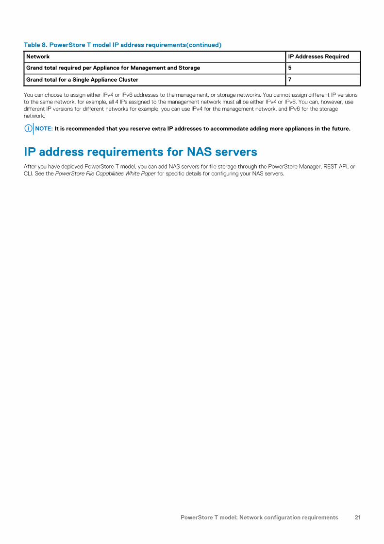
Table 8. PowerStore T model IP address requirements(continued)
Network IP Addresses Required
Grand total required per Appliance for Management and Storage 5
Grand total for a Single Appliance Cluster 7
You can choose to assign either IPv4 or IPv6 addresses to the management, or storage networks. You cannot assign different IP versionsto the same network, for example, all 4 IPs assigned to the management network must all be either IPv4 or IPv6. You can, however, usedifferent IP versions for different networks for example, you can use IPv4 for the management network, and IPv6 for the storagenetwork.
NOTE: It is recommended that you reserve extra IP addresses to accommodate adding more appliances in the future.
IP address requirements for NAS serversAfter you have deployed PowerStore T model, you can add NAS servers for file storage through the PowerStore Manager, REST API, orCLI. See the PowerStore File Capabilities White Paper for specific details for configuring your NAS servers.
PowerStore T model: Network configuration requirements 21

Prepare to configure the networks
This chapter contains the following information.
Topics:
• Preparing to configure PowerStore
Preparing to configure PowerStorePrior to deployment work with your network administrator to reserve the network resources required for deployment.
Blank worksheets have been provided in this document to assist you with reserving network resources.
• Appendix B: PowerStore Network Setup Preparation Worksheet • Appendix C: PowerStore Initial Configuration Worksheets
Deployment with Dell PowerSwitch SeriesIf you are deploying PowerStore with Dell PowerSwitch Series, see the PowerStore Network Configuration Guide for Dell PowerSwitchSeries guide for examples, and steps to deploy your PowerStore networks. A completed Network Setup Preparation Worksheet has beenprovided for you to use with the steps provided in the PowerStore Network Configuration Guide for Dell PowerSwitch Series.
A completed Initial Configuration Worksheets has also been provided for your reference.
Deployment with third-party switchesIf you are deploying PowerStore with third-party switches refer to the proprietary switch documentation to configure the switches forPowerStore.
4
22 Prepare to configure the networks
PowerStore X model: Network Planning
Topics:
• PowerStore X model: Network configuration requirements• Prepare to configure the networks
II
PowerStore X model: Network Planning 23

PowerStore X model: Network configurationrequirements
This chapter includes the following information.
Topics:
• PowerStore X model networks• PowerStore X model networks VLAN options• IP addresses for network configuration
PowerStore X model networksPowerStore X modelrequires all networks to be unique. It is highly recommended to deploy PowerStore X model with multiple and uniqueVLANs to separate the traffic. However, if only one VLAN is available, you have the option to deploy PowerStore X model with a singleVLAN and multiple unique subnets as demonstrated below.
PowerStore X base enclosure
ToR 1
Embedded module
ToR 2
Embedded module
Management Production
Storage
Internal
Remote Discovery
Management
Management VLANS or Subnets Production VLANS or Subnets
vMotion
Figure 17. PowerStore X model network traffic
5
24 PowerStore X model: Network configuration requirements

Ensure that the PowerStore X model interfaces are able to communicate to each other through the VLANs shown above. Consult yournetwork vendor documents to ensure all proper L2 and/or L3 traffic is being routed properly for all networks that PowerStore X model isutilizing.
Table 9. PowerStore X model networks
Network Types of traffic Node transport ports
Initial discovery using the PowerStore Discovery Utility. First port of the 4 port card
Management network traffic which provides access to:
• Infrastructure services such as DNS, NTP, and SMTP.• PowerStore REST API, PowerStore Manager, and PowerStore CLI• SupportAssist• vCenter
First 2 ports of the 4 port card(active/active)
Storage network (block) traffic and external data mobility traffic such asreplication, and storage import. PowerStore iSCSI target portals forfront-end traffic.
Second port of the 4-port card isactive, and the second port is used forbackup.
ESXi iSCSI initiator traffic. First 2 ports of the 4 port card
Network used for virtual machine (VM) migration. Second port of the 4-port card isactive, and the second port is used forbackup
The internal network communication occurs on the Native VLAN. Theinternal network is not currently used in this release.
First 2 ports of the 4-port card
Network configuration in PowerStoreAll PowerStore networks must be configured on the switch. Management, Storage, and vMotion networks are configured in PowerStorethe first time you create a cluster through the PowerStore Initial Configuration Wizard (ICW).
PowerStore X model networks VLAN optionsThe following table shows an example of the different type of networks with sample VLAN IDs in a PowerStore X model appliance.
Table 10. PowerStore X model VLAN configuration
Sample VLAN ID Network VLAN Ports Subnet example
1 Remote Discovery (runs over the Native VLAN) Untagged 169.254.x.x/16
100 Management Tagged y.y.y.y/24
200 Storage Tagged y.y.x.y/24
400 vMotion Tagged y.y.a.y/24
1 Internal (runs over the Native VLAN) Untagged Internal IPv6 addressing
Untagged trafficIf you want to use the native VLAN for any of your PowerStore networks, you must enter VLAN ID 0 (zero) for any untagged traffic in thePowerStore Initial Configuration Wizard. PowerStore uses VLAN 0 as a marker for untagged traffic. When you set the VLAN ID tozero, the network traffic is not tagged (based on the 802.1q standard), and the network takes on the native VLAN. The traffic on thatnetwork is passed as untagged in PowerStore, and the Native VLAN is applied to the untagged traffic through the switch.
PowerStore X model: Network configuration requirements 25

IP addresses for network configurationYou will need IP addresses to configure the networks in PowerStore X model through the Initial Configuration Wizard (ICW) whichruns automatically after you discover PowerStore X model.
Table 11. Initial configuration IP address requirements
Network IP Addresses Required
Management Network Per Appliance Node A 1
Node B 1
Appliance 1
ESXi Host for Node A 1
ESXi Host for Node B 1
Total Required Per Appliance for Management 5
Per Cluster Cluster IP Address(Management Network)
1
Total Required Per VLAN or Subnet for Management 6
Storage Network Per Appliance Node A iSCSI Target 1 minimum, 2recommended*
Node B iSCSI Target 1 minimum, 2recommended*
ESXi Node A iSCSI Initiator 2
ESXi Node B iSCSI Initiator 2
Total Required Per Appliance For Storage 6 minimum, 8recommended
Per Cluster (optional) Global StorageDiscovery IP Address(Storage Network)
1
Total Required Per VLAN or Subnet for Storage 7 minimum, 9recommended
vMotion Network Per Appliance Node A 1
Node B 1
Total Required Per VLAN or Subnet for vMotion 2
Grand total required per Appliance for Management, Storage, and vMotion 13 minimum, 15recommended
Grand total for a Single Appliance Cluster 15 minimum, 17recommended
You can choose to assign either IPv4 or IPv6 addresses to the management, storage, or vMotion networks. You cannot assign different IPversions to the same network, for example, all 5 IPs assigned to the management network must all be either IPv4 or IPv6. You can usedifferent IP versions for different networks for example, you can use IPv4 for the management network, and IPv6 for the storagenetwork.
26 PowerStore X model: Network configuration requirements

Prepare to configure the networks
This chapter contains the following information.
Topics:
• Preparing to configure PowerStore
Preparing to configure PowerStorePrior to deployment work with your network administrator to reserve the network resources required for deployment.
Blank worksheets have been provided in this document to assist you with reserving network resources.
• Appendix B: PowerStore Network Setup Preparation Worksheet • Appendix C: PowerStore Initial Configuration Worksheets
Deployment with Dell PowerSwitch SeriesIf you are deploying PowerStore with Dell PowerSwitch Series, see the PowerStore Network Configuration Guide for Dell PowerSwitchSeries guide for examples, and steps to deploy your PowerStore networks. A completed Network Setup Preparation Worksheet has beenprovided for you to use with the steps provided in the PowerStore Network Configuration Guide for Dell PowerSwitch Series.
A completed Initial Configuration Worksheets has also been provided for your reference.
Deployment with third-party switchesIf you are deploying PowerStore with third-party switches refer to the proprietary switch documentation to configure the switches forPowerStore.
6
Prepare to configure the networks 27

Discovering PowerStore AppliancesOnce you have configured your networks and completed installing the appliances, you can discover your PowerStore appliance and beginthe initial configuration process.
Topics:
• Discover your system
Discover your systemOnce you have completed installing your base enclosure and optional expansion enclosures, discover your newly installed enclosure, andthen create a cluster. You can proceed in one of the following ways:
• Direct connection – This is the recommended procedure and requires that you are physically present in the data center or lab wherethe base enclosure is installed.
• Remote connection – Use this procedure if you do not have access to the base enclosure.
Discovery with a direct connectionThis is the recommended procedure and requires that you are physically present in the data center or lab where the base enclosure isinstalled.
• (Optional) Download and run the PowerStore Network Validation Tool (NVT) to validate that your networks are correctly configured.The NVT can be downloaded from Dell EMC Central Solutions at https://psapps.emc.com/central/solutions.
• Ensure that your workstation’s Ethernet adapter is configured as follows:
○ Connected directly to the PowerStore service port on node A.○ Configured with a static IP address on the service LAN network (128.221.1.0/24) with no gateway address defined (128.221.1.249;
255.255.255.0; no gateway)○ Able to ping the IP address of node A’s service LAN port (128.221.1.250)
1. Connect your workstation or laptop to the service port on node A of the enclosure.
NOTE: The procedure in this section only applies if you are physically present within the datacenter. If you do not
have access to the base enclosure, skip these steps. You must download and run the PowerStore Discovery Utility on
a remote system or virtual machine to discover your system. For more information, see Discovery with remote
connection.
B
ANode
2. In a web browser, go to https://128.221.1.2503. Log on to PowerStore Manager and begin the initial configuration process using the following default credentials:
• Username: admin• Default password: Password123#
A
28 Discovering PowerStore Appliances

Discovery with remote connectionIf you do not have access to the base enclosure, deploy a workstation or virtual machine on the same network as the PowerStore systemand use the PowerStore Discovery Utility to discover and create a cluster.
B
ANode
Network
Figure 18. PowerStore T model
B
ANode
Network
Figure 19. PowerStore X model
• (Optional) Download and run the Network Validation Tool (NVT) for PowerStore to validate that your networks are correctlyconfigured. The NVT can be downloaded from Dell EMC Central Solutions at https://psapps.emc.com/central/solution/NVT-PowerStore.
• Temporarily disable your firewall. If that is not possible, add port 5353 and the Discovery Utility to the exclusion list of any firewall andantivirus software running on the workstation. Refer to your antivirus and firewall documentation for more information.
NOTE: If your workstation or VM is running Windows 10, and you use Windows Defender Antivirus, ensure that you
also disable Real-time protection. In the Windows Security app, go to Virus & threat protection.
• Disable any other security applications, such as antivirus software.• Ensure that your workstation or virtual machine is connected directly to the same switch that the base enclosure is cabled to or is on
the same VLAN as the native/untagged network of the PowerStore management network connection:
○ Create a second network adapter that uses the same native/untagged network as the PowerStore management networkconnection.
○ Verify whether there is an IP address starting with 169.254.x.x/16 subnet setup available that you can use as the IP address of thesecond network adapter. If such an IP address is not available, set the IP address of the second network adapter to 169.254.1.2with netmask 255.255.0.0 and no gateway address defined. This address cannot be overwritten by any other address ranges(whether you use DHCP or static IP addresses).
NOTE: To avoid duplicate IP addresses, ensure that there is only one laptop or virtual machine in the same
native/untagged network with the 169.254.x.x IP address you set up.
• If you had the Discovery Utility already running, ensure that you exit and restart the Discovery Utility after temporarily disabling thefirewall or antivirus services.
1. From your workstation or virtual machine, launch the PowerStore Discovery Utility.2. Select the unconfigured base enclosure for which you want to create a cluster.3. Log on to PowerStore Manager and begin the initial configuration process using the following default credentials:
• Username: admin• Default password: Password123#
Discovering PowerStore Appliances 29
PowerStore Network Setup PreparationWorksheets
This appendix includes the following information.
Topics:
• PowerStore T model: Network Setup Preparation Worksheet (blank)• PowerStore T model: example of completed Network Setup Preparation Worksheet• PowerStore X model Network Setup Preparation Worksheet (blank)• PowerStore X model: example of completed Network Setup Preparation Worksheet
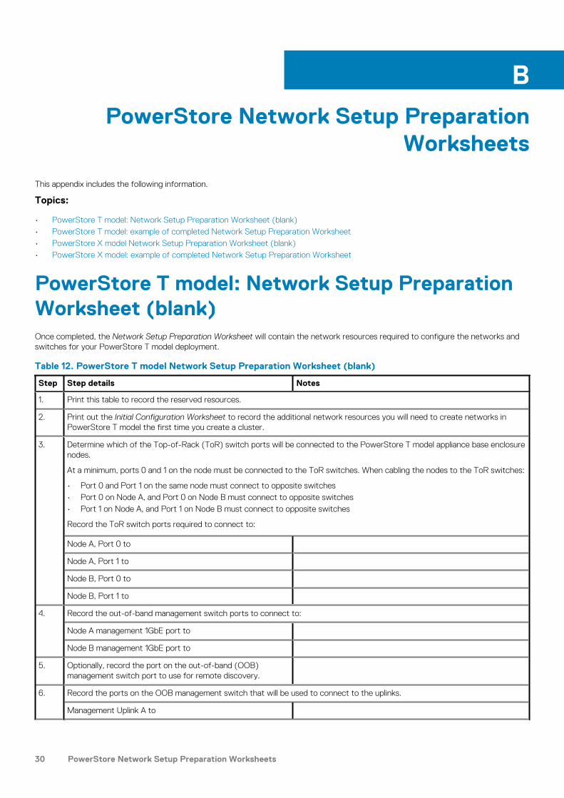
PowerStore T model: Network Setup PreparationWorksheet (blank)Once completed, the Network Setup Preparation Worksheet will contain the network resources required to configure the networks andswitches for your PowerStore T model deployment.
Table 12. PowerStore T model Network Setup Preparation Worksheet (blank)
Step Step details Notes
1. Print this table to record the reserved resources.
2. Print out the Initial Configuration Worksheet to record the additional network resources you will need to create networks inPowerStore T model the first time you create a cluster.
3. Determine which of the Top-of-Rack (ToR) switch ports will be connected to the PowerStore T model appliance base enclosurenodes.
At a minimum, ports 0 and 1 on the node must be connected to the ToR switches. When cabling the nodes to the ToR switches:
• Port 0 and Port 1 on the same node must connect to opposite switches• Port 0 on Node A, and Port 0 on Node B must connect to opposite switches• Port 1 on Node A, and Port 1 on Node B must connect to opposite switches
Record the ToR switch ports required to connect to:
Node A, Port 0 to
Node A, Port 1 to
Node B, Port 0 to
Node B, Port 1 to
4. Record the out-of-band management switch ports to connect to:
Node A management 1GbE port to
Node B management 1GbE port to
5. Optionally, record the port on the out-of-band (OOB)management switch port to use for remote discovery.
6. Record the ports on the OOB management switch that will be used to connect to the uplinks.
Management Uplink A to
B
30 PowerStore Network Setup Preparation Worksheets

Table 12. PowerStore T model Network Setup Preparation Worksheet (blank)(continued)
Step Step details Notes
Management Uplink B to
7. Record the VLAN IDs that will be used on the OOB management switch:
Remote Discovery (untagged)
Management (untagged)
8. Record the VLAN IDs that will be used on the Top-of-Rack (ToR) switches:
Storage network (tagged)
NAS (tagged)
Internal (untagged)
9. Reserve and record the IP addresses necessary to configure the switch below:
Management IP address for out-of-band management switch
Management IP address for switch 1
Management IP address for switch 2
Default gateway
NTP server
10. Dell EMC supports deploying PowerStore T model with two Top-of-Rack (ToR) switches with a layer 2 interconnect link.
Choose which type of layer 2 interconnect you will use:
Highly Recommended: Multi-chassis Link Aggregation Group (MC-LAG)
If you will be using MC-LAG, record the ports you will use to connect the switches together.
Switch to switch port pair 1
Switch to switch port pair 2
Alternative to MC-LAG: Reliable L2 uplinks
11. If using MC-LAG, enter the Domain ID.
12. If using VLT for the Layer 2 interconnect, record the:
VLT MAC address to use for both switch 1 and switch 2.
Use the same VLT MAC address for switch 1 and switch 2.
NOTE: You cannot use all zeros (00:00:00:00:00)
for the VLT MAC address.
VLT priority for switch 1
VLT priority for switch 2
13. If configuring with Link Aggregation Control Protocol (LACP) record the LACP (port channel) ID for the node connections:
Port Channel ID for Node A
Port Channel ID for Node B
14. Record the ports on the ToR switches that will be used to connect to the uplinks.
Uplink A to ToR 1
Uplink B to ToR 1
Uplink A to ToR 2
PowerStore Network Setup Preparation Worksheets 31

Table 12. PowerStore T model Network Setup Preparation Worksheet (blank)(continued)
Step Step details Notes
Uplink B to ToR 2
15. Record the port channel ID used for connectivity between the ToR switches and the uplinks.
If deploying with MC-LAG, enter the port channel ID used forthe uplink.
Only a single port channel ID is required for MC-LAG.
Alternatively, record the uplink port channel IDs required for Reliable L2.
Reliable L2 connectivity requires two port channel IDs.
1. Port channel ID for Reliable L2
2. Port channel ID for Reliable L2
16. As a best practice it is recommended to add a spanning tree protocol to the ToR switches. Record the spanning tree protocolsto set on each switch.
Spanning tree protocol for ToR switch 1
Spanning tree protocol for ToR switch 2
17. Once you have completed steps above, you have the necessary information to configure the switches. Continue to work withyour network administrator to complete the Initial Configuration Worksheet now to ensure that:
• Your network configuration on the switch aligns with the network configuration that will be done in PowerStore T model.• You reserve the necessary network resources to complete deployment of PowerStore T model and the PowerStore T model
networks.
18. Determine if you will use a direct connection or a remote connection to discover your PowerStore.
Once you have successfully discovered your PowerStore, you will be guided through the Initial Configuration Wizard tocreate your first PowerStore cluster.
PowerStore T model: example of completedNetwork Setup Preparation WorksheetThe examples of the network resources listed below are used in the deployment steps described in the PowerStore NetworkConfiguration Guide for Dell PowerSwitch Series.
Table 13. PowerStore T model Network Setup Preparation Worksheet (example)
Step Step details Notes
1. Print this table to record the reserved resources.
2. Print out the Initial Configuration Worksheet to record the additional network resources you will need to create networks inPowerStore T model the first time you create a cluster.
3. Determine which of the Top-of-Rack (ToR) switch ports will be connected to the PowerStore T model appliance base enclosurenodes.
At a minimum, ports 0 and 1 on the node must be connected to the ToR switches. When cabling the nodes to the ToR switches:
• Port 0 and Port 1 on the same node must connect to opposite switches• Port 0 on Node A, and Port 0 on Node B must connect to opposite switches• Port 1 on Node A, and Port 1 on Node B must connect to opposite switches
Record the ToR switch ports required to connect to:
Node A, Port 0 to ToR 1 port 1
Node A, Port 1 to ToR 2 port 1
32 PowerStore Network Setup Preparation Worksheets

Table 13. PowerStore T model Network Setup Preparation Worksheet (example)(continued)
Step Step details Notes
Node B, Port 0 to ToR 2 port 54
Node B, Port 1 to ToR 1 port 54
4. Record the out-of-band management switch ports to connect to:
Node A management 1GbE port to OOB port 2
Node B management 1GbE port to OOB port 53
5. Optionally, record the port on the out-of-band (OOB)management switch port to use for remote discovery.
OOB port 1
6. Record the ports on the OOB management switch that will be used to connect to the uplinks.
Management Uplink A to port 25
Management Uplink B to port 26
7. Record the VLAN IDs that will be used on the OOB management switch:
Remote Discovery (untagged) 100
Management (untagged) 100
8. Record the VLAN IDs that will be used on the Top-of-Rack (ToR) switches:
Storage network (tagged) 200
NAS (tagged) 300
Internal (untagged) 1
9. Reserve and record the IP addresses necessary to configure the switch below:
Management IP address for out-of-band management switch 100.0.100.50/24
Management IP address for switch 1 100.0.100.10/24
Management IP address for switch 2 100.0.100.11/24
Default gateway 100.0.100.1
NTP server 100.0.100.200
10. Dell EMC supports deploying PowerStore T model with two Top-of-Rack (ToR) switches with a layer 2 interconnect link.
Choose which type of layer 2 interconnect you will use:
Highly Recommended: Multi-chassis Link Aggregation Group (MC-LAG)
If you will be using MC-LAG, record the ports you will use to connect the switches together.
Switch to switch port pair 1 25 to 25
Switch to switch port pair 2 26 to 26
Alternative to MC-LAG: Reliable L2 uplinks N/A
11. If using MC-LAG, enter the Domain ID. VLT domain ID 1
12. If using VLT for the Layer 2 interconnect, record the:
VLT MAC address to use for both switch 1 and switch 2.
Use the same VLT MAC address for switch 1 and switch 2.
NOTE: You cannot use all zeros (00:00:00:00:00)
for the VLT MAC address.
00:00:00:00:00:01
VLT priority for switch 1 1
PowerStore Network Setup Preparation Worksheets 33

Table 13. PowerStore T model Network Setup Preparation Worksheet (example)(continued)
Step Step details Notes
VLT priority for switch 2 8192
13. If configuring with Link Aggregation Control Protocol (LACP) record the LACP (port channel) ID for the node connections:
Port Channel ID for Node A port channel 10
Port Channel ID for Node B port channel 20
14. Record the ports on the ToR switches that will be used to connect to the uplinks.
Uplink A to ToR 1 port 29
Uplink B to ToR 1 port 30
Uplink A to ToR 2 port 29
Uplink B to ToR 2 port 30
15. Record the port channel ID using for connectivity between the ToR switches and the uplinks.
If deploying with MC-LAG, enter the port channel ID used forthe uplink.
Only a single port channel ID is required for MC-LAG.
port channel 30
Alternatively, record the uplink port channel IDs required for Reliable L2.
Reliable L2 connectivity requires two port channel IDs.
1. Port channel ID for Reliable L2 N/A
2. Port channel ID for Reliable L2 N/A
16. As a best practice it is recommended to add a spanning tree protocol to the ToR switches. Record the spanning tree protocolsto set on each switch.
Spanning tree protocol for ToR switch 1 4096
Spanning tree protocol for ToR switch 2 8192
17 Record the port channel ID for the OOB management switch. port channel 10
18. Once you have completed steps above, you have the necessary information to configure the switches. Continue to work withyour network administrator to complete the Initial Configuration Worksheet now to ensure that:
• Your network configuration on the switch aligns with the network configuration that will be done in PowerStore T model.• You reserve the necessary network resources to complete deployment of PowerStore T model and the PowerStore T model
networks.
19. Determine if you will use a direct connection or a remote connection to discover your PowerStore.
Once you have successfully discovered your PowerStore, you will be guided through the Initial Configuration Wizard tocreate your first PowerStore cluster.
PowerStore X model Network Setup PreparationWorksheet (blank)Once completed, the Network Setup Preparation Worksheet will contain the network resources required to configure the networks andswitches for your PowerStore X model deployment.
Table 14. PowerStore X model Network Setup Preparation Worksheet (blank)
Step Step details Notes
1. Print this table to record the reserved resources.
34 PowerStore Network Setup Preparation Worksheets

Table 14. PowerStore X model Network Setup Preparation Worksheet (blank)(continued)
Step Step details Notes
2. Print out the Initial Configuration Worksheet to record the additional network resources you will need to create networks inPowerStore X model the first time you create a cluster.
3. Determine which of the Top-of-Rack (ToR) switch ports will be connected to the PowerStore X model appliance base enclosurenodes.
At a minimum, ports 0 and 1 on the node must be connected to the ToR switches. When cabling the nodes to the ToR switches:
• Port 0 and Port 1 on the same node must connect to opposite switches• Port 0 on Node A, and Port 0 on Node B must connect to opposite switches• Port 1 on Node A, and Port 1 on Node B must connect to opposite switches
Record the ToR switch ports required to connect to:
Node A, Port 0 to
Node A, Port 1 to
Node B, Port 0 to
Node B, Port 1 to
4. Record the switch port to use for discovery while configuringyour switches.
5. Record the VLAN IDs that will be used for system management:
Remote Discovery (untagged)
Management (tagged)
6. Record the VLAN IDs that will be used for production:
Storage network (tagged)
vMotion (tagged)
Internal (untagged)
7. Reserve and record the IP addresses necessary to configure the switch below:
Management IP address for switch 1
Management IP address for switch 2
Default gateway
NTP server
8. Dell EMC supports deploying PowerStore X model with two Top-of-Rack (ToR) switches with a layer 2 interconnect link.
Choose which type of layer 2 interconnect you will use:
Highly Recommended: Multi-chassis Link Aggregation Group (MC-LAG)
If you will be using MC-LAG, record the ports you will use to connect the switches together.
Switch to switch port pair 1
Switch to switch port pair 2
Alternative to MC-LAG: Reliable L2 uplinks
9. If using MC-LAG, enter the Domain ID.
10 If using VLT for the Layer 2 interconnect, record the:
VLT MAC address to use for both switch 1 and switch 2.
Use the same VLT MAC address for switch 1 and switch 2.
PowerStore Network Setup Preparation Worksheets 35

Table 14. PowerStore X model Network Setup Preparation Worksheet (blank)(continued)
Step Step details Notes
NOTE: You cannot use all zeros (00:00:00:00:00)
for the VLT MAC address.
VLT priority for switch 1
VLT priority for switch 2
11. Record the ports on the ToR switches that will be used to connect to the uplinks.
Uplink A to ToR 1
Uplink B to ToR 1
Uplink A to ToR 2
Uplink B to ToR 2
12. Record the port channel ID using for connectivity between the ToR switches, and the uplinks.
If deploying with MC-LAG, enter the port channel ID for theuplink.
Only a single port channel ID is required for MC-LAG.
Alternatively, record the uplink port channel IDs required for Reliable L2.
Reliable L2 connectivity requires two port channel IDs.
1. Port channel ID for Reliable L2
2. Port channel ID for Reliable L2
13. As a best practice it is recommended to add a spanning tree protocol to the ToR switches. Record the spanning tree protocolsto set on each switch.
Spanning tree protocol for ToR switch 1
Spanning tree protocol for ToR switch 2
14. Once you have completed steps above, you have the necessary information to configure the switches. Continue to work withyour network administrator to complete the Initial Configuration Worksheet now to ensure that:
• Your network configuration on the switch aligns with the network configuration that will be done in PowerStore X model.• You reserve the necessary network resources to complete deployment of PowerStore X model networks.
15. Determine if you will use a direct connection or a remote connection to discover your PowerStore.
Once you have successfully discovered your PowerStore, you will be guided through the Initial Configuration Wizard tocreate your first PowerStore cluster.
PowerStore X model: example of completedNetwork Setup Preparation WorksheetThe examples of the network resources listed below are used in the deployment steps described in the PowerStore NetworkConfiguration Guide for Dell PowerSwitch Series.
Table 15. PowerStore X model Network Setup Preparation Worksheet completed example
Step Step details Notes
1. Print this table to record the reserved resources.
2. Print out the Initial Configuration Worksheet to record the additional network resources you will need to create networks inPowerStore X model the first time you create a cluster.
36 PowerStore Network Setup Preparation Worksheets

Table 15. PowerStore X model Network Setup Preparation Worksheet completed example(continued)
Step Step details Notes
3. Determine which of the Top-of-Rack (ToR) switch ports will be connected to the PowerStore X model appliance base enclosurenodes.
At a minimum, ports 0 and 1 on the node must be connected to the ToR switches. When cabling the nodes to the ToR switches:
• Port 0 and Port 1 on the same node must connect to opposite switches• Port 0 on Node A, and Port 0 on Node B must connect to opposite switches• Port 1 on Node A, and Port 1 on Node B must connect to opposite switches
Record the ToR switch ports required to connect to:
Node A, Port 0 to ToR 1 port 1
Node A, Port 1 to ToR 2 port 1
Node B, Port 0 to ToR 2 port 54
Node B, Port 1 to ToR 1 port 54
4. Record the switch port to use for discovery while configuringyour switches.
port 13
5. Record the VLAN IDs that will be used for system management:
Remote Discovery (untagged) 1
Management (tagged) 100
6. Record the VLAN IDs that will be used for production:
Storage network (tagged) 200
vMotion (tagged) 400
Internal (untagged) 1
7. Reserve and record the IP addresses necessary to configure the switch below:
Management IP address for switch 1 100.0.100.10/24
Management IP address for switch 2 100.0.100.11/24
Default gateway 100.0.100.1
NTP server 100.0.100.200
8. Dell EMC supports deploying PowerStore X model with two Top-of-Rack (ToR) switches with a layer 2 interconnect link.
Choose which type of layer 2 interconnect you will use:
Highly Recommended: Multi-chassis Link Aggregation Group (MC-LAG)
If you will be using MC-LAG, record the ports you will use to connect the switches together.
Switch to switch port pair 1 25 to 25
Switch to switch port pair 2 26 to 26
Alternative to MC-LAG: Reliable L2 uplinks N/A
9. If using MC-LAG, enter the Domain ID. VLT domain ID 1
10 If using VLT for the Layer 2 interconnect, record the:
VLT MAC address to use for both switch 1 and switch 2.
Use the same VLT MAC address for switch 1 and switch 2.
NOTE: You cannot use all zeros (00:00:00:00:00)
for the VLT MAC address.
00:00:00:00:00:01
PowerStore Network Setup Preparation Worksheets 37

Table 15. PowerStore X model Network Setup Preparation Worksheet completed example(continued)
Step Step details Notes
VLT priority for switch 1 1
VLT priority for switch 2 8192
11. Record the ports on the ToR switches that will be used to connect to the uplinks.
Uplink A to ToR 1 port 29
Uplink B to ToR 1 port 30
Uplink A to ToR 2 port 29
Uplink B to ToR 2 port 30
12. Record the port channel ID using for connectivity between the ToR switches, and the uplinks.
If deploying with MC-LAG, enter the port channel ID for theuplink.
Only a single port channel ID is required for MC-LAG.
port channel 30
Alternatively, record the uplink port channel IDs required for Reliable L2.
Reliable L2 connectivity requires two port channel IDs.
1. Port channel ID for Reliable L2 N/A
2. Port channel ID for Reliable L2 N/A
13. As a best practice it is recommended to add a spanning tree protocol to the ToR switches. Record the spanning tree protocolsto set on each switch.
Spanning tree protocol for ToR switch 1 4096
Spanning tree protocol for ToR switch 2 8192
14. Once you have completed steps above, you have the necessary information to configure the switches. Continue to work withyour network administrator to complete the Initial Configuration Worksheet now to ensure that:
• Your network configuration on the switch aligns with the network configuration that will be done in PowerStore X model.• You reserve the necessary network resources to complete deployment of PowerStore X model networks.
15. Determine if you will use a direct connection or a remote connection to discover your PowerStore.
Once you have successfully discovered your PowerStore, you will be guided through the Initial Configuration Wizard tocreate your first PowerStore cluster.
38 PowerStore Network Setup Preparation Worksheets
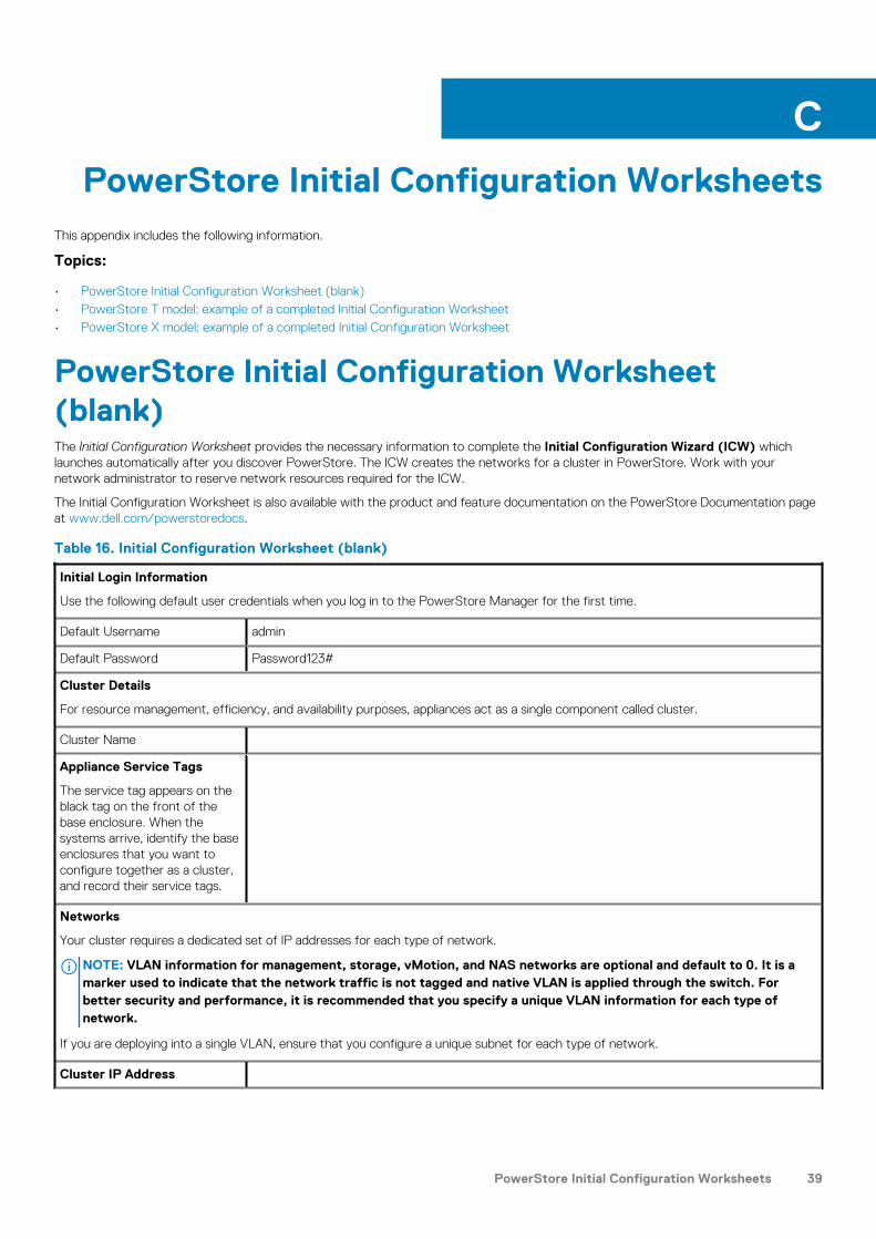
PowerStore Initial Configuration WorksheetsThis appendix includes the following information.
Topics:
• PowerStore Initial Configuration Worksheet (blank)• PowerStore T model: example of a completed Initial Configuration Worksheet• PowerStore X model: example of a completed Initial Configuration Worksheet
PowerStore Initial Configuration Worksheet(blank)The Initial Configuration Worksheet provides the necessary information to complete the Initial Configuration Wizard (ICW) whichlaunches automatically after you discover PowerStore. The ICW creates the networks for a cluster in PowerStore. Work with yournetwork administrator to reserve network resources required for the ICW.
The Initial Configuration Worksheet is also available with the product and feature documentation on the PowerStore Documentation pageat www.dell.com/powerstoredocs.
Table 16. Initial Configuration Worksheet (blank)
Initial Login Information
Use the following default user credentials when you log in to the PowerStore Manager for the first time.
Default Username admin
Default Password Password123#
Cluster Details
For resource management, efficiency, and availability purposes, appliances act as a single component called cluster.
Cluster Name
Appliance Service Tags
The service tag appears on theblack tag on the front of thebase enclosure. When thesystems arrive, identify the baseenclosures that you want toconfigure together as a cluster,and record their service tags.
Networks
Your cluster requires a dedicated set of IP addresses for each type of network.
NOTE: VLAN information for management, storage, vMotion, and NAS networks are optional and default to 0. It is amarker used to indicate that the network traffic is not tagged and native VLAN is applied through the switch. Forbetter security and performance, it is recommended that you specify a unique VLAN information for each type ofnetwork.
If you are deploying into a single VLAN, ensure that you configure a unique subnet for each type of network.
Cluster IP Address
C
PowerStore Initial Configuration Worksheets 39

Table 16. Initial Configuration Worksheet (blank)(continued)
Management Network
Connects the cluster to services such as DNS and NTP. The IP addresses in the managementnetwork are used to address the cluster, appliances, controllers, and internal hosts.
3 IPs for each PowerStore Tmodel Appliance
5 IPs for each PowerStore Xmodel Appliance
VLAN
(Optional, Defaults to 0)
Netmask/Prefix Length Gateway IP Addresses
Storage Network (Optional)
Enables clients to access the storage in the cluster. The IP addresses in the storage network are usedfor iSCSI targets, iSCSI initiators, and the Global Storage Discovery IP address. If you want to enableiSCSI interfaces later or only use Fibre Channel, you can skip this step.
NOTE: At a minimum, you need 6 IP addresses for each PowerStore X model appliance.However, for performance improvements, it is highly recommended that you have 10 IPaddresses for each PowerStore X model appliance.
2 IPs for each PowerStore Tmodel Appliance
6 or 10 IPs for eachPowerStore X modelAppliance
VLAN
(Optional, Defaults to 0)
Netmask/Prefix Length Gateway IP Addresses
Global Storage Discovery IP Address
The last IP address you specify here is used as the Global Storage Discovery IP address. It isrecommended that you choose to create this IP address. It is used as the single highly availablefloating IP address for hosts to easily discover storage from your cluster.
vMotion Network
Enables users to migrate virtual machines within the vSphere cluster. The IP addresses in the vMotionnetwork are used for a dedicated network that transfer virtual machines between appliances.
2 IPs for each PowerStore Xmodel Appliance
VLAN
(Optional, Defaults to 0)
Netmask/Prefix Length Gateway IP Addresses
Infrastructure Services
Record IP addresses for your DNS and NTP servers. It is recommended that you specify at least two addresses for DNS and NTPservers each.
DNS Server
NTP Server
Physical/Top-of-Rack Switch Information (Optional)
Record the switch IP addresses to validate the cabling and switch settings before the cluster is configured. To ensure a strong layer ofredundancy, it is required that you connect your appliance to at least two switches. You can provide read-only credentials for theswitches.
40 PowerStore Initial Configuration Worksheets

Table 16. Initial Configuration Worksheet (blank)(continued)
Protocol (SSH/SNMP)
IP Address
Port
User Credentials / Community String
PowerStore T model Only Out-of-Band Management Switch Information (Optional)
You can provide read-only credentials for the switches.
Protocol (SSH / SNMP)
IP Address
Port
User Credentials /Community String
PowerStore X model Only Hypervisor
Record your existing vCenter administrator login credentials. The initial configuration workflowautomatically creates a datacenter and ESXi cluster, and associates them with your cluster.
NOTE: Ensure that the vCenter Server is accessible on the network.
Existing vCenter IP Address
Existing vCenter UserCredentials
New Datacenter Name
New ESXi Cluster Name
SupportAssist (Optional)
SupportAssist is a secure, automated health and system monitoring capability. It sends notifications to Dell EMC, enables remotesupport, and sends data to CloudIQ. Once your cluster is created successfully, you can connect to Dell EMC SupportAssist. If youalready have SupportAssist enabled, record the associated account details and the gateway or proxy IP information here.
Tip: The default port number Dell EMC uses is 9443.
Gateway or Proxy Server IP Address
Gateway or Proxy Server Port
Proxy Server User Credentials
(Not applicable for Gateway Connect)
Policy Manager IP Address and Port
(Not applicable for Direct Connect without remote access orGateway Connect)
PowerStore T model: example of a completedInitial Configuration WorksheetThe examples of the network resources listed below are used in the deployment steps described in the PowerStore NetworkConfiguration Guide for Dell PowerSwitch Series.
Table 17. PowerStore T model: completed example of an Initial Configuration Worksheet
Initial Login Information
PowerStore Initial Configuration Worksheets 41

Table 17. PowerStore T model: completed example of an Initial Configuration Worksheet(continued)
Use the following default user credentials when you log in to the PowerStore Manager for the first time.
Default Username admin
Default Password Password123#
Cluster Details
For resource management, efficiency, and availability purposes, appliances act as a single component called cluster.
Cluster Name PowerStoreTCluster
Appliance Service Tags
The service tag appears on theblack tag on the front of thebase enclosure. When thesystems arrive, identify the baseenclosures that you want toconfigure together as a cluster,and record their service tags.
CNR42W2
Networks
Your cluster requires a dedicated set of IP addresses for each type of network.
NOTE: VLAN information for management, storage, vMotion, and NAS networks are optional and default to 0. It is amarker used to indicate that the network traffic is not tagged and native VLAN is applied through the switch. Forbetter security and performance, it is recommended that you specify VLAN information for each type of network.
Ensure that you configure a unique subnet for each type of network.
Management Network
Connects the cluster to services such as DNS and NTP. The IP addresses in the managementnetwork are used to address the cluster, appliances, controllers, and internal hosts.
4 IPs for each PowerStore Tmodel Appliance
6 IPs for each PowerStore Xmodel Appliance
Cluster IP Address 192.168.1.10
VLAN
(Optional, Defaults to 0)
Netmask/Prefix Length Gateway IP Addresses
0 255.255.255.0/24 192.168.1.1 192.168.1.11-13
Storage Network (Optional)
Enables clients to access the storage in the cluster. The IP addresses in the storage network are usedfor iSCSI targets, iSCSI initiators, and the Global Storage Discovery IP address. If you want to enableiSCSI interfaces later or only use Fibre Channel, you can skip this step.
NOTE: At a minimum, you need 6 IP addresses for each PowerStore X model appliance.However, for performance improvements, it is highly recommended that you have 10 IPaddresses for each PowerStore X model appliance.
2 IPs for each PowerStore Tmodel Appliance
6 or 10 IPs for eachPowerStore X modelAppliance
Global Storage Discovery IP Address
The last IP address you specify here is used as the Global Storage Discovery IP address. It isrecommended that you choose to create this IP address. It is used as the single highly availablefloating IP address for hosts to easily discover storage from your cluster.
192.168.2.12
VLAN
(Optional, Defaults to 0)
Netmask/Prefix Length Gateway IP Addresses
200 255.255.255.0/24 192.168.2.1 192.168.2.10-11
42 PowerStore Initial Configuration Worksheets

Table 17. PowerStore T model: completed example of an Initial Configuration Worksheet(continued)
vMotion Network
Enables users to migrate virtual machines within the vSphere cluster. The IP addresses in the vMotionnetwork are used for a dedicated network that transfer virtual machines between appliances.
2 IPs for each PowerStore Xmodel Appliance
VLAN
(Optional, Defaults to 0)
Netmask/Prefix Length Gateway IP Addresses
N/A N/A N/A N/A
Infrastructure Services
Record IP addresses for your DNS and NTP servers. It is recommended that you specify at least two addresses for DNS and NTPservers each.
DNS Server 100.0.100.200 100.0.100.201
NTP Server 100.0.100.200 100.0.100.201
Top-of-Rack (ToR) Information
Record the switch IP addresses to validate the cabling and switch settings before the cluster is configured. To ensure a strong layer ofredundancy, it is required that you connect your appliance to at least two switches. You can provide read-only credentials for theswitches.
Protocol (SSH/SNMP) SSH SSH
IP Address 100.0.100.10/24 100.0.100.11/24
Port Port 22 Port 22
User Credentials / Community String admin/Password123! admin/Password123!
PowerStore T model Only Out-of-Band Management Switch Information
You can provide read-only credentials for the switches.
Protocol (SSH / SNMP) SSH N/A
IP Address 100.0.100.50/24 N/A
Ports 22 N/A
User Credentials /Community String
admin/Password123! N/A
PowerStore X model Only Hypervisor
Record your existing vCenter administrator login credentials. The initial configuration workflowautomatically creates a datacenter and ESXi cluster, and associates them with your cluster.
NOTE: Ensure that the vCenter Server is accessible on the network.
Existing vCenter IP Address N/A
Existing vCenter UserCredentials
N/A
New Datacenter Name N/A
New ESXi Cluster Name N/A
SupportAssist (Optional)
SupportAssist is a secure, automated health and system monitoring capability. It sends notifications to Dell EMC, enables remotesupport, and sends data to CloudIQ. Once your cluster is created successfully, you can connect to Dell EMC SupportAssist. If youalready have SupportAssist enabled, record the associated account details and the gateway or proxy IP information here.
Tip: The default port number Dell EMC uses is 9443.
Gateway or Proxy Server IP Address N/A
PowerStore Initial Configuration Worksheets 43

Table 17. PowerStore T model: completed example of an Initial Configuration Worksheet(continued)
Gateway or Proxy Server Port N/A
Proxy Server User Credentials
(Not applicable for Gateway Connect)
N/A
Policy Manager IP Address and Port
(Not applicable for Direct Connect without remote access orGateway Connect)
N/A
PowerStore X model: example of a completedInitial Configuration WorksheetThe following is an example of an Initial Configuration Worksheet completed for a PowerStore T model deployment.
Table 18. PowerStore X model: completed example of an Initial Configuration Worksheet
Initial Login Information
Use the following default user credentials when you log in to the PowerStore Manager for the first time.
Default Username admin
Default Password Password123#
Cluster Details
For resource management, efficiency, and availability purposes, appliances act as a single component called cluster.
Cluster Name PowerStoreXCluster
Appliance Service Tags
The service tag appears on theblack tag on the front of thebase enclosure. When thesystems arrive, identify the baseenclosures that you want toconfigure together as a cluster,and record their service tags.
CNR42W2
Networks
Your cluster requires a dedicated set of IP addresses for each type of network.
NOTE: VLAN information for management, storage, vMotion, and NAS networks are optional and default to 0. It is amarker used to indicate that the network traffic is not tagged and native VLAN is applied through the switch. Forbetter security and performance, it is recommended that you specify a unique VLAN information for each type ofnetwork.
If you are deploying into a single VLAN, ensure that you configure a unique subnet for each type of network.
Cluster IP Address 192.168.1.10
Management Network
Connects the cluster to services such as DNS and NTP. The IP addresses in the managementnetwork are used to address the cluster, appliances, controllers, and internal hosts.
3 IPs for each PowerStore Tmodel Appliance
5 IPs for each PowerStore Xmodel Appliance
VLAN
(Optional, Defaults to 0)
Netmask/Prefix Length Gateway IP Addresses
100 255.255.255.0/24 192.168.1.1 192.168.1.11-14
44 PowerStore Initial Configuration Worksheets

Table 18. PowerStore X model: completed example of an Initial Configuration Worksheet (continued)
Storage Network (Optional)
Enables clients to access the storage in the cluster. The IP addresses in the storage network are usedfor iSCSI targets, iSCSI initiators, and the Global Storage Discovery IP address. If you want to enableiSCSI interfaces later or only use Fibre Channel, you can skip this step.
NOTE: At a minimum, you need 6 IP addresses for each PowerStore X model appliance.However, for performance improvements, it is highly recommended that you have 10 IPaddresses for each PowerStore X model appliance.
2 IPs for each PowerStore Tmodel Appliance
6 or 10 IPs for eachPowerStore X modelAppliance
VLAN
(Optional, Defaults to 0)
Netmask/Prefix Length Gateway IP Addresses
200 255.255.255.0/24 192.168.2.1 192.168.2.10-19
Global Storage Discovery IP Address
The last IP address you specify here is used as the Global Storage Discovery IP address. It isrecommended that you choose to create this IP address. It is used as the single highly availablefloating IP address for hosts to easily discover storage from your cluster.
192.168.2.20
vMotion Network
Enables users to migrate virtual machines within the vSphere cluster. The IP addresses in the vMotionnetwork are used for a dedicated network that transfer virtual machines between appliances.
2 IPs for each PowerStore Xmodel Appliance
VLAN
(Optional, Defaults to 0)
Netmask/Prefix Length Gateway IP Addresses
400 255.255.255.0/24 192.168.4.1 192.168.4.10-11
Infrastructure Services
Record IP addresses for your DNS and NTP servers. It is recommended that you specify at least two addresses for DNS and NTPservers each.
DNS Server 100.0.100.200 100.0.100.201
NTP Server 100.0.100.200 100.0.100.201
Physical/Top-of-Rack Switch Information (Optional)
Record the switch IP addresses to validate the cabling and switch settings before the cluster is configured. To ensure a strong layer ofredundancy, it is required that you connect your appliance to at least two switches. You can provide read-only credentials for theswitches.
Protocol (SSH/SNMP) SSH SSH
IP Address 100.0.100.10/24 100.0.100.11/24
Port Port 22 Port 22
User Credentials / Community String admin/Password123! admin/Password123!
PowerStore T model Only Out-of-Band Management Switch Information (Optional)
You can provide read-only credentials for the switches.
Protocol (SSH / SNMP) N/A N/A
IP Address N/A N/A
Port N/A N/A
User Credentials /Community String
N/A N/A
PowerStore Initial Configuration Worksheets 45

Table 18. PowerStore X model: completed example of an Initial Configuration Worksheet (continued)
PowerStore X model Only Hypervisor
Record your existing vCenter administrator login credentials. The initial configuration workflowautomatically creates a datacenter and ESXi cluster, and associates them with your cluster.
NOTE: Ensure that the vCenter Server is accessible on the network.
Existing vCenter IP Address 100.0.100.220
Existing vCenter UserCredentials
[email protected]/Password123!
New Datacenter Name DataCenter-PowerStoreXCluster
New ESXi Cluster Name Cluster-PowerStoreXCluster
SupportAssist (Optional)
SupportAssist is a secure, automated health and system monitoring capability. It sends notifications to Dell EMC, enables remotesupport, and sends data to CloudIQ. Once your cluster is created successfully, you can connect to Dell EMC SupportAssist. If youalready have SupportAssist enabled, record the associated account details and the gateway or proxy IP information here.
Tip: The default port number Dell EMC uses is 9443.
Gateway or Proxy Server IP Address N/A
Gateway or Proxy Server Port N/A
Proxy Server User Credentials
(Not applicable for Gateway Connect)
N/A
Policy Manager IP Address and Port
(Not applicable for Direct Connect without remote access orGateway Connect)
N/A
46 PowerStore Initial Configuration Worksheets