dell command | monitor · the dell command | monitor software enables remote management application...
TRANSCRIPT
Dell Command | MonitorVersion 10.0 Reference Guide

Notes, cautions, and warnings
NOTE: A NOTE indicates important information that helps you make better use of your product.
CAUTION: A CAUTION indicates either potential damage to hardware or loss of data and tells you how to avoid the problem.
WARNING: A WARNING indicates a potential for property damage, personal injury, or death.
© 2008 -2018 Dell Inc. or its subsidiaries. All rights reserved. Dell, EMC, and other trademarks are trademarks of Dell Inc. or its subsidiaries. Other trademarks may be trademarks of their respective owners.
2018 - 04
Rev. A00
Contents
1 Introduction....................................................................................................................................................7
2 Dell Command | Monitor Namespaces........................................................................................................... 8
3 Profiles.......................................................................................................................................................... 9
4 Classes......................................................................................................................................................... 11
5 Dell Command | Monitor classes and properties........................................................................................... 12Classes supported for systems running Linux...............................................................................................................12Classes supported for systems running Windows........................................................................................................ 12
DCIM_AlertIndication................................................................................................................................................. 13DCIM_BaseMetricDefinition..................................................................................................................................... 18DCIM_Card................................................................................................................................................................. 20DCIM_Chassis............................................................................................................................................................ 22DCIM_Chip................................................................................................................................................................. 25DCIM_DesktopMonitor.............................................................................................................................................26DCIM_DHCPProtocolEndpoint................................................................................................................................36DCIM_EthernetPort.................................................................................................................................................. 45DCIM_FlatPanel......................................................................................................................................................... 47DCIM_IPProtocolEndpoint....................................................................................................................................... 49DCIM_ControllerView................................................................................................................................................54DCIM_PhysicalDiskView...........................................................................................................................................55DCIM_VirtualDiskView.............................................................................................................................................. 56DCIM_PhysicalMemory............................................................................................................................................ 58DCIM_PhysicalPackage............................................................................................................................................60DCIM_ParallelPort..................................................................................................................................................... 62DCIM_RemoteServiceAccessPoint.........................................................................................................................66DCIM_Slot...................................................................................................................................................................70DCIM_SerialPort.........................................................................................................................................................74DCIM_USBPort..........................................................................................................................................................80DCIM_Memory...........................................................................................................................................................84DCIM_PCIDevice.......................................................................................................................................................89DCIM_DisplayController............................................................................................................................................92DCIM_Fan.................................................................................................................................................................. 95DCIM_IndicatorLED...................................................................................................................................................99DCIM_PowerSupply.................................................................................................................................................102DCIM_Battery...........................................................................................................................................................105DCIM_Processor.......................................................................................................................................................110DCIM_NumericSensor.............................................................................................................................................120DCIM_Sensor............................................................................................................................................................128DCIM_DeviceBay..................................................................................................................................................... 133DCIM_VideoHead..................................................................................................................................................... 136
Contents 3

DCIM_Button............................................................................................................................................................139DCIM_LCDPanel.......................................................................................................................................................142DCIM_NetworkPortConfigurationService............................................................................................................ 143DCIM_TimeService.................................................................................................................................................. 146DCIM_AccountManagementService..................................................................................................................... 148DCIM_RoleBasedAuthorizationService..................................................................................................................151DCIM_PowerManagementService........................................................................................................................ 153DCIM_BootService.................................................................................................................................................. 155DCIM_IPConfigurationService............................................................................................................................... 158DCIM_PowerUtilizationManagementService....................................................................................................... 159DCIM_BIOSService..................................................................................................................................................163DCIM_SoftwareInstallationService........................................................................................................................ 165DCIM_ComputerSystem......................................................................................................................................... 168DCIM_RecordLog..................................................................................................................................................... 173DCIM_OperatingSystem.......................................................................................................................................... 178DCIM_SoftwareIdentity...........................................................................................................................................182DCIM_BIOSElement................................................................................................................................................ 184DCIM_ConcreteJob................................................................................................................................................. 186DCIM_BootSourceSetting.......................................................................................................................................187DCIM_BootConfigSetting....................................................................................................................................... 188DCIM_IPAssignmentSettingData........................................................................................................................... 189DCIM_PowerAllocationSettingData.......................................................................................................................189DCIM_AssetAcquisition............................................................................................................................................191DCIM_AssetExtendedWarrantyInformation..........................................................................................................192DCIM_AssetOwnerInformation.............................................................................................................................. 193DCIM_AssetSupportInformation............................................................................................................................ 194DCIM_AssetWarrantyInformation.......................................................................................................................... 195DCIM_AssetSystemInformation............................................................................................................................. 196DCIM_AMTSettings.................................................................................................................................................196DCIM_ASFSettings.................................................................................................................................................. 197DCIM_VProSettings................................................................................................................................................. 197DCIM_AlertIndicationSettingData..........................................................................................................................199DCIM_HDDAlertIndicationSettingData.................................................................................................................204DCIM_BaseMetricValue......................................................................................................................................... 204DCIM_LogEntry.......................................................................................................................................................205DCIM_IndicatorLEDCapabilities.............................................................................................................................206DCIM_ProcessorCapabilities..................................................................................................................................207DCIM_AccountManagementCapabilities............................................................................................................. 208DCIM_BootServiceCapabilities..............................................................................................................................209DCIM_PlatformWatchdogServiceCapabilities..................................................................................................... 209DCIM_DHCPCapabilities..........................................................................................................................................211DCIM_PowerUtilizationManagementCapabilities................................................................................................. 211DCIM_EnabledLogicalElementCapabilities............................................................................................................212DCIM_ButtonCapabilities........................................................................................................................................ 213DCIM_LCDPanelCapabilities...................................................................................................................................214DCIM_PowerManagementCapabilities..................................................................................................................214DCIM_PhysicalAssetCapabilities............................................................................................................................ 216
4 Contents

DCIM_RoleBasedManagementCapabilities...........................................................................................................216DCIM_AllocationCapabilities................................................................................................................................... 217DCIM_BIOSServiceCapabilities.............................................................................................................................. 218DCIM_SoftwareInstallationServiceCapabilities.....................................................................................................219DCIM_ConcreteCollection......................................................................................................................................220DCIM_RedundancySet............................................................................................................................................ 221DCIM_Role............................................................................................................................................................... 222DCIM_IndicationSettingCollection.........................................................................................................................223DCIM_ConfigurationCapacity.................................................................................................................................224DCIM_Location........................................................................................................................................................225DCIM_BIOSEnumeration........................................................................................................................................226DCIM_BIOSPassword............................................................................................................................................. 227DCIM_BIOSString................................................................................................................................................... 228DCIM_MemoryError................................................................................................................................................229DCIM_IdentityContext............................................................................................................................................230DCIM_OrderedComponent.................................................................................................................................... 230DCIM_Container...................................................................................................................................................... 230DCIM_ConcreteComponent....................................................................................................................................231DCIM_SystemDevice............................................................................................................................................... 231DCIM_AccountOnSystem.......................................................................................................................................231DCIM_InstalledOS.................................................................................................................................................... 231DCIM_SystemBIOS.................................................................................................................................................. 231DCIM_SystemComponent......................................................................................................................................232DCIM_SettingsDefineCapabilities..........................................................................................................................232DCIM_DeviceSAPImplementation.........................................................................................................................233DCIM_HostedAccessPoint.....................................................................................................................................233DCIM_HostedCollection......................................................................................................................................... 233DCIM_HostedService............................................................................................................................................. 234DCIM_VideoHeadOnController.............................................................................................................................. 234DCIM_SAPSAPDependency.................................................................................................................................. 234DCIM_ReferencedProfile........................................................................................................................................234DCIM_MetricDefForME......................................................................................................................................... 234DCIM_MetricForME................................................................................................................................................235DCIM_MetricInstance.............................................................................................................................................235DCIM_ElementInConnector................................................................................................................................... 235DCIM_Docked..........................................................................................................................................................235DCIM_ConcreteDependency................................................................................................................................. 236DCIM_Realizes.........................................................................................................................................................236DCIM_ComputerSystemPackage..........................................................................................................................236DCIM_RunningOS................................................................................................................................................... 236DCIM_UseOfLog......................................................................................................................................................236DCIM_AssociatedIndicatorLED..............................................................................................................................237DCIM_AssociatedCacheMemory...........................................................................................................................237DCIM_AssociatedSensor........................................................................................................................................238DCIM_RemoteAccessAvailableToElement........................................................................................................... 238DCIM_ServiceServiceDependency....................................................................................................................... 238DCIM_DeviceConnection....................................................................................................................................... 239
Contents 5

DCIM_ElementSoftwareIdentity............................................................................................................................239DCIM_ElementCapabilities.....................................................................................................................................239DCIM_ElementSettingData....................................................................................................................................239DCIM_OrderedMemberOfCollection......................................................................................................................241DCIM_MemberOfCollection...................................................................................................................................242DCIM_OwningCollectionElement.......................................................................................................................... 242DCIM_ElementConformsToProfile........................................................................................................................ 242DCIM_RoleLimitedToTarget....................................................................................................................................242DCIM_ElementCapacity......................................................................................................................................... 243DCIM_ServiceAffectsElement................................................................................................................................243DCIM_AssociatedPowerManagementService.....................................................................................................244DCIM_ServiceAvailableToElement.........................................................................................................................245DCIM_LogManagesRecord.................................................................................................................................... 245DCIM_InstalledSoftwareIdentity............................................................................................................................246DCIM_ConcreteIdentity.......................................................................................................................................... 246DCIM_SettingsDefineState.................................................................................................................................... 246DCIM_ElementLocation..........................................................................................................................................246DCIM_CredentialContext........................................................................................................................................246DCIM_OwningJobElement..................................................................................................................................... 247
6 BIOS settings supported in Dell Command | Monitor................................................................................. 248
7 Alerts in Dell Command | Monitor ............................................................................................................. 309
8 Sample scripts............................................................................................................................................312
6 Contents

IntroductionThe Dell Command | Monitor software enables remote management application programs to access information, monitor the status, or change the state of the system, such as shutting it down remotely. Dell Command | Monitor exposes, through standard interfaces, key system parameters that allow administrators to manage, inventory, monitor the system health of, and gather information on deployed client systems. Dell Command | Monitor is designed for Dell Enterprise client systems, Dell IoT Gateway systems, as well as for Dell Embedded PCs. For more information on supported Dell systems refer Release notes available at dell.com/dellclientcommandsuitemanuals.
NOTE: Dell Command | Monitor was formerly Dell OpenManage Client Instrumentation (OMCI). After the OMCI version 8.2.1, OMCI is rebranded as Dell Command | Monitor.
NOTE: All classes or properties listed in the reference guide may not be supported on all Dell systems.
1
Introduction 7

Dell Command | Monitor NamespacesNamespaces are standards-based with implementation of multiple profiles as defined by the Distributed Management Task Force (DMTF). The following namespaces are available in Dell Command | Monitor:
• root\dcim\sysman - The CIM schema for this namespace is 2.17 and provides all the functionality of Dell Command | Monitor for Windows. Dell Command | Monitor for Windows, usees DASH-compliant namespace conventions. A DASH-compliant implementation uses a CIM-based data model for representing managed resources and services.
• root/dcim/sysman - The CIM schema for this namespace is 2.32.0 and provides all the functionality of Dell Command | Monitor for Linux.
2
8 Dell Command | Monitor Namespaces

ProfilesDell Command | Monitor running on Microsoft Windows operating system uses industry standard profiles to represent the management data provided. These profiles are implemented either as defined or in some cases have Dell-specific extensions.
The following is a list of profiles that are implemented for Dell Command | Monitor for Windows:
Non-extended profiles:
• Base Metrics — The Base Metrics Profile is a component profile that defines the minimum object model needed to provide dynamic metrics associated to existing managed element s and related associations.
• Battery — The Battery Profile extends the management capabilities of referencing profiles by adding the capability to represent batteries for manageability. The battery as a logical device is modeled as referencing the battery physical package for physical asset information, the sensor for sensor-reading information, and the profile registration for the schema implementation version information.
• BIOS Management — The BIOS Management Profile extends the management capabilities of referencing profiles by adding the capability to represent and configure BIOS settings, such as a Network Controller or IDE Controller. The individual BIOS settings’ relationship with a respective device is also described.
• Boot Control — The Boot Control Profile describes the classes, associations, properties, and methods used to manage the boot control configurations of a physical or virtual computer system.
• CPU — The CPU Profile extends the management capability of referencing profiles by adding the capability to represent CPUs or processors in a managed system . CPU cache memory and associations with CPU physical aspects, as well as profile implementation version information, are modeled in this profile.
• Fan — The Fan Profile extends the management capabilities of referencing profiles by adding the capability to represent fans for manageability and describe fans in a redundant configuration. The fan as a logical device is modeled as referencing the fan physical package for physical asset information, a sensor for sensor reading information.
• Indications — The Indications Profile defines the CIM elements that are used to subscribe for indications of unsolicited events, to advertise the possible indications, and to represent indications used to report events in a managed system.
• IP Interface — The IP Interface Profile extends the management capability of referencing profiles by adding the capability to represent an IP interface of a managed system.
• OS Status — The OS Status Profile extends the management capabilities of referencing profiles by adding the capability to perform basic management of operating systems installed on a system.
• PCI Device — The PCI Device Profile extends the management capabilities of referencing profiles by adding the capability to represent PCI devices for manageability, including PCI, PCI-X, PCI Express, bridge and switch devices.
• Physical Asset — The Physical Asset Profile extends the management capability of the referencing profiles by adding the capability to describe the physical aspects of logical elements that the implementation is instantiating.
• Power State Management — The Power State Management Profile describes the classes, associations, properties, and methods used to manage the power of a computer system.
• Profile Registration — The Profile Registration extends the management capability of the referencing profiles by adding the capability to describe the registration and versioning of CIM profiles that are implemented by CIM based system and component management instrumentations.
• RecordLog — The Record Log Profile is an autonomous profile that provides the management capabilities to represent logs of a managed system element.
• Sensors — The Sensors Profile extends the management capabilities of referencing profiles by adding the capability to represent sensors.
• Software Inventory — The Software Inventory Profile describes the CIM schema elements required to provide an inventory of installed BIOS, firmware, drivers, and related software in a managed system.
• Device Tray — The Device Tray Profile is a component profile for modeling a device tray of a modular system.
• Software Update — The Software Update Profile describes the classes, associations, properties, and methods used to support the installation and update of BIOS, firmware, drivers and related software on a managed element within a managed system.
• Base Desktop and Mobile — The Base Desktop and Mobile Profile is an autonomous profile that defines the classes used to describe monolithic desktop or mobile computer hardware and related software. The scope of this profile is limited to monolithic desktop or mobile computer hardware and related software that are directly realized in physical components.
3
Profiles 9
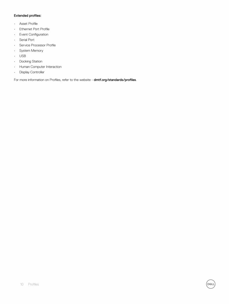
Extended profiles:
• Asset Profile
• Ethernet Port Profile
• Event Configuration
• Serial Port
• Service Processor Profile
• System Memory
• USB
• Docking Station
• Human Computer Interaction
• Display Controller
For more information on Profiles, refer to the website - dmtf.org/standards/profiles.
10 Profiles

ClassesClasses and properties are defined by the CIM schema. The profiles identify mandatory classes and properties in order to implement the profile.
For more information on CIM schema, classes and properties, refer to the website - dmtf.org/standards/cim
4
Classes 11
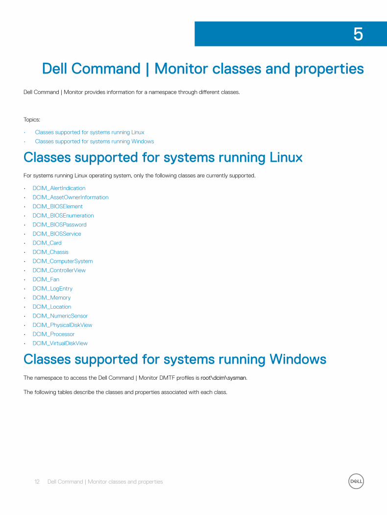
Dell Command | Monitor classes and propertiesDell Command | Monitor provides information for a namespace through different classes.
Topics:
• Classes supported for systems running Linux
• Classes supported for systems running Windows
Classes supported for systems running LinuxFor systems running Linux operating system, only the following classes are currently supported.
• DCIM_AlertIndication
• DCIM_AssetOwnerInformation
• DCIM_BIOSElement
• DCIM_BIOSEnumeration
• DCIM_BIOSPassword
• DCIM_BIOSService
• DCIM_Card
• DCIM_Chassis
• DCIM_ComputerSystem
• DCIM_ControllerView
• DCIM_Fan
• DCIM_LogEntry
• DCIM_Memory
• DCIM_Location
• DCIM_NumericSensor
• DCIM_PhysicalDiskView
• DCIM_Processor
• DCIM_VirtualDiskView
Classes supported for systems running WindowsThe namespace to access the Dell Command | Monitor DMTF profiles is root\dcim\sysman.
The following tables describe the classes and properties associated with each class.
5
12 Dell Command | Monitor classes and properties
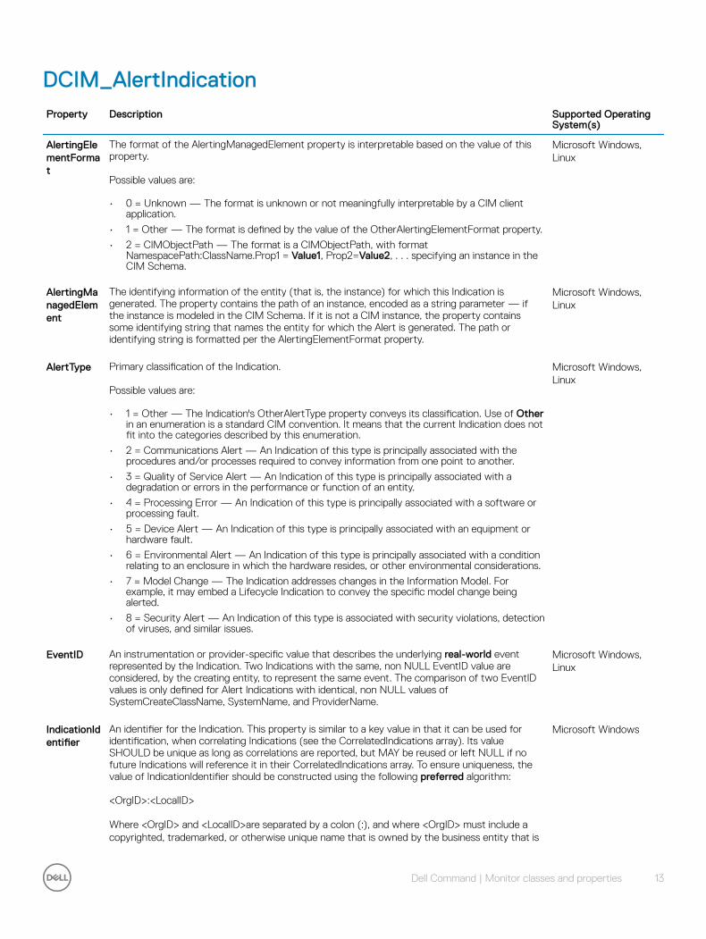
DCIM_AlertIndicationProperty Description Supported Operating
System(s)
AlertingElementFormat
The format of the AlertingManagedElement property is interpretable based on the value of this property.
Possible values are:
• 0 = Unknown — The format is unknown or not meaningfully interpretable by a CIM client application.
• 1 = Other — The format is defined by the value of the OtherAlertingElementFormat property.
• 2 = CIMObjectPath — The format is a CIMObjectPath, with format NamespacePath:ClassName.Prop1 = Value1, Prop2=Value2, . . . specifying an instance in the CIM Schema.
Microsoft Windows, Linux
AlertingManagedElement
The identifying information of the entity (that is, the instance) for which this Indication is generated. The property contains the path of an instance, encoded as a string parameter — if the instance is modeled in the CIM Schema. If it is not a CIM instance, the property contains some identifying string that names the entity for which the Alert is generated. The path or identifying string is formatted per the AlertingElementFormat property.
Microsoft Windows, Linux
AlertType Primary classification of the Indication.
Possible values are:
• 1 = Other — The Indication's OtherAlertType property conveys its classification. Use of Other in an enumeration is a standard CIM convention. It means that the current Indication does not fit into the categories described by this enumeration.
• 2 = Communications Alert — An Indication of this type is principally associated with the procedures and/or processes required to convey information from one point to another.
• 3 = Quality of Service Alert — An Indication of this type is principally associated with a degradation or errors in the performance or function of an entity.
• 4 = Processing Error — An Indication of this type is principally associated with a software or processing fault.
• 5 = Device Alert — An Indication of this type is principally associated with an equipment or hardware fault.
• 6 = Environmental Alert — An Indication of this type is principally associated with a condition relating to an enclosure in which the hardware resides, or other environmental considerations.
• 7 = Model Change — The Indication addresses changes in the Information Model. For example, it may embed a Lifecycle Indication to convey the specific model change being alerted.
• 8 = Security Alert — An Indication of this type is associated with security violations, detection of viruses, and similar issues.
Microsoft Windows, Linux
EventID An instrumentation or provider-specific value that describes the underlying real-world event represented by the Indication. Two Indications with the same, non NULL EventID value are considered, by the creating entity, to represent the same event. The comparison of two EventID values is only defined for Alert Indications with identical, non NULL values of SystemCreateClassName, SystemName, and ProviderName.
Microsoft Windows, Linux
IndicationIdentifier
An identifier for the Indication. This property is similar to a key value in that it can be used for identification, when correlating Indications (see the CorrelatedIndications array). Its value SHOULD be unique as long as correlations are reported, but MAY be reused or left NULL if no future Indications will reference it in their CorrelatedIndications array. To ensure uniqueness, the value of IndicationIdentifier should be constructed using the following preferred algorithm:
<OrgID>:<LocalID>
Where <OrgID> and <LocalID>are separated by a colon (:), and where <OrgID> must include a copyrighted, trademarked, or otherwise unique name that is owned by the business entity that is
Microsoft Windows
Dell Command | Monitor classes and properties 13

Property Description Supported Operating System(s)
creating or defining the IndicationIdentifier or that is a recognized ID that is assigned to the business entity by a recognized global authority. (This requirement is similar to the <Schema Name>_<Class Name> structure of Schema class names.) In addition, to ensure uniqueness must not contain a colon (:). When using this algorithm, the first colon to appear in IndicationIdentifier must appear between <OrgID>and <LocalID> is chosen by the business entity and should not be re-used to identify different underlying (real-world) elements. If the above preferred algorithm is not used, the defining entity should assure that the resulting IndicationIdentifier is not reused across any IndicationIdentifiers that are produced by this or other providers for the NameSpace of this instance.
IndicationTime
The time and date of creation of the Indication. The property may be set to NULL if the entity creating the Indication is not capable of determining this information.
NOTE: IndicationTime may be the same for two Indications that are generated in rapid succession.
Microsoft Windows
Message The formatted message. This message is constructed by combining some or all of the dynamic elements specified in the MessageArguments property with the static elements uniquely identified by the MessageID in a message registry or other catalog associated with the OwningEntity.
Microsoft Windows
MessageArguments
An array containing the dynamic content of the message. Microsoft Windows, Linux
MessageID A string that uniquely identifies, within the scope of the OwningEntity, the format of the Message.
Microsoft Windows
OtherAlertingElementFormat
A string defining Other values for AlertingElementFormat. This value MUST be set to a non NULL value when AlertingElementFormat is set to a value of 1 (Other). For all other values of AlertingElementFormat, the value of this string must be set to NULL.
Microsoft Windows, Linux
OtherAlertType
A string describing the Alert type — used when the AlertType property is set to 1, Other State Change.
Microsoft Windows, Linux
OtherSeverity
Holds the value of the user-defined severity value when PerceivedSeverity is 1 (Other). Microsoft Windows, Linux
OwningEntity
A string that uniquely identifies the entity that owns the definition of the format of the Message described in this instance. OwningEntity MUST include a copyrighted, trademarked or otherwise unique name that is owned by the business entity or standards body defining the format.
Microsoft Windows, Linux
PerceivedSeverity
An enumerated value that describes the severity of the Alert Indication from the notifier's point of view:
Possible values are:
• 2 and 0 — Information and Unknown (respectively) follow common usage. Literally, the AlertIndication is purely informational or its severity is unknown.
• 1 = Other — By CIM convention, is used to indicate that the Severity's value can be found in the OtherSeverity property.
• 3 = Degraded/Warning — Is used when it is appropriate to let the user decide if action is needed.
• 4 = Minor — Is used to indicate that action is needed, but the situation is not serious now.
• 5 = Major — Is used to indicate that action is needed NOW.
• 6 = Critical — Is used to indicate that action is needed NOW and the scope is broad (perhaps an imminent outage to a critical resource results).
• 7 = Fatal/Non recoverable — Is used to indicate that an error occurred, but it is too late to take remedial action.
Microsoft Windows, Linux
ProbableCause
An enumerated value that describes the probable cause of the situation that resulted in the AlertIndication.
Microsoft Windows, Linux
14 Dell Command | Monitor classes and properties
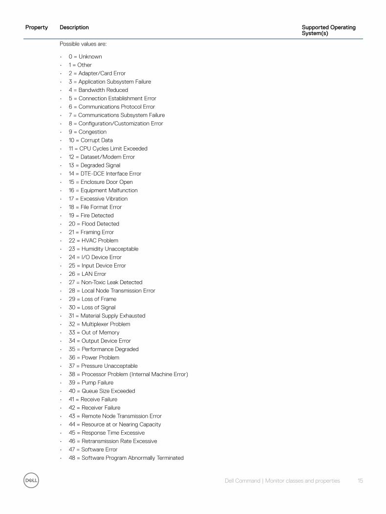
Property Description Supported Operating System(s)
Possible values are:
• 0 = Unknown
• 1 = Other
• 2 = Adapter/Card Error
• 3 = Application Subsystem Failure
• 4 = Bandwidth Reduced
• 5 = Connection Establishment Error
• 6 = Communications Protocol Error
• 7 = Communications Subsystem Failure
• 8 = Configuration/Customization Error
• 9 = Congestion
• 10 = Corrupt Data
• 11 = CPU Cycles Limit Exceeded
• 12 = Dataset/Modem Error
• 13 = Degraded Signal
• 14 = DTE-DCE Interface Error
• 15 = Enclosure Door Open
• 16 = Equipment Malfunction
• 17 = Excessive Vibration
• 18 = File Format Error
• 19 = Fire Detected
• 20 = Flood Detected
• 21 = Framing Error
• 22 = HVAC Problem
• 23 = Humidity Unacceptable
• 24 = I/O Device Error
• 25 = Input Device Error
• 26 = LAN Error
• 27 = Non-Toxic Leak Detected
• 28 = Local Node Transmission Error
• 29 = Loss of Frame
• 30 = Loss of Signal
• 31 = Material Supply Exhausted
• 32 = Multiplexer Problem
• 33 = Out of Memory
• 34 = Output Device Error
• 35 = Performance Degraded
• 36 = Power Problem
• 37 = Pressure Unacceptable
• 38 = Processor Problem (Internal Machine Error)
• 39 = Pump Failure
• 40 = Queue Size Exceeded
• 41 = Receive Failure
• 42 = Receiver Failure
• 43 = Remote Node Transmission Error
• 44 = Resource at or Nearing Capacity
• 45 = Response Time Excessive
• 46 = Retransmission Rate Excessive
• 47 = Software Error
• 48 = Software Program Abnormally Terminated
Dell Command | Monitor classes and properties 15

Property Description Supported Operating System(s)
• 49 = Software Program Error (Incorrect Results)
• 50 = Storage Capacity Problem
• 51 = Temperature Unacceptable
• 52 = Threshold Crossed
• 53 = Timing Problem
• 54 = Toxic Leak Detected
• 55 = Transmit Failure
• 56 = Transmitter Failure
• 57 = Underlying Resource Unavailable
• 58 = Version MisMatch
• 59 = Previous Alert Cleared
• 60 = Login Attempts Failed
• 61 = Software Virus Detected
• 62 = Hardware Security Breached
• 63 = Denial of Service Detected
• 64 = Security Credential MisMatch
• 65 = Unauthorized Access
• 66 = Alarm Received
• 67 = Loss of Pointer
• 68 = Payload Mismatch
• 69 = Transmission Error
• 70 = Excessive Error Rate
• 71 = Trace Problem
• 72 = Element Unavailable
• 73 = Element Missing
• 74 = Loss of Multi Frame
• 75 = Broadcast Channel Failure
• 76 = Invalid Message Received
• 77 = Routing Failure
• 78 = Backplane Failure
• 79 = Identifier Duplication
• 80 = Protection Path Failure
• 81 = Sync Loss or Mismatch
• 82 = Terminal Problem
• 83 = Real Time Clock Failure
• 84 = Antenna Failure
• 85 = Battery Charging Failure
• 86 = Disk Failure
• 87 = Frequency Hopping Failure
• 88 = Loss of Redundancy
• 89 = Power Supply Failure
• 90 = Signal Quality Problem
• 91 = Battery Discharging
• 92 = Battery Failure
• 93 = Commercial Power Problem
• 94 = Fan Failure
• 95 = Engine Failure
• 96 = Sensor Failure
• 97 = Fuse Failure
• 98 = Generator Failure
16 Dell Command | Monitor classes and properties
Property Description Supported Operating System(s)
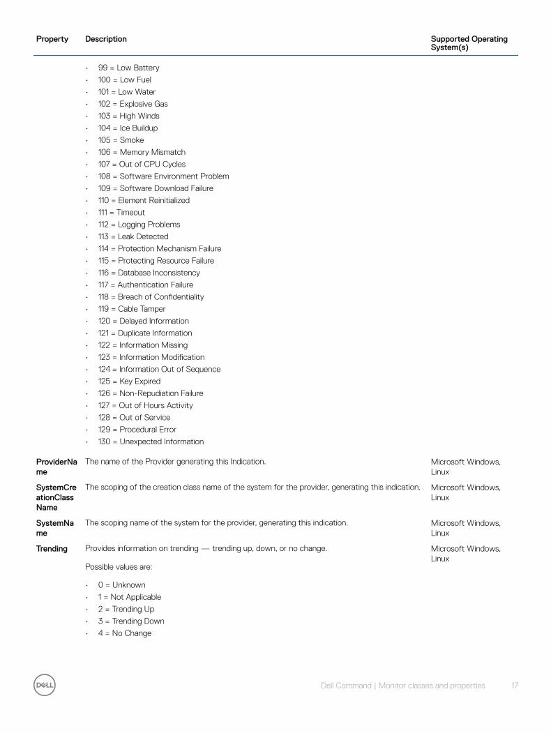
• 99 = Low Battery
• 100 = Low Fuel
• 101 = Low Water
• 102 = Explosive Gas
• 103 = High Winds
• 104 = Ice Buildup
• 105 = Smoke
• 106 = Memory Mismatch
• 107 = Out of CPU Cycles
• 108 = Software Environment Problem
• 109 = Software Download Failure
• 110 = Element Reinitialized
• 111 = Timeout
• 112 = Logging Problems
• 113 = Leak Detected
• 114 = Protection Mechanism Failure
• 115 = Protecting Resource Failure
• 116 = Database Inconsistency
• 117 = Authentication Failure
• 118 = Breach of Confidentiality
• 119 = Cable Tamper
• 120 = Delayed Information
• 121 = Duplicate Information
• 122 = Information Missing
• 123 = Information Modification
• 124 = Information Out of Sequence
• 125 = Key Expired
• 126 = Non-Repudiation Failure
• 127 = Out of Hours Activity
• 128 = Out of Service
• 129 = Procedural Error
• 130 = Unexpected Information
ProviderName
The name of the Provider generating this Indication. Microsoft Windows, Linux
SystemCreationClassName
The scoping of the creation class name of the system for the provider, generating this indication. Microsoft Windows, Linux
SystemName
The scoping name of the system for the provider, generating this indication. Microsoft Windows, Linux
Trending Provides information on trending — trending up, down, or no change.
Possible values are:
• 0 = Unknown
• 1 = Not Applicable
• 2 = Trending Up
• 3 = Trending Down
• 4 = No Change
Microsoft Windows, Linux
Dell Command | Monitor classes and properties 17
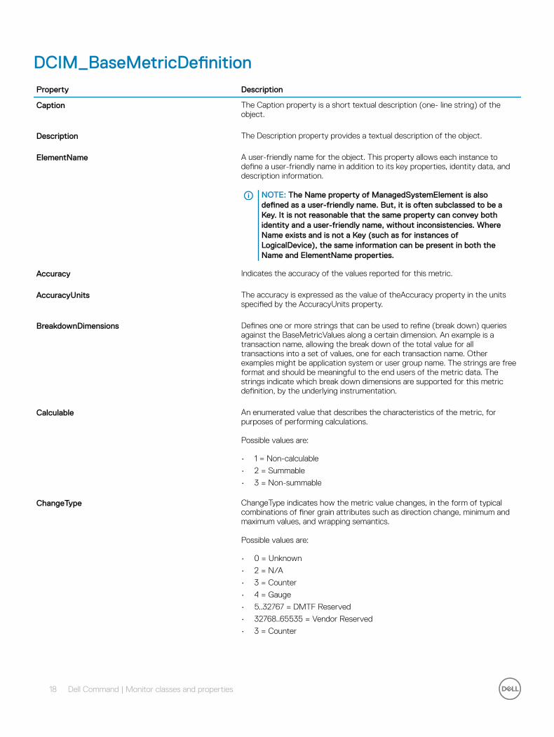
DCIM_BaseMetricDefinitionProperty Description
Caption The Caption property is a short textual description (one- line string) of the object.
Description The Description property provides a textual description of the object.
ElementName A user-friendly name for the object. This property allows each instance to define a user-friendly name in addition to its key properties, identity data, and description information.
NOTE: The Name property of ManagedSystemElement is also defined as a user-friendly name. But, it is often subclassed to be a Key. It is not reasonable that the same property can convey both identity and a user-friendly name, without inconsistencies. Where Name exists and is not a Key (such as for instances of LogicalDevice), the same information can be present in both the Name and ElementName properties.
Accuracy Indicates the accuracy of the values reported for this metric.
AccuracyUnits The accuracy is expressed as the value of theAccuracy property in the units specified by the AccuracyUnits property.
BreakdownDimensions Defines one or more strings that can be used to refine (break down) queries against the BaseMetricValues along a certain dimension. An example is a transaction name, allowing the break down of the total value for all transactions into a set of values, one for each transaction name. Other examples might be application system or user group name. The strings are free format and should be meaningful to the end users of the metric data. The strings indicate which break down dimensions are supported for this metric definition, by the underlying instrumentation.
Calculable An enumerated value that describes the characteristics of the metric, for purposes of performing calculations.
Possible values are:
• 1 = Non-calculable
• 2 = Summable
• 3 = Non-summable
ChangeType ChangeType indicates how the metric value changes, in the form of typical combinations of finer grain attributes such as direction change, minimum and maximum values, and wrapping semantics.
Possible values are:
• 0 = Unknown
• 2 = N/A
• 3 = Counter
• 4 = Gauge
• 5..32767 = DMTF Reserved
• 32768..65535 = Vendor Reserved
• 3 = Counter
18 Dell Command | Monitor classes and properties

Property Description
DataType The data type of the metric. These types represent the datatypes defined for CIM.
Possible values are:
• 1 = boolean
• 2 = char16
• 3 = datetime
• 4 = real32
• 5 = real64
• 6 = sint16
• 7 = sint32
• 8 = sint64
• 9 = sint8
• 10 = string
• 11 = uint16
• 12 = uint32
• 13 = uint64
• 14 = uint8
GatheringType GatheringType indicates how the metric values are gathered by the underlying instrumentation. This allows the client application to choose the right metric for the purpose.
Possible values are:
• 0 = Unknown
• 2 = OnChange
• 3 = Periodic
• 4 = OnRequest
• 5..32767 = DMTF Reserved
• 32768..65535 = Vendor Reserved
Id A string that uniquely identifies the metric definition. The use of OSF UUID/GUIDs is recommended.
IsContinuous True
Name The name of the metric. This name does not have to be unique, but should be descriptive and may contain blanks.
ProgrammaticUnits Identifies the specific units of a value. The value of this property shall be a legal value of the Programmatic Units qualifier as defined in Appendix C.1 of DSP0004 V2.4 or later.
SampleInterval If metric values are collected at regular intervals, the SampleInterval property indicates the length of the interval. If non-null, the value of the SampleInterval shall be expressed in interval notation. A value of NULL shall indicate the SampleInterval is unknown. A value of 99990101000000.000000+000 shall indicate the sampling interval is irregular.
TimeScope TimeScope indicates the time scope to which the metric value applies.
Possible values are:
• 0 = Unknown
• 2 = Point
• 3 = Interval
• 4 = StartupInterval
• 5..32767 = DMTF Reserved
Dell Command | Monitor classes and properties 19

Property Description
• 32768..65535 = Vendor Reserved
Units Identifies the specific units of a value. Examples are Bytes, Packets, Jobs, Files, Milliseconds, and Amps.
DCIM_CardProperty Description
CanBeFRUed Boolean that indicates whether this PhysicalElement can be FRUed (TRUE) or not (FALSE).
CreationClassName Indicates the name of the class or the subclass used in the creation of an instance. When used with the other key properties of this class, this property allows all instances of this class and its subclasses to be uniquely identified.
ElementName A user-friendly name for the object. This property allows each instance to define a user-friendly name in addition to its key properties, identity data, and description information.
NOTE: The Name property of ManagedSystemElement is also defined as a user-friendly name. But, it is often subclassed to be a Key. It is not reasonable that the same property can convey both identity and a user-friendly name, without inconsistencies. Where Name exists and is not a Key (such as for instances of LogicalDevice), the same information can be present in both the Name and ElementName properties.
HostingBoard Boolean indicating that this Card is a Motherboard or, more generically, a baseboard in a Chassis.
Manufacturer The name of the organization responsible for producing the PhysicalElement. This organization may be the entity from whom the Element is purchased, but it is not necessarily true. The latter information is contained in the Vendor property of CIM_Product.
Model The name by which the PhysicalElement is known.
PackageType Enumeration defining the type of the PhysicalPackage.
Possible values are:
• 0 = Unknown — Indicates that the package type is not known.
• 1 = Other — The package type does not correspond to an existing enumerated value. The value is specified using the OtherPackageType property.
• 2 = Rack
• 3 = Chassis/Frame
• 4 = Cross Connect/Backplane
• 5 = Container/Frame Slot
• 6 = Power Supply
• 7 = Fan
• 8 = Sensor
• 9 = Module/Card
• 10 = Port/Connector
20 Dell Command | Monitor classes and properties
Property Description
• 11 = Battery
• 12 = Processor
• 13 = Memory
• 14 = Power Source/Generator
• 15 = Storage Media Package (e.g., Disk or Tape Drive)
• 16 = Blade
• 17 = Blade Expansion
NOTE: This enumeration expands on the list in the Entity MIB (the attribute, entPhysicalClass). The numeric values are consistent with CIM's enum numbering guidelines, but are slightly different than the MIB's values.
The values Rack through Port/Connector are defined per the Entity-MIB (where the semantics of rack are equivalent to the MIB's stack value). The other values (for battery, processor, memory, power source/generator and storage media package) are self-explanatory. A value of Blade should be used when the PhysicalPackage contains the operational hardware aspects of a ComputerSystem, without the supporting mechanicals such as power and cooling. For example, a Blade Server includes processor(s) and memory, and relies on the containing chassis to supply power and cooling. In many respects, a Blade can be considered a Module/Card. However, it is tracked differently by inventory systems and differs in terms of service philosophy. For example, a Blade is intended to be hot-plugged into a hosting enclosure without requiring additional cabling, and does not require a cover to be removed from the enclosure for installation. Similarly, a Blade Expansion has characteristics of a Blade and a Module/Card. However, it is distinct from both due to inventory tracking and service philosophy, and because of its hardware dependence on a Blade. A Blade Expansion must be attached to a Blade prior to inserting the resultant assembly into an enclosure.
PartNumber The part number assigned by the organization that is responsible for producing or manufacturing the PhysicalElement.
SKU The stock-keeping unit number for this PhysicalElement.
Tag An arbitrary string that uniquely identifies the Physical Element and serves as the key of the Element. The Tag property can contain information such as asset tag or serial number data. The key for PhysicalElement is placed very high in the object hierarchy to independently identify the hardware or entity, regardless of physical placement in or on Cabinets, Adapters, and so on. For example, a hotswappable or removable component can be taken from its containing (scoping) Package and be temporarily unused. The object still continues to exist and can even be inserted into a different scoping container. Therefore, the key for Physical Element is an arbitrary string and is defined independently of any placement or location-oriented hierarchy.
Dell Command | Monitor classes and properties 21
DCIM_ChassisProperty Description
BreachDescription A free-form string providing more information if the SecurityBreach property indicates that a breach or some other security-related event occurred.
CanBeFRUed Boolean that indicates whether this PhysicalElement can be FRUed (TRUE) or not (FALSE).
ChassisPackageType Indicates the physical form factor for the type of Chassis.
Possible values are:
• 0 = Unknown
• 1 = Other
• 2 = SMBIOS Reserved
• 3 = Desktop
• 4 = Low Profile Desktop
• 5 = Pizza Box
• 6 = Mini Tower
• 7 = Tower
• 8 = Portable
• 9 = LapTop
• 10 = Notebook
• 11 = Hand Held
• 12 = Docking Station
• 13 = All in One
• 14 = Sub Notebook
• 15 = Space-Saving
• 16 = Lunch Box
• 17 = Main System Chassis
• 18 = Expansion Chassis
• 19 = SubChassis
• 20 = Bus Expansion Chassis
• 21 = Peripheral Chassis
• 22 = Storage Chassis
• 23 = SMBIOS Reseved
• 24 = Sealed-Case PC
• 25 = SMBIOS Reserved
• 26 = CompactPCI
• 27 = AdvancedTCA
• 28 = Blade Enclosure
• 29 = SMBIOS Reserved
• 30 = Tablet
• 31 = Convertible
• 32 = Detachable
• 33 = IoT Gateway
• .. = DMTF Reserved
• 0x8000..0xFFFF = Vendor Reserved
This property may have a value when the PackageType property contains the value 3 Chassis Frame. A value of 28 Blade Enclosure
22 Dell Command | Monitor classes and properties
Property Description
indicates that the Chassis is designed to contain one or more PhysicalPackage(s) of PackageType 16 Blade or PackageType 17 Blade Expansion.
ChassisTypeDescription A string providing more information on the ChassisPackageType.
CreationClassName Indicates the name of the class or the subclass used in the creation of an instance. When used with the other key properties of this class, this property allows all instances of this class and its subclasses to be uniquely identified.
ElementName A user-friendly name for the object. This property allows each instance to define a user-friendly name in addition to its key properties, identity data, and description information.
NOTE: The Name property of ManagedSystemElement is also defined as a user-friendly name. But, it is often sub-classed to be a Key. It is not reasonable that the same property can convey both identity and a user-friendly name, without inconsistencies. Where Name exists and is not a Key (such as for instances of LogicalDevice), the same information can be present in both the Name and ElementName properties.
LockPresent Boolean indicating whether the Frame is protected with a lock.
Manufacturer The name of the organization responsible for producing the PhysicalElement. This organization may be the entity from whom the Element is purchased, but this is not necessarily true. The latter information is contained in the Vendor property of CIM_Product.
Model The name by which the PhysicalElement is generally known.
Name The Name property defines the label by which the object is known. When sub-classed, the Name property can be overridden to be a Key property.
PackageType Enumeration defining the type of the PhysicalPackage.
Possible values are:
• 0 = Unknown — Indicates that the package type is not known.
• 1 = Other — The package type does not correspond to an existing enumerated value. The value is specified using the OtherPackageType property.
• 2 = Rack
• 3 = Chassis/Frame
• 4 = Cross Connect/Backplane
• 5 = Container/Frame Slot
• 6 = Power Supply
• 7 = Fan
• 8 = Sensor
• 9 = Module/Card
• 10 = Port/Connector
• 11 = Battery
• 12 = Processor
• 13 = Memory
• 14 = Power Source/Generator
• 15 = Storage Media Package (example, Disk or Tape Drive)
Dell Command | Monitor classes and properties 23
Property Description
• 16 = Blade
• 17 = Blade Expansion
NOTE: This enumeration expands on the list in the Entity MIB (the attribute, entPhysicalClass). The numeric values are consistent with CIM's enum numbering guidelines, but are slightly different than the MIB's values.
The values Rack through Port/Connector are defined per the Entity-MIB (where the semantics of rack are equivalent to the MIB's stack value).
The other values (for battery, processor, memory, power source/generator and storage media package) are self-explanatory. A value of Blade should be used when the PhysicalPackage contains the operational hardware aspects of a ComputerSystem, without the supporting mechanicals such as power and cooling. For example, a Blade Server includes processor(s) and memory, and relies on the containing chassis to supply power and cooling.
In many respects, a Blade can be considered a Module/Card. However, it is tracked differently by inventory systems and differs in terms of service philosophy. For example, a Blade is intended to be hot-plugged into a hosting enclosure without requiring additional cabling, and does not require a cover to be removed from the enclosure for installation. Similarly, a Blade Expansion has characteristics of a Blade and a Module/Card. However, it is distinct from both due to inventory tracking and service philosophy, and because of its hardware dependence on a Blade. A Blade Expansion must be attached to a Blade prior to inserting the resultant assembly into an enclosure.
PartNumber The part number assigned by the organization that is responsible for producing or manufacturing the PhysicalElement.
PropertyOwnershipTag Property Ownership Tag of a system.
SecurityBreach An enumerated, integer-valued property indicating whether a physical breach of the Frame was attempted but unsuccessful (value = 4) or attempted and successful (value = 5).
Possible values are:
• 1 = Other
• 2 = Unknown
• 3 = No Breach
• 4 = Breach Attempted
• 5 = Breach Successful
SKU The stock-keeping unit number for this PhysicalElement.
Tag An arbitrary string that uniquely identifies the Physical Element and serves as the key of the Element. The Tag property can contain information such as asset tag or serial number data. The key for PhysicalElement is placed very high in the object hierarchy in order to independently identify the hardware or entity, regardless of physical placement in or on Cabinets, Adapters, and so on. For example, a hotswappable or removable component can be taken from its containing (scoping) Package and be temporarily unused. The object still continues to exist and can even be inserted into a different scoping container. Therefore, the key for Physical Element
24 Dell Command | Monitor classes and properties

Property Description
is an arbitrary string and is defined independently of any placement or location-oriented hierarchy.
VendorCompatibilityStrings An array of strings that identify the component that is compatible with, and can be inserted in a slot that reports this string as one of the array element in the VendorCompatibilityStrings. This allows system administrators to determine whether it is appropriate to insert a package into a slot to ensure uniqueness within the NameSpace, each value defined by the vendor for use in the VendorCompatibilityStrings property SHOULD be constructed using the following preferred algorithm: : Where and are separated by a colon ':', and where MUST include a copyrighted, trademarked or otherwise unique name that is owned by the business entity creating/defining the InstanceID, or is a registered ID that is assigned to the business entity by a recognized global authority (This is similar to the _ structure of Schema class names.) In addition, to ensure uniqueness MUST NOT contain a colon (':'). When using this algorithm, the first colon to appear in InstanceID MUST appear between and . is chosen by the business entity and SHOULD not be re-used to identify different underlying (real-world) elements.
ChangePropertyOwenershipTag (Method) This method allows a user to change the Property Ownership Tag of a system.
ChangeAssetTag (Method) This method allows a user to change the Asset Tag of a system.
DCIM_ChipProperty Description
CanBeFRUed Boolean that indicates whether this PhysicalElement can be FRUed (TRUE) or not (FALSE).
CreationClassName Indicates the name of the class or the subclass used in the creation of an instance. When used with the other key properties of this class, this property allows all instances of this class and its subclasses to be uniquely identified.
ElementName A user-friendly name for the object. This property allows each instance to define a user-friendly name in addition to its key properties, identity data, and description information.
NOTE: The Name property of ManagedSystemElement is also defined as a user-friendly name. But, it is often sub classed to be a Key. It is not reasonable that the same property can convey both identity and a user-friendly name, without inconsistencies. Where Name exists and is not a Key (such as for instances of LogicalDevice), the same information can be present in both the Name and ElementName properties.
Manufacturer The name of the organization responsible for producing the PhysicalElement. This organization may be the entity from where the Element is purchased, but this is not necessarily true. The latter information is contained in the Vendor property of CIM_Product.
Model The name by which the PhysicalElement is generally known.
Dell Command | Monitor classes and properties 25

Property Description
PartNumber The part number assigned by the organization that is responsible for producing or manufacturing the PhysicalElement.
SerialNumber A manufacturer-allocated number used to identify the Physical Element.
SKU The stock-keeping unit number for this PhysicalElement.
Tag An arbitrary string that uniquely identifies the Physical Element and serves as the key of the Element. The Tag property can contain information such as asset tag or serial number data. The key for PhysicalElement is placed very high in the object hierarchy to independently identify the hardware or entity, regardless of physical placement in or on Cabinets, Adapters, and so on.
For example, a hotswappable or removable component can be taken from its containing (scoping) Package and be temporarily unused. The object still continues to exist and can even be inserted into a different scoping container. Therefore, the key for Physical Element is an arbitrary string and is defined independently of any placement or location-oriented hierarchy.
DCIM_DesktopMonitorProperty Description
Bandwidth Monitor's bandwidth in Mega Hertz. If unknown, enter 0.
Brightness This property represents the brightness/Luminance of the video output. The property value is from 0 to the MaxBrightness property value. If the Brightness property is implemented but the brightness is unknown at the time, the property has a value 0x80000000.
Caption The Caption property is a short textual description (one- line string) of the object.
ColorCodeFormatSupported Color code format supported.
ColorDepthBits Color Bit Depth.
ColorModePreset This property defines a specified color temperature of the display.
Possible values are:
• 0 = Unknown
• 2 = sRGB
• 3 = Display Native
• 4 = 4000K
• 5 = 5000K
• 6 = 6500K
• 7 = 7500K
• 8 = 8200K
• 9 = 9300K
• 1011 = 10000K
• 12 = 11500K
• 13 = User 1
• 14 = User
26 Dell Command | Monitor classes and properties

Property Description
• 2 .. = User 3
• 32768..65535 = DMTF Reserved
ColorModePresetCapabilities This property lists the allowed values for ColorModePreset.
Possible values are:
• 0 = Unknown
• 2 = sRGB
• 3 = Display Native
• 4 = 4000K
• 5 = 5000K
• 6 = 6500K
• 7 = 7500K
• 8 = 8200K
• 9 = 9300K
• 1011 = 10000K
• 12 = 11500K
• 13 = User 1
• 14 = User
• .. = User 3
• 32768..65535 = DMTF Reserved
CommunicationStatus Indicates the ability of the instrumentation to communicate with the underlying ManagedElement. A Null return indicates the implementation (provider) does not implement this property.
Possible values are:
• 0 = Unknown — Indicates that the implementation is in general capable of returning this property, but is unable to do so now.
• 1 = Not Available — Indicates that the implementation (provider) is capable of returning a value for this property, but not ever for this particular piece of hardware/software or the property is intentionally not used because it adds no meaningful information (as in the case of a property that is intended to add additional info to another property).
• 2 = Communication OK — indicates that communication is established with the element, but does not convey any quality of service.
• 3 = Lost Communication — Indicates that the Managed Element is known to exist and has been contacted successfully in the past, but is unreachable.
• 4 = No Contact — Indicates that the monitoring system has knowledge of this element, but has never been able to establish communications with it.
• .. = DMTF Reserved
• 0x8000.. = Vendor Reserved
CompositSyncSignalOnGreenVideoSupported Composite Sync Signal on Green video is supported.
CompositSyncSignalOnHorizontalSupported Composite Sync Signal on Horizontal is supported.
ContinuousFrequency For EDID 1.3, this bit indicated support for or no support for GTF(using the default GTF parameter values). For EDID 1.4 this bit has been redefined to indicate Continuous frequency(1) or Non-Continuous Frequency(0).
Dell Command | Monitor classes and properties 27
Property Description
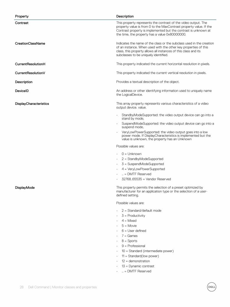
Contrast This property represents the contrast of the video output. The property value is from 0 to the MaxContrast property value. If the Contrast property is implemented but the contrast is unknown at the time, the property has a value 0x80000000.
CreationClassName Indicates the name of the class or the subclass used in the creation of an instance. When used with the other key properties of this class, this property allows all instances of this class and its subclasses to be uniquely identified.
CurrentResolutionH This property indicated the current horizontal resolution in pixels.
CurrentResolutionV This property indicated the current vertical resolution in pixels.
Description Provides a textual description of the object.
DeviceID An address or other identifying information used to uniquely name the LogicalDevice.
DisplayCharacteristics This array property represents various characteristics of a video output device. value.
• StandbyModeSupported: the video output device can go into a stand by mode,
• SuspendModeSupported: the video output device can go into a suspend mode,
• VeryLowPowerSupported: the video output goes into a low power mode. If DisplayCharacteristics is implemented but the value is unknown, the property has an Unknown
Possible values are:
• 0 = Unknown
• 2 = StandbyModeSupported
• 3 = SuspendModeSupported
• 4 = VeryLowPowerSupported
• .. = DMTF Reserved
• 32768..65535 = Vendor Reserved
DisplayMode This property permits the selection of a preset optimized by manufacturer for an application type or the selection of a user-defined setting.
Possible values are:
• 2 = Standard/default mode
• 3 = Productivity
• 4 = Mixed
• 5 = Movie
• 6 = User defined
• 7 = Games
• 8 = Sports
• 9 = Professional
• 10 = Standard (intermediate power)
• 11 = Standard(low power)
• 12 = demonstration
• 13 = Dynamic contrast
• .. = DMTF Reserved
28 Dell Command | Monitor classes and properties

Property Description
• 32768..65535 = Vendor Reserved
DisplayModeCapabilities This property lists the allowed values for DisplayMode.
Possible values are:
• 2 = Standard/default mode
• 3 = Productivity
• 4 = Mixed
• 5 = Movie
• 6 = User defined
• 7 = Games
• 8 = Sports
• 9 = Professional
• 10 = Standard (intermediate power)
• 11 = Standard(low power)
• 12 = demonstration
• 13 = Dynamic contrast
• .. = DMTF Reserved
• 32768..65535 = Vendor Reserved
EDIDGamma Display transfer characteristics(GAMMA).Range is from 1.00->3.54. GAMMA = (EDID Value + 100) / 100
EDIDVersionNumber EDID version and reversion number.
ElementName A user-friendly name for the object. This property allows each instance to define a user-friendly name in addition to its key properties, identity data, and description information.
NOTE: The Name property of ManagedSystemElement is also defined as a user-friendly name. But, it is often subclassed to be a Key. It is not reasonable that the same property can convey both identity and a user-friendly name, without inconsistencies. Where Name exists and is not a Key (such as for instances of LogicalDevice), the same information can be present in both the Name and ElementName properties.
EnabledDefault An enumerated value indicating an administrator's default or startup configuration for the Enabled State of an element.
Possible values are:
• 2 = Enabled
• 3 = Disabled
• 5 = Not Applicable
• 6 = Enabled but Offline
• 7 = No Default
• 9 = Quiesce
• .. = DMTF Reserved
• 32768..65535 = Vendor Reserved
By default, the element is Enabled (value = 2).
EnabledState An integer enumeration that indicates the enabled and disabled states of an element. It can also indicate the transitions between
Dell Command | Monitor classes and properties 29

Property Description
these requested states. For example, shutting down (value = 4) and starting (value = 10) are transient states between enabled and disabled.
Possible values are:
• 0 = Unknown
• 1 = Other
• 2 = Enabled — Indicates that the element is or could be executing commands, will process any queued commands, and queues new requests.
• 3 = Disabled — Indicates that the element will not run commands and drops any new requests.
• 4 = Shutting Down — Indicates that the element is in the process of going to a Disabled state.
• 5 = Not Applicable — Indicates that the element does not support being enabled or disabled.
• 6 = Enabled but Offline — Indicates that the element may be completing commands, and drops any new requests.
• 7 = In Test — Indicates that the element is in a test state.
• 8 = Deferred — Indicates that the element may be completing commands, but queues any new requests.
• 9 = Quiesce — Indicates that the element is enabled but in a restricted mode.
• 10 = Starting — Indicates that the element is in the process of going to an Enabled state. New requests are queued.
• 11..32767 = DMTF Reserved
• 32768..65535 = Vendor Reserved
FrequencyH This property is a horizontal synchronization signal frequency in Hz as determined by the display.
FrequencyV This property is a vertical synchronization signal frequency in Hz as determined by the display.
HealthState Indicates the current health of the element. This attribute expresses the health of this element but not necessarily that of its subcomponents.
Possible values are:
• 0 = Unknown — The implementation cannot report on HealthState now. DMTF has reserved the unused portion of the continuum for additional HealthStates in the future.
• 5 = OK — The element is fully functional and is operating within normal operational parameters and without error.
• 10 = Degraded/Warning — The element is in working order and all functionality is provided. However, the element is not working to the best of its abilities. For example, the element may not be operating at optimal performance or it may be reporting recoverable errors.
• 15 = Minor failure — All functionality is available but some may be degraded.
• 20 = Major failure — The element is failing. It is possible that some or all of the functionality of this component is degraded or not working.
• 25 = Critical failure — The element is nonfunctional and recovery may not be possible.
• 30 = Non-recoverable error — The element has failed, and recovery is not possible. All functionality provided by this element has been lost.
30 Dell Command | Monitor classes and properties

Property Description
• .. = DMTF Reserved
IdentifyingDescriptions An array of free-form strings providing explanations and details behind the entries in the OtherIdentifyingInfo array. Each entry of this array is related to the entry in OtherIdentifyingInfo that is located at the same index.
InputAnalog Input is an analog video signal interface.
InputDigital Input is a digital video signal interface.
InputDisplayPort DisplayPort is supported.
InputDVI DVI is supported.
InputHDMI HDMI is supported.
InputSource An enumerated value identifying the current input source. Writing a new value into this property changes the device's input source to the specified value, if the value is supported as specified in InputSourceCapabilities. If the requested value is not in InputSourceCapabilities, then the current value of InputSource is unchanged.
Possible values are:
• 0 = Unknown
• 2 = Analog Video (R/G/B) #1
• 3 = Analog Video (R/G/B) #2
• 4 = Digital Video (TMDS) #1
• 5 = Digital Video (TMDS) #2
• 6 = Composite Video #1
• 7 = Composite Video #2
• 8 = S-video #1
• 9 = S-video #2
• 1011 = Tuner - Analog #1
• 12 = Tuner - Analog #2
• 13 = Tuner - Digital #1
• 14 = Tuner - Digital #2
• 15 = Component Video #1
• 16 = Component Video #2
• 17 = Component Video #3
• 18 = Digital Video (DisplayPort)
• #1 .. = Digital Video (DisplayPort)
• #2 32768..65535 = DMTF Reserved
InputSourceCapabilities This property lists the allowed values for InputSource.
Possible values are:
• 2 = Analog Video (R/G/B) #1
• 3 = Analog Video (R/G/B) #2
• 4 = Digital Video (TMDS) #1
• 5 = Digital Video (TMDS) #2
• 6 = Composite Video #1
• 7 = Composite Video #2
Dell Command | Monitor classes and properties 31

Property Description
• 8 = S-video #1
• 9 = S-video #2
• 1011 = Tuner - Analog #1
• 12 = Tuner - Analog #2
• 13 = Tuner - Digital #1
• 14 = Tuner - Digital #2
• 15 = Component Video #1
• 16 = Component Video #2
• 17 = Component Video #3
• 18 = Digital Video (DisplayPort)
• #1 .. = Digital Video (DisplayPort)
• #2 32768..65535 = DMTF Reserved
MaxBrightness This property defines the maximum value of brightness of the video output device. Different manufacturers may have different values.
MaxContrast This property represents the maximum value of contrast of the video output device. Different manufacturers may have different values.
MaxQuiesceTime The use of this property has been deprecated. When evaluating the use of Quiesce, it was determined that this single property is not adequate for describing when a device will automatically exit a quiescent state. In fact, the most likely scenario for a device to exit a quiescent state was determined to be based on the number of outstanding requests queued rather than on a maximum time. This decision is reevaluated and later. Deprecated description: Maximum time, in milliseconds, that a Device can run in a Quiesced state. The state is defined in its Availability and AdditionalAvailability properties, where Quiesced is conveyed by the value 21. What occurs at the end of the time limit is device-specific. The Device can unquiesce, can be offline, or can take other actions. A value of 0 indicates that a Device can remain quiesced indefinitely.
MCCSVersionNumber This property represents the version number of the Monitor Command and Control Set (MCCS) standard recognized by the display.
OperationalStatus Indicates the current statuses of the element. Various operational statuses are defined. Many of the enumeration's values are self-explanatory.
Possible values are:
• 0 = Unknown
• 1 = Other
• 2 = OK
• 3 = Degraded
• 4 = Stressed — Indicates that the element is functioning, but needs attention. Examples of Stressed states are overload, overheated, and so on.
• 5 = Predictive Failure — Indicates that an element is functioning nominally but predicting a failure soon.
• 6 = Error
• 7 = Non-Recoverable Error
• 8 = Starting
• 9 = Stopping
• 10 = Stopped — Implies a clean and orderly stop
32 Dell Command | Monitor classes and properties
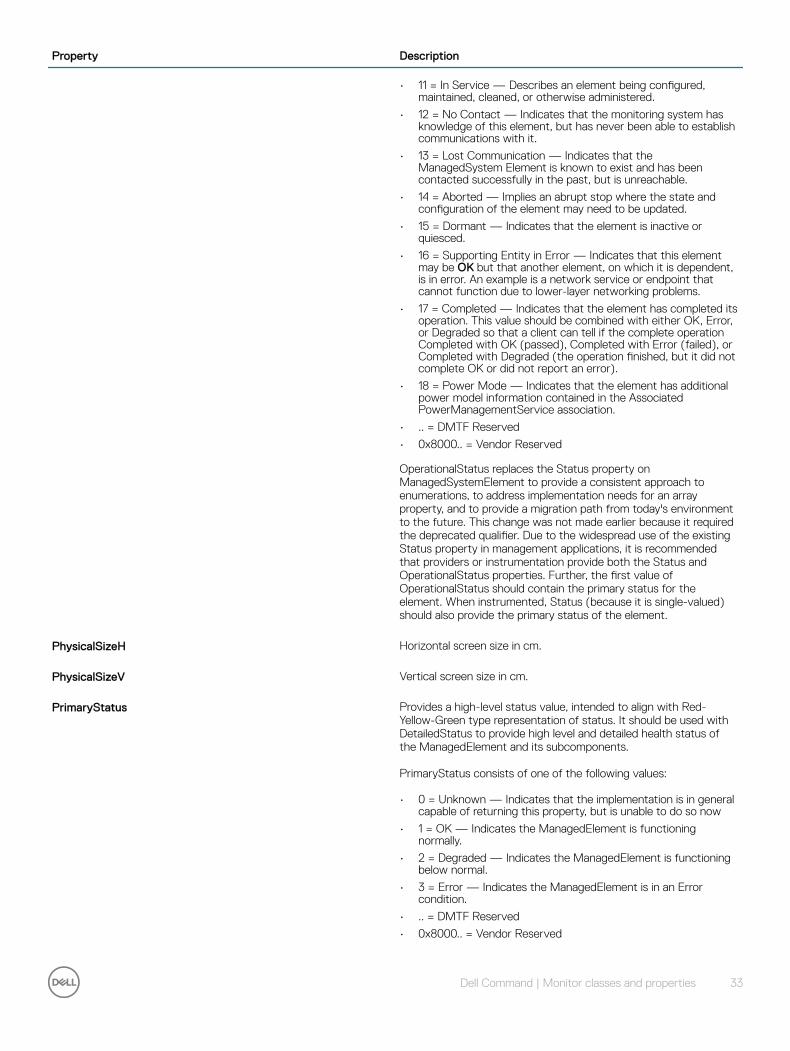
Property Description
• 11 = In Service — Describes an element being configured, maintained, cleaned, or otherwise administered.
• 12 = No Contact — Indicates that the monitoring system has knowledge of this element, but has never been able to establish communications with it.
• 13 = Lost Communication — Indicates that the ManagedSystem Element is known to exist and has been contacted successfully in the past, but is unreachable.
• 14 = Aborted — Implies an abrupt stop where the state and configuration of the element may need to be updated.
• 15 = Dormant — Indicates that the element is inactive or quiesced.
• 16 = Supporting Entity in Error — Indicates that this element may be OK but that another element, on which it is dependent, is in error. An example is a network service or endpoint that cannot function due to lower-layer networking problems.
• 17 = Completed — Indicates that the element has completed its operation. This value should be combined with either OK, Error, or Degraded so that a client can tell if the complete operation Completed with OK (passed), Completed with Error (failed), or Completed with Degraded (the operation finished, but it did not complete OK or did not report an error).
• 18 = Power Mode — Indicates that the element has additional power model information contained in the Associated PowerManagementService association.
• .. = DMTF Reserved
• 0x8000.. = Vendor Reserved
OperationalStatus replaces the Status property on ManagedSystemElement to provide a consistent approach to enumerations, to address implementation needs for an array property, and to provide a migration path from today's environment to the future. This change was not made earlier because it required the deprecated qualifier. Due to the widespread use of the existing Status property in management applications, it is recommended that providers or instrumentation provide both the Status and OperationalStatus properties. Further, the first value of OperationalStatus should contain the primary status for the element. When instrumented, Status (because it is single-valued) should also provide the primary status of the element.
PhysicalSizeH Horizontal screen size in cm.
PhysicalSizeV Vertical screen size in cm.
PrimaryStatus Provides a high-level status value, intended to align with Red-Yellow-Green type representation of status. It should be used with DetailedStatus to provide high level and detailed health status of the ManagedElement and its subcomponents.
PrimaryStatus consists of one of the following values:
• 0 = Unknown — Indicates that the implementation is in general capable of returning this property, but is unable to do so now
• 1 = OK — Indicates the ManagedElement is functioning normally.
• 2 = Degraded — Indicates the ManagedElement is functioning below normal.
• 3 = Error — Indicates the ManagedElement is in an Error condition.
• .. = DMTF Reserved
• 0x8000.. = Vendor Reserved
Dell Command | Monitor classes and properties 33

Property Description
ProductCode Product code of this monitor.
RequestedState An integer enumeration that indicates the last requested or desired state for the element, irrespective of the mechanism through which it was requested. The actual state of the element is represented by EnabledState. This property is provided to compare the last requested and current enabled or disabled states. When EnabledState is set to 5 (Not Applicable), then this property has no meaning. Refer to the EnabledState property description for explanations of the values in the RequestedState enumeration. Unknown (0) indicates that the last requested state for the element is unknown.
NOTE: The value No Change (5) has been deprecated instead of indicating the last requested state is Unknown (0). If the last requested or desired state is unknown, RequestedState should have the value Unknown (0), but may have the value No Change (5).Offline (6) indicates that the element has been requested to transition to the Enabled but Offline EnabledState. There are two new values in RequestedState that build on the statuses of EnabledState. These are Reboot (10) and Reset (11). Shut Down requests an orderly transition to the Disabled state, and may involve removing power, to completely erase any existing state. The Disabled state requests an immediate disabling of the element, such that it will not execute or accept any commands or processing requests. This property is set as the result of a method invocation (such as Start or StopService on CIM_Service), or can be overridden and defined as WRITEable in a subclass. The method approach is considered superior to a WRITEable property, because it allows an explicit invocation of the operation and the return of a result code. If knowledge of the last RequestedState is not supported for the EnabledLogicalElement, the property is NULL or has the value 12 Not Applicable.
Possible values are:
• 0 = Unknown
• 2 = Enabled
• 3 = Disabled
• 4 = Shut Down
• 5 = No Change
• 6 = Offline
• 7 = Test
• 8 = Deferred
• 9 = Quiesce
• 10 = Reboot — Refers to doing a Shut Down and then moving to an Enabled state.
• 11 = Reset — Indicates that the element is first Disabled and then Enabled.
• 12 = Not Applicable
• .. = DMTF Reserved
• 32768..65535 = Vendor Reserved
ScalerManufacturer The name of the manufacturer of the controller chip used in a particular display.
34 Dell Command | Monitor classes and properties
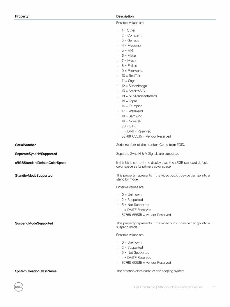
Property Description
Possible values are:
• 1 = Other
• 2 = Conexant
• 3 = Genesis
• 4 = Macronix
• 5 = MRT
• 6 = Mstar
• 7 = Myson
• 8 = Philips
• 9 = Pixelworks
• 10 = RealTek
• 11 = Sage
• 12 = SiliconImage
• 13 = SmartASIC
• 14 = STMicroelectronics
• 15 = Topro
• 16 = Trumpion
• 17 = WellTrend
• 18 = Samsung
• 19 = Novatek
• 20 = STK
• .. = DMTF Reserved
• 32768..65535 = Vendor Reserved
SerialNumber Serial number of the monitor. Come from EDID.
SeparateSyncHVSupported Separate Sync H & V Signals are supported.
sRGBStandardDefaultColorSpace If this bit is set to 1, the display uses the sRGB standard default color space as its primary color space.
StandbyModeSupported This property represents if the video output device can go into a stand by mode.
Possible values are:
• 0 = Unknown
• 2 = Supported
• 3 = Not Supported
• .. = DMTF Reserved
• 32768..65535 = Vendor Reserved
SuspendModeSupported This property represents if the video output device can go into a suspend mode.
Possible values are:
• 0 = Unknown
• 2 = Supported
• 3 = Not Supported
• .. = DMTF Reserved
• 32768..65535 = Vendor Reserved
SystemCreationClassName The creation class name of the scoping system.
Dell Command | Monitor classes and properties 35
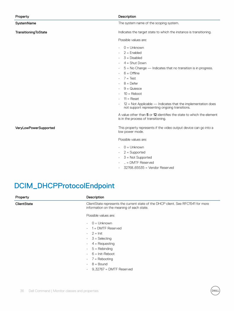
Property Description
SystemName The system name of the scoping system.
TransitioningToState Indicates the target state to which the instance is transitioning.
Possible values are:
• 0 = Unknown
• 2 = Enabled
• 3 = Disabled
• 4 = Shut Down
• 5 = No Change — Indicates that no transition is in progress.
• 6 = Offline
• 7 = Test
• 8 = Defer
• 9 = Quiesce
• 10 = Reboot
• 11 = Reset
• 12 = Not Applicable — Indicates that the implementation does not support representing ongoing transitions.
A value other than 5 or 12 identifies the state to which the element is in the process of transitioning.
VeryLowPowerSupported This property represents if the video output device can go into a low power mode.
Possible values are:
• 0 = Unknown
• 2 = Supported
• 3 = Not Supported
• .. = DMTF Reserved
• 32768..65535 = Vendor Reserved
DCIM_DHCPProtocolEndpointProperty Description
ClientState ClientState represents the current state of the DHCP client. See RFC1541 for more information on the meaning of each state.
Possible values are:
• 0 = Unknown
• 1 = DMTF Reserved
• 2 = Init
• 3 = Selecting
• 4 = Requesting
• 5 = Rebinding
• 6 = Init-Reboot
• 7 = Rebooting
• 8 = Bound
• 9..32767 = DMTF Reserved
36 Dell Command | Monitor classes and properties
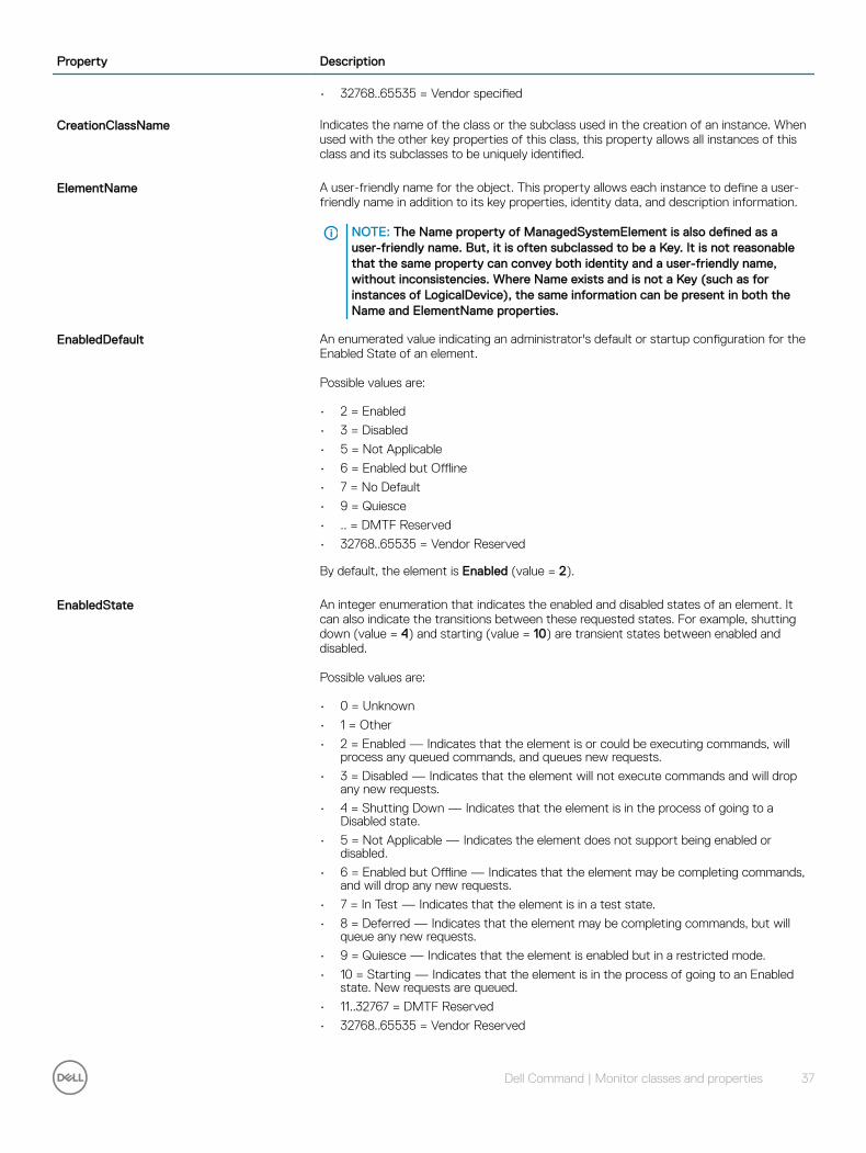
Property Description
• 32768..65535 = Vendor specified
CreationClassName Indicates the name of the class or the subclass used in the creation of an instance. When used with the other key properties of this class, this property allows all instances of this class and its subclasses to be uniquely identified.
ElementName A user-friendly name for the object. This property allows each instance to define a user-friendly name in addition to its key properties, identity data, and description information.
NOTE: The Name property of ManagedSystemElement is also defined as a user-friendly name. But, it is often subclassed to be a Key. It is not reasonable that the same property can convey both identity and a user-friendly name, without inconsistencies. Where Name exists and is not a Key (such as for instances of LogicalDevice), the same information can be present in both the Name and ElementName properties.
EnabledDefault An enumerated value indicating an administrator's default or startup configuration for the Enabled State of an element.
Possible values are:
• 2 = Enabled
• 3 = Disabled
• 5 = Not Applicable
• 6 = Enabled but Offline
• 7 = No Default
• 9 = Quiesce
• .. = DMTF Reserved
• 32768..65535 = Vendor Reserved
By default, the element is Enabled (value = 2).
EnabledState An integer enumeration that indicates the enabled and disabled states of an element. It can also indicate the transitions between these requested states. For example, shutting down (value = 4) and starting (value = 10) are transient states between enabled and disabled.
Possible values are:
• 0 = Unknown
• 1 = Other
• 2 = Enabled — Indicates that the element is or could be executing commands, will process any queued commands, and queues new requests.
• 3 = Disabled — Indicates that the element will not execute commands and will drop any new requests.
• 4 = Shutting Down — Indicates that the element is in the process of going to a Disabled state.
• 5 = Not Applicable — Indicates the element does not support being enabled or disabled.
• 6 = Enabled but Offline — Indicates that the element may be completing commands, and will drop any new requests.
• 7 = In Test — Indicates that the element is in a test state.
• 8 = Deferred — Indicates that the element may be completing commands, but will queue any new requests.
• 9 = Quiesce — Indicates that the element is enabled but in a restricted mode.
• 10 = Starting — Indicates that the element is in the process of going to an Enabled state. New requests are queued.
• 11..32767 = DMTF Reserved
• 32768..65535 = Vendor Reserved
Dell Command | Monitor classes and properties 37
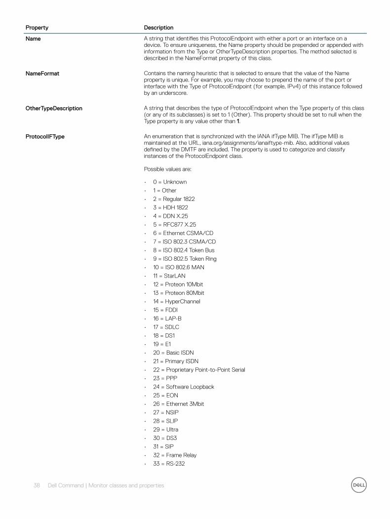
Property Description
Name A string that identifies this ProtocolEndpoint with either a port or an interface on a device. To ensure uniqueness, the Name property should be prepended or appended with information from the Type or OtherTypeDescription properties. The method selected is described in the NameFormat property of this class.
NameFormat Contains the naming heuristic that is selected to ensure that the value of the Name property is unique. For example, you may choose to prepend the name of the port or interface with the Type of ProtocolEndpoint (for example, IPv4) of this instance followed by an underscore.
OtherTypeDescription A string that describes the type of ProtocolEndpoint when the Type property of this class (or any of its subclasses) is set to 1 (Other). This property should be set to null when the Type property is any value other than 1.
ProtocolIFType An enumeration that is synchronized with the IANA ifType MIB. The ifType MIB is maintained at the URL, iana.org/assignments/ianaiftype-mib. Also, additional values defined by the DMTF are included. The property is used to categorize and classify instances of the ProtocolEndpoint class.
Possible values are:
• 0 = Unknown
• 1 = Other
• 2 = Regular 1822
• 3 = HDH 1822
• 4 = DDN X.25
• 5 = RFC877 X.25
• 6 = Ethernet CSMA/CD
• 7 = ISO 802.3 CSMA/CD
• 8 = ISO 802.4 Token Bus
• 9 = ISO 802.5 Token Ring
• 10 = ISO 802.6 MAN
• 11 = StarLAN
• 12 = Proteon 10Mbit
• 13 = Proteon 80Mbit
• 14 = HyperChannel
• 15 = FDDI
• 16 = LAP-B
• 17 = SDLC
• 18 = DS1
• 19 = E1
• 20 = Basic ISDN
• 21 = Primary ISDN
• 22 = Proprietary Point-to-Point Serial
• 23 = PPP
• 24 = Software Loopback
• 25 = EON
• 26 = Ethernet 3Mbit
• 27 = NSIP
• 28 = SLIP
• 29 = Ultra
• 30 = DS3
• 31 = SIP
• 32 = Frame Relay
• 33 = RS-232
38 Dell Command | Monitor classes and properties
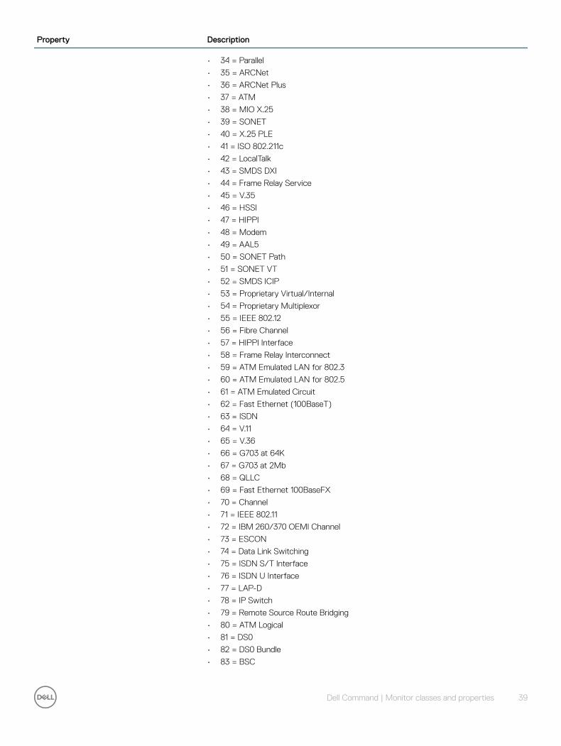
Property Description
• 34 = Parallel
• 35 = ARCNet
• 36 = ARCNet Plus
• 37 = ATM
• 38 = MIO X.25
• 39 = SONET
• 40 = X.25 PLE
• 41 = ISO 802.211c
• 42 = LocalTalk
• 43 = SMDS DXI
• 44 = Frame Relay Service
• 45 = V.35
• 46 = HSSI
• 47 = HIPPI
• 48 = Modem
• 49 = AAL5
• 50 = SONET Path
• 51 = SONET VT
• 52 = SMDS ICIP
• 53 = Proprietary Virtual/Internal
• 54 = Proprietary Multiplexor
• 55 = IEEE 802.12
• 56 = Fibre Channel
• 57 = HIPPI Interface
• 58 = Frame Relay Interconnect
• 59 = ATM Emulated LAN for 802.3
• 60 = ATM Emulated LAN for 802.5
• 61 = ATM Emulated Circuit
• 62 = Fast Ethernet (100BaseT)
• 63 = ISDN
• 64 = V.11
• 65 = V.36
• 66 = G703 at 64K
• 67 = G703 at 2Mb
• 68 = QLLC
• 69 = Fast Ethernet 100BaseFX
• 70 = Channel
• 71 = IEEE 802.11
• 72 = IBM 260/370 OEMI Channel
• 73 = ESCON
• 74 = Data Link Switching
• 75 = ISDN S/T Interface
• 76 = ISDN U Interface
• 77 = LAP-D
• 78 = IP Switch
• 79 = Remote Source Route Bridging
• 80 = ATM Logical
• 81 = DS0
• 82 = DS0 Bundle
• 83 = BSC
Dell Command | Monitor classes and properties 39

Property Description
• 84 = Async
• 85 = Combat Net Radio
• 86 = ISO 802.5r DTR
• 87 = Ext Pos Loc Report System
• 88 = AppleTalk Remote Access Protocol
• 89 = Proprietary Connectionless
• 90 = ITU X.29 Host PAD
• 91 = ITU X.3 Terminal PAD
• 92 = Frame Relay MPI
• 93 = ITU X.213
• 94 = ADSL
• 95 = RADSL
• 96 = SDSL
• 97 = VDSL
• 98 = ISO 802.5 CRFP
• 99 = Myrinet
• 100 = Voice Receive and Transmit
• 101 = Voice Foreign Exchange Office
• 102 = Voice Foreign Exchange Service
• 103 = Voice Encapsulation
• 104 = Voice over IP
• 105 = ATM DXI
• 106 = ATM FUNI
• 107 = ATM IMA
• 108 = PPP Multilink Bundle
• 109 = IP over CDLC
• 110 = IP over CLAW
• 111 = Stack to Stack
• 112 = Virtual IP Address
• 113 = MPC
• 114 = IP over ATM
• 115 = ISO 802.5j Fibre Token Ring
• 116 = TDLC
• 117 = Gigabit Ethernet
• 118 = HDLC
• 119 = LAP-F
• 120 = V.37
• 121 = X.25 MLP
• 122 = X.25 Hunt Group
• 123 = Transp HDLC
• 124 = Interleave Channel
• 125 = FAST Channel
• 126 = IP (for APPN HPR in IP Networks)
• 127 = CATV MAC Layer
• 128 = CATV Downstream
• 129 = CATV Upstream
• 130 = Avalon 12MPP Switch
• 131 = Tunnel
• 132 = Coffee
• 133 = Circuit Emulation Service
40 Dell Command | Monitor classes and properties
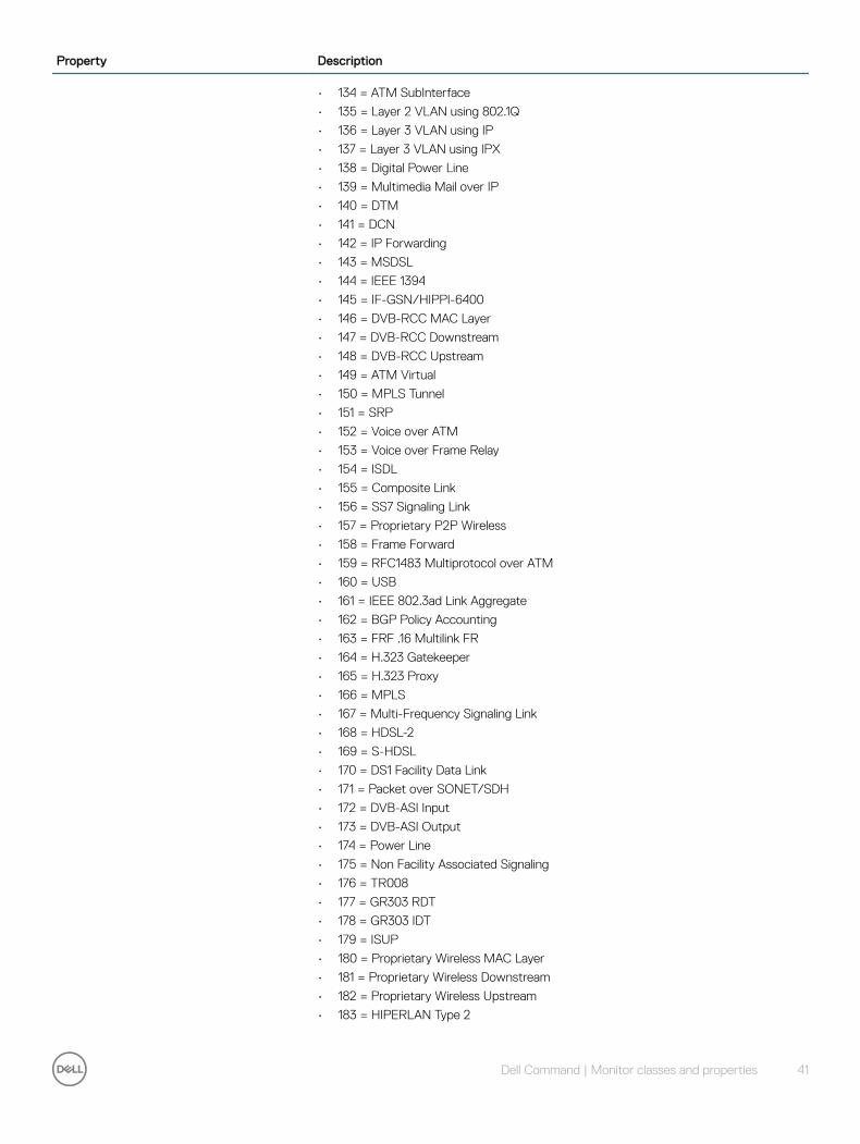
Property Description
• 134 = ATM SubInterface
• 135 = Layer 2 VLAN using 802.1Q
• 136 = Layer 3 VLAN using IP
• 137 = Layer 3 VLAN using IPX
• 138 = Digital Power Line
• 139 = Multimedia Mail over IP
• 140 = DTM
• 141 = DCN
• 142 = IP Forwarding
• 143 = MSDSL
• 144 = IEEE 1394
• 145 = IF-GSN/HIPPI-6400
• 146 = DVB-RCC MAC Layer
• 147 = DVB-RCC Downstream
• 148 = DVB-RCC Upstream
• 149 = ATM Virtual
• 150 = MPLS Tunnel
• 151 = SRP
• 152 = Voice over ATM
• 153 = Voice over Frame Relay
• 154 = ISDL
• 155 = Composite Link
• 156 = SS7 Signaling Link
• 157 = Proprietary P2P Wireless
• 158 = Frame Forward
• 159 = RFC1483 Multiprotocol over ATM
• 160 = USB
• 161 = IEEE 802.3ad Link Aggregate
• 162 = BGP Policy Accounting
• 163 = FRF .16 Multilink FR
• 164 = H.323 Gatekeeper
• 165 = H.323 Proxy
• 166 = MPLS
• 167 = Multi-Frequency Signaling Link
• 168 = HDSL-2
• 169 = S-HDSL
• 170 = DS1 Facility Data Link
• 171 = Packet over SONET/SDH
• 172 = DVB-ASI Input
• 173 = DVB-ASI Output
• 174 = Power Line
• 175 = Non Facility Associated Signaling
• 176 = TR008
• 177 = GR303 RDT
• 178 = GR303 IDT
• 179 = ISUP
• 180 = Proprietary Wireless MAC Layer
• 181 = Proprietary Wireless Downstream
• 182 = Proprietary Wireless Upstream
• 183 = HIPERLAN Type 2
Dell Command | Monitor classes and properties 41

Property Description
• 184 = Proprietary Broadband Wireless Access Point to Mulipoint
• 185 = SONET Overhead Channel
• 186 = Digital Wrapper Overhead Channel
• 187 = ATM Adaptation Layer 2
• 188 = Radio MAC
• 189 = ATM Radio
• 190 = Inter Machine Trunk
• 191 = MVL DSL
• 192 = Long Read DSL
• 193 = Frame Relay DLCI Endpoint
• 194 = ATM VCI Endpoint
• 195 = Optical Channel
• 196 = Optical Transport
• 197 = Proprietary ATM
• 198 = Voice over Cable
• 199 = Infiniband
• 200 = TE Link
• 201 = Q.2931
• 202 = Virtual Trunk Group
• 203 = SIP Trunk Group
• 204 = SIP Signaling
• 205 = CATV Upstream Channel
• 206 = Econet
• 207 = FSAN 155Mb PON
• 208 = FSAN 622Mb PON
• 209 = Transparent Bridge
• 210 = Line Group
• 211 = Voice E&M Feature Group
• 212 = Voice FGD EANA
• 213 = Voice DID
• 214 = MPEG Transport
• 215 = 6To4
• 216 = GTP
• 217 = Paradyne EtherLoop 1
• 218 = Paradyne EtherLoop 2
• 219 = Optical Channel Group
• 220 = HomePNA
• 221 = GFP
• 222 = ciscoISLvlan
• 223 = actelisMetaLOOP
• 224 = Fcip
• 225..4095 = IANA Reserved
• 4096 = IPv4
• 4097 = IPv6
• 4098 = IPv4/v6
• 4099 = IPX
• 4100 = DECnet
• 4101 = SNA
• 4102 = CONP
• 4103 = CLNP
42 Dell Command | Monitor classes and properties

Property Description
• 4104 = VINES
• 4105 = XNS
• 4106 = ISDN B Channel Endpoint
• 4107 = ISDN D Channel Endpoint
• 4108 = BGP
• 4109 = OSPF
• 4110 = UDP
• 4111 = TCP
• 4112 = 802.11a
• 4113 = 802.11b
• 4114 = 802.11g
• 4115 = 802.11h
• 4200 = NFS
• 4201 = CIFS
• 4202 = DAFS
• 4203 = WebDAV
• 4204 = HTTP
• 4205 = FTP
• 4300 = NDMP
• 4400 = Telnet
• 4401 = SSH
• 4402 = SM CLP
• 4403 = SMTP
• 4404 = LDAP
• 4405 = RDP
• 4406 = HTTPS
• .. = DMTF Reserved
• 32768.. = Vendor Reserved
NOTE: If the ProtocolIFType is set to 1 (Other), then the type information should be provided in the OtherTypeDescription string property.
RequestedState An integer enumeration that indicates the last requested or desired state for the element, irrespective of the mechanism through which it was requested. The actual state of the element is represented by EnabledState. This property is provided to compare the last requested and current enabled or disabled states.
NOTE: When EnabledState is set to 5 (Not Applicable), then this property has no meaning. See the EnabledState property description for explanations of the values in the RequestedState enumeration.
NOTE: The value No Change (5) has been deprecated instead of indicating the last requested state is Unknown (0). If the last requested or desired state is unknown, RequestedState should have the value Unknown (0), but may have the value No Change (5).
There are two new values in RequestedState that build on the statuses of EnabledState. These are Reboot (10) and Reset (11).
Shut Down requests an orderly transition to the Disabled state, and may involve removing power, to completely erase any existing state. The Disabled state requests an immediate disabling of the element, such that it will not execute or accept any commands or processing requests. This property is set as the result of a method invocation (such as Start or StopService on CIM_Service), or can be overridden and defined as WRITEable in a subclass. The method approach is considered superior to a WRITEable property, because it allows an explicit invocation of the operation and the return of a result code. If
Dell Command | Monitor classes and properties 43
Property Description
knowledge of the last RequestedState is not supported for the EnabledLogicalElement, the property is NULL or has the value 12 Not Applicable.
Possible values are:
• 0 = Unknown — Indicates the last requested state for the element is unknown.
• 2 = Enabled
• 3 = Disabled
• 4 = Shut Down
• 5 = No Change
• 6 = Offline — Indicates that the element has been requested to transition to the Enabled but Offline EnabledState.
• 7 = Test
• 8 = Deferred
• 9 = Quiesce
• 10 = Reboot — Refers to performing a Shut Down and then moving to an Enabled state.
• 11 = Reset — Indicates that the element is first Disabled and then Enabled.
• 12 = Not Applicable
• .. = DMTF Reserved
• 32768..65535 = Vendor Reserved
SystemCreationClassName The CreationClassName of the scoping System.
SystemName The Name of the scoping System.
TransitioningToState Indicates the target state to which the instance is transitioning.
Possible values are:
• 0 = Unknown
• 2 = Enabled
• 3 = Disabled
• 4 = Shut Down
• 5 = No Change — Indicates that no transition is in progress.
• 6 = Offline
• 7 = Test
• 8 = Defer
• 9 = Quiesce
• 10 = Reboot
• 11 = Reset
• 12 = Not Applicable — Indicates the implementation does not support representing ongoing transitions.
A value other than 5 or 12 identifies the state to which the element is in the process of transitioning.
44 Dell Command | Monitor classes and properties

DCIM_EthernetPortProperty Description
CreationClassName Indicates the name of the class or the subclass used in the creation of an instance. When used with the other key properties of this class, this property allows all instances of this class and its subclasses to be uniquely identified.
DeviceID An address or other identifying information used to uniquely name the LogicalDevice.
ElementName A user-friendly name for the object. This property allows each instance to define a user-friendly name in addition to its key properties, identity data, and description information.
NOTE: The Name property of ManagedSystemElement is also defined as a user-friendly name. But, it is often subclassed to be a Key. It is not reasonable that the same property can convey both identity and a user-friendly name, without inconsistencies. Where Name exists and is not a Key (such as for instances of LogicalDevice), the same information can be present in both the Name and ElementName properties.
EnabledDefault An enumerated value indicating an administrator's default or startup configuration for the Enabled State of an element.
Possible values are:
• 2 = Enabled
• 3 = Disabled
• 5 = Not Applicable
• 6 = Enabled but Offline
• 7 = No Default
• 9 = Quiesce
• .. = DMTF Reserved
• 32768..65535 = Vendor Reserved
By default, the element is Enabled (value = 2).
EnabledState An integer enumeration that indicates the enabled and disabled states of an element. It can also indicate the transitions between these requested states. For example, shutting down (value = 4) and starting (value = 10) are transient states between enabled and disabled.
Possible values are:
• 0 = Unknown
• 1 = Other
• 2 = Enabled — Indicates that the element is or could be executing commands, will process any queued commands, and queues new requests.
• 3 = Disabled — Indicates that the element does not run commands and will drop any new requests.
• 4 = Shutting Down — Indicates that the element is in the process of moving to a Disabled state.
• 5 = Not Applicable — Indicates the element does not support being enabled or disabled.
• 6 = Enabled but Offline — Indicates that the element may be completing commands, and will drop any new requests.
• 7 = In Test — Indicates that the element is in a test state.
• 8 = Deferred — Indicates that the element may be completing commands, but will queue any new requests.
• 9 = Quiesce — Indicates that the element is enabled but in a restricted mode. Starting (10) indicates that the element is in the process of going to an Enabled state. New requests are queued.
• 10 = Starting
• 11..32767 = DMTF Reserved
Dell Command | Monitor classes and properties 45

Property Description
• 32768..65535 = Vendor Reserved
Linktechnology An enumeration of the types of links. When set to 1 (Other), the related property OtherLinkTechnology contains a string description of the type of link.
Possible values are:
• 0 = Unknown
• 1 = Other
• 2 = Ethernet
• 3 = IB
• 4 = FC
• 5 = FDDI
• 6 = ATM
• 7 = Token Ring
• 8 = Frame Relay
• 9 = Infrared
• 10 = Bluetooth
• 11 = Wireless LAN
Name The Name property defines the label by which the object is known. When subclassed, the Name property can be overridden to be a Key property.
RequestedState An integer enumeration that indicates the last requested or desired state for the element, irrespective of the mechanism through which it was requested. The actual state of the element is represented by EnabledState. This property is provided to compare the last requested and current enabled or disabled states. Note that when EnabledState is set to 5 (Not Applicable), then this property has no meaning. See the EnabledState property description for explanations of the values in the RequestedState enumeration. Unknown (0) indicates the last requested state for the element is unknown.
NOTE: The value No Change (5) has been deprecated instead of indicating the last requested state is Unknown (0). If the last requested or desired state is unknown, RequestedState should have the value Unknown (0), but may have the value No Change (5). There are two new values in RequestedState that build on the statuses of EnabledState. These are Reboot (10) and Reset (11).
Shut Down requests an orderly transition to the Disabled state, and may involve removing power, to completely erase any existing state. The Disabled state requests an immediate disabling of the element, such that it will not execute or accept any commands or processing requests. This property is set as the result of a method invocation (such as Start or StopService on CIM_Service), or can be overridden and defined as WRITEable in a subclass. The method approach is considered superior to a WRITEable property, because it allows an explicit invocation of the operation and the return of a result code. If knowledge of the last RequestedState is not supported for the EnabledLogicalElement, the property is NULL or has the value 12 Not Applicable.
Possible values are:
• 0 = Unknown
• 2 = Enabled
• 3 = Disabled
• 4 = Shut Down
• 5 = No Change
• 6 = Offline — Indicates that the element has been requested to transition to the Enabled but Offline EnabledState.
• 7 = Test
• 8 = Deferred
• 9 = Quiesce
• 10 = Reboot — Refers to performing a Shut Down and then moving to an Enabled state.
46 Dell Command | Monitor classes and properties

Property Description
• 11 = Reset — Indicates that the element is first Disabled and then Enabled.
• 12 = Not Applicable
• .. = DMTF Reserved
• 32768..65535 = Vendor Reserved
SystemCreationClassName The creation classname of the scoping system.
SystemName The system name of the scoping system.
TOEEnabledState An integer enumeration that indicates the enabled and disabled states of the TOE.
Possible values are:
• 0 = Unknown
• 1 = Other
• 2 = Enabled — Indicates that the TOE is enabled and running.
• 3 = Disabled — Indicates that the TOE is disabled.
• 4 = Not Applicable — Indicates that the ethernet port does not have TOE capability.
• 5..32767 = DMTF Reserved
• 32768..65535 = Vendor Reserved
TransitioningToState Indicates the target state to which the instance is transitioning.
Possible values are:
• 0 = Unknown
• 2 = Enabled
• 3 = Disabled
• 4 = Shut Down
• 5 = No Change — Indicates that no transition is in progress.
• 6 = Offline
• 7 = Test
• 8 = Defer
• 9 = Quiesce
• 10 = Reboot
• 11 = Reset
• 12 = Not Applicable — Indicates that the implementation does not support representing ongoing transitions.
A value other than 5 or 12 identifies the state to which the element is in the process of transitioning.
DCIM_FlatPanelProperty Description
Brightness The percentage (0 – 100) of total brightness of the video output device for system running on battery and AC power. The property is in the format BatteryBrightness:ACBrightness BuiltIn Defines whether the video output device is built in. True indicates that flat panel is directly attached to a portable computer and False means that flat panel is externally connected through graphics cable (such as VGA) to a computer.
Possible values are:
• 0 = Unknown
• 2 = True
Dell Command | Monitor classes and properties 47
Property Description
• 3 = False
• .. = DMTF Reserved
• 32768..65535 = Vendor Reserved
CreationClassName Indicates the name of the class or the subclass used in the creation of an instance. When used with the other key properties of this class, this property allows all instances of this class and its subclasses to be uniquely identified.
DeviceID An address or other identifying information used to uniquely name the LogicalDevice.
DisplayType An integer enumeration describing the type of flat panel display.
Possible values are:
• 0 = Unknown
• 1 = Other
• 2 = Passive Matrix LCD
• 3 = Active Matrix LCD
• 4 = Cholesteric LCD
• 5 = Field Emission Display
• 6 = Electro Luminescent Display
• 7 = Gas Plasma 8 = LED
ElementName A user-friendly name for the object. This property allows each instance to define a user-friendly name in addition to its key properties, identity data, and description information.
NOTE: The Name property of ManagedSystemElement is also defined as a user-friendly name. But, it is often subclassed to be a Key. It is not reasonable that the same property can convey both identity and a user-friendly name, without inconsistencies. Where Name exists and is not a Key (such as for instances of LogicalDevice), the same information can be present in both the Name and ElementName properties.
HorizontalResolution The horizontal resolution in Pixels of the flat panel.
MaxQuiesceTime The use of this property has been deprecated. When evaluating the use of Quiesce, it was determined that this single property is not adequate for describing when a device will automatically exit a quiescent state. In fact, the most likely scenario for a device to exit a quiescent state was determined to be based on the number of outstanding requests queued rather than on a maximum time. This decision will be re-evaluated and repositioned later. Deprecated description: Maximum time, in milliseconds, that a Device can run in a Quiesced state. The state is defined in its Availability and Additional Availability properties, where Quiesced is conveyed by the value 21. What occurs at the end of the time limit is device-specific. The Device can unquiesce, can be offline, or can take other actions. A value of 0 indicates that a Device can remain quiesced indefinitely.
ScanMode The scan mode of a flat panel indicating either single (value = 2) or dual scan 3.
Possible values are:
• 0 = Unknown
• 1 = Other
• 2 = Single Scan
• 3 = Dual Scan
SystemCreationClassName The creation class name of the scoping system.
SystemName The system name of the scoping system.
48 Dell Command | Monitor classes and properties
Property Description
TransitioningToState Indicates the target state to which the instance is transitioning.
Possible values are:
• 0 = Unknown
• 2 = Enabled
• 3 = Disabled
• 4 = Shut Down
• 5 = No Change — Indicates that no transition is in progress.
• 6 = Offline
• 7 = Test
• 8 = Defer
• 9 = Quiesce
• 10 = Reboot
• 11 = Reset
• 12 = Not Applicable — Indicates that the implementation does not support representing ongoing transitions.
A value other than 5 or 12 identifies the state to which the element is in the process of transitioning.
VerticalResolution Vertical resolution in Pixels of a flat panel.
DCIM_IPProtocolEndpointProperty Description
AddressOrigin Identifies the method by which the IP Address, Subnet Mask, and Gateway were assigned to the IPProtocolEndpoint.
Possible values are:
• 0 = Unknown
• 1 = Other
• 2 = Not Applicable
• 3 = Static — Indicates the values were assigned manually.
• 4 = DHCP — Indicates the values were assigned utilizing the Dynamic Host Configuration Protocol. See RFC 2131 and related.
• 5 = BOOTP — Indicates the values were assigned utilizing BOOTP. See RFC 951 and related.
• 6 = IPv4 Link Local — Indicates the values were assigned using the IPv4 Link Local protocol. See RFC 3927.
• 7 = DHCPv6 — Indicates the values were assigned using DHCPv6. See RFC 3315.
• 8 = IPv6AutoConfig — Indicates the values were assigned using the IPv6 AutoConfig Protocol. See RFC 4862.
• .. = DMTF Reserved
• 32768..65535 = Vendor Reserved
CreationClassName Indicates the name of the class or the subclass used in the creation of an instance. When used with the other key properties of this class, this property allows all instances of this class and its subclasses to be uniquely identified.
Dell Command | Monitor classes and properties 49

Property Description
ElementName A user-friendly name for the object. This property allows each instance to define a user-friendly name in addition to its key properties, identity data, and description information.
NOTE: The Name property of ManagedSystemElement is also defined as a user-friendly name. But, it is often sub-classed to be a Key. It is not reasonable that the same property can convey both identity and a user-friendly name, without inconsistencies. Where Name exists and is not a Key (such as for instances of LogicalDevice), the same information can be present in both the Name and ElementName properties.
EnabledDefault An enumerated value indicating an administrator's default or startup configuration for the Enabled State of an element.
Possible values are:
• 2 = Enabled
• 3 = Disabled
• 5 = Not Applicable
• 6 = Enabled but Offline
• 7 = No Default
• 9 = Quiesce
• .. = DMTF Reserved
• 32768..65535 = Vendor Reserved
By default, the element is Enabled (value = 2) .
EnabledState An integer enumeration that indicates the enabled and disabled states of an element. It can also indicate the transitions between these requested states.
Possible values are:
• 0 = Unknown
• 1 = Other
• 2 = Enabled — Indicates that the element is or could be executing commands, will process any queued commands, and queues new requests.
• 3 = Disabled — Indicates that the element will not execute commands and will drop any new requests.
• 4 = Shutting Down — Indicates that the element is in the process of going to a Disabled state.
• 5 = Not Applicable — Indicates the element does not support being enabled or disabled.
• 6 = Enabled but Offline — Indicates that the element may be completing commands, and drop any new requests.
• 7 = In Test — Indicates that the element is in a test state.
• 8 = Deferred — Indicates that the element may be completing commands, but will queue any new requests.
• 9 = Quiesce — Indicates that the element is enabled but in a restricted mode.
• 10 = Starting — Indicates that the element is in the process of going to an Enabled state. New requests are queued.
• 11..32767 = DMTF Reserved
• 32768..65535 = Vendor Reserved
50 Dell Command | Monitor classes and properties
Property Description
For example, shutting down (value = 4) and starting (value = 10) are transient states between enabled and disabled.
IPv4Address The IPv4 address that this ProtocolEndpoint represents.
IPv6Address The IPv6 address that this ProtocolEndpoint represents.
IPv6AddressType Identifies the type of address found in the IPv6Address property. The values of this property are interpreted according to RFC4291, Section 2.4
Possible values are:
• 2 = Unspecified
• 3 = Loopback
• 4 = Multicast
• 5 = Link Local Unicast
• 6 = Global Unicast
• 7 = Embedded IPv4 Address
• 8 = Site Local Unicast
• .. = DMTF Reserved
• 32768..65535 = Vendor Reserved
IPv6SubnetPrefixLength Identifies the prefix length of the IPv6Address property that is used to specify a subnet
IPVersionSupport This property explicitly defines support for different versions of the IP protocol, for this Endpoint. It is deprecated since the ProtocolIFType also provides this functionality by describing an endpoint as IPv4 only (value = 4096), IPv6 only (value = 4097), or IPv4/v6 (value = 4098).
Possible values are:
• 0 = Unknown
• 1 = IPv4 Only
• 2 = IPv6 Only
• 3 = Both IPv4 and IPv6
Name A string that identifies this ProtocolEndpoint with either a port or an interface on a device. To ensure uniqueness, the Name property should be prepended or appended with information from the Type or OtherTypeDescription properties. The method selected is described in the NameFormat property of this class.
NameFormat Contains the naming heuristic that is selected to ensure that the value of the Name property is unique. For example, you may choose to prepend the name of the port or interface with the Type of ProtocolEndpoint (for example, IPv4) of this instance followed by an underscore.
ProtocolIFType ProtocolIFType's enumeration is limited to IP-related and reserved values for this subclass of ProtocolEndpoint.
Possible values are:
• 1 = Other
• 225..4095 = IANA
• Reserved 4096 = IPv4
• 4097 = IPv6
Dell Command | Monitor classes and properties 51

Property Description
• 4098 = IPv4/v6
• 4301..32767 = DMTF Reserved
• 32768.. = Vendor Reserved
ProtocolType This property is deprecated instead of the ProtocolIFType enumeration. This deprecation was done to have better alignment between the IF-MIB of the IETF and this CIM class. Deprecated description: ProtocolType is an enumeration that provides information to categorize and classify different instances of this class. For most instances, information in this enumeration and the definition of the subclass overlap. However, there are several cases where a specific subclass of ProtocolEndpoint is not required (for example, there is no Fibre Channel subclass of ProtocolEndpoint). Therefore, this property is needed to define the type of Endpoint.
Possible values are:
• 0 = Unknown
• 1 = Other
• 2 = IPv4
• 3 = IPv6
• 4 = IPX
• 5 = AppleTalk
• 6 = DECnet
• 7 = SNA
• 8 = CONP
• 9 = CLNP
• 10 = VINES
• 11 = XNS
• 12 = ATM
• 13 = Frame Relay
• 14 = Ethernet
• 15 = TokenRing
• 16 = FDDI
• 17 = Infiniband
• 18 = Fibre Channel
• 19 = ISDN BRI Endpoint
• 20 = ISDN B Channel Endpoint
• 21 = ISDN D Channel Endpoint
• 22 = IPv4/v6
• 23 = BGP
• 24 = OSPF
• 25 = MPLS
• 26 = UDP
• 27 = TCP
RequestedState An integer enumeration that indicates the last requested or desired state for the element, irrespective of the mechanism through which it was requested. The actual state of the element is represented by EnabledState. This property is provided to compare the last requested and current enabled or disabled states.
Possible values are:
• 0 = Unknown — Indicates the last requested state for the element is unknown.
52 Dell Command | Monitor classes and properties

Property Description
• 2 = Enabled
• 3 = Disabled
• 4 = Shut Down
• 5 = No Change
• 6 = Offline — Indicates that the element has been requested to transition to the Enabled but Offline EnabledState.
• 7 = Test
• 8 = Deferred
• 9 = Quiesce
• 10 = Reboot — Refers to performing a Shut Down and then moving to an Enabled state.
• 11 = Reset — Indicates that the element is first Disabled and then Enabled.
• 12 = Not Applicable
• .. = DMTF Reserved
• 32768..65535 = Vendor Reserved
NOTE: When EnabledState is set to 5 (Not Applicable), then this property has no meaning. See the EnabledState property description for explanations of the values in the RequestedState enumeration.
NOTE: The value No Change (5) has been deprecated instead of indicating the last requested state is Unknown (0). If the last requested or desired state is unknown, RequestedState should have the value Unknown (0), but may have the value No Change (5). There are two new values in RequestedState that build on the statuses of EnabledState. These are Reboot (10) and Reset (11).
Shut Down requests an orderly transition to the Disabled state, and may involve removing power, to completely erase any existing state. The Disabled state requests an immediate disabling of the element, such that it will not execute or accept any commands or processing requests. This property is set as the result of a method invocation (such as Start or StopService on CIM_Service), or can be overridden and defined as WRITEable in a subclass. The method approach is considered superior to a WRITEable property, because it allows an explicit invocation of the operation and the return of a result code. If knowledge of the last RequestedState is not supported for the EnabledLogicalElement, the property is NULL or have the value 12 Not Applicable.
Status A string indicating the current status of the object. Various operational and non-operational statuses are defined. This property is deprecated instead of OperationalStatus, which includes the same semantics in its enumeration. This change is made for the following reasons:
• Status is more correctly defined as an array. This definition overcomes the limitation of describing status using a single value, when it is really a multi-valued property (for example, an element may be OK AND Stopped.
• A MaxLen of 10 is too restrictive and leads to unclear enumerated values.
• The change to a uint16 data type was discussed when CIM V2.0 was defined. However, existing V1.0 implementations used the string property and did not want to modify their code. Therefore, Status was grandfathered into the Schema. Use of the deprecated qualifier allows the maintenance of the existing property, but also permits an improved definition using OperationalStatus.
Dell Command | Monitor classes and properties 53
Property Description
Possible values are:
• OK
• Error
• Degraded
• Unknown
• Pred Fail
• Starting
• Stopping
• Service
• Stressed
• NonRecover
• No Contact
• Lost
• Comm
• Stopped
SubnetMask The mask for the IPv4 address of this ProtocolEndpoint, if one is defined.
SystemCreationClassName The creation class name of the scoping System.
SystemName The Name of the scoping System.
TransitioningToState Indicates the target state to which the instance is transitioning.
Possible values are:
• 0 = Unknown
• 2 = Enabled
• 3 = Disabled
• 4 = Shut Down
• 5 = No Change — Indicates that no transition is in progress.
• 6 = Offline
• 7 = Test
• 8 = Defer
• 9 = Quiesce
• 10 = Reboot
• 11 = Reset
• 12 = Not Applicable — Indicates that the implementation does not support representing ongoing transitions.
A value other than 5 or 12 identifies the state to which the element is in the process of transitioning.
DCIM_ControllerViewProperty Description
BusType The property represents the type of the PCI bus.
Possible values are:
• 0 =Unknown
54 Dell Command | Monitor classes and properties

Property Description
• 3 = PCI Bus
• 4 = PCMCIA Bus
• 0x8000 = DMTF Reserved
• 0xffff = Vendor Reserved
ControllerFirmwareVersion This property represents the firmware version.
Device This property represents the device name.
Driver Version This property represents the version of the driver.
ElementName A user-friendly name for the object. This property allows each instance to define a user-friendly name in addition to its key properties, identity data, and description information.
NOTE: The Name property of ManagedSystemElement is also defined as a user-friendly name. But, it is often sub-classed to be a Key. It is not reasonable that the same property can convey both identity and a user-friendly name, without inconsistencies. Where Name exists and is not a Key (such as for instances of LogicalDevice), the same information can be present in both the Name and ElementName properties.
InstanceID This property contains the value of the Fully Qualified Device Description (FQDD).
PrimaryStatus This property represents the status of the device.
Possible values are:
• 0 = Unknown
• 1 = OK
• 2 = Degraded
• 3 = Error
ProductName This property represents the family name of the controller.
DCIM_PhysicalDiskViewProperty Description
ElementName A user-friendly name for the object. This property allows each instance to define a user-friendly name in addition to its key properties, identity data, and description information.
NOTE: The Name property of ManagedSystemElement is also defined as a user-friendly name. But, it is often sub-classed to be a Key. It is not reasonable that the same property can convey both identity and a user-friendly name, without inconsistencies. Where Name exists and is not a Key (such as for instances of LogicalDevice), the same information can be present in both the Name and ElementName properties.
InstanceID The property contains the value of the Fully Qualified Device Description (FQDD).
Dell Command | Monitor classes and properties 55

Property Description
PrimaryStatus This property represents the status of the device.
Possible values are:
• 0 = Unknown
• 1 = OK
• 2 = Degraded
• 3 = Error
• 4 = Rebuilding
• 5 = Offline
• 0x8000 = DMTF Reserved
• 0xFFFF = Vendor Reserved
DriveUsage This property indicates if the physical disk is in a RAID set.
Possible values are:
• 0 = Not in a RAID Set
• 1 = In a RAID Set
• 2 = Hot Spare
Model This property represents the model name of the physical disk.
SerialNumber This property represents the serial number of the physical disk.
DriveAFStatus This property indicates if the physical disk is an advanced format drive.
Possible values are:
• 0 - Non AF Drive
• 1 - AF Drive
• 2 - Unknown
DCIM_VirtualDiskViewProperty Description
ElementName A user-friendly name for the object. This property allows each instance to define a user-friendly name in addition to its key properties, identity data, and description information.
NOTE: The Name property of ManagedSystemElement is also defined as a user-friendly name. But, it is often sub-classed to be a Key. It is not reasonable that the same property can convey both identity and a user-friendly name, without inconsistencies. Where Name exists and is not a Key (such as for instances of LogicalDevice), the same information can be present in both the Name and ElementName properties.
InstanceID The property contains the value of the Fully Qualified Device Description (FQDD).
PrimaryStatus This property represents the status of the device.
56 Dell Command | Monitor classes and properties
Property Description
Possible values are:
• 0 = Unknown
• 1 = OK
• 2 = Degraded
• 3 = Error
• 4 = Rebuilding
• 5 = Offline
RAIDStatus This property represents the RAID specific status.
Possible values are:
• 0 = Unknown
• 1 = Ready
• 2 = Online
• 3 = Foreign
• 4 = Offline
• 5 = Blocked
• 6 = Failed
• 7 = Degraded
• 8 = Rebuilding
RAIDTypes This property represents the current RAID level.
Possible values are:
• 1 = No RAID
• 2 = RAID-0
• 4 = RAID-1
• 64 = RAID-5
• 128 = RAID- 6
• 2048 = RAID-10
• 8192 = RAID-50
• 16384 = RAID- 60
SizeinMegabytes The property represents the size of the virtual disk in megabytes.
StripeSize This property represents the current strip size.
Possible values are:
• 0 = Default
• 1 = 512Bytes
• 2 = 1KB
• 4 = 2KB
• 8 = 4 KB
• 16 = 8 kB
• 32 = 16 KB
• 64 = 32 KB
• 128 = 64 KB
• 256 = 128 KB
• 512 = 256 KB
• 1024 = 512 KB
• 2048 = 1 MB
Dell Command | Monitor classes and properties 57
Property Description
• 4096 = 2 MB
• 8192 = 4 MB
• 16384 = 8 MB
• 32768 = 16 MB
PhysicalDiskIDs The property represents the array of physical disk FQDDs.
DCIM_PhysicalMemoryProperty Description
BankLabel A string identifying the physically labeled bank where the Memory is located. For example, Bank 0 or Bank A.
CanBeFRUed Boolean that indicates whether this PhysicalElement can be FRUed (TRUE) or not (FALSE).
Capacity The total capacity of this PhysicalMemory, in bytes.
CreationClassName Indicates the name of the class or the subclass used in the creation of an instance. When used with the other key properties of this class, this property allows all instances of this class and its subclasses to be uniquely identified.
DataWidth Data width of the PhysicalMemory, in bits. A data width of 0 and a TotalWidth of 8 would indicate that the Memory is solely used to provide error correction bits.
ElementName A user-friendly name for the object. This property allows each instance to define a user-friendly name in addition to its key properties, identity data, and description information.
NOTE: The Name property of ManagedSystemElement is also defined as a user-friendly name. But, it is often sub-classed to be a Key. It is not reasonable that the same property can convey both identity and a user-friendly name, without inconsistencies. Where Name exists and is not a Key (such as for instances of LogicalDevice), the same information can be present in both the Name and ElementName properties.
FormFactor The implementation form factor for the Chip.
Possible values are:
• 0 = Unknown
• 1 = Other
• 2 = SIP
• 3 = DIP 4 = ZIP
• 5 = SOJ
• 6 = Proprietary
• 7 = SIMM
• 8 = DIMM
• 9 = TSOP
• 10 = PGA
• 11 = RIMM
58 Dell Command | Monitor classes and properties

Property Description
• 12 = SODIMM
• 13 = SRIMM
• 14 = SMD
• 15 = SSMP
• 16 = QFP
• 17 = TQFP
• 18 = SOIC
• 19 = LCC
• 20 = PLCC
• 21 = BGA
• 22 = FPBGA
• 23 = LGA
For example, values such as SIMM (7), TSOP (9), or PGA (10) can be specified.
IsSpeedInMhz Indicates if the Speed property or the MaxMemorySpeed contains the value of the memory speed. A value of TRUE indicates that the speed is represented by the MaxMemorySpeed property. A value of FALSE indicates that the speed is represented by the Speed property.
ManufactureDate The date this PhysicalElement was manufactured.
Manufacturer The name of the organization responsible for producing the PhysicalElement. This organization may be the entity from where the Element is purchased, but this is not necessarily true. The latter information is contained in the Vendor property of CIM_Product.
MemoryType The type of PhysicalMemory. Synchronous DRAM is also known as SDRAM. Cache DRAM is also known as CDRAM. BRAM is also known as Block RAM.
Possible values are:
• 0 = Unknown
• 1 = Other
• 2 = DRAM
• 3 = Synchronous DRAM
• 4 = Cache DRAM
• 5 = EDO
• 6 = EDRAM
• 7 = VRAM
• 8 = SRAM
• 9 = RAM
• 10 = ROM
• 11 = Flash
• 12 = EEPROM
• 13 = FEPROM
• 14 = EPROM
• 15 = CDRAM
• 16 = 3DRAM
• 17 = SDRAM
• 18 = SGRAM
• 19 = RDRAM
Dell Command | Monitor classes and properties 59

Property Description
• 20 = DDR
• 21 = DDR-2
• 22 = BRAM
• 23 = FB-DIMM
• 24 = DDR3
• 25 = FBD2
• 26 = DDR4
• 27 = LPDDR
• 28 = LPDDR2
• 29 = LPDDR3
• 30 = LPDDR4
• 31..32567 = DMTF Reserved
• 32568..65535 = Vendor Reserved
Model The name by which the PhysicalElement is generally known.
PartNumber The part number assigned by the organization that is responsible for producing or manufacturing the PhysicalElement.
SerialNumber A manufacturer-allocated number used to identify the Physical Element.
SKU The stock-keeping unit number for this PhysicalElement.
Speed The speed of the PhysicalMemory, in nanoseconds.
Tag An arbitrary string that uniquely identifies the Physical Element and serves as the key of the Element. The Tag property can contain information such as asset tag or serial number data. The key for PhysicalElement is placed very high in the object hierarchy to independently identify the hardware or entity, regardless of physical placement in or on Cabinets, Adapters, and so on. For example, a hotswappable or removable component can be taken from its containing (scoping) Package and be temporarily unused. The object still continues to exist and can even be inserted into a different scoping container. Therefore, the key for Physical Element is an arbitrary string and is defined independently of any placement or location-oriented hierarchy.
DCIM_PhysicalPackageProperty Description
CreationClassName Indicates the name of the class or the subclass used in the creation of an instance. When used with the other key properties of this class, this property allows all instances of this class and its subclasses to be uniquely identified.
ElementName A user-friendly name for the object. This property allows each instance to define a user-friendly name in addition to its key properties, identity data, and description information.
60 Dell Command | Monitor classes and properties

Property Description
NOTE: The Name property of ManagedSystemElement is also defined as a user-friendly name. But, it is often subclassed to be a Key. It is not reasonable that the same property can convey both identity and a user-friendly name, without inconsistencies. Where Name exists and is not a Key (such as for instances of LogicalDevice), the same information can be present in both the Name and ElementName properties.
ManufactureDate The date that this PhysicalElement was manufactured.
Manufacturer The name of the organization responsible for producing the PhysicalElement. This organization may be the entity from whom the Element is purchased, but this is not necessarily true. The latter information is contained in the Vendor property of CIM_Product.
Model The name by which the PhysicalElement is generally known.
Name The Name property defines the label by which the object is known. When subclassed, the Name property can be overridden to be a Key property.
OtherPackageType A string describing the package when the instance's PackageType property is 1 (Other).
PackageType Enumeration defining the type of the PhysicalPackage.
Possible values are:
• 0 = Unknown — Indicates that the package type is not known.
• 1 = Other — The package type does not correspond to an existing enumerated value. The value is specified using the OtherPackageType property.
• 2 = Rack
• 3 = Chassis/Frame
• 4 = Cross Connect/Backplane
• 5 = Container/Frame Slot
• 6 = Power Supply
• 7 = Fan
• 8 = Sensor
• 9 = Module/Card
• 10 = Port/Connector
• 11 = Battery
• 12 = Processor
• 13 = Memory
• 14 = Power Source/Generator
• 15 = Storage Media Package (example, Disk or Tape Drive)
• 16 = Blade
• 17 = Blade Expansion
Dell Command | Monitor classes and properties 61

Property Description
NOTE: This enumeration expands on the list in the Entity MIB (the attribute, entPhysicalClass). The numeric values are consistent with CIM's enum numbering guidelines, but are slightly different than the MIB's values. The values Rack through Port/Connector are defined per the Entity-MIB (where the semantics of rack are equivalent to the MIB's stack value). The other values (for battery, processor, memory, power source/generator and storage media package) are self-explanatory.
A value of Blade should be used when the PhysicalPackage contains the operational hardware aspects of a ComputerSystem, without the supporting mechanicals such as power and cooling. For example, a Blade Server includes processor(s) and memory, and relies on the containing chassis to supply power and cooling. In many respects, a Blade can be considered a Module/Card. However, it is tracked differently by inventory systems and differs in terms of service philosophy. For example, a Blade is intended to be hot-plugged into a hosting enclosure without requiring additional cabling, and does not require a cover to be removed from the enclosure for installation. Similarly, a Blade Expansion has characteristics of a Blade and a Module/Card. However, it is distinct from both due to inventory tracking and service philosophy, and because of its hardware dependence on a Blade. A Blade Expansion must be attached to a Blade prior to inserting the resultant assembly into an enclosure.
PartNumber The part number assigned by the organization that is responsible for producing or manufacturing the PhysicalElement.
SerialNumber A manufacturer-allocated number used to identify the Physical Element.
SKU The stock-keeping unit number for this PhysicalElement.
Tag An arbitrary string that uniquely identifies the Physical Element and serves as the key of the Element. The Tag property can contain information such as asset tag or serial number data. The key for PhysicalElement is placed very high in the object hierarchy in order to independently identify the hardware or entity, regardless of physical placement in or on Cabinets, Adapters, and so on. For example, a hotswappable or removable component can be taken from its containing (scoping) Package and be temporarily unused. The object still continues to exist and can even be inserted into a different scoping container. Therefore, the key for Physical Element is an arbitrary string and is defined independently of any placement or location-oriented hierarchy.
Version A string that indicates the version of the PhysicalElement.
DCIM_ParallelPortProperty Description
BaseIOAddress An integer value that represents the base I/O address used by the parallel port.
ConnectorType ConnectorType is defined to force consistent naming of the 'connector type' property in subclasses and to guarantee unique
62 Dell Command | Monitor classes and properties

Property Description
enum values for all instances of ParallelPort. When set to 3 (Proprietary), the related property OtherConnectorType contains a string description of the type of port.
Possible values are:
• 0 = Unknown
• 1 = Centronics
• 2 = Mini-Centronics
• 3 = Proprietary
• 4 = DB-25 Female
• 5 = DB-25 Male
• .. = DMTF Reserved
• 32768.. = Vendor Reserved
CreationClassName Indicates the name of the class or the subclass used in the creation of an instance. When used with the other key properties of this class, this property allows all instances of this class and its subclasses to be uniquely identified.
DeviceID An address or other identifying information used to uniquely name the LogicalDevice.
ElementName A user-friendly name for the object. This property allows each instance to define a user-friendly name in addition to its key properties, identity data, and description information.
NOTE: The Name property of ManagedSystemElement is also defined as a user-friendly name. But, it is often subclassed to be a Key. It is not reasonable that the same property can convey both identity and a user-friendly name, without inconsistencies. Where Name exists and is not a Key (such as for instances of LogicalDevice), the same information can be present in both the Name and ElementName properties.
EnabledDefault An enumerated value indicating an administrator's default or startup configuration for the Enabled State of an element.
Possible values are:
• 2 = Enabled
• 3 = Disabled
• 5 = Not Applicable
• 6 = Enabled but Offline
• 7 = No Default
• 9 = Quiesce .. = DMTF Reserved
• 32768..65535 = Vendor Reserved
By default, the element is Enabled (value = 2).
EnabledState An integer enumeration that indicates the enabled and disabled states of an element. It can also indicate the transitions between these requested states. For example, shutting down (value= 4) and starting (value = 10) are transient states between enabled and disabled.
Possible values are:
• 0 = Unknown
Dell Command | Monitor classes and properties 63
Property Description
• 1 = Other
• 2 = Enabled — Indicates that the element is or could be executing commands, will process any queued commands, and queues new requests.
• 3 = Disabled — Indicates that the element will not execute commands and will drop any new requests.
• 4 = Shutting Down — Indicates that the element is in the process of going to a Disabled state.
• 5 = Not Applicable — Indicates the element does not support being enabled or disabled.
• 6 = Enabled but Offline — Indicates that the element may be completing commands, and will drop any new requests.
• 7 = In Test — Indicates that the element is in a test state.
• 8 = Deferred — Indicates that the element may be completing commands, but will queue any new requests.
• 9 = Quiesce — Indicates that the element is enabled but in a restricted mode. Starting (10) indicates that the element is in the process of going to an Enabled state. New requests are queued.
• 10 = Starting
• 11..32767 = DMTF Reserved
• 32768..65535 = Vendor Reserved
IRQLevel An integer value that represents the IRQ level used by the parallel port.
Pinout The pinout used by the I/O device on this parallel port.
Possible values are:
• 0 = Unknown
• 1 = XT/AT
• 2 = PS/2
• 3 = ECP
• 4 = EPP
• 5 = IEEE 1284
• 25 = PC-98
• 26 = PC-98-Hireso
• .. = DMTF Reserved
RequestedState An integer enumeration that indicates the last requested or desired state for the element, irrespective of the mechanism through which it was requested. The actual state of the element is represented by EnabledState. This property is provided to compare the last requested and current enabled or disabled states. Note that when EnabledState is set to 5 (Not Applicable), then this property has no meaning. Refer to the EnabledState property description for explanations of the values in the RequestedState enumeration. Unknown (0) indicates the last requested state for the element is unknown.
64 Dell Command | Monitor classes and properties

Property Description
NOTE: The value No Change (5) has been deprecated instead of indicating the last requested state is Unknown (0). If the last requested or desired state is unknown, RequestedState should have the value Unknown (0), but may have the value No Change (5).Offline (6) indicates that the element has been requested to transition to the Enabled but Offline EnabledState. There are two new values in RequestedState that build on the statuses of EnabledState. These are Reboot (10) and Reset (11). Shut Down requests an orderly transition to the Disabled state, and may involve removing power, to completely erase any existing state. The Disabled state requests an immediate disabling of the element, such that it will not execute or accept any commands or processing requests. This property is set as the result of a method invocation (such as Start or StopService on CIM_Service), or can be overridden and defined as WRITEable in a subclass. The method approach is considered superior to a WRITEable property, because it allows an explicit invocation of the operation and the return of a result code. If knowledge of the last RequestedState is not supported for the EnabledLogicalElement, the pro
Possible values are:
• 0 = Unknown
• 2 = Enabled
• 3 = Disabled
• 4 = Shut Down
• 5 = No Change
• 6 = Offline
• 7 = Test
• 8 = Deferred
• 9 = Quiesce
• 10 = Reboot — Refers to doing a Shut Down and then moving to an Enabled state.
• 11 = Reset — Indicates that the element is first Disabled and then Enabled.
• 12 = Not Applicable
• .. = DMTF Reserved
• 32768..65535 = Vendor Reserved
Security An enumeration indicating the operational security for the Controller. For example, information that the Device's external interface is locked out (valuemap = 3) or Boot Bypass (valuemap = 5) can be described using this property.
Possible values are:
• 0 = Unknown
• 1 = Other
• 2 = None
• 3 = External Interface Locked Out
• 4 = External Interface Enabled
• 5 = Boot Bypass
• .. = DMTF Reserved
• 32768.. = Vendor Reserved
Dell Command | Monitor classes and properties 65

Property Description
Speed The bandwidth of the Port in Bits per Second.
SystemCreationClassName The creation class name of the scoping system.
SystemName The system name of the scoping system.
TransitioningToState Indicates the target state to which the instance is transitioning.
Possible values are:
• 0 = Unknown
• 2 = Enabled
• 3 = Disabled
• 4 = Shut Down
• 5 = No Change — Indicates that no transition is in progress.
• 6 = Offline
• 7 = Test
• 8 = Defer
• 9 = Quiesce
• 10 = Reboot
• 11 = Reset
• 12 = Not Applicable — Indicates the implementation does not support representing ongoing transitions.
A value other than 5 or 12 identifies the state to which the element is in the process of transitioning.
DCIM_RemoteServiceAccessPointProperty Description
AccessContext The AccessContext property identifies the role this RemoteServiceAccessPoint is playing in the hosting system.
Possible values are:
• 0 = Unknown
• 1 = Other
• 2 = Default Gateway
• 3 = DNS Server
• 4 = SNMP Trap Destination
• 5 = MPLS Tunnel Destination
• 6 = DHCP Server
• 7 = SMTP Server
• 8 = LDAP Server
• 9 = Network Time Protocol (NTP) Server
• .. = DMTF Reserved
• 32768..65535 = Vendor Reserved
AccessInfo Access or addressing information or a combination of this information for a remote connection. This information can be a host name, network address, or similar information.
66 Dell Command | Monitor classes and properties

Property Description
CreationClassName Indicates the name of the class or the subclass used in the creation of an instance. When used with the other key properties of this class, this property allows all instances of this class and its subclasses to be uniquely identified.
ElementName A user-friendly name for the object. This property allows each instance to define a user-friendly name in addition to its key properties, identity data, and description information.
NOTE: The Name property of ManagedSystemElement is also defined as a user-friendly name. But, it is often sub-classed to be a Key. It is not reasonable that the same property can convey both identity and a user-friendly name, without inconsistencies. Where Name exists and is not a Key (such as for instances of LogicalDevice), the same information can be present in both the Name and ElementName properties.
EnabledDefault An enumerated value indicating an administrator's default or startup configuration for the Enabled State of an element.
Possible values are:
• 2 = Enabled
• 3 = Disabled
• 5 = Not Applicable
• 6 = Enabled but Offline
• 7 = No Default
• 9 = Quiesce
• .. = DMTF Reserved
• 32768..65535 = Vendor Reserved
EnabledState An integer enumeration that indicates the enabled and disabled states of an element. It can also indicate the transitions between these requested states.
Possible values are:
• 0 = Unknown
• 1 = Other
• 2 = Enabled — Indicates that the element is or could be executing commands, will process any queued commands, and queues new requests.
• 3 = Disabled — Indicates that the element will not execute commands and will drop any new requests.
• 4 = Shutting Down — Indicates that the element is in the process of going to a Disabled state.
• 5 = Not Applicable — Indicates the element does not support being enabled or disabled.
• 6 = Enabled but Offline — Indicates that the element may be completing commands, and will drop any new requests.
• 7 = In Test — Indicates that the element is in a test state.
• 8 = Deferred — Indicates that the element may be completing commands, but will queue any new requests.
• 9 = Quiesce — Indicates that the element is enabled but in a restricted mode.
• 10 = Starting — Indicates that the element is in the process of going to an Enabled state. New requests are queued.
• 11..32767 = DMTF Reserved
• 32768..65535 = Vendor Reserved
Dell Command | Monitor classes and properties 67

Property Description
For example, shutting down (value = 4) and starting (value = 10) are transient states between enabled and disabled.
InfoFormat An enumerated integer that describes the format and interpretation of the AccessInfo property.
Possible values are:
• 1 = Other
• 2 = Host Name
• 3 = IPv4 Address
• 4 = IPv6 Address
• 5 = IPX Address
• 6 = DECnet Address
• 7 = SNA Address
• 8 = Autonomous System Number
• 9 = MPLS Label
• 10 = IPv4 Subnet Address
• 11 = IPv6 Subnet Address
• 12 = IPv4 Address Range
• 13 = IPv6 Address Range
• 100 = Dial String
• 101 = Ethernet Address
• 102 = Token Ring Address
• 103 = ATM Address
• 104 = Frame Relay Address
• 200 = URL 201 = FQDN
• 202 = User FQDN
• 203 = DER ASN1 DN
• 204 = DER ASN1 GN
• 205 = Key ID .. = DMTF Reserved
• 32768..65535 = Vendor Reserved
Name The Name property uniquely identifies the ServiceAccessPoint and provides an indication of the functionality that is managed. This functionality is described in more detail in the Description property of the object.
RequestedState An integer enumeration that indicates the last requested or desired state for the element, irrespective of the mechanism through which it was requested. The actual state of the element is represented by EnabledState. This property is provided to compare the last requested and current enabled or disabled states.
NOTE: When EnabledState is set to 5 (Not Applicable), then this property has no meaning. See the EnabledState property description for explanations of the values in the RequestedState enumeration.
NOTE: The value No Change (5) has been deprecated instead of indicating the last requested state is Unknown (0). If the last requested or desired state is unknown, RequestedState should have the value Unknown (0), but may have the value No Change (5).
There are two new values in RequestedState that build on the statuses of EnabledState. These are Reboot (10) and Reset (11).
68 Dell Command | Monitor classes and properties

Property Description
Shut Down requests an orderly transition to the Disabled state, and may involve removing power, to completely erase any existing state. The Disabled state requests an immediate disabling of the element, such that it will not execute or accept any commands or processing requests. This property is set as the result of a method invocation (such as Start or StopService on CIM_Service), or can be overridden and defined as WRITEable in a subclass. The method approach is considered superior to a WRITEable property, because it allows an explicit invocation of the operation and the return of a result code. If knowledge of the last RequestedState is not supported for the EnabledLogicalElement, the property is NULL or has the value 12 Not Applicable.
Possible values are:
• 0 = Unknown — Indicates the last requested state for the element is unknown.
• 2 = Enabled
• 3 = Disabled
• 4 = Shut Down
• 5 = No Change
• 6 = Offline — Indicates that the element has been requested to transition to the Enabled but Offline EnabledState.
• 7 = Test
• 8 = Deferred
• 9 = Quiesce
• 10 = Reboot — Refers to doing a Shut Down and then moving to an Enabled state.
• 11 = Reset — Indicates that the element is first Disabled and then Enabled.
• 12 = Not Applicable
• .. = DMTF Reserved
• 32768..65535 = Vendor Reserved
SystemCreationClassName The CreationClassName of the scoping System.
SystemName The Name of the scoping System.
TransitioningToState Indicates the target state to which the instance is transitioning. A value other than 5 or 12 identifies the state to which the element is in the process of transitioning.
Possible values are:
• 0 = Unknown
• 2 = Enabled
• 3 = Disabled
• 4 = Shut Down
• 5 = No Change — Indicates that no transition is in-progress.
• 6 = Offline
• 7 = Test
• 8 = Defer
• 9 = Quiesce
• 10 = Reboot
• 11 = Reset
• 12 = Not Applicable — Indicates the implementation does not support representing ongoing transitions
Dell Command | Monitor classes and properties 69
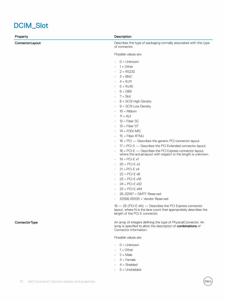
DCIM_SlotProperty Description
ConnectorLayout Describes the type of packaging normally associated with this type of connector.
Possible values are:
• 0 = Unknown
• 1 = Other
• 2 = RS232
• 3 = BNC
• 4 = RJ11
• 5 = RJ45
• 6 = DB9
• 7 = Slot
• 8 = SCSI High Density
• 9 = SCSI Low Density
• 10 = Ribbon
• 11 = AUI
• 12 = Fiber SC
• 13 = Fiber ST
• 14 = FDDI-MIC
• 15 = Fiber-RTMJ
• 16 = PCI — Describes the generic PCI connector layout.
• 17 = PCI-X — Describes the PCI Extended connector layout.
• 18 = PCI-E — Describes the PCI Express connector layout, where the actual layout with respect to the length is unknown.
• 19 = PCI-E x1
• 20 = PCI-E x2
• 21 = PCI-E x4
• 22 = PCI-E x8
• 23 = PCI-E x16
• 24 = PCI-E x32
• 25 = PCI-E x64
• 26..32567 = DMTF Reserved
• 32568..65535 = Vendor Reserved
19 — 25 (PCI-E xN) — Describes the PCI Express connector layout, where N is the lane count that appropriately describes the length of the PCI-E connector.
ConnectorType An array of integers defining the type of PhysicalConnector. An array is specified to allow the description of combinations of Connector information.
Possible values are:
• 0 = Unknown
• 1 = Other
• 2 = Male
• 3 = Female
• 4 = Shielded
• 5 = Unshielded
70 Dell Command | Monitor classes and properties

Property Description
• 6 = SCSI (A) High-Density (50 pins)
• 7 = SCSI (A) Low-Density (50 pins)
• 8 = SCSI (P) High-Density (68 pins)
• 9 = SCSI SCA-I (80 pins)
• 10 = SCSI SCA-II (80 pins)
• 11 = Fibre Channel (DB-9, Copper)
• 12 = Fibre Channel (Optical Fibre)
• 13 = Fibre Channel SCA-II (40 pins)
• 14 = Fibre Channel SCA-II (20 pins)
• 15 = Fibre Channel BNC
• 16 = ATA 3-1/2 Inch (40 pins)
• 17 = ATA 2-1/2 Inch (44 pins)
• 18 = ATA-2
• 19 = ATA-3
• 20 = ATA/66
• 21 = DB-9
• 22 = DB-15
• 23 = DB-25
• 24 = DB-36
• 25 = RS-232C
• 26 = RS-422
• 27 = RS-423
• 28 = RS-485
• 29 = RS-449
• 30 = V.35
• 31 = X.21
• 32 = IEEE-488
• 33 = AUI
• 34 = UPT Category 3
• 35 = UPT Category 4
• 36 = UPT Category 5
• 37 = BNC
• 38 = RJ11
• 39 = RJ45
• 40 = Fiber MIC
• 41 = Apple AUI
• 42 = Apple GeoPort
• 43 = PCI
• 44 = ISA
• 45 = EISA
• 46 = VESA
• 47 = PCMCIA
• 48 = PCMCIA Type I
• 49 = PCMCIA Type II
• 50 = PCMCIA Type III
• 51 = ZV Port
• 52 = CardBus
• 53 = USB
• 54 = IEEE 1394
• 55 = HIPPI
Dell Command | Monitor classes and properties 71

Property Description
• 56 = HSSDC (6 pins)
• 57 = GBIC
• 58 = DIN
• 59 = Mini-DIN
• 60 = Micro-DIN
• 61 = PS/2
• 62 = Infrared
• 63 = HP-HIL
• 64 = Access.bus
• 65 = NuBus
• 66 = Centronics
• 67 = Mini-Centronics
• 68 = Mini-Centronics Type-14
• 69 = Mini-Centronics Type-20
• 70 = Mini-Centronics Type-26
• 71 = Bus Mouse
• 72 = ADB
• 73 = AGP
• 74 = VME Bus
• 75 = VME64
• 76 = Proprietary
• 77 = Proprietary Processor Card Slot
• 78 = Proprietary Memory Card Slot
• 79 = Proprietary I/O Riser Slot
• 80 = PCI-66MHZ
• 81 = AGP2X
• 82 = AGP4X
• 83 = PC-98
• 84 = PC-98-Hireso
• 85 = PC-H98
• 86 = PC-98Note
• 87 = PC-98Full
• 88 = SSA SCSI
• 89 = Circular
• 90 = On Board IDE Connector
• 91 = On Board Floppy Connector
• 92 = 9 Pin Dual Inline
• 93 = 25 Pin Dual Inline
• 94 = 50 Pin Dual Inline
• 95 = 68 Pin Dual Inline
• 96 = On Board Sound Connector
• 97 = Mini-jack
• 98 = PCI-X
• 99 = Sbus IEEE 1396-1993 32 bit
• 100 = Sbus IEEE 1396-1993 64 bit
• 101 = MCA
• 102 = GIO
• 103 = XIO
• 104 = HIO
• 105 = NGIO
72 Dell Command | Monitor classes and properties

Property Description
• 106 = PMC
• 107 = MTRJ
• 108 = VF-45
• 109 = Future I/O
• 110 = SC
• 111 = SG
• 112 = Electrical
• 113 = Optical
• 114 = Ribbon
• 115 = GLM
• 116 = 1x9
• 117 = Mini SG
• 118 = LC
• 119 = HSSC
• 120 = VHDCI Shielded (68 pins)
• 121 = InfiniBand
• 122 = AGP8X
For example, one array entry could specify RS-232 (value = 25), another DB-25 (value = 23) and a third entry define the Connector as Male (value = 2). This single property is being deprecated instead of using separate properties to describe the various aspects of the connector. The separation allows for a more generic means of describing the connectors. Obsolete connectors were intentionally removed from the new list.
CreationClassName Indicates the name of the class or the subclass used in the creation of an instance. When used with the other key properties of this class, this property allows all instances of this class and its subclasses to be uniquely identified.
ElementName A user-friendly name for the object. This property allows each instance to define a user-friendly name in addition to its key properties, identity data, and description information.
NOTE: The Name property of ManagedSystemElement is also defined as a user-friendly name. But, it is often sub-classed to be a Key. It is not reasonable that the same property can convey both identity and a user-friendly name, without inconsistencies. Where Name exists and is not a Key (such as for instances of LogicalDevice), the same information can be present in both the Name and ElementName properties.
Number The Number property indicates the physical slot number, which can be used as an index into a system slot table, whether or not that slot is physically occupied.
SupportsHotPlug Boolean indicating whether the Slot supports hot-plug of adapter Cards.
Tag An arbitrary string that uniquely identifies the Physical Element and serves as the key of the Element. The Tag property can contain information such as asset tag or serial number data. The key for PhysicalElement is placed very high in the object hierarchy to independently identify the hardware or entity, regardless of physical placement in or on Cabinets, Adapters, and so on. For example, a hotswappable or removable component can be taken from its
Dell Command | Monitor classes and properties 73
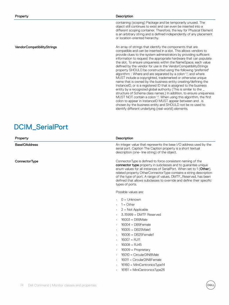
Property Description
containing (scoping) Package and be temporarily unused. The object still continues to exist and can even be inserted into a different scoping container. Therefore, the key for Physical Element is an arbitrary string and is defined independently of any placement or location-oriented hierarchy.
VendorCompatibilityStrings An array of strings that identify the components that are compatible and can be inserted in a slot. This allows vendors to provide clues to the system administrators by providing sufficient information to request the appropriate hardware that can populate the slot. To ensure uniqueness within the NameSpace, each value defined by the vendor for use in the VendorCompatibilityStrings property SHOULD be constructed using the following 'preferred' algorithm: : Where and are separated by a colon ':', and where MUST include a copyrighted, trademarked or otherwise unique name that is owned by the business entity creating/defining the InstanceID, or is a registered ID that is assigned to the business entity by a recognized global authority (This is similar to the _ structure of Schema class names.) In addition, to ensure uniqueness MUST NOT contain a colon ':'. When using this algorithm, the first colon to appear in InstanceID MUST appear between and . is chosen by the business entity and SHOULD not be re-used to identify different underlying (real-world) elements.
DCIM_SerialPortProperty Description
BaseIOAddress An integer value that represents the base I/O address used by the serial port. Caption The Caption property is a short textual description (one- line string) of the object.
ConnectorType ConnectorType is defined to force consistent naming of the connector type property in subclasses and to guarantee unique enum values for all instances of SerialPort. When set to 1 (Other), related property OtherConnectorType contains a string description of the type of port. A range of values, DMTF_Reserved, has been defined that allows subclasses to override and define their specific types of ports.
Possible values are:
• 0 = Unknown
• 1 = Other
• 2 = Not Applicable
• 3..15999 = DMTF Reserved
• 16003 = DB9Male
• 16004 = DB9Female
• 16005 = DB25Male1
• 16006 = DB25Female1
• 16007 = RJ11
• 16008 = RJ45
• 16009 = Proprietary
• 16010 = CircularDIN8Male
• 16011 = CircularDIN8Female
• 16160 = MiniCentronicsType14
• 16161 = MiniCentronicsType26
74 Dell Command | Monitor classes and properties

Property Description
• 16162..65535 = Vendor Reserved
CreationClassName Indicates the name of the class or the subclass used in the creation of an instance. When used with the other key properties of this class, this property allows all instances of this class and its subclasses to be uniquely identified.
DeviceID An address or other identifying information used to uniquely name the LogicalDevice.
ElementName A user-friendly name for the object. This property allows each instance to define a user-friendly name in addition to its key properties, identity data, and description information.
NOTE: The Name property of ManagedSystemElement is also defined as a user-friendly name. But, it is often subclassed to be a Key. It is not reasonable that the same property can convey both identity and a user-friendly name, without inconsistencies. Where Name exists and is not a Key (such as for instances of LogicalDevice), the same information can be present in both the Name and ElementName properties.
EnabledDefault An enumerated value indicating an administrator's default or startup configuration for the Enabled State of an element.
Possible values are:
• 2 = Enabled
• 3 = Disabled
• 5 = Not Applicable
• 6 = Enabled but Offline
• 7 = No Default
• 9 = Quiesce
• .. = DMTF Reserved
• 32768..65535 = Vendor Reserved
By default, the element is Enabled (value = 2).
EnabledState An integer enumeration that indicates the enabled and disabled states of an element. It can also indicate the transitions between these requested states. For example, shutting down (value = 4) and starting (value = 10) are transient states between enabled and disabled.
Possible values are:
• 0 = Unknown
• 1 = Other
• 2 = Enabled — Indicates that the element is or could be executing commands, processes any queued commands, and queues new requests.
• 3 = Disabled — Indicates that the element will not run commands and drops any new requests.
• 4 = Shutting Down — Indicates that the element is in the process of going to a Disabled state.
• 5 = Not Applicable — Indicates that the element does not support being enabled or disabled.
• 6 = Enabled but Offline — Indicates that the element may be completing commands, and drops any new requests.
Dell Command | Monitor classes and properties 75

Property Description
• 7 = In Test — Indicates that the element is in a test state.
• 8 = Deferred — Indicates that the element may be completing commands, but queues any new requests.
• 9 = Quiesce — Indicates that the element is enabled but in a restricted mode.
• 10 = Starting — Indicates that the element is in the process of going to an Enabled state. New requests are queued.
• 11..32767 = DMTF Reserved
• 32768..65535 = Vendor Reserved
HealthState Indicates the current health of the element. This attribute expresses the health of this element but not necessarily that of its subcomponents.
Possible values are:
• 0 = Unknown — The implementation cannot report on HealthState now. DMTF has reserved the unused portion of the continuum for additional HealthStates in the future.
• 5 = OK — The element is fully functional and is operating within normal operational parameters and without error.
• 10 = Degraded/Warning — The element is in working order and all functionality is provided. However, the element is not working to the best of its abilities. For example, the element may not be operating at optimal performance or it may be reporting recoverable errors.
• 15 = Minor failure — All functionality is available but some may be degraded.
• 20 = Major failure — The element is failing. It is possible that some or all of the functionality of this component is degraded or not working.
• 25 = Critical failure — The element is nonfunctional and recovery may not be possible.
• 30 = Non-recoverable error
• .. = DMTF Reserved — The element has failed, and recovery is not possible. All functionality provided by this element has been lost.
IRQLevel An integer value that represents the IRQ level used by the serial port.
MaxSpeed The maximum bandwidth of the Port in Bits per Second.
OperationalStatus Indicates the current statuses of the element. Various operational statuses are defined. Many of the enumeration's values are self-explanatory. However, a few are not and are described here in more detail.
Possible values are:
• 0 = Unknown
• 1 = Other
• 2 = OK
• 3 = Degraded
• 4 = Stressed — Indicates that the element is functioning, but needs attention. Examples of Stressed states are overload, overheated, and so on.
• 5 = Predictive Failure — Indicates that an element is functioning nominally but predicting a failure soon.
• 6 = Error
76 Dell Command | Monitor classes and properties

Property Description
• 7 = Non-Recoverable Error
• 8 = Starting
• 9 = Stopping
• 10 = Stopped — Implies a clean and orderly stop.
• 11 = In Service — Describes an element being configured, maintained, cleaned, or otherwise administered.
• 12 = No Contact — Indicates that the monitoring system has knowledge of this element, but has never been able to establish communications with it.
• 13 = Lost Communication — Indicates that the ManagedSystem Element is known to exist and has been contacted successfully in the past, but is unreachable.
• 14 = Aborted — Implies an abrupt stop where the state and configuration of the element may need to be updated.
• 15 = Dormant — Indicates that the element is inactive or quiesced.
• 16 = Supporting Entity in Error — Indicates that this element may be OK but that another element, on which it is dependent, is in error. An example is a network service or endpoint that cannot function due to lower-layer networking problems.
• 17 = Completed — Indicates that the element has completed its operation. This value should be combined with either OK, Error, or Degraded so that a client can tell if the complete operation Completed with OK (passed), Completed with Error (failed), or Completed with Degraded (the operation finished, but it did not complete OK or did not report an error).
• 18 = Power Mode — Indicates that the element has additional power model information contained in the Associated PowerManagementService association.
• .. = DMTF Reserved
• 0x8000.. = Vendor Reserved
OperationalStatus replaces the Status property on ManagedSystemElement to provide a consistent approach to enumerations, to address implementation needs for an array property, and to provide a migration path from today's environment to the future. This change was not made earlier because it required the deprecated qualifier. Due to the widespread use of the existing Status property in management applications, it is recommended that providers or instrumentation provide both the Status and OperationalStatus properties. Further, the first value of OperationalStatus should contain the primary status for the element. When instrumented, Status (because it is single-valued) should also provide the primary status of the element.
PortType PortType is defined to force consistent naming of the type property in subclasses and to guarantee unique enum values for all instances of NetworkPort. When set to 1 (Other), related property OtherPortType contains a string description of the type of port. A range of values, DMTF_Reserved, has been defined that allows subclasses to override and define their specific types of ports.
Possible values are:
• 0 = Unknown
• 1 = Other
• 2 = Not Applicable
• 3..15999 = DMTF Reserved
• 16192 = Parallel Port
• 16193 = Serial Port
• 16194 = Pointing Device
Dell Command | Monitor classes and properties 77

Property Description
• 16195 = Keyboard
• 16196 = Processor
• 16197 = Memory Device
• 16198 = USB
• 16199 = Monitor
• 16200 = SCSI
• 16201..65535 = Vendor Reserved
PrimaryStatus Provides a high-level status value, intended to align with Red-Yellow-Green type representation of status. It should be used with DetailedStatus to provide high level and detailed health status of the ManagedElement and its subcomponents.
Possible values are:
• 0 = Unknown
• 1 = Other
• 2 = Not Applicable
• 3..15999 = DMTF Reserved
• 16192 = Parallel Port
• 16193 = Serial Port
• 16194 = Pointing Device
• 16195 = Keyboard
• 16196 = Processor
• 16197 = Memory Device
• 16198 = USB
• 16199 = Monitor
• 16200 = SCSI
• 16201..65535 = Vendor Reserved
PrimaryStatus Provides a high-level status value, intended to align with Red-Yellow-Green type representation of status. It should be used with DetailedStatus to provide high level and detailed health status of the ManagedElement and its subcomponents.
Possible values are:
• 0 = Unknown — Indicates that the implementation is in general capable of returning this property, but is unable to do so now.
• 1 = OK — Indicates the ManagedElement is functioning normally.
• 2 = Degraded — Indicates the ManagedElement is functioning below normal.
• 3 = Error — Indicates the ManagedElement is in an Error condition.
• .. = DMTF Reserved
• 0x8000.. = Vendor Reserved
RequestedSpeed The requested bandwidth of the Port in Bits per Second. The actual bandwidth is reported in LogicalPort.Speed.
RequestedState An integer enumeration that indicates the last requested or desired state for the element, irrespective of the mechanism through which it was requested. The actual state of the element is represented by EnabledState. This property is provided to compare the last requested and current enabled or disabled states. When EnabledState is set to 5 (Not Applicable), then this property has no
78 Dell Command | Monitor classes and properties
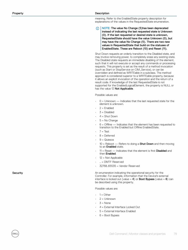
Property Description
meaning. Refer to the EnabledState property description for explanations of the values in the RequestedState enumeration.
NOTE: The value No Change (5)has been deprecated instead of indicating the last requested state is Unknown (0). If the last requested or desired state is unknown, RequestedState should have the value Unknown (0), but may have the value No Change (5). There are two new values in RequestedState that build on the statuses of EnabledState. These are Reboot (10) and Reset (11).
Shut Down requests an orderly transition to the Disabled state, and may involve removing power, to completely erase any existing state. The Disabled state requests an immediate disabling of the element, such that it will not execute or accept any commands or processing requests. This property is set as the result of a method invocation (such as Start or StopService on CIM_Service), or can be overridden and defined as WRITEable in a subclass. The method approach is considered superior to a WRITEable property, because it allows an explicit invocation of the operation and the return of a result code. If knowledge of the last RequestedState is not supported for the EnabledLogicalElement, the property is NULL or has the value 12 Not Applicable.
Possible values are:
• 0 = Unknown — Indicates that the last requested state for the element is unknown.
• 2 = Enabled
• 3 = Disabled
• 4 = Shut Down
• 5 = No Change
• 6 = Offline — Indicates that the element has been requested to transition to the Enabled but Offline EnabledState.
• 7 = Test
• 8 = Deferred
• 9 = Quiesce
• 10 = Reboot — Refers to doing a Shut Down and then moving to an Enabled state.
• 11 = Reset — Indicates that the element is first Disabled and then Enabled.
• 12 = Not Applicable
• .. = DMTF Reserved
• 32768..65535 = Vendor Reserved
Security An enumeration indicating the operational security for the Controller. For example, information that the Device's external interface is locked out (value = 4) or Boot Bypass (value = 6) can be described using this property.
Possible values are:
• 1 = Other
• 2 = Unknown
• 3 = None
• 4 = External Interface Locked Out
• 5 = External Interface Enabled
• 6 = Boot Bypass
Dell Command | Monitor classes and properties 79

Property Description
SerialPortCapabilities The capabilities of this Serial port.
Possible values are:
• 1 = Other
• 2 = Unknown
• 3 = XT/AT compatible
• 4 = 16450 compatible
• 5 = 16550 compatible
• 6 = 16550A compatible
• 160 = 8251 compatible
• 161 = 8251FIFO compatible
SystemCreationClassName The creation class name of the scoping system.
SystemName The system name of the scoping system.
TransitioningToState Indicates the target state to which the instance is transitioning.
Possible values are:
• 0 = Unknown
• 2 = Enabled
• 3 = Disabled
• 4 = Shut Down
• 5 = No Change — Indicates that no transition is in progress.
• 6 = Offline
• 7 = Test
• 8 = Defer
• 9 = Quiesce
• 10 = Reboot
• 11 = Reset
• 12 = Not Applicable — Indicates that the implementation does not support representing ongoing transitions.
A value other than 5 or 12 identifies the state to which the element is in the process of transitioning.
DCIM_USBPortProperty Description
CreationClassName Indicates the name of the class or the subclass used in the creation of an instance. When used with the other key properties of this class, this property allows all instances of this class and its subclasses to be uniquely identified.
DeviceID An address or other identifying information used to uniquely name the LogicalDevice.
ElementName A user-friendly name for the object. This property allows each instance to define a user-friendly name in addition to its key properties, identity data, and description information.
80 Dell Command | Monitor classes and properties

Property Description
NOTE: The Name property of ManagedSystemElement is also defined as a user-friendly name. But, it is often subclassed to be a Key. It is not reasonable that the same property can convey both identity and a user-friendly name, without inconsistencies. Where Name exists and is not a Key (such as for instances of LogicalDevice), the same information can be present in both the Name and ElementName properties.
EnabledDefault An enumerated value indicating a configuration of an administrator for the Enabled State of an element.
Possible values are:
• 2 = Enabled
• 3 = Disabled
• 5 = Not Applicable
• 6 = Enabled but Offline
• 7 = No Default
• 9 = Quiesce
• .. = DMTF Reserved
• 32768..65535 = Vendor Reserved
By default, the element is Enabled (value = 2).
EnabledState An integer enumeration that indicates the enabled and disabled states of an element. It can also indicate the transitions between these requested states.
Possible values are:
• 0 = Unknown
• 1 = Other
• 2 = Enabled — Indicates that the element is or could be running commands, will process any queued commands, and queues new requests.
• 3 = Disabled — Indicates that the element will not run commands and will drop any new requests.
• 4 = Shutting Down — Indicates that the element is in the process of going to a disabled state.
• 5 = Not Applicable — Indicates the element does not support being enabled or disabled.
• 6 = Enabled but Offline — Indicates that the element may be completing commands, and will drop any new requests.
• 7 = In Test — Indicates that the element is in a test state.
• 8 = Deferred — Indicates that the element may be completing commands, but will queue any new requests.
• 9 = Quiesce — Indicates that the element is enabled but in a restricted mode.
• 10 = Starting — Indicates that the element is in the process of going to an enabled state. New requests are queued.
• 11..32767 = DMTF Reserved
• 32768..65535 = Vendor Reserved
For example, shutting down (value = 4) and starting (value = 10) are transient states between enabled and disabled.
Dell Command | Monitor classes and properties 81
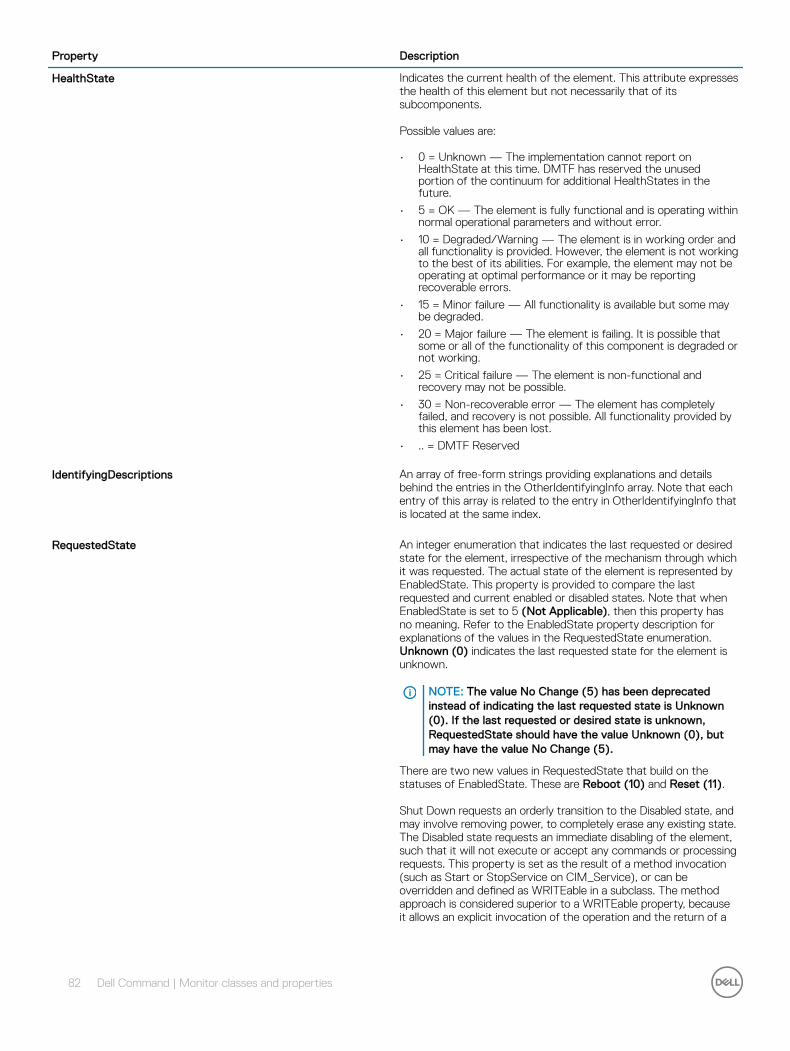
Property Description
HealthState Indicates the current health of the element. This attribute expresses the health of this element but not necessarily that of its subcomponents.
Possible values are:
• 0 = Unknown — The implementation cannot report on HealthState at this time. DMTF has reserved the unused portion of the continuum for additional HealthStates in the future.
• 5 = OK — The element is fully functional and is operating within normal operational parameters and without error.
• 10 = Degraded/Warning — The element is in working order and all functionality is provided. However, the element is not working to the best of its abilities. For example, the element may not be operating at optimal performance or it may be reporting recoverable errors.
• 15 = Minor failure — All functionality is available but some may be degraded.
• 20 = Major failure — The element is failing. It is possible that some or all of the functionality of this component is degraded or not working.
• 25 = Critical failure — The element is non-functional and recovery may not be possible.
• 30 = Non-recoverable error — The element has completely failed, and recovery is not possible. All functionality provided by this element has been lost.
• .. = DMTF Reserved
IdentifyingDescriptions An array of free-form strings providing explanations and details behind the entries in the OtherIdentifyingInfo array. Note that each entry of this array is related to the entry in OtherIdentifyingInfo that is located at the same index.
RequestedState An integer enumeration that indicates the last requested or desired state for the element, irrespective of the mechanism through which it was requested. The actual state of the element is represented by EnabledState. This property is provided to compare the last requested and current enabled or disabled states. Note that when EnabledState is set to 5 (Not Applicable), then this property has no meaning. Refer to the EnabledState property description for explanations of the values in the RequestedState enumeration. Unknown (0) indicates the last requested state for the element is unknown.
NOTE: The value No Change (5) has been deprecated instead of indicating the last requested state is Unknown (0). If the last requested or desired state is unknown, RequestedState should have the value Unknown (0), but may have the value No Change (5).
There are two new values in RequestedState that build on the statuses of EnabledState. These are Reboot (10) and Reset (11).
Shut Down requests an orderly transition to the Disabled state, and may involve removing power, to completely erase any existing state. The Disabled state requests an immediate disabling of the element, such that it will not execute or accept any commands or processing requests. This property is set as the result of a method invocation (such as Start or StopService on CIM_Service), or can be overridden and defined as WRITEable in a subclass. The method approach is considered superior to a WRITEable property, because it allows an explicit invocation of the operation and the return of a
82 Dell Command | Monitor classes and properties

Property Description
result code. If knowledge of the last RequestedState is not supported for the EnabledLogicalElement, the property is NULL or has the value 12 Not Applicable.
Possible values are:
• 0 = Unknown
• 2 = Enabled
• 3 = Disabled
• 4 = Shut Down
• 5 = No Change
• 6 = Offline — Indicates that the element has been requested to transition to the Enabled but Offline EnabledState.
• 7 = Test
• 8 = Deferred
• 9 = Quiesce
• 10 = Reboot — Refers to doing a Shut Down and then moving to an Enabled state.
• 11 = Reset — Indicates that the element is first Disabled and then Enabled.
• 12 = Not Applicable
• .. = DMTF Reserved
• 32768..65535 = Vendor Reserved
Speed USB Port Speed in bits per second. This speed is determined and set by the attached Device. The attached Device is indicated using the USBConnection association. At this time, only several Port speeds are valid. These are: 1.5Mbps and 12Mbps. The value 0 can also be specified to indicate that the current speed is unknown or 1 to indicate that the speed is other than 1.5 or 12Mbps. Possible values are: 0, 1, 1500000, 12000000
SystemCreationClassName The CreationClassName of the scoping system.
SystemName The System Name of the scoping system.
TransitioningToState Indicates the target state to which the instance is transitioning.
Possible values are:
• 0 = Unknown
• 2 = Enabled
• 3 = Disabled
• 4 = Shut Down
• 5 = No Change — Indicates that no transition is in progress.
• 6 = Offline
• 7 = Test
• 8 = Defer
• 9 = Quiesce
• 10 = Reboot
• 11 = Reset
• 12 = Not Applicable — Indicates the implementation does not support representing ongoing transitions.
A value other than 5 or 12 identifies the state to which the element is in the process of transitioning.
Dell Command | Monitor classes and properties 83
DCIM_MemoryProperty Description
Access Access describes whether the media is readable (value = 1), writeable (value = 2), or both (value = 3). Unknown (0) and Write Once (4) can also be defined.
Possible values are:
• 0 = Unknown
• 1 = Readable
• 2 = Writeable
• 3 = Read/Write Supported
• 4 = Write Once
BlockSize Size in bytes of the blocks which form this StorageExtent. If variable block size, then the maximum block size in bytes should be specified. If the block size is unknown or if a block concept is not valid (for example, for AggregateExtents, Memory or LogicalDisks), enter a 1.
ConsumableBlocks The maximum number of blocks, of size BlockSize, which are available for consumption when layering StorageExtents using the BasedOn association. This property only has meaning when this StorageExtent is an Antecedent reference in a BasedOn relationship. For example, a StorageExtent could be composed of 120 blocks. However, the Extent itself may use 20 blocks for redundancy data. If another StorageExtent is BasedOn this Extent, only 100 blocks would be available to it. This information (100 blocks is available for consumption) is indicated in the ConsumableBlocks property.
CreationClassName Indicates the name of the class or the subclass used in the creation of an instance. When used with the other key properties of this class, this property allows all instances of this class and its subclasses to be uniquely identified.
DeviceID An address or other identifying information used to uniquely name the LogicalDevice.
ElementName A user-friendly name for the object. This property allows each instance to define a user-friendly name in addition to its key properties, identity data, and description information.
NOTE: The Name property of ManagedSystemElement is also defined as a user-friendly name. But, it is often subclassed to be a Key. It is not reasonable that the same property can convey both identity and a user-friendly name, without inconsistencies. Where Name exists and is not a Key (such as for instances of LogicalDevice), the same information can be present in both the Name and ElementName properties.
EnabledDefault An enumerated value indicating an administrator's default or startup configuration for the Enabled State of an element.
Possible values are:
• 2 = Enabled
• 3 = Disabled
84 Dell Command | Monitor classes and properties

Property Description
• 5 = Not Applicable
• 6 = Enabled but Offline
• 7 = No Default
• 9 = Quiesce
• .. = DMTF Reserved
• 32768..65535 = Vendor Reserved
EnabledState An integer enumeration that indicates the enabled and disabled states of an element. It can also indicate the transitions between these requested states. For example, shutting down (value = 4) and starting (value = 10) are transient states between enabled and disabled.
Possible values are:
• 0 = Unknown
• 1 = Other
• 2 = Enabled — Indicates that the element is or could be executing commands, will process any queued commands, and queues new requests.
• 3 = Disabled — Indicates that the element will not execute commands and will drop any new requests.
• 4 = Shutting Down — Indicates that the element is in the process of going to a Disabled state.
• 5 = Not Applicable — Indicates the element does not support being enabled or disabled.
• 6 = Enabled but Offline — Indicates that the element may be completing commands, and will drop any new requests.
• 7 = In Test — Indicates that the element is in a test state.
• 8 = Deferred — Indicates that the element may be completing commands, but will queue any new requests.
• 9 = Quiesce — Indicates that the element is enabled but in a restricted mode.
• 10 = Starting — Indicates that the element is in the process of going to an Enabled state. New requests are queued.
• 11..32767 = DMTF Reserved
• 32768..65535 = Vendor Reserved
ErrorMethodology ErrorMethodology for Memory is a string property that indicates whether parity or CRC algorithms, ECC or other mechanisms are used. Details on the algorithm can also be supplied.
FailOverState An integer enumeration indicating that active memory has failed and the spare or backup memory may have taken over.
Possible values are:
• 0 = Unknown
• 1 = Other
• 2 = None
• 3 = Active
HealthState Indicates the current health of the element. This attribute expresses the health of this element but not necessarily that of its subcomponents.
Dell Command | Monitor classes and properties 85

Property Description
Possible values are:
• 0 = Unknown — The implementation cannot report on HealthState at this time. DMTF has reserved the unused portion of the continuum for additional HealthStates in the future.
• 5 = OK — The element is fully functional and is operating within normal operational parameters and without error.
• 10 = Degraded/Warning — The element is in working order and all functionality is provided. However, the element is not working to the best of its abilities. For example, the element may not be operating at optimal performance or it may be reporting recoverable errors.
• 15 = Minor failure — All functionality is available but some may be degraded.
• 20 = Major failure — The element is failing. It is possible that some or all of the functionality of this component is degraded or not working.
• 25 = Critical failure — The element is non-functional and recovery may not be possible.
• 30 = Non-recoverable error — The element has completely failed, and recovery is not possible. All functionality provided by this element has been lost.
• .. = DMTF Reserved
NumberOfBlocks Total number of logically contiguous blocks, of size Block Size, which form this Extent. The total size of the Extent can be calculated by multiplying BlockSize by NumberOfBlocks. If the BlockSize is 1, this property is the total size of the Extent.
OperationalStatus Indicates the current statuses of the element. Various operational statuses are defined. Many of the enumeration's values are self-explanatory.
Possible values are:
• 0 = Unknown
• 1 = Other
• 2 = OK
• 3 = Degraded
• 4 = Stressed — Indicates that the element is functioning, but needs attention. Examples of Stressed states are overload, overheated, and so on.
• 5 = Predictive Failure — Indicates that an element is functioning nominally but predicting a failure in the near future.
• 6 = Error
• 7 = Non-Recoverable Error
• 8 = Starting
• 9 = Stopping
• 10 = Stopped
• 11 = In Service — Describes an element being configured, maintained, cleaned, or otherwise administered.
• 12 = No Contact — Indicates that the monitoring system has knowledge of this element, but has never been able to establish communications with it.
• 13 = Lost Communication — Indicates that the ManagedSystem Element is known to exist and has been contacted successfully in the past, but is currently unreachable.
• 14 = Aborted
• 15 = Dormant — Indicates that the element is inactive or quiesced.
86 Dell Command | Monitor classes and properties
Property Description
• 16 = Supporting Entity in Error — Indicates that this element may be OK but that another element, on which it is dependent, is in error. An example is a network service or endpoint that cannot function due to lower-layer networking problems.
• 17 = Completed — Indicates that the element has completed its operation. This value should be combined with either OK, Error, or Degraded so that a client can tell if the complete operation Completed with OK (passed), Completed with Error (failed), or Completed with Degraded (the operation finished, but it did not complete OK or did not report an error).
• 18 = Power Mode — Indicates that the element has additional power model information contained in the Associated PowerManagementService association.
• .. = DMTF Reserved
• 0x8000.. = Vendor Reserved
OperationalStatus replaces the Status property on ManagedSystemElement to provide a consistent approach to enumerations, to address implementation needs for an array property, and to provide a migration path from today's environment to the future. This change was not made earlier because it required the deprecated qualifier. Due to the widespread use of the existing Status property in management applications, it is strongly recommended that providers or instrumentation provide both the Status and OperationalStatus properties. Further, the first value of OperationalStatus should contain the primary status for the element. When instrumented, Status (because it is single-valued) should also provide the primary status of the element.
OtherIdentifyingInfo Captures data, in addition to DeviceID information, that could be used to identify a LogicalDevice. For example, you could use this property to hold the operating system's user-friendly name for the Device.
PrimaryStatus Provides a high level status value, intended to align with Red-Yellow-Green type representation of status. It should be used in conjunction with DetailedStatus to provide high level and detailed health status of the ManagedElement and its subcomponents.
Possible values are:
• 0 = Unknown — Indicates the implementation is in general capable of returning this property, but is unable to do so at this time.
• 1 = OK — Indicates the ManagedElement is functioning normally.
• 2 = Degraded — Indicates the ManagedElement is functioning below normal.
• 3 = Error — Indicates the ManagedElement is in an Error condition.
• .. = DMTF Reserved
• 0x8000.. = Vendor Reserved
Primordial If true, Primordial indicates that the containing System does not have the ability to create or delete this operational element. This is important because StorageExtents are assembled into higher-level abstractions using the BasedOn association. Although the higher-level abstractions can be created and deleted, the most basic, (that is, primordial), hardware-based storage entities cannot. They are physically realized as part of the System, or are actually managed by some other System and imported as if they were physically realized. In other words, a Primordial StorageExtent exists in, but is not
Dell Command | Monitor classes and properties 87
Property Description
created by its System and conversely a non-Primordial StorageExtent is created in the context of its System. For StorageVolumes, this property will generally be false. One use of this property is to enable algorithms that aggregate StorageExtent. ConsumableSpace across all, StorageExtents but that also want to distinquish the space that underlies Primordial StoragePools. Since implementations are not required to surface all Component StorageExtents of a StoragePool, this information is not accessible in any other way. Purpose A free form string describing the media and/or its use. RedundancyConfiguration is an integer enumeration indicating the redundancy configuration when active memory fails.
Possible values are:
• 0 = Unknown
• 1 = Other
• 2 = Disabled
• 3 = Spared
• 4 = Mirrored
• 5 = LockStep
RequestedState An integer enumeration that indicates the last requested or desired state for the element, irrespective of the mechanism through which it was requested. The actual state of the element is represented by EnabledState. This property is provided to compare the last requested and current enabled or disabled states.
NOTE: When EnabledState is set to 5 (Not Applicable), then this property has no meaning. Refer to the EnabledState property description for explanations of the values in the RequestedState enumeration.
NOTE: The value No Change (5) has been deprecated instead of indicating the last requested state is Unknown (0). If the last requested or desired state is unknown, RequestedState should have the value Unknown (0), but may have the value No Change (5).
There are two new values in RequestedState that build on the statuses of EnabledState. These are Reboot (10) and Reset (11). Shut Down requests an orderly transition to the Disabled state, and may involve removing power, to completely erase any existing state. The Disabled state requests an immediate disabling of the element, such that it will not execute or accept any commands or processing requests. This property is set as the result of a method invocation (such as Start or StopService on CIM_Service), or can be overridden and defined as WRITEable in a subclass. The method approach is considered superior to a WRITEable property, because it allows an explicit invocation of the operation and the return of a result code. If knowledge of the last RequestedState is not supported for the EnabledLogicalElement, the property is NULL or has the value 12 (Not Applicable).
Possible values are:
• 0 = Unknown — Indicates the last requested state for the element is unknown.
• 2 = Enabled
• 3 = Disabled
• 4 = Shut Down
• 5 = No Change
• 6 = Offline — Indicates that the element has been requested to transition to the Enabled but Offline EnabledState.
88 Dell Command | Monitor classes and properties
Property Description
• 7 = Test
• 8 = Deferred
• 9 = Quiesce
• 10 = Reboot — Refers to doing a Shut Down and then moving to an Enabled state.
• 11 = Reset - Indicates that the element is first Disabled and then Enabled.
• 12 = Not Applicable
• .. = DMTF Reserved
• 32768..65535 = Vendor Reserved
SystemCreationClassName The CreationClassName of the scoping system.
SystemName The System Name of the scoping system.
TransitioningToState Indicates the target state to which the instance is transitioning.
Possible values are:
• 0 = Unknown
• 2 = Enabled
• 3 = Disabled
• 4 = Shut Down
• 5 = No Change — Indicates that no transition is in progress.
• 6 = Offline
• 7 = Test
• 8 = Defer
• 9 = Quiesce
• 10 = Reboot
• 11 = Reset
• 12 = Not Applicable — Indicates the implementation does not support representing ongoing transitions.
A value other than 5 or 12 identifies the state to which the element is in the process of transitioning.
Volatile Volatile is a property that indicates whether this memory is volatile or not.
DCIM_PCIDeviceProperty Description
BusNumber The bus number where this PCI device resides.
CreationClassName Indicates the name of the class or the subclass used in the creation of an instance. When used with the other key properties of this class, this property allows all instances of this class and its subclasses to be uniquely identified.
Description Provides a textual description of the object.
DeviceID An address or other identifying information used to uniquely name the LogicalDevice.
Dell Command | Monitor classes and properties 89
Property Description
DeviceNumber The device number assigned to this PCI device for this bus.
ElementName A user-friendly name for the object. This property allows each instance to define a user-friendly name in addition to its key properties, identity data, and description information.
NOTE: The Name property of ManagedSystemElement is also defined as a user-friendly name. But, it is often subclassed to be a Key. It is not reasonable that the same property can convey both identity and a user-friendly name, without inconsistencies. Where Name exists and is not a Key (such as for instances of LogicalDevice), the same information can be present in both the Name and ElementName properties.
EnabledDefault An enumerated value indicating an administrator's default or startup configuration for the Enabled State of an element.
Possible values are:
• 2 = Enabled
• 3 = Disabled
• 5 = Not Applicable
• 6 = Enabled but Offline
• 7 = No Default
• 9 = Quiesce
• .. = DMTF Reserved
• 32768..65535 = Vendor Reserved
By default, the element is Enabled (value = 2).
EnabledState A number enumeration that indicates the enabled and disabled states of an element. It can also indicate the transitions between these requested states. For example, shutting down (value = 4) and restarting (value = 10) are temporary states between enabled and disabled.
Possible values are:
• 0 = Unknown
• 1 = Other
• 2 = Enabled — Indicates that the element is or could be executing commands, will process any queued commands, and queues new requests.
• 3 = Disabled — Indicates that the element will not execute commands and will drop any new requests.
• 4 = Shutting Down — Indicates that the element is in the process of going to a Disabled state.
• 5 = Not Applicable — Indicates the element does not support being enabled or disabled.
• 6 = Enabled but Offline — Indicates that the element may be completing commands, and will drop any new requests.
• 7 = In Test — Indicates that the element is in a test state.
• 8 = Deferred — Indicates that the element may be completing commands, but will queue any new requests.
• 9 = Quiesce — Indicates that the element is enabled but in a restricted mode.
• 10 = Starting — Indicates that the element is in the process of going to an Enabled state. New requests are queued.
• 11..32767 = DMTF Reserved
90 Dell Command | Monitor classes and properties

Property Description
• 32768..65535 = Vendor Reserved
FunctionNumber The function number for this PCI device.
HealthState Indicates the current health of the element. This attribute expresses the health of this element but not necessarily that of its subcomponents.
Possible values are:
• 0 = Unknown — The implementation cannot report on HealthState at this time. DMTF has reserved the unused portion of the continuum for additional HealthStates in the future.
• 5 = OK — The element is fully functional and is operating within normal operational parameters and without error.
• 10 = Degraded/Warning — The element is in working order and all functionality is provided. However, the element is not working to the best of its abilities. For example, the element may not be operating at optimal performance or it may be reporting recoverable errors.
• 15 = Minor failure — All functionality is available but some may be degraded.
• 20 = Major failure — The element is failing. It is possible that some or all of the functionality of this component is degraded or not working.
• 25 = Critical failure — The element is non-functional and recovery may not be possible.
• 30 = Non-recoverable error — The element has completely failed, and recovery is not possible. All functionality provided by this element has been lost.
• .. = DMTF Reserved
StatusInfo The use of this method is deprecated instead of a more clearly named property (EnabledState) that is inherited from ManagedSystemElement and that has additional enumerated values. Deprecated description: The StatusInfo property indicates whether the Logical Device is in an enabled state (value = 3), disabled state (value = 4), some other state (value = 1), or an unknown state (value = 2). If this property does not apply to the LogicalDevice, the value 5 (Not Applicable) should be used. If a Device is Enabled (value = 3), it has been powered up and is configured and operational. The Device may or may not be functionally active, depending on whether its Availability (or AdditionalAvailability) indicates that it is Running/Full Power (value = 3) or Off line (value = 8). In an enabled but offline mode, a Device may be performing out-of-band requests, such as running Diagnostics. If StatusInfo is Disabled (value = 4), a Device can only be enabled or powered off. In a personal computer environment, disabled means that the driver of the device is not available in the stack. In other environments, a Device can be disabled by removing its configuration file. A disabled device is physically present in a System and consuming resources, but it cannot be communicated with until a driver is loaded, a configuration file is loaded, or some other enabling activity has occurred.
Possible values are:
• 1 = Other
• 2 = Unknown
• 3 = Enabled
• 4 = Disabled
Dell Command | Monitor classes and properties 91
Property Description
• 5 = Not Applicable
SystemCreationClassName The CreationClassName of the scoping system.
SystemName The System Name of the scoping system.
TransitioningToState Indicates the target state to which the instance is transitioning.
Possible values are:
• 0 = Unknown
• 2 = Enabled
• 3 = Disabled
• 4 = Shut Down
• 5 = No Change — Indicates that no transition is in progress.
• 6 = Offline
• 7 = Test
• 8 = Defer
• 9 = Quiesce
• 10 = Reboot
• 11 = Reset
• 12 = Not Applicable — Indicates the implementation does not support representing ongoing transitions.
A value other than 5 or 12 identifies the state to which the element is in the process of transitioning.
DCIM_DisplayControllerProperty Description
CapabilityDescriptions An array of free-form strings providing more detailed explanations for any of the video Accelerator features indicated in the Capabilities array. Note, each entry of this array is related to the entry in the Capabilities array that is located at the same index.
CommunicationStatus CommunicationStatus indicates the ability of the instrumentation to communicate with the underlying ManagedElement. CommunicationStatus consists of one of the following values: Unknown, None, Communication OK, Lost Communication, or No Contact. A Null return indicates the implementation (provider) does not implement this property.
Possible values are:
• 0 = Unknown — Indicates the implementation is in general capable of returning this property, but is unable to do so at this time.
• 1 = Not Available — Indicates that the implementation (provider) is capable of returning a value for this property, but not ever for this particular piece of hardware/software or the property is intentionally not used because it adds no meaningful information (as in the case of a property that is intended to add additional info to another property).
• 2 = Communication OK — Indicates communication is established with the element, but does not convey any quality of service.
• 3 = Lost Communication — Indicates that the Managed Element is known to exist and has been contacted successfully in the past, but is currently unreachable.
• 4 = No Contact — Indicates that the monitoring system has knowledge of this element, but has never been able to establish communications with it.
• .. = DMTF Reserved
• 0x8000.. = Vendor Reserved
92 Dell Command | Monitor classes and properties

Property Description
CreationClassName Indicates the name of the class or the subclass used in the creation of an instance. When used with the other key properties of this class, this property allows all instances of this class and its subclasses to be uniquely identified.
Description Provides a textual description of the object.
DeviceID An address or other identifying information used to uniquely name the LogicalDevice.
ElementName A user-friendly name for the object. This property allows each instance to define a user-friendly name in addition to its key properties, identity data, and description information.
NOTE: The Name property of ManagedSystemElement is also defined as a user-friendly name. But, it is often subclassed to be a Key. It is not reasonable that the same property can convey both identity and a user-friendly name, without inconsistencies. Where Name exists and is not a Key (such as for instances of LogicalDevice), the same information can be present in both the Name and ElementName properties.
EnabledDefault An enumerated value indicating an administrator's default or startup configuration for the Enabled State of an element. By default, the element is Enabled (value = 2).
Possible values are:
• 2 = Enabled
• 3 = Disabled
• 5 = Not Applicable
• 6 = Enabled but Offline
• 7 = No Default
• 9 = Quiesce
• .. = DMTF Reserved
• 32768..65535 = Vendor Reserved
EnabledState An integer enumeration that indicates the enabled and disabled states of an element. It can also indicate the transitions between these requested states. For example, shutting down (value = 4) and starting (value = 10) are transient states between enabled and disabled.
Possible values are:
• 0 = Unknown
• 1 = Other
• 2 = Enabled — Indicates that the element is or could be executing commands, will process any queued commands, and queues new requests.
• 3 = Disabled — Indicates that the element will not execute commands and will drop any new requests.
• 4 = Shutting Down — Indicates that the element is in the process of going to a Disabled state.
• 5 = Not Applicable — Indicates the element does not support being enabled or disabled.
• 6 = Enabled but Offline — Indicates that the element may be completing commands, and will drop any new requests.
• 7 = In Test — Indicates that the element is in a test state.
• 8 = Deferred — Indicates that the element may be completing commands, but will queue any new requests.
• 9 = Quiesce — Indicates that the element is enabled but in a restricted mode.
• 10 = Starting — Indicates that the element is in the process of going to an Enabled state. New requests are queued.
• 11..32767 = DMTF Reserved
• 32768..65535 = Vendor Reserved
Dell Command | Monitor classes and properties 93

Property Description
Name The Name property defines the label by which the object is known. When subclassed, the Name property can be overridden to be a Key property.
RequestedState An integer enumeration that indicates the last requested or desired state for the element, irrespective of the mechanism through which it was requested. The actual state of the element is represented by EnabledState. This property is provided to compare the last requested and current enabled or disabled states. Note that when EnabledState is set to 5 (Not Applicable), then this property has no meaning. Refer to the EnabledState property description for explanations of the values in the RequestedState enumeration.
NOTE: The value No Change (5) has been deprecated instead of indicating the last requested state is Unknown (0). If the last requested or desired state is unknown, RequestedState should have the value Unknown (0), but may have the value No Change (5). There are two new values in RequestedState that build on the statuses of EnabledState. These are Reboot (10) and Reset (11).
Shut Down requests an orderly transition to the Disabled state, and may involve removing power, to completely erase any existing state. The Disabled state requests an immediate disabling of the element, such that it will not execute or accept any commands or processing requests. This property is set as the result of a method invocation (such as Start or StopService on CIM_Service), or can be overridden and defined as WRITEable in a subclass. The method approach is considered superior to a WRITEable property, because it allows an explicit invocation of the operation and the return of a result code. If knowledge of the last RequestedState is not supported for the EnabledLogicalElement, the property is NULL or has the value 12 Not Applicable.
Possible values are:
• 0 = Unknown — Indicates the last requested state for the element is unknown.
• 2 = Enabled
• 3 = Disabled
• 4 = Shut Down
• 5 = No Change
• 6 = Offline — Indicates that the element has been requested to transition to the Enabled but Offline EnabledState.
• 7 = Test
• 8 = Deferred
• 9 = Quiesce
• 10 = Reboot — Refers to doing a Shut Down and then moving to an Enabled state.
• 11 = Reset — Indicates that the element is first Disabled and then Enabled.
• 12 = Not Applicable
• .. = DMTF Reserved
• 32768..65535 = Vendor Reserved
SystemCreationClassName The CreationClassName of the scoping system.
SystemName The System Name of the scoping system.
TransitioningToState Indicates the target state to which the instance is transitioning.
Possible values are:
• 0 = Unknown
• 2 = Enabled
• 3 = Disabled
• 4 = Shut Down
• 5 = No Change — Indicates that no transition is in progress.
• 6 = Offline
• 7 = Test
94 Dell Command | Monitor classes and properties

Property Description
• 8 = Defer
• 9 = Quiesce
• 10 = Reboot
• 11 = Reset
• 12 = Not Applicable — Indicates the implementation does not support representing ongoing transitions.
A value other than 5 or 12 identifies the state to which the element is in the process of transitioning.
DCIM_FanProperty Description
ActiveCooling ActiveCooling is a Boolean that indicates that the Cooling Device provides active (as opposed to passive) cooling.
CreationClassName Indicates the name of the class or the subclass used in the creation of an instance. When used with the other key properties of this class, this property allows all instances of this class and its subclasses to be uniquely identified.
DeviceID An address or other identifying information used to uniquely name the LogicalDevice.
ElementName A user-friendly name for the object. This property allows each instance to define a user-friendly name in addition to its key properties, identity data, and description information.
NOTE: The Name property of ManagedSystemElement is also defined as a user-friendly name. But, it is often subclassed to be a Key. It is not reasonable that the same property can convey both identity and a user-friendly name, without inconsistencies. Where Name exists and is not a Key (such as for instances of LogicalDevice), the same information can be present in both the Name and ElementName properties.
EnabledDefault An enumerated value indicating an administrator's default or startup configuration for the Enabled State of an element.
Possible values are:
• 2 = Enabled
• 3 = Disabled
• 5 = Not Applicable
• 6 = Enabled but Offline
• 7 = No Default
• 9 = Quiesce
• .. = DMTF Reserved
• 32768..65535 = Vendor Reserved
By default, the element is Enabled (value = 2).
EnabledState An integer enumeration that indicates the enabled and disabled states of an element. It can also indicate the transitions between these requested states. For example, shutting down (value = 4) and starting (value = 10) are transient states between enabled and disabled.
Possible values are:
• 0 = Unknown
• 1 = Other
Dell Command | Monitor classes and properties 95
Property Description
• 2 = Enabled — Indicates that the element is or could be executing commands, will process any queued commands, and queues new requests.
• 3 = Disabled — Indicates that the element will not execute commands and will drop any new requests.
• 4 = Shutting Down — Indicates that the element is in the process of going to a Disabled state.
• 5 = Not Applicable — Indicates the element does not support being enabled or disabled.
• 6 = Enabled but Offline — Indicates that the element may be completing commands, and will drop any new requests.
• 7 = In Test — Indicates that the element is in a test state.
• 8 = Deferred — Indicates that the element may be completing commands, but will queue any new requests.
• 9 = Quiesce - Indicates that the element is enabled but in a restricted mode.
• 10 = Starting - Indicates that the element is in the process of going to an Enabled state. New requests are queued.
• 11..32767 = DMTF Reserved
• 32768..65535 = Vendor Reserved
ErrorCleared The use of this method is deprecated. Deprecated description: ErrorCleared is a Boolean property that indicates that the error reported in LastErrorCode is now cleared.
ErrorDescription The use of this method is deprecated. Deprecated description: ErrorDescription is a free-form string that supplies more information about the error recorded in LastErrorCode and information on any corrective actions that can be taken.
HealthState Indicates the current health of the element. This attribute expresses the health of this element but not necessarily that of its subcomponents.
Possible values are:
• 0 = Unknown — The implementation cannot report on HealthState at this time. DMTF has reserved the unused portion of the continuum for additional HealthStates in the future.
• 5 = OK — The element is fully functional and is operating within normal operational parameters and without error.
• 10 = Degraded/Warning — The element is in working order and all functionality is provided. However, the element is not working to the best of its abilities. For example, the element may not be operating at optimal performance or it may be reporting recoverable errors.
• 15 = Minor failure — All functionality is available but some may be degraded.
• 20 = Major failure — The element is failing. It is possible that some or all of the functionality of this component is degraded or not working.
• 25 = Critical failure — The element is non-functional and recovery may not be possible.
• 30 = Non-recoverable error — The element has completely failed, and recovery is not possible. All functionality provided by this element has been lost.
• .. = DMTF Reserved
OperationalStatus Indicates the current statuses of the element. Various operational statuses are defined. Many of the enumeration's values are self-explanatory. However, a few are not and are described here in more detail.
Possible values are:
• 0 = Unknown
• 1 = Other
• 2 = OK
• 3 = Degraded
• 4 = Stressed — Indicates that the element is functioning, but needs attention. Examples of Stressed states are overload, overheated, and so on.
96 Dell Command | Monitor classes and properties

Property Description
• 5 = Predictive Failure — Indicates that an element is functioning nominally but predicting a failure in the near future.
• 6 = Error
• 7 = Non-Recoverable Error
• 8 = Starting
• 9 = Stopping
• 10 = Stopped - Implies a clean and orderly stop.
• 11 = In Service — Describes an element being configured, maintained, cleaned, or otherwise administered.
• 12 = No Contact — Indicates that the monitoring system has knowledge of this element, but has never been able to establish communications with it.
• 13 = Lost Communication — Indicates that the ManagedSystem Element is known to exist and has been contacted successfully in the past, but is currently unreachable.
• 14 = Aborted — Implies an abrupt stop where the state and configuration of the element may need to be updated.
• 15 = Dormant — Indicates that the element is inactive or quiesced.
• 16 = Supporting Entity in Error — Indicates that this element may be OK but that another element, on which it is dependent, is in error. An example is a network service or endpoint that cannot function due to lower-layer networking problems.
• 17 = Completed — Indicates that the element has completed its operation. This value should be combined with either OK, Error, or Degraded so that a client can tell if the complete operation Completed with OK (passed), Completed with Error (failed), or Completed with Degraded (the operation finished, but it did not complete OK or did not report an error).
• 18 = Power Mode — Indicates that the element has additional power model information contained in the Associated PowerManagementService association.
• .. = DMTF Reserved
• 0x8000.. = Vendor Reserved
PrimaryStatus Provides a high level status value, intended to align with Red-Yellow-Green type representation of status. It should be used in conjunction with DetailedStatus to provide high level and detailed health status of the ManagedElement and its subcomponents.
Possible values are:
• 0 = Unknown — Indicates the implementation is in general capable of returning this property, but is unable to do so at this time.
• 1 = OK — Indicates the ManagedElement is functioning normally.
• 2 = Degraded — Indicates the ManagedElement is functioning below normal.
• 3 = Error — Indicates the ManagedElement is in an Error condition.
• .. = DMTF Reserved
• 0x8000.. = Vendor Reserved
•
RequestedState An integer enumeration that indicates the last requested or desired state for the element, irrespective of the mechanism through which it was requested. The actual state of the element is represented by EnabledState. This property is provided to compare the last requested and current enabled or disabled states. Note that when EnabledState is set to 5 (Not Applicable), then this property has no meaning. Refer to the EnabledState property description for explanations of the values in the RequestedState enumeration. Unknown (0) indicates the last requested state for the element is unknown.
Dell Command | Monitor classes and properties 97

Property Description
NOTE: The value No Change (5) has been deprecated instead of indicating the last requested state is Unknown (0). If the last requested or desired state is unknown, RequestedState should have the value Unknown (0), but may have the value No Change (5). Offline (6) indicates that the element has been requested to transition to the Enabled but Offline EnabledState. There are two new values in RequestedState that build on the statuses of EnabledState. These are Reboot (10) and Reset (11). Reboot refers to doing a Shut Down and then moving to an Enabled state. Reset indicates that the element is first Disabled and then Enabled. Shut Down requests an orderly transition to the Disabled state, and may involve removing power, to completely erase any existing state. The Disabled state requests an immediate disabling of the element, such that it will not execute or accept any commands or processing requests.
This property is set as the result of a method invocation (such as Start or StopService on CIM_Service), or can be overridden and defined as WRITEable in a subclass. The method approach is considered superior to a WRITEable property, because it allows an explicit invocation of the operation and the return of a result code.
If knowledge of the last RequestedState is not supported for the EnabledLogicalElement, the property is NULL or has the value 12 (Not Applicable).
Possible values are:
• 0 = Unknown
• 2 = Enabled
• 3 = Disabled
• 4 = Shut Down
• 5 = No Change
• 6 = Offline
• 7 = Test
• 8 = Deferred
• 9 = Quiesce
• 10 = Reboot
• 11 = Reset
• 12 = Not Applicable
• .. = DMTF Reserved
• 32768..65535 = Vendor Reserved
SystemCreationClassName The CreationClassName of the scoping system.
SystemName The System Name of the scoping system.
TransitioningToState Indicates the target state to which the instance is transitioning.
Possible values are:
• 0 = Unknown
• 2 = Enabled
• 3 = Disabled
• 4 = Shut Down
• 5 = No Change — Indicates that no transition is in progress.
• 6 = Offline
• 7 = Test
• 8 = Defer
• 9 = Quiesce
• 10 = Reboot
• 11 = Reset
98 Dell Command | Monitor classes and properties
Property Description
• 12 = Not Applicable — Indicates the implementation does not support representing ongoing transitions.
A value other than 5 or 12 identifies the state to which the element is in the process of transitioning.
VariableSpeed Indication of whether the fan supports variable speeds.
DCIM_IndicatorLEDProperty Description
Color Color This property indicates the current color of the LED. If the value of the ActivationState property is 4 (Off) this property indicates the color of the LED the last time it was lit, or has the value 2 (Not Applicable).
Possible values are:
• 0 = Unknown
• 1 = Other
• 2 = Not Applicable
• 3 = White
• 4 = Red
• 5 = Green
• 6 = Blue
• 7 = Orange
• 8 = Yellow
• 9 = Black
• .. = DMTF Reserved
• 32768..65535 = Vendor Reserved
ControlMode ControlMode indicates the current control mode for the LED.
Possible values are:
• 2 = Automatic — Indicates the state of the LED is being controlled by the management infrastructure.
• 3 = Manual — Indicates the state of the LED is being controlled by a management client.
• 4 = Test — Indicates the LED is in a test mode.
• .. = DMTF Reserved
• 32768..65535 = Vendor Reserved
ControlPattern An LED may exhibit a range of behavior from very simple (ex. solid on) to very complicated (ex. a series of blinks of alternating color and duration). ControlPattern specifies the vendor or standard behavior exhibited by the LED if it cannot be described using one of the standard behaviors listed for the ActivationState property.
If ActivationState has the value 5 (ControlPattern), the ControlPattern property is not NULL.
The value of ControlPattern is constructed using the following preferred algorithm:
<OrgID>::<Pattern>
Dell Command | Monitor classes and properties 99
Property Description
Where <OrgID> and < Pattern> are separated by two colons (::), and where <OrgID> includes a copyrighted, trademarked, or otherwise unique name that is owned by the business entity that is creating or defining the ControlPattern or that is a registered ID assigned to the business entity by a recognized global authority. If the definition of the value is specified by the DMTF, the value of <OrgID> is DMTF. <Pattern> is chosen by the business entity and is not reused to identify different underlying (real-world) behaviors. If the behavior specified for the LED adheres to a standard or proprietary specification, <Pattern> is a uniquely assigned value identifying the behavior. If the behavior for the LED is described using a standard or proprietary grammar, <Pattern> is prefixed with a uniquely assigned identifier for the grammar.
CreationClassName Indicates the name of the class or the subclass used in the creation of an instance. When used with the other key properties of this class, this property allows all instances of this class and its subclasses to be uniquely identified.
DefaultActivationState Indicates the default state of an LED. See ActivationState for a description of the values.
Possible values are:
• 2 = Lit
• 3 = Blinking
• 4 = Off
• 5 = Control Pattern
• .. = DMTF Reserved
• 32768..65535 = Vendor Reserved
DeviceID An address or other identifying information used to uniquely name the LogicalDevice.
ElementName Specifies an identifier for the LED. The value of ElementName is constructed using the following preferred algorithm:
<OrgID>::<LocalID>
Where <OrgID> and <LocalID> are separated by two colons (::), and where <OrgID> includes a copyrighted, trademarked, or otherwise unique name that is owned by the business entity that is creating or defining the ControlPattern or that is a registered ID assigned to the business entity by a recognized global authority. <LocalID> is chosen by the business entity and should not be reused to identify different underlying (real-world) elements.
EnabledDefault An enumerated value indicating an administrator's default or startup configuration for the Enabled State of an element.
Possible values are:
• 2 = Enabled
• 3 = Disabled
• 5 = Not Applicable
• 6 = Enabled but Offline
• 7 = No Default
• 9 = Quiesce
• .. = DMTF Reserved
• 32768..65535 = Vendor Reserved
By default, the element is Enabled (value = 2).
EnabledState It is an integer enumeration that indicates the enabled and disabled states of an element. It can also indicate the transitions between these requested states. For example, shutting down (value = 4) and starting (value = 10) are transient states between enabled and disabled.
100 Dell Command | Monitor classes and properties

Property Description
Possible values are:
• 0 = Unknown
• 1 = Other
• 2 = Enabled — Indicates that the element is or could be executing commands, will process any queued commands, and queues new requests.
• 3 = Disabled — Indicates that the element will not execute commands and will drop any new requests.
• 4 = Shutting Down — Indicates that the element is in the process of going to a Disabled state.
• 5 = Not Applicable — Indicates the element does not support being enabled or disabled.
• 6 = Enabled but Offline — Indicates that the element may be completing commands, and will drop any new requests.
• 7 = In Test — Indicates that the element is in a test state.
• 8 = Deferred — Indicates that the element may be completing commands, but will queue any new requests.
• 9 = Quiesce — Indicates that the element is enabled but in a restricted mode.
• 10 = Starting — Indicates that the element is in the process of going to an Enabled state. New requests are queued.
• 11..32767 = DMTF Reserved
• 32768..65535 = Vendor Reserved
HealthState Indicates the current health of the element. This attribute expresses the health of this element but not necessarily that of its subcomponents.
Possible values are:
• 0 = Unknown — The implementation cannot report on HealthState at this time.
• 5 = OK — The element is fully functional and is operating within normal operational parameters and without error.
• 10 = Degraded/Warning — The element is in working order and all functionality is provided. However, the element is not working to the best of its abilities. For example, the element may not be operating at optimal performance or it may be reporting recoverable errors.
• 15 = Minor failure — All functionality is available but some may be degraded.
• 20 = Major failure — The element is failing. It is possible that some or all of the functionality of this component is degraded or not working.
• 25 = Critical failure — The element is non-functional and recovery may not be possible.
• 30 = Non-recoverable error — The element has completely failed, and recovery is not possible. All functionality provided by this element has been lost.
• .. = DMTF Reserved
SystemCreationClassName The CreationClassName of the scoping system.
SystemName The System Name of the scoping system.
TransitioningToState Indicates the target state to which the instance is transitioning.
Possible values are:
• 0 = Unknown
• 2 = Enabled
• 3 = Disabled
• 4 = Shut Down
• 5 = No Change — Indicates that no transition is in progress.
• 6 = Offline
• 7 = Test
• 8 = Defer
Dell Command | Monitor classes and properties 101
Property Description
• 9 = Quiesce
• 10 = Reboot
• 11 = Reset
• 12 = Not Applicable — Indicates the implementation does not support representing ongoing transitions.
A value other than 5 or 12 identifies the state to which the element is in the process of transitioning.
DCIM_PowerSupplyProperty Description
CreationClassName Indicates the name of the class or the subclass used in the creation of an instance. When used with the other key properties of this class, this property allows all instances of this class and its subclasses to be uniquely identified.
DeviceID An address or other identifying information used to uniquely name the LogicalDevice.
ElementName A user-friendly name for the object. This property allows each instance to define a user-friendly name in addition to its key properties, identity data, and description information.
NOTE: The Name property of ManagedSystemElement is also defined as a user-friendly name. But, it is often subclassed to be a Key. It is not reasonable that the same property can convey both identity and a user-friendly name, without inconsistencies. Where Name exists and is not a Key (such as for instances of LogicalDevice), the same information can be present in both the Name and ElementName properties.
EnabledDefault An enumerated value indicating an administrator's default or startup configuration for the Enabled State of an element.
Possible values are:
• 2 = Enabled
• 3 = Disabled
• 5 = Not Applicable
• 6 = Enabled but Offline
• 7 = No Default
• 9 = Quiesce
• .. = DMTF Reserved
• 32768..65535 = Vendor Reserved
By default, the element is Enabled (value = 2).
EnabledState An integer enumeration that indicates the enabled and disabled states of an element. It can also indicate the transitions between these requested states.
Possible values are:
• 0 = Unknown
• 1 = Other
• 2 = Enabled — Indicates that the element is or could be executing commands, processes any queued commands, and queues new requests.
• 3 = Disabled — Indicates that the element will not run commands and drops any new requests.
102 Dell Command | Monitor classes and properties

Property Description
• 4 = Shutting Down — Indicates that the element is in the process of going to a Disabled state.
• 5 = Not Applicable — Indicates that the element does not support being enabled or disabled.
• 6 = Enabled but Offline — Indicates that the element may be completing commands, and drops any new requests.
• 7 = In Test — Indicates that the element is in a test state.
• 8 = Deferred — Indicates that the element may be completing commands, but queues any new requests.
• 9 = Quiesce — Indicates that the element is enabled but in a restricted mode.
• 10 = Starting — Indicates that the element is in the process of going to an Enabled state. New requests are queued.
• 11..32767 = DMTF Reserved
• 32768..65535 = Vendor Reserved
For example, shutting down (value = 4) and starting (value = 10) are transient states between enabled and disabled.
HealthState Indicates the current health of the element. This attribute expresses the health of this element but not necessarily that of its subcomponents.
Possible values are:
• 0 = Unknown — The implementation cannot report on HealthState now.
• 5 = OK — The element is fully functional and is operating within normal operational parameters and without error.
• 10 = Degraded/Warning — The element is in working order and all functionality is provided. However, the element is not working to the best of its abilities. For example, the element may not be operating at optimal performance or it may be reporting recoverable errors.
• 15 = Minor failure — All functionality is available but some may be degraded.
• 20 = Major failure — The element is failing. It is possible that some or all of the functionality of this component is degraded or not working.
• 25 = Critical failure — The element is nonfunctional and recovery may not be possible.
• 30 = Non-recoverable error — The element has completely failed, and recovery is not possible. All functionality provided by this element has been lost.
• .. = DMTF Reserved
DMTF has reserved the unused portion of the continuum for additional HealthStates in the future.
RequestedState An integer enumeration that indicates the last requested or desired state for the element, irrespective of the mechanism through which it was requested.
Possible values are:
• 0 = Unknown — Indicates that the last requested state for the element is unknown.
• 2 = Enabled — Indicates that the element is or could be executing commands, will process any queued commands, and queues new requests.
• 3 = Disabled — Requests an immediate disabling of the element, such that it will not run or accept any commands or processing requests.
• 4 = Shut Down — Requests an orderly transition to the Disabled state, and may involve removing power, to completely erase any existing state.
• 5 = No Change
• 6 = Offline — Indicates that the element has been requested to transition to the Enabled but Offline EnabledState.
• 7 = Test
• 8 = Deferred
• 9 = Quiesce
Dell Command | Monitor classes and properties 103

Property Description
• 10 = Reboot — Refers to doing a Shut Down and then moving to an Enabled state.
• 11 = Reset — Indicates that the element is first Disabled and then Enabled.
• 12 = Not Applicable
• .. = DMTF Reserved
• 32768..65535 = Vendor Reserved
The actual state of the element is represented by EnabledState. This property is provided to compare the last requested and current enabled or disabled states. Note that when EnabledState is set to 5 (Not Applicable), then this property has no meaning. Refer to the EnabledState property description for explanations of the values in the RequestedState enumeration.
NOTE: The value No Change (5) has been deprecated instead of indicating the last requested state is Unknown (0). If the last requested or desired state is unknown, RequestedState should have the value Unknown (0), but may have the value No Change (5).
There are two new values in RequestedState that build on the statuses of EnabledState. These are Reboot (10) and Reset (11). This property is set as the result of a method invocation (such as Start or StopService on CIM_Service), or can be overridden and defined as WRITEable in a subclass. The method approach is considered superior to a WRITEable property, because it allows an explicit invocation of the operation and the return of a result code.
If knowledge of the last RequestedState is not supported for the EnabledLogicalElement, the property is NULL or has the value 12 Not Applicable.
SystemCreationClassName The CreationClassName of the scoping system.
SystemName The System Name of the scoping system.
TotalOutputPower Represents the total output power of the PowerSupply in milli Watts. 0 denotes unknown.
TransitioningToState Indicates the target state to which the instance is transitioning.
Possible values are:
• 0 = Unknown
• 2 = Enabled
• 3 = Disabled
• 4 = Shut Down
• 5 = No Change — Indicates that no transition is in progress.
• 6 = Offline
• 7 = Test
• 8 = Defer
• 9 = Quiesce
• 10 = Reboot
• 11 = Reset
• 12 = Not Applicable — Indicates that the implementation does not support representing ongoing transitions.
A value other than 5 or 12 identifies the state to which the element is in the process of transitioning.
TypeOfRangeSwitching Describes the kind of input voltage range switching that is implemented in this PowerSupply.
Possible values are:
• 1 = Other
• 2 = Unknown
104 Dell Command | Monitor classes and properties
Property Description
• 3 = Manual
• 4 = Autoswitch
• 5 = Wide Range
• 6 = Not Applicable
A value other than 5 or 12 identifies the state to which the element is in the process of transitioning.
DCIM_BatteryProperty Description
BatteryStatus Description of the charge status of the Battery.
Possible values are:
• 1 = Other
• 2 = Unknown
• 3 = Fully Charged
• 4 = Low
• 5 = Critical
• 6 = Charging
• 7 = Charging and High
• 8 = Charging and Low
• 9 = Charging and Critical
• 10 = Undefined
• 11 = Partially Charged
• 12 = Learning
• 13 = Overcharged
Values such as Fully Charged (value = 3) or Partially Charged (value = 11) can be specified. The value, 10, is not valid in the CIM Schema because in DMI it represents that no battery is installed. In this case, this object should not be instantiated.
ChargingStatus This property defines status information about the AC line in the notebook.
Possible values are:
• 1 = Other
• 2 = Unknown
• 3 = Off- Line
• 4 = On-Line
• 5 = On Backup Power
Chemistry An enumeration that describes the chemistry of the Battery.
• 1 = Other
• 2 = Unknown
• 3 = Lead Acid
• 4 = Nickel Cadmium
• 5 = Nickel Metal Hydride
• 6 = Lithium-ion
• 7 = Zinc air
Dell Command | Monitor classes and properties 105

Property Description
• 8 = Lithium Polymer
CreationClassName Indicates the name of the class or the subclass used in the creation of an instance. When used with the other key properties of this class, this property allows all instances of this class and its subclasses to be uniquely identified.
DesignCapacity The design capacity of the battery in m Watt-hours. If this property is not supported, enter 0.
DesignVoltage The design voltage of the battery in mVolts. If this attribute is not supported, enter 0.
DeviceID An address or other identifying information used to uniquely name the LogicalDevice.
ElementName A user-friendly name for the object. This property allows each instance to define a user-friendly name in addition to its key properties, identity data, and description information.
NOTE: The Name property of ManagedSystemElement is also defined as a user-friendly name. But, it is often subclassed to be a Key. It is not reasonable that the same property can convey both identity and a user-friendly name, without inconsistencies. Where Name exists and is not a Key (such as for instances of LogicalDevice), the same information can be present in both the Name and ElementName properties.
EnabledDefault An enumerated value indicating an administrator's default or startup configuration for the Enabled State of an element.
Possible values are:
• 2 = Enabled
• 3 = Disabled
• 5 = Not Applicable
• 6 = Enabled but Offline
• 7 = No Default
• 9 = Quiesce
• .. = DMTF Reserved
• 32768..65535 = Vendor Reserved
By default, the element is Enabled (value = 2).
EnabledState An integer enumeration that indicates the enabled and disabled states of an element. It can also indicate the transitions between these requested states.
Possible values are:
• 0 = Unknown
• 1 = Other
• 2 = Enabled — Indicates that the element is or could be executing commands, will process any queued commands, and queues new requests.
• 3 = Disabled — Indicates that the element will not execute commands and will drop any new requests.
• 4 = Shutting Down — Indicates that the element is in the process of going to a Disabled state.
• 5 = Not Applicable — Indicates the element does not support being enabled or disabled.
• 6 = Enabled but Offline — Indicates that the element may be completing commands, and will drop any new requests.
• 7 = In Test — Indicates that the element is in a test state.
• 8 = Deferred — Indicates that the element may be completing commands, but will queue any new requests
• 9 = Quiesce — Indicates that the element is enabled but in a restricted mode.
106 Dell Command | Monitor classes and properties
Property Description
• 10 = Starting — Indicates that the element is in the process of going to an Enabled state. New requests are queued.
• 11..32767 = DMTF Reserved
• 32768..65535 = Vendor Reserved
For example, shutting down (value = 4) and starting (value = 10) are transient states between enabled and disabled.
EstimatedChargeRemaining An estimate of the percentage of full charge remaining.
EstimatedRunTime An estimate in minutes of the time that battery charge depletion will occur under the present load conditions if the utility power is off, or is lost and remains off, or a Laptop is disconnected from a power source.
HealthState Indicates the current health of the element. This attribute expresses the health of this element but not necessarily that of its subcomponents.
DMTF has reserved the unused portion of the continuum for additional HealthStates in the future.
Possible values are:
• 0 = Unknown — The implementation cannot report on HealthState at this time.
• 5 = OK — The element is fully functional and is operating within normal operational parameters and without error.
• 10 = Degraded/Warning — The element is in working order and all functionality is provided. However, the element is not working to the best of its abilities. For example, the element may not be operating at optimal performance or it may be reporting recoverable errors.
• 15 = Minor failure — All functionality is available but some may be degraded.
• 20 = Major failure — The element is failing. It is possible that some or all of the functionality of this component is degraded or not working.
• 25 = Critical failure — The element is non-functional and recovery may not be possible.
• 30 = Non-recoverable error — The element has completely failed, and recovery is not possible. All functionality provided by this element has been lost.
• .. = DMTF Reserved
IdentifyingDescriptions An array of free-form strings providing explanations and details behind the entries in the OtherIdentifyingInfo array. Note that each entry of this array is related to the entry in OtherIdentifyingInfo that is located at the same index.
Name The Name property defines the label by which the object is known. When subclassed, the Name property can be overridden to be a Key property.
OperationalStatus Indicates the current statuses of the element. Various operational statuses are defined. Many of the enumeration's values are self-explanatory.
Possible values are:
• 0 = Unknown
• 1 = Other
• 2 = OK
• 3 = Degraded
• 4 = Stressed — Indicates that the element is functioning, but needs attention. Examples of Stressed states are overload, overheated, and so on.
• 5 = Predictive Failure — Indicates that an element is functioning nominally but predicting a failure in the near future.
• 6 = Error
• 7 = Non-Recoverable Error
• 8 = Starting
Dell Command | Monitor classes and properties 107

Property Description
• 9 = Stopping
• 10 = Stopped — Implies a clean and orderly stop
• 11 = In Service — Describes an element being configured, maintained, cleaned, or otherwise administered.
• 12 = No Contact — Indicates that the monitoring system has knowledge of this element, but has never been able to establish communications with it.
• 13 = Lost Communication — Indicates that the ManagedSystem Element is known to exist and has been contacted successfully in the past, but is currently unreachable.
• 14 = Aborted — Implies an abrupt stop where the state and configuration of the element may need to be updated.
• 15 = Dormant — Indicates that the element is inactive or quiesced.
• 16 = Supporting Entity in Error — Indicates that this element may be OK but that another element, on which it is dependent, is in error. An example is a network service or endpoint that cannot function due to lower-layer networking problems.
• 17 = Completed - Indicates that the element has completed its operation. This value should be combined with either OK, Error, or Degraded so that a client can tell if the complete operation Completed with OK (passed), Completed with Error (failed), or Completed with Degraded (the operation finished, but it did not complete OK or did not report an error).
• 18 = Power Mode — Indicates that the element has additional power model information contained in the Associated PowerManagementService association.
• .. = DMTF Reserved
• 0x8000.. = Vendor Reserved
OperationalStatus replaces the Status property on ManagedSystemElement to provide a consistent approach to enumerations, to address implementation needs for an array property, and to provide a migration path from today's environment to the future. This change was not made earlier because it required the deprecated qualifier. Due to the widespread use of the existing Status property in management applications, it is strongly recommended that providers or instrumentation provide both the Status and OperationalStatus properties. Further, the first value of OperationalStatus should contain the primary status for the element. When instrumented, Status (because it is single-valued) should also provide the primary status of the element.
OtherIdentifyingInfo OtherIdentifyingInfo captures data, in addition to DeviceID information, that could be used to identify a LogicalDevice. For example, you could use this property to hold the operating system's user-friendly name for the Device.
PrimaryStatus Provides a high level status value, intended to align with Red-Yellow-Green type representation of status. It should be used in conjunction with DetailedStatus to provide high level and detailed health status of the ManagedElement and its subcomponents.
Possible values are:
• 0 = Unknown — Indicates the implementation is in general capable of returning this property, but is unable to do so at this time.
• 1 = OK — Indicates the ManagedElement is functioning normally.
• 2 = Degraded — Indicates the ManagedElement is functioning below normal.
• 3 = Error — Indicates the ManagedElement is in an Error condition.
• .. = DMTF Reserved
• 0x8000.. = Vendor Reserved
RemainingCapacityMaxError The maximum error (as a percentage) in the mWatt-hour data reported by RemainingCapacity property.
RequestedState An integer enumeration that indicates the last requested or desired state for the element, irrespective of the mechanism through which it was requested. The actual state of the element is represented by EnabledState. This property is provided to compare the last requested and current enabled or disabled states.
108 Dell Command | Monitor classes and properties

Property Description
Possible values are:
• 0 = Unknown — Indicates the last requested state for the element is unknown.
• 2 = Enabled
• 3 = Disabled
• 4 = Shut Down
• 5 = No Change
• 6 = Offline — Indicates that the element has been requested to transition to the Enabled but Offline EnabledState.
• 7 = Test
• 8 = Deferred
• 9 = Quiesce
• 10 = Reboot — Refers to doing a Shut Down and then moving to an Enabled state.
• 11 = Reset — Indicates that the element is first Disabled and then Enabled.
• 12 = Not Applicable
• .. = DMTF Reserved
• 32768..65535 = Vendor Reserved
NOTE: When EnabledState is set to 5 (Not Applicable), then this property has no meaning. Refer to the EnabledState property description for explanations of the values in the RequestedState enumeration.
NOTE: The value No Change (5) has been deprecated instead of indicating the last requested state is Unknown (0). If the last requested or desired state is unknown, RequestedState should have the value Unknown (0), but may have the value No Change (5).
There are two new values in RequestedState that build on the statuses of EnabledState. These are Reboot (10) and Reset (11).
Shut Down requests an orderly transition to the Disabled state, and may involve removing power, to completely erase any existing state. The Disabled state requests an immediate disabling of the element, such that it will not execute or accept any commands or processing requests.
This property is set as the result of a method invocation (such as Start or StopService on CIM_Service), or can be overridden and defined as WRITEable in a subclass. The method approach is considered superior to a WRITEable property, because it allows an explicit invocation of the operation and the return of a result code.
If knowledge of the last RequestedState is not supported for the EnabledLogicalElement, the property is NULL or has the value 12 Not Applicable.
SmartBatteryVersion The Smart Battery Data Specification version number that is supported by this Battery. If the Battery does not support this function, the value should be left blank.
Status A string indicating the current status of the object. Various operational and non-operational statuses are defined. This property is deprecated instead of OperationalStatus, which includes the same semantics in its enumeration. This change is made for three reasons:
1 Status is more correctly defined as an array. This definition overcomes the limitation of describing status using a single value, when it is really a multi-valued property (for example, an element may be OK AND Stopped.
2 A MaxLen of 10 is too restrictive and leads to unclear enumerated values.
3 The change to a uint16 data type was discussed when CIM V2.0 was defined. However, existing V1.0 implementations used the string property and did not want to modify their code. Therefore, Status was grandfathered into the Schema. Use of the deprecated qualifier allows the maintenance of the existing property, but also permits an improved definition using OperationalStatus.
Dell Command | Monitor classes and properties 109

Property Description
Possible values are:
• OK
• Error
• Degraded
• Unknown
• Pred Fail
• Starting
• Stopping
• Service
• Stressed
• NonRecover
• No Contact
• Lost Comm
• Stopped
SystemCreationClassName The CreationClassName of the scoping system.
SystemName The System Name of the scoping system.
TransitioningToState Indicates the target state to which the instance is transitioning.
Possible values are:
• 0 = Unknown
• 2 = Enabled
• 3 = Disabled
• 4 = Shut Down
• 5 = No Change — Indicates that no transition is in progress.
• 6 = Offline
• 7 = Test
• 8 = Defer
• 9 = Quiesce
• 10 = Reboot
• 11 = Reset
• 12 = Not Applicable — Indicates the implementation does not support representing ongoing transitions.
A value other than 5 or 12 identifies the state to which the element is in the process of transitioning.
DCIM_ProcessorProperty Description
Caption The Caption property is a short textual description (one- line string) of the object.
CPUStatus The CPUStatus property that indicates the current status of the Processor.
Possible values are:
• 0 = Unknown
• 1 = CPU Enabled
• 2 = CPU Disabled by User
110 Dell Command | Monitor classes and properties

Property Description
• 3 = CPU Disabled By BIOS (POST Error)
• 4 = CPU Is Idle
• 7 = Other
For example, the Processor may be disabled by the user (value = 2), or disabled due to a POST error (value = 3). Information in this property can be obtained from SMBIOS, the Type 4 structure, and the Status attribute.
CreationClassName Indicates the name of the class or the subclass used in the creation of an instance. When used with the other key properties of this class, this property allows all instances of this class and its subclasses to be uniquely identified.
CurrentClockSpeed The current speed (in MHz) of this Processor.
Description Provides a textual description of the object.
DeviceID An address or other identifying information used to uniquely name the LogicalDevice.
ElementName A user-friendly name for the object. This property allows each instance to define a user-friendly name in addition to its key properties, identity data, and description information.
NOTE: The Name property of ManagedSystemElement is also defined as a user-friendly name. But, it is often subclassed to be a Key. It is not reasonable that the same property can convey both identity and a user-friendly name, without inconsistencies. Where Name exists and is not a Key (such as for instances of LogicalDevice), the same information can be present in both the Name and ElementName properties.
EnabledDefault An enumerated value indicating an administrator's default or startup configuration for the Enabled State of an element.
Possible values are:
• 2 = Enabled
• 3 = Disabled
• 5 = Not Applicable
• 6 = Enabled but Offline
• 7 = No Default
• 9 = Quiesce
• .. = DMTF Reserved
• 32768..65535 = Vendor Reserved
By default, the element is Enabled (value = 2).
EnabledState An integer enumeration that indicates the enabled and disabled states of an element. It can also indicate the transitions between these requested states.
Possible values are:
• 0 = Unknown
• 1 = Other
• 2 = Enabled — Indicates that the element is or could be executing commands, will process any queued commands, and queues new requests.
• 3 = Disabled — Indicates that the element will not execute commands and will drop any new requests.
• 4 = Shutting Down — Indicates that the element is in the process of going to a Disabled state.
• 5 = Not Applicable — Indicates the element does not support being enabled or disabled.
Dell Command | Monitor classes and properties 111

Property Description
• 6 = Enabled but Offline — Indicates that the element may be completing commands, and will drop any new requests.
• 7 = In Test — Indicates that the element is in a test state.
• 8 = Deferred — Indicates that the element may be completing commands, but will queue any new requests.
• 9 = Quiesce — Indicates that the element is enabled but in a restricted mode.
• 10 = Starting — Indicates that the element is in the process of going to an Enabled state. New requests are queued.
• 11..32767 = DMTF Reserved
• 32768..65535 = Vendor Reserved
For example, shutting down (value = 4) and starting (value = 10) are transient states between enabled and disabled.
ExternalBusClockSpeed The speed (in MHz) of the external bus interface (also known as the front side bus).
Family The Processor family type.
Possible values are:
• 1 = Other
• 2 = Unknown
• 3 = 8086
• 4 = 80286
• 5 = 80386
• 6 = 80486
• 7 = 8087
• 8 = 80287
• 9 = 80387
• 10 = 80487
• 11 = Pentium(R) brand
• 12 = Pentium(R) Pro
• 13 = Pentium(R) II
• 14 = Pentium(R) processor with MMX(TM) technology
• 15 = Celeron(TM)
• 16 = Pentium(R) II Xeon(TM)
• 17 = Pentium(R) III
• 18 = M1 Family
• 19 = M2 Family
• 20 = Intel(R) Celeron(R) M processor
• 21 = Intel(R) Pentium(R) 4 HT processor
• 24 = K5 Family
• 25 = K6 Family
• 26 = K6-2
• 27 = K6-3
• 28 = AMD Athlon(TM) Processor Family
• 29 = AMD(R) Duron(TM) Processor
• 30 = AMD29000 Family
• 31 = K6-2+
• 32 = Power PC Family
• 33 = Power PC 601
• 34 = Power PC 603
• 35 = Power PC 603+
• 36 = Power PC 604
112 Dell Command | Monitor classes and properties
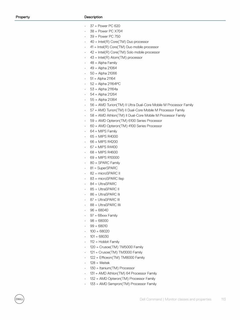
Property Description
• 37 = Power PC 620
• 38 = Power PC X704
• 39 = Power PC 750
• 40 = Intel(R) Core(TM) Duo processor
• 41 = Intel(R) Core(TM) Duo mobile processor
• 42 = Intel(R) Core(TM) Solo mobile processor
• 43 = Intel(R) Atom(TM) processor
• 48 = Alpha Family
• 49 = Alpha 21064
• 50 = Alpha 21066
• 51 = Alpha 21164
• 52 = Alpha 21164PC
• 53 = Alpha 21164a
• 54 = Alpha 21264
• 55 = Alpha 21364
• 56 = AMD Turion(TM) II Ultra Dual-Core Mobile M Processor Family
• 57 = AMD Turion(TM) II Dual-Core Mobile M Processor Family
• 58 = AMD Athlon(TM) II Dual-Core Mobile M Processor Family
• 59 = AMD Opteron(TM) 6100 Series Processor
• 60 = AMD Opteron(TM) 4100 Series Processor
• 64 = MIPS Family
• 65 = MIPS R4000
• 66 = MIPS R4200
• 67 = MIPS R4400
• 68 = MIPS R4600
• 69 = MIPS R10000
• 80 = SPARC Family
• 81 = SuperSPARC
• 82 = microSPARC II
• 83 = microSPARC IIep
• 84 = UltraSPARC
• 85 = UltraSPARC II
• 86 = UltraSPARC IIi
• 87 = UltraSPARC III
• 88 = UltraSPARC IIIi
• 96 = 68040
• 97 = 68xxx Family
• 98 = 68000
• 99 = 68010
• 100 = 68020
• 101 = 68030
• 112 = Hobbit Family
• 120 = Crusoe(TM) TM5000 Family
• 121 = Crusoe(TM) TM3000 Family
• 122 = Efficeon(TM) TM8000 Family
• 128 = Weitek
• 130 = Itanium(TM) Processor
• 131 = AMD Athlon(TM) 64 Processor Family
• 132 = AMD Opteron(TM) Processor Family
• 133 = AMD Sempron(TM) Processor Family
Dell Command | Monitor classes and properties 113
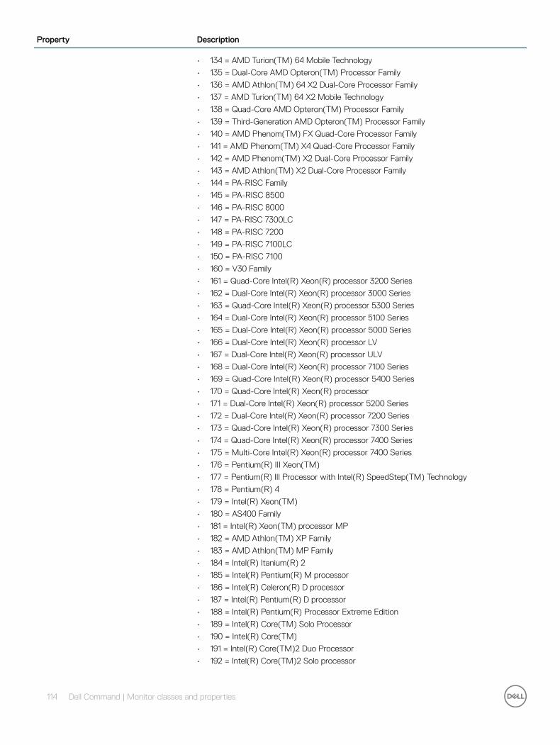
Property Description
• 134 = AMD Turion(TM) 64 Mobile Technology
• 135 = Dual-Core AMD Opteron(TM) Processor Family
• 136 = AMD Athlon(TM) 64 X2 Dual-Core Processor Family
• 137 = AMD Turion(TM) 64 X2 Mobile Technology
• 138 = Quad-Core AMD Opteron(TM) Processor Family
• 139 = Third-Generation AMD Opteron(TM) Processor Family
• 140 = AMD Phenom(TM) FX Quad-Core Processor Family
• 141 = AMD Phenom(TM) X4 Quad-Core Processor Family
• 142 = AMD Phenom(TM) X2 Dual-Core Processor Family
• 143 = AMD Athlon(TM) X2 Dual-Core Processor Family
• 144 = PA-RISC Family
• 145 = PA-RISC 8500
• 146 = PA-RISC 8000
• 147 = PA-RISC 7300LC
• 148 = PA-RISC 7200
• 149 = PA-RISC 7100LC
• 150 = PA-RISC 7100
• 160 = V30 Family
• 161 = Quad-Core Intel(R) Xeon(R) processor 3200 Series
• 162 = Dual-Core Intel(R) Xeon(R) processor 3000 Series
• 163 = Quad-Core Intel(R) Xeon(R) processor 5300 Series
• 164 = Dual-Core Intel(R) Xeon(R) processor 5100 Series
• 165 = Dual-Core Intel(R) Xeon(R) processor 5000 Series
• 166 = Dual-Core Intel(R) Xeon(R) processor LV
• 167 = Dual-Core Intel(R) Xeon(R) processor ULV
• 168 = Dual-Core Intel(R) Xeon(R) processor 7100 Series
• 169 = Quad-Core Intel(R) Xeon(R) processor 5400 Series
• 170 = Quad-Core Intel(R) Xeon(R) processor
• 171 = Dual-Core Intel(R) Xeon(R) processor 5200 Series
• 172 = Dual-Core Intel(R) Xeon(R) processor 7200 Series
• 173 = Quad-Core Intel(R) Xeon(R) processor 7300 Series
• 174 = Quad-Core Intel(R) Xeon(R) processor 7400 Series
• 175 = Multi-Core Intel(R) Xeon(R) processor 7400 Series
• 176 = Pentium(R) III Xeon(TM)
• 177 = Pentium(R) III Processor with Intel(R) SpeedStep(TM) Technology
• 178 = Pentium(R) 4
• 179 = Intel(R) Xeon(TM)
• 180 = AS400 Family
• 181 = Intel(R) Xeon(TM) processor MP
• 182 = AMD Athlon(TM) XP Family
• 183 = AMD Athlon(TM) MP Family
• 184 = Intel(R) Itanium(R) 2
• 185 = Intel(R) Pentium(R) M processor
• 186 = Intel(R) Celeron(R) D processor
• 187 = Intel(R) Pentium(R) D processor
• 188 = Intel(R) Pentium(R) Processor Extreme Edition
• 189 = Intel(R) Core(TM) Solo Processor
• 190 = Intel(R) Core(TM)
• 191 = Intel(R) Core(TM)2 Duo Processor
• 192 = Intel(R) Core(TM)2 Solo processor
114 Dell Command | Monitor classes and properties
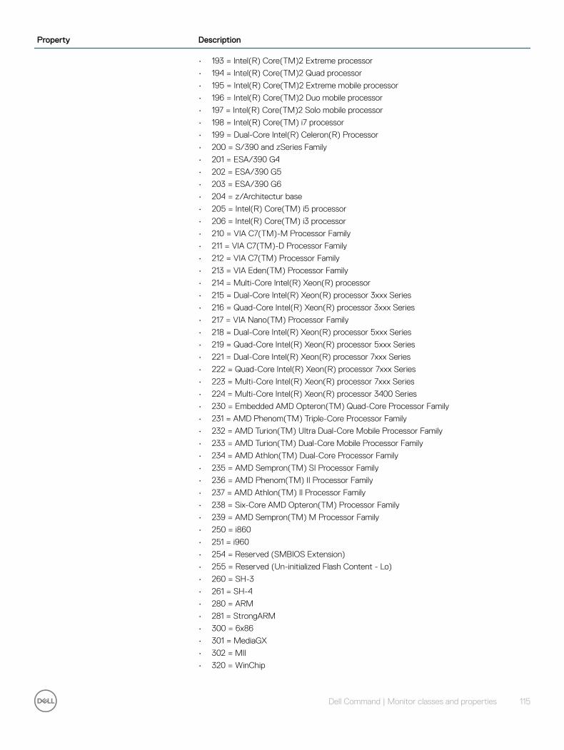
Property Description
• 193 = Intel(R) Core(TM)2 Extreme processor
• 194 = Intel(R) Core(TM)2 Quad processor
• 195 = Intel(R) Core(TM)2 Extreme mobile processor
• 196 = Intel(R) Core(TM)2 Duo mobile processor
• 197 = Intel(R) Core(TM)2 Solo mobile processor
• 198 = Intel(R) Core(TM) i7 processor
• 199 = Dual-Core Intel(R) Celeron(R) Processor
• 200 = S/390 and zSeries Family
• 201 = ESA/390 G4
• 202 = ESA/390 G5
• 203 = ESA/390 G6
• 204 = z/Architectur base
• 205 = Intel(R) Core(TM) i5 processor
• 206 = Intel(R) Core(TM) i3 processor
• 210 = VIA C7(TM)-M Processor Family
• 211 = VIA C7(TM)-D Processor Family
• 212 = VIA C7(TM) Processor Family
• 213 = VIA Eden(TM) Processor Family
• 214 = Multi-Core Intel(R) Xeon(R) processor
• 215 = Dual-Core Intel(R) Xeon(R) processor 3xxx Series
• 216 = Quad-Core Intel(R) Xeon(R) processor 3xxx Series
• 217 = VIA Nano(TM) Processor Family
• 218 = Dual-Core Intel(R) Xeon(R) processor 5xxx Series
• 219 = Quad-Core Intel(R) Xeon(R) processor 5xxx Series
• 221 = Dual-Core Intel(R) Xeon(R) processor 7xxx Series
• 222 = Quad-Core Intel(R) Xeon(R) processor 7xxx Series
• 223 = Multi-Core Intel(R) Xeon(R) processor 7xxx Series
• 224 = Multi-Core Intel(R) Xeon(R) processor 3400 Series
• 230 = Embedded AMD Opteron(TM) Quad-Core Processor Family
• 231 = AMD Phenom(TM) Triple-Core Processor Family
• 232 = AMD Turion(TM) Ultra Dual-Core Mobile Processor Family
• 233 = AMD Turion(TM) Dual-Core Mobile Processor Family
• 234 = AMD Athlon(TM) Dual-Core Processor Family
• 235 = AMD Sempron(TM) SI Processor Family
• 236 = AMD Phenom(TM) II Processor Family
• 237 = AMD Athlon(TM) II Processor Family
• 238 = Six-Core AMD Opteron(TM) Processor Family
• 239 = AMD Sempron(TM) M Processor Family
• 250 = i860
• 251 = i960
• 254 = Reserved (SMBIOS Extension)
• 255 = Reserved (Un-initialized Flash Content - Lo)
• 260 = SH-3
• 261 = SH-4
• 280 = ARM
• 281 = StrongARM
• 300 = 6x86
• 301 = MediaGX
• 302 = MII
• 320 = WinChip
Dell Command | Monitor classes and properties 115

Property Description
• 350 = DSP
• 500 = Video Processor
• 65534 = Reserved (For Future Special Purpose Assignment)
• 65535 = Reserved (Un-initialized Flash Content - Hi)
For example, values include Pentium(R) processor with MMX(TM) technology (value = 14) and 68040 (value = 96).
HealthState Indicates the current health of the element. This attribute expresses the health of this element but not necessarily that of its subcomponents.
DMTF has reserved the unused portion of the continuum for additional HealthStates in the future.
Possible values are:
• 0 = Unknown — The implementation cannot report on HealthState at this time.
• 5 = OK — The element is fully functional and is operating within normal operational parameters and without error.
• 10 = Degraded/Warning — The element is in working order and all functionality is provided. However, the element is not working to the best of its abilities. For example, the element may not be operating at optimal performance or it may be reporting recoverable errors.
• 15 = Minor failure — All functionality is available but some may be degraded.
• 20 = Major failure — The element is failing. It is possible that some or all of the functionality of this component is degraded or not working.
• 25 = Critical failure — The element is non-functional and recovery may not be possible.
• 30 = Non-recoverable error — The element has completely failed, and recovery is not possible. All functionality provided by this element has been lost.
• .. = DMTF Reserved
MaxClockSpeed The maximum speed (in MHz) of this Processor.
NumberOfEnabledCores Number of processor cores enabled for processor.
OperationalStatus Indicates the current statuses of the element. Various operational statuses are defined. Many of the enumeration's values are self-explanatory. However, a few are not and are described here in more detail.
Possible values are:
• 0 = Unknown
• 1 = Other
• 2 = OK
• 3 = Degraded
• 4 = Stressed — Indicates that the element is functioning, but needs attention. Examples of Stressed states are overload, overheated, and so on.
• 5 = Predictive Failure — Indicates that an element is functioning nominally but predicting a failure in the near future.
• 6 = Error
• 7 = Non-Recoverable Error
• 8 = Starting
• 9 = Stopping
• 10 = Stopped — Implies a clean and orderly stop.
• 11 = In Service — Describes an element being configured, maintained, cleaned, or otherwise administered.
• 12 = No Contact — Indicates that the monitoring system has knowledge of this element, but has never been able to establish communications with it.
116 Dell Command | Monitor classes and properties

Property Description
• 13 = Lost Communication — Indicates that the ManagedSystem Element is known to exist and has been contacted successfully in the past, but is currently unreachable.
• 14 = Aborted — Implies an abrupt stop where the state and configuration of the element may need to be updated.
• 15 = Dormant — Indicates that the element is inactive or quiesced.
• 16 = Supporting Entity in Error — Indicates that this element may be OK but that another element, on which it is dependent, is in error. An example is a network service or endpoint that cannot function due to lower-layer networking problems.
• 17 = Completed — Indicates that the element has completed its operation. This value should be combined with either OK, Error, or Degraded so that a client can tell if the complete operation Completed with OK (passed), Completed with Error (failed), or Completed with Degraded (the operation finished, but it did not complete OK or did not report an error).
• 18 = Power Mode — Indicates that the element has additional power model information contained in the Associated PowerManagementService association.
• .. = DMTF Reserved
• 0x8000.. = Vendor Reserved
OperationalStatus replaces the Status property on ManagedSystemElement to provide a consistent approach to enumerations, to address implementation needs for an array property, and to provide a migration path from today's environment to the future. This change was not made earlier because it required the deprecated qualifier. Due to the widespread use of the existing Status property in management applications, it is strongly recommended that providers or instrumentation provide both the Status and OperationalStatus properties. Further, the first value of OperationalStatus should contain the primary status for the element. When instrumented, Status (because it is single-valued) should also provide the primary status of the element.
PrimaryStatus Provides a high level status value, intended to align with Red-Yellow-Green type representation of status. It should be used in conjunction with DetailedStatus to provide high level and detailed health status of the ManagedElement and its subcomponents.
Possible values are:
• 0 = Unknown — Indicates the implementation is in general capable of returning this property, but is unable to do so at this time.
• 1 = OK — Indicates the ManagedElement is functioning normally.
• 2 = Degraded — Indicates the ManagedElement is functioning below normal.
• 3 = Error - Indicates the ManagedElement is in an Error condition.
• .. = DMTF Reserved
• 0x8000.. = Vendor Reserved
RequestedState An integer enumeration that indicates the last requested or desired state for the element, irrespective of the mechanism through which it was requested. The actual state of the element is represented by EnabledState. This property is provided to compare the last requested and current enabled or disabled states.
Possible values are:
• 0 = Unknown
• 2 = Enabled
• 3 = Disabled
• 4 = Shut Down
• 5 = No Change
• 6 = Offline
• 7 = Test
• 8 = Deferred
• 9 = Quiesce
• 10 = Reboot
• 11 = Reset
Dell Command | Monitor classes and properties 117

Property Description
• 12 = Not Applicable
• .. = DMTF Reserved
• 32768..65535 = Vendor Reserved
NOTE: When EnabledState is set to 5 (Not Applicable), then this property has no meaning. Refer to the EnabledState property description for explanations of the values in the RequestedState enumeration. Unknown (0) indicates the last requested state for the element is unknown.
NOTE: The value No Change (5) has been deprecated instead of indicating the last requested state is Unknown (0). If the last requested or desired state is unknown, RequestedState should have the value Unknown (0), but may have the value No Change (5). Offline (6) indicates that the element has been requested to transition to the Enabled but Offline EnabledState. There are two new values in RequestedState that build on the statuses of EnabledState. These are Reboot (10) and Reset (11). Reboot refers to doing a Shut Down and then moving to an Enabled state. Reset indicates that the element is first Disabled and then Enabled.
Shut Down requests an orderly transition to the Disabled state, and may involve removing power, to completely erase any existing state. The Disabled state requests an immediate disabling of the element, such that it will not execute or accept any commands or processing requests.
This property is set as the result of a method invocation (such as Start or StopService on CIM_Service), or can be overridden and defined as WRITEable in a subclass. The method approach is considered superior to a WRITEable property, because it allows an explicit invocation of the operation and the return of a result code.
If knowledge of the last RequestedState is not supported for the EnabledLogicalElement, the property is NULL or has the value 12 Not Applicable.
Stepping Stepping is a free-form string that indicates the revision level of the Processor within the Processor.Family.
SystemCreationClassName The CreationClassName of the scoping system.
SystemName The System Name of the scoping system.
TransitioningToState Indicates the target state to which the instance is transitioning.
Possible values are:
• 0 = Unknown
• 2 = Enabled
• 3 = Disabled
• 4 = Shut Down
• 5 = No Change — Indicates that no transition is in progress.
• 6 = Offline
• 7 = Test
• 8 = Defer
• 9 = Quiesce
• 10 = Reboot
• 11 = Reset
• 12 = Not Applicable — Indicates the implementation does not support representing ongoing transitions.
A value other than 5 or 12 identifies the state to which the element is in the process of transitioning.
118 Dell Command | Monitor classes and properties
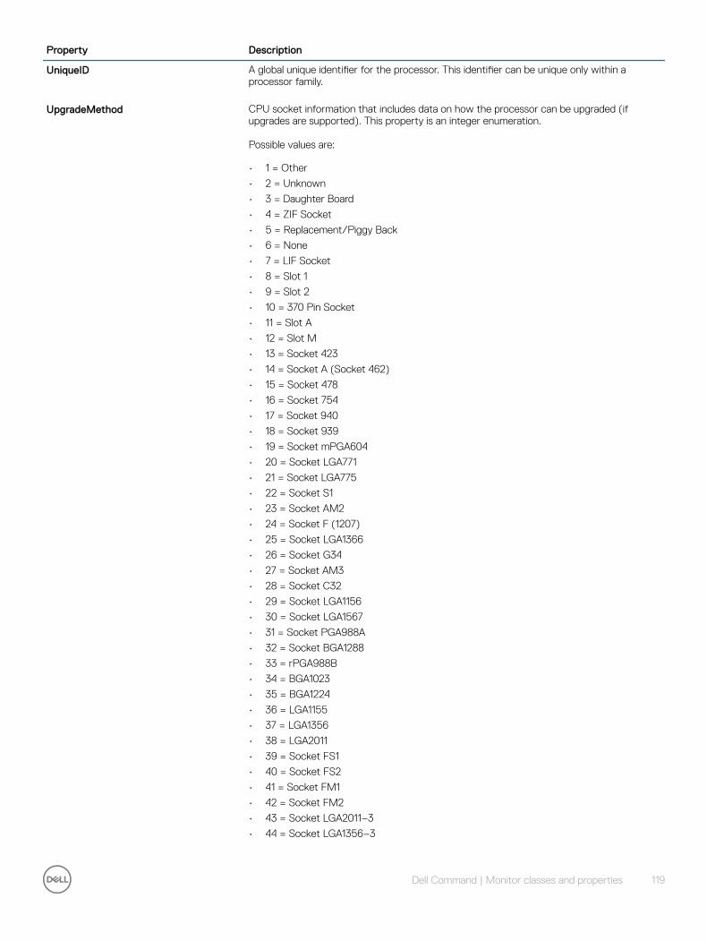
Property Description
UniqueID A global unique identifier for the processor. This identifier can be unique only within a processor family.
UpgradeMethod CPU socket information that includes data on how the processor can be upgraded (if upgrades are supported). This property is an integer enumeration.
Possible values are:
• 1 = Other
• 2 = Unknown
• 3 = Daughter Board
• 4 = ZIF Socket
• 5 = Replacement/Piggy Back
• 6 = None
• 7 = LIF Socket
• 8 = Slot 1
• 9 = Slot 2
• 10 = 370 Pin Socket
• 11 = Slot A
• 12 = Slot M
• 13 = Socket 423
• 14 = Socket A (Socket 462)
• 15 = Socket 478
• 16 = Socket 754
• 17 = Socket 940
• 18 = Socket 939
• 19 = Socket mPGA604
• 20 = Socket LGA771
• 21 = Socket LGA775
• 22 = Socket S1
• 23 = Socket AM2
• 24 = Socket F (1207)
• 25 = Socket LGA1366
• 26 = Socket G34
• 27 = Socket AM3
• 28 = Socket C32
• 29 = Socket LGA1156
• 30 = Socket LGA1567
• 31 = Socket PGA988A
• 32 = Socket BGA1288
• 33 = rPGA988B
• 34 = BGA1023
• 35 = BGA1224
• 36 = LGA1155
• 37 = LGA1356
• 38 = LGA2011
• 39 = Socket FS1
• 40 = Socket FS2
• 41 = Socket FM1
• 42 = Socket FM2
• 43 = Socket LGA2011–3
• 44 = Socket LGA1356–3
Dell Command | Monitor classes and properties 119

Property Description
• 45 = Socket LGA1150
• 46 = Socket BGA1168
DCIM_NumericSensorProperty Description Supported
Operating System(s)
BaseUnits The base unit of the values returned by this Sensor. All the values returned by this Sensor are represented in the units obtained by (BaseUnits * 10 raised to the power of the UnitModifier). For example, if BaseUnits is Volts and the UnitModifier is -6, then the units of the values returned are MicroVolts. However, if the RateUnits property is set to a value other than None, then the units are further qualified as rate units. In the above example, if RateUnits is set to Per Second, then the values returned by the Sensor are in MicroVolts/Second. The units apply to all numeric properties of the Sensor, unless explicitly overridden by the Units qualifier.
Possible values are:
• 0 = Unknown
• 1 = Other
• 2 = Degrees C
• 3 = Degrees F
• 4 = Degrees K
• 5 = Volts
• 6 = Amps
• 7 = Watts
• 8 = Joules
• 9 = Coulombs
• 10 = VA
• 11 = Nits
• 12 = Lumens
• 13 = Lux
• 14 = Candelas
• 15 = kPa
• 16 = PSI
• 17 = Newtons
• 18 = CFM
• 19 = RPM
• 20 = Hertz
• 21 = Seconds
• 22 = Minutes
• 23 = Hours
• 24 = Days
• 25 = Weeks
• 26 = Mils
• 27 = Inches
• 28 = Feet
• 29 = Cubic Inches
• 30 = Cubic Feet
• 31 = Meters
• 32 = Cubic Centimeters
Microsoft Windows, Linux
120 Dell Command | Monitor classes and properties
Property Description Supported Operating System(s)
• 33 = Cubic Meters
• 34 = Liters
• 35 = Fluid Ounces
• 36 = Radians
• 37 = Steradians
• 38 = Revolutions
• 39 = Cycles
• 40 = Gravities
• 41 = Ounces
• 42 = Pounds
• 43 = Foot-Pounds
• 44 = Ounce-Inches
• 45 = Gauss
• 46 = Gilberts
• 47 = Henries
• 48 = Farads
• 49 = Ohms
• 50 = Siemens
• 51 = Moles
• 52 = Becquerels
• 53 = PPM (parts/million)
• 54 = Decibels
• 55 = DbA
• 56 = DbC
• 57 = Grays
• 58 = Sieverts
• 59 = Color Temperature Degrees K
• 60 = Bits
• 61 = Bytes
• 62 = Words (data)
• 63 = DoubleWords
• 64 = QuadWords
• 65 = Percentage
• 66 = Pascals
CreationClassName Indicates the name of the class or the subclass used in the creation of an instance. When used with the other key properties of this class, this property allows all instances of this class and its subclasses to be uniquely identified.
Microsoft Windows, Linux
CurrentReading The current value indicated by the Sensor. Microsoft Windows, Linux
CurrentState The current state indicated by the Sensor. This is always one of the PossibleStates. Microsoft Windows, Linux
DeviceID An address or other identifying information used to uniquely name the LogicalDevice. Microsoft Windows, Linux
ElementName A user-friendly name for the object. This property allows each instance to define a user-friendly name in addition to its key properties, identity data, and description information.
Microsoft Windows, Linux
Dell Command | Monitor classes and properties 121
Property Description Supported Operating System(s)
NOTE: The Name property of ManagedSystemElement is also defined as a user-friendly name. But, it is often subclassed to be a Key. It is not reasonable that the same property can convey both identity and a user-friendly name, without inconsistencies. Where Name exists and is not a Key (such as for instances of LogicalDevice), the same information can be present in both the Name and ElementName properties. We have introduced new elements for Temperature sensor, Fan Speed Sensor, Current Supply and Voltage Numeric Sensor.
EnabledDefault An enumerated value indicating an administrator's default or startup configuration for the Enabled State of an element.
Possible values are:
• 2 = Enabled
• 3 = Disabled
• 5 = Not Applicable
• 6 = Enabled but Offline
• 7 = No Default
• 9 = Quiesce
• .. = DMTF Reserved
• 32768..65535 = Vendor Reserved
By default, the element is Enabled (value = 2).
Microsoft Windows, Linux
EnabledState An integer enumeration that indicates the enabled and disabled states of an element. It can also indicate the transitions between these requested states.
Possible values are:
• 0 = Unknown
• 1 = Other
• 2 = Enabled — Indicates that the element is or could be executing commands, will process any queued commands, and queues new requests.
• 3 = Disabled — Indicates that the element will not execute commands and will drop any new requests.
• 4 = Shutting Down — Indicates that the element is in the process of going to a Disabled state.
• 5 = Not Applicable — Indicates the element does not support being enabled or disabled.
• 6 = Enabled but Offline — Indicates that the element may be completing commands, and will drop any new requests.
• 7 = In Test — Indicates that the element is in a test state.
• 8 = Deferred — Indicates that the element may be completing commands, but will queue any new requests.
• 9 = Quiesce — Indicates that the element is enabled but in a restricted mode.
• 10 = Starting — Indicates that the element is in the process of going to an Enabled state. New requests are queued.
• 11..32767 = DMTF Reserved
• 32768..65535 = Vendor Reserved
For example, shutting down (value = 4) and starting (value = 10) are transient states between enabled and disabled.
Microsoft Windows, Linux
HealthState Indicates the current health of the element. This attribute expresses the health of this element but not necessarily that of its subcomponents.
Microsoft Windows, Linux
122 Dell Command | Monitor classes and properties
Property Description Supported Operating System(s)
Possible values are:
• 0 = Unknown — The implementation cannot report on HealthState at this time.
• 5 = OK — The element is fully functional and is operating within normal operational parameters and without error.
• 10 = Degraded/Warning — The element is in working order and all functionality is provided. However, the element is not working to the best of its abilities. For example, the element may not be operating at optimal performance or it may be reporting recoverable errors.
• 15 = Minor failure — All functionality is available but some may be degraded.
• 20 = Major failure — The element is failing. It is possible that some or all of the functionality of this component is degraded or not working.
• 25 = Critical failure — The element is non-functional and recovery may not be possible.
• 30 = Non-recoverable error — The element has completely failed, and recovery is not possible. All functionality provided by this element has been lost.
• .. = DMTF Reserved
DMTF has reserved the unused portion of the continuum for additional HealthStates in the future.
LowerThresholdCritical The Sensor's threshold values specify the ranges (min and max values) for determining whether the Sensor is operating under Normal, NonCritical or Critical conditions. The CurrentState is Critical once the CurrentReading is below LowerThresholdCritical.
Microsoft Windows, Linux
LowerThresholdNonCritical
The Sensor's threshold values specify the ranges (min and max values) for determining whether the Sensor is operating under Normal, NonCritical, Critical conditions. If Current Reading is between LowerThresholdNonCritical and Upper ThresholdNonCritical, then the Sensor is reporting a normal value. If CurrentReading is between LowerThresholdNonCritical and LowerThresholdCritical, then the CurrentState is NonCritical.
Example for Set command: wmic /namespace:\\root\dcim\sysman path dcim_numericsensor Where ElementName like '%Temperature Sensor:%' set LowerThresholdNonCritical = 30. This sets the all temperature probes (lower threshold non critical) in the system to 30 degree Celsius.
Microsoft Windows, Linux
NormalMax NormalMax provides guidance for the user as to the normal maximum range for the NumericSensor.
Linux
NormalMin NormalMin provides guidance for the user as to the normal minimum range for the NumericSensor.
Linux
OperationalStatus Indicates the current statuses of the element. Various operational statuses are defined. Many of the enumeration's values are self-explanatory.
Possible values are:
• 0 = Unknown• 1 = Other• 2 = OK• 3 = Degraded• 4 = Stressed — Indicates that the element is functioning, but needs attention.
Examples of Stressed states are overload, overheated, and so on.• 5 = Predictive Failure — Indicates that an element is functioning nominally but
predicting a failure in the near future.• 6 = Error• 7 = Non-Recoverable Error• 8 = Starting• 9 = Stopping
Microsoft Windows, Linux
Dell Command | Monitor classes and properties 123

Property Description Supported Operating System(s)
• 10 = Stopped — Implies a clean and orderly stop
• 11 = In Service — Describes an element being configured, maintained, cleaned, or otherwise administered.
• 12 = No Contact — Indicates that the monitoring system has knowledge of this element, but has never been able to establish communications with it.
• 13 = Lost Communication — Indicates that the ManagedSystem Element is known to exist and has been contacted successfully in the past, but is currently unreachable.
• 14 = Aborted — Implies an abrupt stop where the state and configuration of the element may need to be updated.
• 15 = Dormant - Indicates that the element is inactive or quiesced.
• 16 = Supporting Entity in Error — Indicates that this element may be OK but that another element, on which it is dependent, is in error. An example is a network service or endpoint that cannot function due to lower-layer networking problems.
• 17 = Completed — Indicates that the element has completed its operation. This value should be combined with either OK, Error, or Degraded so that a client can tell if the complete operation Completed with OK (passed), Completed with Error (failed), or Completed with Degraded (the operation finished, but it did not complete OK or did not report an error).
• 18 = Power Mode — Indicates that the element has additional power model information contained in the Associated PowerManagementService association.
• .. = DMTF Reserved
• 0x8000.. = Vendor Reserved
OperationalStatus replaces the Status property on ManagedSystemElement to provide a consistent approach to enumerations, to address implementation needs for an array property, and to provide a migration path from today's environment to the future. This change was not made earlier because it required the deprecated qualifier. Due to the widespread use of the existing Status property in management applications, it is strongly recommended that providers or instrumentation provide both the Status and OperationalStatus properties. Further, the first value of OperationalStatus should contain the primary status for the element. When instrumented, Status (because it is single-valued) should also provide the primary status of the element.
PossibleStates Enumerates the string outputs of the Sensor.
Example 1 - A Switch Sensor may output the states On, or Off. Another implementation of the Switch may output the states Open, and Close.
Example 2 - Is a NumericSensor supporting thresholds. This Sensor can report the states like Normal, Upper Non-Critical, Lower Non-Critical, and so on. A NumericSensor that does not publish readings and thresholds, but stores this data internally, can still report its states.
Microsoft Windows, Linux
RateUnits Specifies if the units returned by this Sensor are rate units. All the values returned by this Sensor are represented in the units obtained by (BaseUnits * 10 raised to the power of the UnitModifier). This is true unless this property (RateUnits) has a value different than None. For example, if BaseUnits is Volts and the UnitModifier is -6, then the units of the values returned are MicroVolts. But, if the RateUnits property is set to a value other than None, then the units are further qualified as rate units. In the above example, if RateUnits is set to Per Second, then the values returned by the Sensor are in MicroVolts/Second. The units apply to all numeric properties of the Sensor, unless explicitly overridden by the Units qualifier. Any implementation of CurrentReading should be qualified with either a Counter or a Gauge qualifier, depending on the characteristics of the sensor being modeled.
Possible values are:
• 0 = None
• 1 = Per MicroSecond
• 2 = Per MilliSecond
• 3 = Per Second
Microsoft Windows, Linux
124 Dell Command | Monitor classes and properties

Property Description Supported Operating System(s)
• 4 = Per Minute
• 5 = Per Hour
• 6 = Per Day
• 7 = Per Week
• 8 = Per Month
• 9 = Per Year
RequestedState An integer enumeration that indicates the last requested or desired state for the element, irrespective of the mechanism through which it was requested. The actual state of the element is represented by EnabledState. This property is provided to compare the last requested and current enabled or disabled states. Note that when EnabledState is set to 5 (Not Applicable), then this property has no meaning. Refer to the EnabledState property description for explanations of the values in the RequestedState enumeration.
NOTE: The value No Change (5) has been deprecated instead of indicating the last requested state is Unknown (0). If the last requested or desired state is unknown, RequestedState should have the value Unknown (0), but may have the value No Change (5). Offline (6) indicates that the element has been requested to transition to the Enabled but Offline EnabledState.
There are two new values in RequestedState that build on the statuses of EnabledState. These are Reboot (10) and Reset (11).
Shut Down requests an orderly transition to the Disabled state, and may involve removing power, to completely erase any existing state. The Disabled state requests an immediate disabling of the element, such that it will not execute or accept any commands or processing requests.
This property is set as the result of a method invocation (such as Start or StopService on CIM_Service), or can be overridden and defined as WRITEable in a subclass. The method approach is considered superior to a WRITEable property, because it allows an explicit invocation of the operation and the return of a result code.
If knowledge of the last RequestedState is not supported for the EnabledLogicalElement, the property is NULL or has the value 12 Not Applicable.
Possible values are:
• 0 = Unknown — Indicates the last requested state for the element is unknown.
• 2 = Enabled
• 3 = Disabled
• 4 = Shut Down
• 5 = No Change
• 6 = Offline
• 7 = Test
• 8 = Deferred
• 9 = Quiesce
• 10 = Reboot — Refers to doing a Shut Down and then moving to an Enabled state.
• 11 = Reset — Indicates that the element is first Disabled and then Enabled.
• 12 = Not Applicable
• .. = DMTF Reserved
• 32768..65535 = Vendor Reserved
Microsoft Windows, Linux
SensorType The Type of the Sensor, e.g. Voltage or Temperature Sensor. If the type is set to Other, then the OtherSensorType Description can be used to further identify the type, or if the Sensor has numeric readings, then the type of the Sensor can be implicitly determined by
Microsoft Windows, Linux
Dell Command | Monitor classes and properties 125

Property Description Supported Operating System(s)
the Units. A description of the different Sensor types is as follows: A Temperature Sensor measures the environmental temperature. Voltage and Current Sensors measure electrical voltage and current readings. A Tachometer measures speed/revolutions of a Device. For example, a Fan Device can have an associated Tachometer which measures its speed. A Counter is a general purpose Sensor that measures some numerical property of a Device. A Counter value can be cleared, but it never decreases. A Switch Sensor has states like Open/Close, On/Off, or Up/Down. A Lock has states of Locked/Unlocked. Humidity, Smoke Detection and Air Flow Sensors measure the equivalent environmental characteristics. A Presence Sensor detects the presence of a PhysicalElement. A Power Consumption Sensor measures the instantaneous power consumed by a managed element. A Power Production Sensor measures the instantaneous power produced by a managed element such as a power supply or a voltage regulator. A pressure sensor is used to report pressure. Intrusion sensor reports an intrusion of an enclosure regardless whether it was authorized or not.
Possible values are:
• 0 = Unknown
• 1 = Other
• 2 = Temperature
• 3 = Voltage
• 4 = Current
• 5 = Tachometer
• 6 = Counter
• 7 = Switch
• 8 = Lock
• 9 = Humidity
• 10 = Smoke Detection
• 11 = Presence
• 12 = Air Flow
• 13 = Power Consumption
• 14 = Power Production
• 15 = Pressure
• 16 = Intrusion
• .. = DMTF Reserved
• 32768..65535 = Vendor Reserved
SystemCreationClassName
The CreationClassName of the scoping system. Microsoft Windows, Linux
SystemName The System Name of the scoping system. Microsoft Windows, Linux
TransitioningToState Indicates the target state to which the instance is transitioning.
Possible values are:
• 0 = Unknown
• 2 = Enabled
• 3 = Disabled
• 4 = Shut Down
• 5 = No Change — Indicates that no transition is in progress.
• 6 = Offline
• 7 = Test
• 8 = Defer
• 9 = Quiesce
Microsoft Windows, Linux
126 Dell Command | Monitor classes and properties
Property Description Supported Operating System(s)
• 10 = Reboot
• 11 = Reset
• 12 = Not Applicable — Indicates the implementation does not support representing ongoing transitions.
A value other than 5 or 12 identifies the state to which the element is in the process of transitioning.
UnitModifier The unit multiplier for the values returned by this Sensor. All the values returned by this Sensor are represented in the units obtained by (BaseUnits * 10 raised to the power of the UnitModifier).
For example, if BaseUnits is Volts and the Unit Modifier is -6, then the units of the values returned are MicroVolts. However, if the RateUnits property is set to a value other than None, then the units are further qualified as rate units.
In the above example, if RateUnits is set to Per Second, then the values returned by the Sensor are in MicroVolts/Second. The units apply to all numeric properties of the Sensor, unless explicitly overridden by the Units qualifier.
Microsoft Windows, Linux
UpperThresholdCritical The Sensor's threshold values specify the ranges (min and max values) for determining whether the Sensor is operating under Normal, NonCritical, Critical conditions. If the CurrentReading is above UpperThresholdCritical, then the Current State is critical.
Microsoft Windows, Linux
UpperThresholdNonCritical
The Sensor's threshold values specify the ranges (min and max values) for determining whether the Sensor is operating under Normal, NonCritical or Critical conditions. If the CurrentReading is between LowerThresholdNonCritical and UpperThresholdNonCritical, then the Sensor is reporting a normal value. If the CurrentReading is between UpperThreshold NonCritical and UpperThresholdCritical, then the CurrentState is NonCritical.
Example for Set command: wmic /namespace:\\root\dcim\sysman path dcim_numericsensor Where ElementName like '%Temperature Sensor:%’ set UpperThresholdNonCritical = 70
Microsoft Windows, Linux
ValueFormulation Indicates the method used by the sensor to produce its reading.
Possible values are:
• 0 = Unknown
• 2 = Measured - Indicates the value is measured directly by the sensor.
• 3 = Derived - Indicates the value is derived from other measured values that are not reported discretely by this sensor.
• .. = DMTF Reserved
• 32768..65535 = Vendor Reserved
Microsoft Windows, Linux
SupportedThresholds SupportedThresholds property is an array that contains the list of the implemented thresholds: LowerThresholdNonCritical, UpperThresholdNonCritical, LowerThresholdCritical, UpperThresholdCritical. When the implementation does not support any of these threshold properties, the CIM_NumericSensor.SupportedThresholds property shall be an empty array.
Microsoft Windows, Linux
SettableThresholds SettableThresholds property is an array that contains the list of the settable implemented thresholds: LowerThresholdNonCritical, UpperThresholdNonCritical. The CIM_NumericSensor.SettableThresholds array shall contain the subset of values in the CIM_NumericSensor.SupportedThresholds array. When the implementation does not support any of the settable threshold properties, the CIM_NumericSensor.SettableThresholds property shall be an empty array.
Microsoft Windows, Linux
Dell Command | Monitor classes and properties 127

Property Description Supported Operating System(s)
Caption A short textual description of an object. Microsoft Windows, Linux
Description A short textual description of an object. Microsoft Windows, Linux
DCIM_SensorProperty Description
Caption The Caption property is a short textual description (one- line string) of the object.
CreationClassName Indicates the name of the class or the subclass used in the creation of an instance. When used with the other key properties of this class, this property allows all instances of this class and its subclasses to be uniquely identified.
CurrentState The current state indicated by the Sensor. This is always one of the PossibleStates.
DeviceID An address or other identifying information used to uniquely name the LogicalDevice.
ElementName A user-friendly name for the object. This property allows each instance to define a user-friendly name in addition to its key properties, identity data, and description information.
NOTE: The Name property of ManagedSystemElement is also defined as a user-friendly name. But, it is often subclassed to be a Key. It is not reasonable that the same property can convey both identity and a user-friendly name, without inconsistencies. Where Name exists and is not a Key (such as for instances of LogicalDevice), the same information can be present in both the Name and ElementName properties.
EnabledDefault An enumerated value indicating an administrator's default or startup configuration for the Enabled State of an element.
Possible values are:
• 2 = Enabled
• 3 = Disabled
• 5 = Not Applicable
• 6 = Enabled but Offline
• 7 = No Default
• 9 = Quiesce
• .. = DMTF Reserved
• 32768..65535 = Vendor Reserved
By default, the element is Enabled (value = 2).
EnabledState An integer enumeration that indicates the enabled and disabled states of an element. It can also indicate the transitions between these requested states.
Possible values are:
• 0 = Unknown
• 1 = Other
• 2 = Enabled — Indicates that the element is or could be executing commands, will process any queued commands, and queues new requests.
• 3 = Disabled — Indicates that the element will not execute commands and will drop any new requests.
128 Dell Command | Monitor classes and properties

Property Description
• 4 = Shutting Down — Indicates that the element is in the process of going to a Disabled state.
• 5 = Not Applicable — Indicates the element does not support being enabled or disabled.
• 6 = Enabled but Offline — Indicates that the element may be completing commands, and will drop any new requests.
• 7 = In Test — Indicates that the element is in a test state.
• 8 = Deferred — Indicates that the element may be completing commands, but will queue any new requests.
• 9 = Quiesce — Indicates that the element is enabled but in a restricted mode.
• 10 = Starting — Indicates that the element is in the process of going to an Enabled state. New requests are queued.
• 11..32767 = DMTF Reserved
• 32768..65535 = Vendor Reserved
For example, shutting down (value = 4) and starting (value = 10) are transient states between enabled and disabled.
HealthState Indicates the current health of the element. This attribute expresses the health of this element but not necessarily that of its subcomponents.
DMTF has reserved the unused portion of the continuum for additional HealthStates in the future.
Possible values are:
• 0 = Unknown — The implementation cannot report on HealthState at this time.
• 5 = OK — The element is fully functional and is operating within normal operational parameters and without error.
• 10 = Degraded/Warning — The element is in working order and all functionality is provided. However, the element is not working to the best of its abilities. For example, the element may not be operating at optimal performance or it may be reporting recoverable errors.
• 15 = Minor failure — All functionality is available but some may be degraded.
• 20 = Major failure — The element is failing. It is possible that some or all of the functionality of this component is degraded or not working.
• 25 = Critical failure — The element is non-functional and recovery may not be possible.
• 30 = Non-recoverable error — The element has completely failed, and recovery is not possible. All functionality provided by this element has been lost.
• .. = DMTF Reserved
OperationalStatus Indicates the current statuses of the element. Various operational statuses are defined. Many of the enumeration's values are self-explanatory. However, a few are not and are described here in more detail.
Stressed, Predictive Failure, In Service, No Contact, Lost Communication, Stopped and Aborted are similar, although the former , while the latter Dormant, Supporting Entity in Error, Completed, Power Mode, OperationalStatus replaces the Status property on ManagedSystemElement to provide a consistent approach to enumerations, to address implementation needs for an array property, and to provide a migration path from today's environment to the future. This change was not made earlier because it required the deprecated qualifier. Due to the widespread use of the existing Status property in management applications, it is strongly recommended that providers or instrumentation provide both the Status and OperationalStatus properties. Further, the first value of OperationalStatus should contain the primary status for the element. When instrumented, Status (because it is single-valued) should also provide the primary status of the element.
Possible values are:
• 0 = Unknown
• 1 = Other
• 2 = OK
Dell Command | Monitor classes and properties 129

Property Description
• 3 = Degraded
• 4 = Stressed — Indicates that the element is functioning, but needs attention. Examples of Stressed states are overload, overheated, and so on.
• 5 = Predictive Failure — Indicates that an element is functioning nominally but predicting a failure in the near future.
• 6 = Error
• 7 = Non-Recoverable Error
• 8 = Starting
• 9 = Stopping
• 10 = Stopped — Implies a clean and orderly stop.
• 11 = In Service — Describes an element being configured, maintained, cleaned, or otherwise administered.
• 12 = No Contact — Indicates that the monitoring system has knowledge of this element, but has never been able to establish communications with it.
• 13 = Lost Communication — Indicates that the ManagedSystem Element is known to exist and has been contacted successfully in the past, but is currently unreachable.
• 14 = Aborted — Implies an abrupt stop where the state and configuration of the element may need to be updated.
• 15 = Dormant — Indicates that the element is inactive or quiesced.
• 16 = Supporting Entity in Error — Indicates that this element may be OK but that another element, on which it is dependent, is in error. An example is a network service or endpoint that cannot function due to lower-layer networking problems.
• 17 = Completed — Indicates that the element has completed its operation. This value should be combined with either OK, Error, or Degraded so that a client can tell if the complete operation Completed with OK (passed), Completed with Error (failed), or Completed with Degraded (the operation finished, but it did not complete OK or did not report an error).
• 18 = Power Mode — Indicates that the element has additional power model information contained in the Associated PowerManagementService association.
• .. = DMTF Reserved
• 0x8000.. = Vendor Reserved
PossibleStates Enumerates the string outputs of the Sensor. For example, a Switch Sensor may output the states On, or Off. Another implementation of the Switch may output the states Open, and Close. Another example is a NumericSensor supporting thresholds. This Sensor can report the states like Normal, Upper Fatal, Lower Non-Critical, and so on. A NumericSensor that does not publish readings and thresholds, but stores this data internally, can still report its states.
PrimaryStatus Provides a high level status value, intended to align with Red-Yellow-Green type representation of status. It should be used in conjunction with DetailedStatus to provide high level and detailed health status of the ManagedElement and its subcomponents.
Possible values are:
• 0 = Unknown — Indicates the implementation is in general capable of returning this property, but is unable to do so at this time.
• 1 = OK — Indicates the ManagedElement is functioning normally.
• 2 = Degraded — Indicates the ManagedElement is functioning below normal.
• 3 = Error — Indicates the ManagedElement is in an Error condition.
• .. = DMTF Reserved
• 0x8000.. = Vendor Reserved
RequestedState An integer enumeration that indicates the last requested or desired state for the element, irrespective of the mechanism through which it was requested. The actual state of the element is represented by EnabledState. This property is provided to compare the last requested and current enabled or disabled states. Note that when EnabledState is set to 5 (Not Applicable), then this property has no meaning. Refer to the EnabledState property
130 Dell Command | Monitor classes and properties
Property Description
description for explanations of the values in the RequestedState enumeration. Unknown (0) indicates the last requested state for the element is unknown.
NOTE: The value No Change (5) has been deprecated instead of indicating the last requested state is Unknown (0). If the last requested or desired state is unknown, RequestedState should have the value Unknown (0), but may have the value No Change (5). Offline (6) indicates that the element has been requested to transition to the Enabled but Offline EnabledState. There are two new values in RequestedState that build on the statuses of EnabledState. These are Reboot (10) and Reset (11). Reboot refers to doing a Shut Downand then moving to an Enabled state. Reset indicates that the element is first Disabled and then Enabled.
Shut Down requests an orderly transition to the Disabled state, and may involve removing power, to completely erase any existing state. The Disabled state requests an immediate disabling of the element, such that it will not execute or accept any commands or processing requests.
This property is set as the result of a method invocation (such as Start or StopService on CIM_Service), or can be overridden and defined as WRITEable in a subclass. The method approach is considered superior to a WRITEable property, because it allows an explicit invocation of the operation and the return of a result code.
If knowledge of the last RequestedState is not supported for the EnabledLogicalElement, the property is NULL or has the value 12 Not Applicable.
Possible values are:
• 0 = Unknown
• 2 = Enabled
• 3 = Disabled
• 4 = Shut Down
• 5 = No Change
• 6 = Offline
• 7 = Test
• 8 = Deferred
• 9 = Quiesce
• 10 = Reboot
• 11 = Reset
• 12 = Not Applicable
• .. = DMTF Reserved
• 32768..65535 = Vendor Reserved
SensorType The Type of the Sensor, e.g. Voltage or Temperature Sensor. If the type is set to Other, then the OtherSensorType Description can be used to further identify the type, or if the Sensor has numeric readings, then the type of the Sensor can be implicitly determined by the Units. A description of the different Sensor types is as follows: A Temperature Sensor measures the environmental temperature. Voltage and Current Sensors measure electrical voltage and current readings. A Tachometer measures speed/revolutions of a Device. For example, a Fan Device can have an associated Tachometer which measures its speed. A Counter is a general purpose Sensor that measures some numerical property of a Device. A Counter value can be cleared, but it never decreases. A Switch Sensor has states like Open/Close, On/Off, or Up/Down. A Lock has states of Locked/Unlocked. Humidity, Smoke Detection and Air Flow Sensors measure the equivalent environmental characteristics. A Presence Sensor detects the presence of a PhysicalElement. A Power Consumption Sensor measures the instantaneous power consumed by a managed element. A Power Production Sensor measures the instantaneous power produced by a managed element such as a power supply or a voltage regulator. A pressure sensor is used to report pressure. Intrusion sensor reports an intrusion of an enclosure regardless whether it was authorized or not.
Dell Command | Monitor classes and properties 131
Property Description
Possible values are:
• 0 = Unknown
• 1 = Other
• 2 = Temperature
• 3 = Voltage
• 4 = Current
• 5 = Tachometer
• 6 = Counter
• 7 = Switch
• 8 = Lock
• 9 = Humidity
• 10 = Smoke Detection
• 11 = Presence
• 12 = Air Flow
• 13 = Power Consumption
• 14 = Power Production
• 15 = Pressure
• 16 = Intrusion
• .. = DMTF Reserved
• 32768..65535 = Vendor Reserved
SystemCreationClassName The CreationClassName of the scoping system.
SystemName The System Name of the scoping system.
TransitioningToState Indicates the target state to which the instance is transitioning.
Possible values are:
• 0 = Unknown
• 2 = Enabled
• 3 = Disabled
• 4 = Shut Down
• 5 = No Change — Indicates that no transition is in progress.
• 6 = Offline
• 7 = Test
• 8 = Defer
• 9 = Quiesce
• 10 = Reboot
• 11 = Reset
• 12 = Not Applicable — Indicates the implementation does not support representing ongoing transitions.
A value other than 5 or 12 identifies the state to which the element is in the process of transitioning.
132 Dell Command | Monitor classes and properties
DCIM_DeviceBayProperty Description
CreationClassName Indicates the name of the class or the subclass used in the creation of an instance. When used with the other key properties of this class, this property allows all instances of this class and its subclasses to be uniquely identified.
Description Defines the physical location of the device bay. Provides a textual description of the object.
DeviceBayLocation Defines the type of Device Bay.
Possible values are:
• 0 = Other
• 1 = Unknown
• 2 = Proprietary Bay
• 3 = Standard Desktop Device Bay
• 4 = Standard Mobile Device Bay
• 5 = Standard Ultra-Mobile Device Bay
• 6..32767 = DMTF Reserved
• 32768..65535 = Vendor Reserved
DeviceBayType Defines the type of Device Bay.
Possible values are:
• 0 = Other
• 1 = Unknown
• 2 = Proprietary Bay
• 3 = Standard Desktop Device Bay
• 4 = Standard Mobile Device Bay
• 5 = Standard Ultra-Mobile Device Bay
• 6..32767 = DMTF Reserved
• 32768..65535 = Vendor Reserved
DeviceCurrentlyAttached An address or other identifying information used to uniquely name the LogicalDevice.
DeviceID An address or other identifying information used to uniquely name the LogicalDevice.
DeviceSupported Defines a string containing a list of devices supported in this bay separated by commas.
ElementName A user-friendly name for the object. This property allows each instance to define a user-friendly name in addition to its key properties, identity data, and description information.
NOTE: The Name property of ManagedSystemElement is also defined as a user-friendly name. But, it is often subclassed to be a Key. It is not reasonable that the same property can convey both identity and a user-friendly name, without inconsistencies. Where Name exists and is not a Key (such as for instances of LogicalDevice), the same information can be present in both the Name and ElementName properties.
EnabledDefault An enumerated value indicating an administrator's default or startup configuration for the Enabled State of an element.
Possible values are:
• 2 = Enabled
Dell Command | Monitor classes and properties 133

Property Description
• 3 = Disabled
• 5 = Not Applicable
• 6 = Enabled but Offline
• 7 = No Default
• 9 = Quiesce
• .. = DMTF Reserved
• 32768..65535 = Vendor Reserved
By default, the element is Enabled (value = 2).
EnabledState An integer enumeration that indicates the enabled and disabled states of an element. It can also indicate the transitions between these requested states.
Possible values are:
• 0 = Unknown
• 1 = Other
• 2 = Enabled — Indicates that the element is or could be executing commands, will process any queued commands, and queues new requests.
• 3 = Disabled — Indicates that the element will not execute commands and will drop any new requests.
• 4 = Shutting Down — Indicates that the element is in the process of going to a Disabled state.
• 5 = Not Applicable — Indicates the element does not support being enabled or disabled.
• 6 = Enabled but Offline — Indicates that the element may be completing commands, and will drop any new requests.
• 7 = In Test — Indicates that the element is in a test state.
• 8 = Deferred — Indicates that the element may be completing commands, but will queue any new requests.
• 9 = Quiesce — Indicates that the element is enabled but in a restricted mode.
• 10 = Starting — Indicates that the element is in the process of going to an Enabled state. New requests are queued.
• 11..32767 = DMTF Reserved
• 32768..65535 = Vendor Reserved
IdentifyingDescriptions An array of free-form strings providing explanations and details behind the entries in the OtherIdentifyingInfo array. Note that each entry of this array is related to the entry in OtherIdentifyingInfo that is located at the same index.
LogicalModuleType Identifies the type of LogicalModule this instance represents.
Possible values are:
• 0 = Unknown — Indicates that the LogicalModuleType is unknown.
• 1 = Other — Indicates that the value is not one of the enumerated values. OtherLogicalModuleTypeDescription should contain additional information.
• 2 = Device Tray — Indicates that the device is a device or media tray, for example in a modular system.
• 3 = Line Card — Indicates that the module is a line card in a switch.
• 4 = Blade — Indicates the module is a blade inserted into a switch.
• 5..32767 = DMTF Reserved
• 32768..65535 = Vendor Reserved
ModuleNumber Logical modules are often named by the physical or logical slot that they occupy within the containing device. ModuleNumber is the number assigned to the module by its parent.
134 Dell Command | Monitor classes and properties
Property Description
OtherIdentifyingInfo OtherIdentifyingInfo captures data, in addition to DeviceID information, that could be used to identify a LogicalDevice. For example, you could use this property to hold the operating system's user-friendly name for the Device.
RequestedState An integer enumeration that indicates the last requested or desired state for the element, irrespective of the mechanism through which it was requested. The actual state of the element is represented by EnabledState. This property is provided to compare the last requested and current enabled or disabled states.
Possible values are:
• 0 = Unknown — Indicates the last requested state for the element is unknown.
• 2 = Enabled
• 3 = Disabled
• 4 = Shut Down
• 5 = No Change
• 6 = Offline — Indicates that the element has been requested to transition to the Enabled but Offline EnabledState.
• 7 = Test
• 8 = Deferred
• 9 = Quiesce
• 10 = Reboot — Refers to doing a Shut Down and then moving to an Enabled state.
• 11 = Reset — Indicates that the element is first Disabled and then Enabled
• 12 = Not Applicable
• .. = DMTF Reserved
• 32768..65535 = Vendor Reserved
NOTE: When EnabledState is set to 5 (Not Applicable), then this property has no meaning. Refer to the EnabledState property description for explanations of the values in the RequestedState enumeration.
NOTE: The value No Change (5) has been deprecated instead of indicating the last requested state is Unknown (0). If the last requested or desired state is unknown, RequestedState should have the value Unknown (0), but may have the value No Change (5).
There are two new values in RequestedState that build on the statuses of EnabledState. These are Reboot (10) and Reset (11).
Shut Down requests an orderly transition to the Disabled state, and may involve removing power, to completely erase any existing state. The Disabled state requests an immediate disabling of the element, such that it will not execute or accept any commands or processing requests.
This property is set as the result of a method invocation (such as Start or StopService on CIM_Service), or can be overridden and defined as WRITEable in a subclass. The method approach is considered superior to a WRITEable property, because it allows an explicit invocation of the operation and the return of a result code.
If knowledge of the last RequestedState is not supported for the EnabledLogicalElement, the property is NULL or has the value 12 Not Applicable.
SystemCreationClassName The CreationClassName of the scoping system.
SystemName The System Name of the scoping system.
TransitioningToState Indicates the target state to which the instance is transitioning.
Possible values are:
• 0 = Unknown
Dell Command | Monitor classes and properties 135

Property Description
• 2 = Enabled
• 3 = Disabled
• 4 = Shut Down
• 5 = No Change — Indicates that no transition is in progress.
• 6 = Offline
• 7 = Test
• 8 = Defer
• 9 = Quiesce
• 10 = Reboot
• 11 = Reset
• 12 = Not Applicable — Indicates the implementation does not support representing ongoing transitions.
A value other than 5 or 12 identifies the state to which the element is in the process of transitioning.
DCIM_VideoHeadProperty Description
Caption The Caption property is a short textual description (one- line string) of the object.
CreationClassName Indicates the name of the class or the subclass used in the creation of an instance. When used with the other key properties of this class, this property allows all instances of this class and its subclasses to be uniquely identified.
CurrentBitsPerPixel The number of bits used to display each pixel.
CurrentHorizontalResolution Current number of horizontal pixels.
CurrentNumberOfColumns If in character mode, number of columns for this DisplayController. Otherwise, enter 0.
CurrentNumberOfRows If in character mode, number of rows for this Video Controller. Otherwise, enter 0.
CurrentScanMode Current scan mode.
Possible values are:
• 0 = Unknown
• 1 = Other
• 2 = Not Supported
• 3 = Non-Interlaced Operation
• 4 = Interlaced Operation
CurrentVerticalResolution Current number of vertical pixels.
Description Provides a textual description of the object.
DeviceID An address or other identifying information used to uniquely name the LogicalDevice.
ElementName A user-friendly name for the object. This property allows each instance to define a user-friendly name in addition to its key properties, identity data, and description information.
136 Dell Command | Monitor classes and properties

Property Description
NOTE: The Name property of ManagedSystemElement is also defined as a user-friendly name. But, it is often subclassed to be a Key. It is not reasonable that the same property can convey both identity and a user-friendly name, without inconsistencies. Where Name exists and is not a Key (such as for instances of LogicalDevice), the same information can be present in both the Name and ElementName properties.
EnabledDefault An enumerated value indicating an administrator's default or startup configuration for the Enabled State of an element.
Possible values are:
• 2 = Enabled
• 3 = Disabled
• 5 = Not Applicable
• 6 = Enabled but Offline
• 7 = No Default
• 9 = Quiesce
• .. = DMTF Reserved
• 32768..65535 = Vendor Reserved
By default, the element is Enabled (value = 2).
EnabledState An integer enumeration that indicates the enabled and disabled states of an element. It can also indicate the transitions between these requested states.
Possible values are:
• 0 = Unknown
• 1 = Other
• 2 = Enabled — Indicates that the element is or could be executing commands, will process any queued commands, and queues new requests.
• 3 = Disabled — Indicates that the element will not run commands and drops any new requests.
• 4 = Shutting Down — Indicates that the element is in the process of going to a Disabled state.
• 5 = Not Applicable — Indicates that the element does not support being enabled or disabled.
• 6 = Enabled but Offline — Indicates that the element may be completing commands, and drops any new requests.
• 7 = In Test — Indicates that the element is in a test state.
• 8 = Deferred — Indicates that the element may be completing commands, but queues any new requests.
• 9 = Quiesce — Indicates that the element is enabled but in a restricted mode.
• 10 = Starting — Indicates that the element is in the process of going to an Enabled state. New requests are queued.
• 11..32767 = DMTF Reserved
• 32768..65535 = Vendor Reserved
For example, shutting down (value = 4) and starting (value = 10) are transient states between enabled and disabled.
RequestedState An integer enumeration that indicates the last requested or desired state for the element, irrespective of the mechanism through which it was requested. The actual state of the element is represented by EnabledState. This property is provided to compare the last requested and current enabled or disabled states.
Possible values are:
• 0 = Unknown — Indicates the last requested state for the element is unknown.
Dell Command | Monitor classes and properties 137

Property Description
• 2 = Enabled
• 3 = Disabled
• 4 = Shut Down
• 5 = No Change
• 6 = Offline — Indicates that the element has been requested to transition to the Enabled but Offline EnabledState.
• 7 = Test
• 8 = Deferred
• 9 = Quiesce
• 10 = Reboot — Refers to doing a Shut Down and then moving to an Enabled state.
• 11 = Reset — Indicates that the element is first Disabled and then Enabled.
• 12 = Not Applicable
• .. = DMTF Reserved
• 32768..65535 = Vendor Reserved
NOTE: When EnabledState is set to 5 (Not Applicable), then this property has no meaning. Refer to the EnabledState property description for explanations of the values in the RequestedState enumeration.
NOTE: The value No Change (5) has been deprecated instead of indicating the last requested state is Unknown (0). If the last requested or desired state is unknown, RequestedState should have the value Unknown (0), but may have the value No Change (5).
There are two new values in RequestedState that build on the statuses of EnabledState. These are Reboot (10) and Reset (11).
Shut Down requests an orderly transition to the Disabled state, and may involve removing power, to completely erase any existing state. The Disabled state requests an immediate disabling of the element, such that it will not execute or accept any commands or processing requests.
This property is set as the result of a method invocation (such as Start or StopService on CIM_Service), or can be overridden and defined as WRITEable in a subclass. The method approach is considered superior to a WRITEable property, because it allows an explicit invocation of the operation and the return of a result code.
If knowledge of the last RequestedState is not supported for the EnabledLogicalElement, the property is NULL or has the value 12 Not Applicable.
SystemCreationClassName The CreationClassName of the scoping system.
SystemName The System Name of the scoping system.
TransitioningToState Indicates the target state to which the instance is transitioning.
Possible values are:
• 0 = Unknown
• 2 = Enabled
• 3 = Disabled
• 4 = Shut Down
• 5 = No Change — Indicates that no transition is in progress.
• 6 = Offline
• 7 = Test
• 8 = Defer
• 9 = Quiesce
• 10 = Reboot
138 Dell Command | Monitor classes and properties

Property Description
• 11 = Reset
• 12 = Not Applicable — Indicates that the implementation does not support representing ongoing transitions.
A value other than 5 or 12 identifies the state to which the element is in the process of transitioning.
DCIM_ButtonProperty Description
ButtonPurpose The ButtonPurpose property identifies or defines the use of the button represented by the instance. If the type is set to Other, then the OtherButtonPurpose property can be used to further identify the purpose. Descriptions of the different Button purposes are as follows: A Power Button changes the power state of a device. A reset button is used to reset the state of a device. Undock is used to undock or disconnect a device or entire system from a separate device or system. An Open or Close button is used on a device that has an object that usually moves such as a drawer, door, or tray.
Possible values are:
• 0 = Unknown
• 1 = Other
• 2 = Power
• 3 = Reset
• 4 = Undock
• 5 = Open/Close
• 6..32767 = DMTF Reserved
• 32768..65535 = Vendor Reserved
ButtonType The ButtonType property identifies or defines the type the button represented by the instance.
Possible values are:
• 0 = Unknown
• 1 = Other
• 2 = Momentary
• 3 = Toggle
• 4..32767 = DMTF Reserved
• 32768..65535 = Vendor Reserved
If the type is set to Other, then the OtherButtonType property can be used to further identify the type. A momentary button is one that depressed for a moment to cause the desired affect the target device or circuit A toggle type button is one that will remain in a switched or depressed position until it is depressed or switched again.
CreationClassName Indicates the name of the class or the subclass used in the creation of an instance. When used with the other key properties of this class, this property allows all instances of this class and its subclasses to be uniquely identified.
DeviceID An address or other identifying information used to uniquely name the LogicalDevice.
EnabledDefault An enumerated value indicating an administrator's default or startup configuration for the Enabled State of an element.
Dell Command | Monitor classes and properties 139
Property Description
Possible values are:
• 2 = Enabled
• 3 = Disabled
• 5 = Not Applicable
• 6 = Enabled but Offline
• 7 = No Default
• 9 = Quiesce
• .. = DMTF Reserved
• 32768..65535 = Vendor Reserved
By default, the element is Enabled (value = 2).
EnabledState An integer enumeration that indicates the enabled and disabled states of an element. It can also indicate the transitions between these requested states.
Possible values are:
• 0 = Unknown
• 1 = Other
• 2 = Enabled — Indicates that the element is or could be executing commands, will process any queued commands, and queues new requests.
• 3 = Disabled — Indicates that the element will not execute commands and will drop any new requests.
• 4 = Shutting Down — Indicates that the element is in the process of going to a Disabled state.
• 5 = Not Applicable — Indicates the element does not support being enabled or disabled.
• 6 = Enabled but Offline — Indicates that the element may be completing commands, and will drop any new requests.
• 7 = In Test — Indicates that the element is in a test state.
• 8 = Deferred — Indicates that the element may be completing commands, but will queue any new requests.
• 9 = Quiesce — Indicates that the element is enabled but in a restricted mode.
• 10 = Starting — Indicates that the element is in the process of going to an Enabled state. New requests are queued.
• 11..32767 = DMTF Reserved
• 32768..65535 = Vendor Reserved
For example, shutting down (value = 4) and starting (value = 10) are transient states between enabled and disabled.
RequestedState An integer enumeration that indicates the last requested or desired state for the element, irrespective of the mechanism through which it was requested. The actual state of the element is represented by EnabledState. This property is provided to compare the last requested and current enabled or disabled states.
Possible values are:
• 0 = Unknown — Indicates the last requested state for the element is unknown.
• 2 = Enabled
• 3 = Disabled
• 4 = Shut Down
• 5 = No Change
• 6 = Offline - Indicates that the element has been requested to transition to the Enabled but Offline EnabledState.
• 7 = Test
• 8 = Deferred
• 9 = Quiesce
140 Dell Command | Monitor classes and properties
Property Description
• 10 = Reboot - Refers to doing a Shut Down and then moving to an Enabled state.
• 11 = Reset — Indicates that the element is first Disabled and then Enabled.
• 12 = Not Applicable
• .. = DMTF Reserved
• 32768..65535 = Vendor Reserved
NOTE: When EnabledState is set to 5 (Not Applicable), then this property has no meaning. Refer to the EnabledState property description for explanations of the values in the RequestedState enumeration.
NOTE: The value No Change (5) has been deprecated instead of indicating the last requested state is Unknown (0). If the last requested or desired state is unknown, RequestedState should have the value Unknown (0), but may have the value No Change (5).
There are two new values in RequestedState that build on the statuses of EnabledState. These are Reboot (10) and Reset (11).
Shut Down requests an orderly transition to the Disabled state, and may involve removing power, to completely erase any existing state. The Disabled state requests an immediate disabling of the element, such that it will not execute or accept any commands or processing requests.
This property is set as the result of a method invocation (such as Start or StopService on CIM_Service), or can be overridden and defined as WRITEable in a subclass. The method approach is considered superior to a WRITEable property, because it allows an explicit invocation of the operation and the return of a result code.
If knowledge of the last RequestedState is not supported for the EnabledLogicalElement, the property is NULL or has the value 12 Not Applicable.
SystemCreationClassName The CreationClassName of the scoping system.
SystemName The System Name of the scoping system.
TransitioningToState Indicates the target state to which the instance is transitioning.
Possible values are:
• 0 = Unknown
• 2 = Enabled
• 3 = Disabled
• 4 = Shut Down
• 5 = No Change — Indicates that no transition is in progress.
• 6 = Offline
• 7 = Test
• 8 = Defer
• 9 = Quiesce
• 10 = Reboot
• 11 = Reset
• 12 = Not Applicable — Indicates the implementation does not support representing ongoing transitions.
A value other than 5 or 12 identifies the state to which the element is in the process of transitioning.
Dell Command | Monitor classes and properties 141

DCIM_LCDPanelProperty Description
CreationClassName Indicates the name of the class or the subclass used in the creation of an instance. When used with the other key properties of this class, this property allows all instances of this class and its subclasses to be uniquely identified.
DeviceID An address or other identifying information used to uniquely name the LogicalDevice.
DisplayDataCategory Identifies the category of data to be displayed on the LCD Panel.
Possible values are:
• 2 = None
• 3 = User Specified
• 4 = Default
• 5 = IPv4 Address
• 6 = IDRAC MAC Address
• 7 = Service Tag
• 8 = System Name
• 9 = IPv6 Address
• 10 = Ambient
• 11 = System Power
DisplayModeUserString Contains a user configurable string to be displayed on the LCD panel if DisplayDataCategory has the value 3.
EnabledDefault An enumerated value indicating an administrator's default or startup configuration for the Enabled State of an element.
Possible values are:
• 2 = Enabled
• 3 = Disabled
• 5 = Not Applicable
• 6 = Enabled but Offline
• 7 = No Default
• 9 = Quiesce
• .. = DMTF Reserved
• 32768..65535 = Vendor Reserved
By default, the element is Enabled (value = 2).
EnabledState An integer enumeration that indicates the enabled and disabled states of an element. It can also indicate the transitions between these requested states.
Possible values are:
• 0 = Unknown
• 1 = Other
• 2 = Enabled — Indicates that the element is or could be executing commands, will process any queued commands, and queues new requests.
• 3 = Disabled — Indicates that the element will not execute commands and will drop any new requests.
• 4 = Shutting Down — Indicates that the element is in the process of going to a Disabled state.
142 Dell Command | Monitor classes and properties

Property Description
• 5 = Not Applicable — Indicates the element does not support being enabled or disabled.
• 6 = Enabled but Offline — Indicates that the element may be completing commands, and will drop any new requests.
• 7 = In Test — Indicates that the element is in a test state.
• 8 = Deferred — Indicates that the element may be completing commands, but will queue any new requests.
• 9 = Quiesce — Indicates that the element is enabled but in a restricted mode.
• 10 = Starting — Indicates that the element is in the process of going to an Enabled state. New requests are queued.
• 11..32767 = DMTF Reserved
• 32768..65535 = Vendor Reserved
For example, shutting down (value = 4) and starting (value = 10) are transient states between enabled and disabled.
LocalConfigurationEnabled Indicates if the LCD panel may be used to modify the system configuration. A value of true indicates system configuration via the LCD panel is enabled. A value of false indicates system configuration via the LCD panel is disabled.
SystemCreationClassName The CreationClassName of the scoping system.
SystemName The System Name of the scoping system.
TransitioningToState Indicates the target state to which the instance is transitioning.
Possible values are:
• 0 = Unknown
• 2 = Enabled
• 3 = Disabled
• 4 = Shut Down
• 5 = No Change — Indicates that no transition is in progress.
• 6 = Offline
• 7 = Test
• 8 = Defer
• 9 = Quiesce
• 10 = Reboot
• 11 = Reset
• 12 = Not Applicable — Indicates the implementation does not support representing ongoing transitions.
A value other than 5 or 12 identifies the state to which the element is in the process of transitioning.
DCIM_NetworkPortConfigurationServiceProperty Description
CreationClassName Indicates the name of the class or the subclass that is used in the creation of an instance. When used with the other key properties of this class, this property allows all instances of this class and its subclasses to be uniquely identified.
ElementName A user-friendly name for the object. This property allows each instance to define a user-friendly name in addition to its key properties, identity data, and description information.
Dell Command | Monitor classes and properties 143
Property Description
NOTE: The Name property of ManagedSystemElement is also defined as a user-friendly name. But, it is often subclassed to be a Key. It is not reasonable that the same property can convey both identity and a user-friendly name, without inconsistencies. Where Name exists and is not a Key (such as for instances of LogicalDevice), the same information can be present in both the Name and ElementName properties.
EnabledDefault An enumerated value indicating an administrator's default or startup configuration for the Enabled State of an element.
Possible values are:
• 2 = Enabled
• 3 = Disabled
• 5 = Not Applicable
• 6 = Enabled but Offline
• 7 = No Default
• 9 = Quiesce
• .. = DMTF Reserved
• 32768..65535 = Vendor Reserved
By default, the element is Enabled (value = 2).
EnabledState An integer enumeration that indicates the enabled and disabled states of an element. It can also indicate the transitions between these requested states.
Possible values are:
• 0 = Unknown
• 1 = Other
• 2 = Enabled — Indicates that the element is or could be executing commands, will process any queued commands, and queues new requests.
• 3 = Disabled — Indicates that the element will not run commands and drops any new requests.
• 4 = Shutting Down — Indicates that the element is in the process of going to a Disabled state.
• 5 = Not Applicable — Indicates that the element does not support being enabled or disabled.
• 6 = Enabled but Offline — Indicates that the element may be completing commands, and drops any new requests.
• 7 = In Test — Indicates that the element is in a test state.
• 8 = Deferred — Indicates that the element may be completing commands, but queues any new requests.
• 9 = Quiesce — Indicates that the element is enabled but in a restricted mode.
• 10 = Starting — Indicates that the element is in the process of going to an Enabled state. New requests are queued.
• 11..32767 = DMTF Reserved
• 32768..65535 = Vendor Reserved
For example, shutting down (value = 4) and starting (value = 10) are transient states between enabled and disabled.
Name The Name property uniquely identifies the Service and provides an indication of the functionality that is managed. This functionality is described in more detail in the Description property of the object.
RequestedState An integer enumeration that indicates the last requested or desired state for the element, irrespective of the mechanism through which it was requested. The actual state of the
144 Dell Command | Monitor classes and properties

Property Description
element is represented by EnabledState. This property is provided to compare the last requested and current enabled or disabled states.
Possible values are:
• 0 = Unknown — Indicates that the last requested state for the element is unknown.
• 2 = Enabled
• 3 = Disabled
• 4 = Shut Down
• 5 = No Change
• 6 = Offline — Indicates that the element has been requested to transition to the Enabled but Offline EnabledState.
• 7 = Test
• 8 = Deferred
• 9 = Quiesce
• 10 = Reboot — Refers to doing a Shut Down and then moving to an Enabled state.
• 11 = Reset — Indicates that the element is first Disabled and then Enabled.
• 12 = Not Applicable
• .. = DMTF Reserved
• 32768..65535 = Vendor Reserved
Note that when EnabledState is set to 5 (Not Applicable), then this property has no meaning. Refer to the EnabledState property description for explanations of the values in the RequestedState enumeration.
NOTE: The value No Change (5) has been deprecated instead of indicating the last requested state is Unknown (0). If the last requested or desired state is unknown, RequestedState should have the value Unknown (0), but may have the value No Change (5).
There are two new values in RequestedState that build on the statuses of EnabledState. These are Reboot (10) and Reset (11).
Shut Down requests an orderly transition to the Disabled state, and may involve removing power, to completely erase any existing state. The Disabled state requests an immediate disabling of the element, such that it will not execute or accept any commands or processing requests.
This property is set as the result of a method invocation (such as Start or StopService on CIM_Service), or can be overridden and defined as WRITEable in a subclass. The method approach is considered superior to a WRITEable property, because it allows an explicit invocation of the operation and the return of a result code.
If knowledge of the last RequestedState is not supported for the EnabledLogicalElement, the property is NULL or has the value 12 (Not Applicable).
SystemCreationClassName The CreationClassName of the scoping System.
SystemName The Name of the scoping System.
TransitioningToState Indicates the target state to which the instance is transitioning.
Possible values are:
• 0 = Unknown
• 2 = Enabled
• 3 = Disabled
• 4 = Shut Down
• 5 = No Change — Indicates that no transition is in progress.
• 6 = Offline
Dell Command | Monitor classes and properties 145

Property Description
• 7 = Test
• 8 = Defer
• 9 = Quiesce
• 10 = Reboot
• 11 = Reset
• 12 = Not Applicable — Indicates that the implementation does not support representing ongoing transitions
A value other than 5 or 12 identifies the state to which the element is in the process of transitioning.
DCIM_TimeServiceProperty Description
CreationClassName Indicates the name of the class or the subclass that is used in the creation of an instance. When used with the other key properties of this class, this property allows all instances of this class and its subclasses to be uniquely identified.
ElementName A user-friendly name for the object. This property allows each instance to define a user-friendly name in addition to its key properties, identity data, and description information.
NOTE: The Name property of ManagedSystemElement is also defined as a user-friendly name. But, it is often subclassed to be a Key. It is not reasonable that the same property can convey both identity and a user-friendly name, without inconsistencies. Where Name exists and is not a Key (such as for instances of LogicalDevice), the same information can be present in both the Name and ElementName properties. EnabledDefault An enumerated value indicating an administrator's default or startup configuration for the Enabled State of an element.
Possible values are:
• 2 = Enabled
• 3 = Disabled
• 5 = Not Applicable
• 6 = Enabled but Offline
• 7 = No Default
• 9 = Quiesce
• .. = DMTF Reserved
• 32768..65535 = Vendor Reserved
By default, the element is Enabled (value = 2).
EnabledState An integer enumeration that indicates the enabled and disabled states of an element. It can also indicate the transitions between these requested states. For example, shutting down (value = 4) and starting (value = 10) are transient states between enabled and disabled.
Possible values are:
• 0 = Unknown
• 1 = Other
• 2 = Enabled — Indicates that the element is or could be executing commands, will process any queued commands, and queues new requests.
• 3 = Disabled — Indicates that the element will not execute commands and will drop any new requests.
146 Dell Command | Monitor classes and properties

Property Description
• 4 = Shutting Down — Indicates that the element is in the process of going to a Disabled state.
• 5 = Not Applicable — Indicates the element does not support being enabled or disabled.
• 6 = Enabled but Offline — Indicates that the element may be completing commands, and will drop any new requests.
• 7 = In Test — Indicates that the element is in a test state.
• 8 = Deferred — Indicates that the element may be completing commands, but will queue any new requests.
• 9 = Quiesce — Indicates that the element is enabled but in a restricted mode.
• 10 = Starting — Indicates that the element is in the process of going to an Enabled state. New requests are queued.
• 11..32767 = DMTF Reserved
• 32768..65535 = Vendor Reserved
Name The Name property uniquely identifies the Service and provides an indication of the functionality that is managed. This functionality is described in more detail in the Description property of the object.
RequestedState An integer enumeration that indicates the last requested or desired state for the element, irrespective of the mechanism through which it was requested. The actual state of the element is represented by EnabledState. This property is provided to compare the last requested and current enabled or disabled states.
Possible values are:
• 0 = Unknown — Indicates the last requested state for the element is unknown.
• 2 = Enabled
• 3 = Disabled
• 4 = Shut Down
• 5 = No Change
• 6 = Offline — Indicates that the element has been requested to transition to the Enabled but Offline EnabledState.
• 7 = Test
• 8 = Deferred
• 9 = Quiesce
• 10 = Reboot — Refers to doing a Shut Down and then moving to an Enabled state.
• 11 = Reset — Indicates that the element is first Disabled and then Enabled.
• 12 = Not Applicable
• .. = DMTF Reserved
• 32768..65535 = Vendor Reserved
NOTE: When EnabledState is set to 5 (Not Applicable), then this property has no meaning. Refer to the EnabledState property description for explanations of the values in the RequestedState enumeration.
NOTE: The value No Change (5) has been deprecated instead of indicating the last requested state is Unknown (0). If the last requested or desired state is unknown, RequestedState should have the value Unknown (0), but may have the value No Change (5). There are two new values in RequestedState that build on the statuses of EnabledState. These are Reboot (10) and Reset (11). Shut Down requests an orderly transition to the Disabled state, and may involve removing power, to completely erase any existing state. The Disabled state requests an immediate disabling of the element, such that it will not execute or accept any commands or processing requests.
This property is set as the result of a method invocation (such as Start or StopService on CIM_Service), or can be overridden and defined as WRITEable in a subclass. The method
Dell Command | Monitor classes and properties 147
Property Description
approach is considered superior to a WRITEable property, because it allows an explicit invocation of the operation and the return of a result code.
If knowledge of the last RequestedState is not supported for the EnabledLogicalElement, the property is NULL or has the value 12 Not Applicable.
SystemCreationClassName The CreationClassName of the scoping System.
SystemName The Name of the scoping System.
TransitioningToState Indicates the target state to which the instance is transitioning.
Possible values are:
• 0 = Unknown
• 2 = Enabled
• 3 = Disabled
• 4 = Shut Down
• 5 = No Change — Indicates that no transition is in progress.
• 6 = Offline
• 7 = Test
• 8 = Defer
• 9 = Quiesce
• 10 = Reboot
• 11 = Reset
• 12 = Not Applicable — Indicates the implementation does not support representing ongoing transitions.
A value other than 5 or 12 identifies the state to which the element is in the process of transitioning.
DCIM_AccountManagementServiceProperty Description
CreationClassName Indicates the name of the class or the subclass that is used in the creation of an instance. When used with the other key properties of this class, this property allows all instances of this class and its subclasses to be uniquely identified.
ElementName A user-friendly name for the object. This property allows each instance to define a user-friendly name in addition to its key properties, identity data, and description information.
NOTE: The Name property of ManagedSystemElement is also defined as a user-friendly name. But, it is often subclassed to be a Key. It is not reasonable that the same property can convey both identity and a user-friendly name, without inconsistencies. Where Name exists and is not a Key (such as for instances of LogicalDevice), the same information can be present in both the Name and ElementName properties.
EnabledDefault An enumerated value indicating an administrator's default or startup configuration for the Enabled State of an element.
Possible values are:
• 2 = Enabled
• 3 = Disabled
• 5 = Not Applicable
148 Dell Command | Monitor classes and properties

Property Description
• 6 = Enabled but Offline
• 7 = No Default
• 9 = Quiesce
• .. = DMTF Reserved
• 32768..65535 = Vendor Reserved
By default, the element is Enabled (value = 2).
EnabledState An integer enumeration that indicates the enabled and disabled states of an element. It can also indicate the transitions between these requested states. For example, shutting down (value = 4) and starting (value = 10) are transient states between enabled and disabled.
Possible values are:
• 0 = Unknown
• 1 = Other
• 2 = Enabled — Indicates that the element is or could be executing commands, processes any queued commands, and queues new requests.
• 3 = Disabled — Indicates that the element will not run commands and drops any new requests.
• 4 = Shutting Down — Indicates that the element is in the process of going to a Disabled state.
• 5 = Not Applicable — Indicates that the element does not support being enabled or disabled.
• 6 = Enabled but Offline — Indicates that the element may be completing commands, and drops any new requests.
• 7 = In Test — Indicates that the element is in a test state.
• 8 = Deferred — Indicates that the element may be completing commands, but queues any new requests.
• 9 = Quiesce — Indicates that the element is enabled but in a restricted mode.
• 10 = Starting — Indicates that the element is in the process of going to an Enabled state. New requests are queued.
• 11..32767 = DMTF Reserved
• 32768..65535 = Vendor Reserved
Name The Name property uniquely identifies the Service and provides an indication of the functionality that is managed. This functionality is described in more detail in the Description property of the object.
RequestedState An integer enumeration that indicates the last requested or desired state for the element, irrespective of the mechanism through which it was requested. The actual state of the element is represented by EnabledState. This property is provided to compare the last requested and current enabled or disabled states.
Possible values are:
• 0 = Unknown — Indicates that the last requested state for the element is unknown.
• 2 = Enabled
• 3 = Disabled
• 4 = Shut Down
• 5 = No Change
• 6 = Offline — Indicates that the element has been requested to transition to the Enabled but Offline EnabledState.
• 7 = Test
• 8 = Deferred
• 9 = Quiesce
• 10 = Reboot — Refers to doing a Shut Down and then moving to an Enabled state.
• 11 = Reset — Indicates that the element is first Disabled and then Enabled.
Dell Command | Monitor classes and properties 149

Property Description
• 12 = Not Applicable
• .. = DMTF Reserved
• 32768..65535 = Vendor Reserved
NOTE: When EnabledState is set to 5 (Not Applicable), then this property has no meaning. Refer to the EnabledState property description for explanations of the values in the RequestedState enumeration.
NOTE: The value No Change (5) has been deprecated instead of indicating the last requested state is Unknown (0). If the last requested or desired state is unknown, RequestedState should have the value Unknown (0), but may have the value No Change (5).
There are two new values in RequestedState that build on the statuses of EnabledState. These are Reboot (10) and Reset (11). Shut Down requests an orderly transition to the Disabled state, and may involve removing power, to completely erase any existing state. The Disabled state requests an immediate disabling of the element, such that it will not run or accept any commands or processing requests.
This property is set as the result of a method invocation (such as Start or StopService on CIM_Service), or can be overridden and defined as WRITEable in a subclass. The method approach is considered superior to a WRITEable property, because it allows an explicit invocation of the operation and the return of a result code.
If knowledge of the last RequestedState is not supported for the EnabledLogicalElement, the property is NULL or has the value 12 Not Applicable.
SystemCreationClassName The CreationClassName of the scoping System.
SystemName The Name of the scoping System.
TransitioningToState Indicates the target state to which the instance is transitioning.
Possible values are:
• 0 = Unknown
• 2 = Enabled
• 3 = Disabled
• 4 = Shut Down
• 5 = No Change — Indicates that no transition is in progress.
• 6 = Offline
• 7 = Test
• 8 = Defer
• 9 = Quiesce
• 10 = Reboot
• 11 = Reset
• 12 = Not Applicable — Indicates that the implementation does not support representing ongoing transitions.
A value other than 5 or 12 identifies the state to which the element is in the process of transitioning.
150 Dell Command | Monitor classes and properties
DCIM_RoleBasedAuthorizationServiceProperty Description
CreationClassName Indicates the name of the class or the subclass that is used in the creation of an instance. When used with the other key properties of this class, this property allows all instances of this class and its subclasses to be uniquely identified.
ElementName A user-friendly name for the object. This property allows each instance to define a user-friendly name in addition to its key properties, identity data, and description information.
NOTE: The Name property of ManagedSystemElement is also defined as a user-friendly name. But, it is often subclassed to be a Key. It is not reasonable that the same property can convey both identity and a user-friendly name, without inconsistencies. Where Name exists and is not a Key (such as for instances of LogicalDevice), the same information can be present in both the Name and ElementName properties.
EnabledDefault An enumerated value indicating an administrator's default or startup configuration for the Enabled State of an element.
Possible values are:
• 2 = Enabled
• 3 = Disabled
• 5 = Not Applicable
• 6 = Enabled but Offline
• 7 = No Default
• 9 = Quiesce
• .. = DMTF Reserved
• 32768..65535 = Vendor Reserved
By default, the element is Enabled (value = 2).
Name The Name property uniquely identifies the Service and provides an indication of the functionality that is managed. This functionality is described in more detail in the Description property of the object.
RequestedState An integer enumeration that indicates the last requested or desired state for the element, irrespective of the mechanism through which it was requested. The actual state of the element is represented by EnabledState. This property is provided to compare the last requested and current enabled or disabled states.
Possible values are:
• 0 = Unknown — Indicates the last requested state for the element is unknown.
• 2 = Enabled
• 3 = Disabled
• 4 = Shut Down
• 5 = No Change
• 6 = Offline — Indicates that the element has been requested to transition to the Enabled but Offline EnabledState.
• 7 = Test
• 8 = Deferred
• 9 = Quiesce
• 10 = Reboot — Refers to doing a Shut Down and then moving to an Enabled state.
• 11 = Reset — Indicates that the element is first Disabled and then Enabled.
• 12 = Not Applicable
Dell Command | Monitor classes and properties 151

Property Description
• .. = DMTF Reserved
• 32768..65535 = Vendor Reserved
NOTE: When EnabledState is set to 5 (Not Applicable), then this property has no meaning. Refer to the EnabledState property description for explanations of the values in the RequestedState enumeration.
NOTE: The value No Change (5) has been deprecated instead of indicating the last requested state is Unknown (0). If the last requested or desired state is unknown, RequestedState should have the value Unknown (0), but may have the value No Change (5).
There are two new values in RequestedState that build on the statuses of EnabledState. These are Reboot (10) and Reset (11).
Shut Down requests an orderly transition to the Disabled state, and may involve removing power, to completely erase any existing state. The Disabled state requests an immediate disabling of the element, such that it will not execute or accept any commands or processing requests.
This property is set as the result of a method invocation (such as Start or StopService on CIM_Service), or can be overridden and defined as WRITEable in a subclass. The method approach is considered superior to a WRITEable property, because it allows an explicit invocation of the operation and the return of a result code.
If knowledge of the last RequestedState is not supported for the EnabledLogicalElement, the property is NULL or has the value 12 Not Applicable.
SystemCreationClassName The CreationClassName of the scoping System.
SystemName The Name of the scoping System.
TransitioningToState Indicates the target state to which the instance is transitioning.
Possible values are:
• 0 = Unknown
• 2 = Enabled
• 3 = Disabled
• 4 = Shut Down
• 5 = No Change — Indicates that no transition is in progress.
• 6 = Offline
• 7 = Test
• 8 = Defer
• 9 = Quiesce
• 10 = Reboot
• 11 = Reset
• 12 = Not Applicable — Indicates the implementation does not support representing ongoing transitions.
A value other than 5 or 12 identifies the state to which the element is in the process of transitioning.
152 Dell Command | Monitor classes and properties

DCIM_PowerManagementServiceProperty Description
CreationClassName Indicates the name of the class or the subclass that is used in the creation of an instance. When used with the other key properties of this class, this property allows all instances of this class and its subclasses to be uniquely identified.
ElementName A user-friendly name for the object. This property allows each instance to define a user-friendly name in addition to its key properties, identity data, and description information.
NOTE: The Name property of ManagedSystemElement is also defined as a user-friendly name. But, it is often subclassed to be a Key. It is not reasonable that the same property can convey both identity and a user-friendly name, without inconsistencies. Where Name exists and is not a Key (such as for instances of LogicalDevice), the same information can be present in both the Name and ElementName properties.
EnabledDefault An enumerated value indicating an administrator's default or startup configuration for the Enabled State of an element.
Possible values are:
• 2 = Enabled
• 3 = Disabled
• 5 = Not Applicable
• 6 = Enabled but Offline
• 7 = No Default
• 9 = Quiesce
• .. = DMTF Reserved
• 32768..65535 = Vendor Reserved
By default, the element is Enabled (value = 2).
EnabledState An integer enumeration that indicates the enabled and disabled states of an element. It can also indicate the transitions between these requested states. For example, shutting down (value = 4) and starting (value = 10) are transient states between enabled and disabled.
Possible values are:
• 0 = Unknown
• 1 = Other
• 2 = Enabled — Indicates that the element is or could be executing commands, processes any queued commands, and queues new requests.
• 3 = Disabled — Indicates that the element will not run commands and drops any new requests.
• 4 = Shutting Down — Indicates that the element is in the process of going to a Disabled state.
• 5 = Not Applicable — Indicates that the element does not support being enabled or disabled.
• 6 = Enabled but Offline — Indicates that the element may be completing commands, and drops any new requests.
• 7 = In Test — Indicates that the element is in a test state.
• 8 = Deferred — Indicates that the element may be completing commands, but queues any new requests.
• 9 = Quiesce — Indicates that the element is enabled but in a restricted mode.
• 10 = Starting — Indicates that the element is in the process of going to an Enabled state. New requests are queued.
• 11..32767 = DMTF Reserved
Dell Command | Monitor classes and properties 153

Property Description
• 32768..65535 = Vendor Reserved
Name The Name property uniquely identifies the Service and provides an indication of the functionality that is managed. This functionality is described in more detail in the Description property of the object.
OtherEnabledState A string that describes the enabled or disabled state of the element when the EnabledState property is set to 1 (Other). This property must be set to null when EnabledState is any value other than 1.
PrimaryOwnerContact A string that provides information on how the primary owner of the Service can be reached (for example, phone number, e-mail address and so on).
PrimaryOwnerName The name of the primary owner for the service, if one is defined. The primary owner is the initial support contact for the Service.
PrimaryStatus Provides a high-level status value, intended to align with Red-Yellow-Green type representation of status. It should be used with DetailedStatus to provide high level and detailed health status of the ManagedElement and its subcomponents.
Possible values are:
• 0 = Unknown — Indicates that the implementation is in general capable of returning this property, but is unable to do so now.
• 1 = OK — Indicates the ManagedElement is functioning normally.
• 2 = Degraded — Indicates the ManagedElement is functioning below normal.
• 3 = Error — Indicates the ManagedElement is in an Error condition.
• .. = DMTF Reserved
• 0x8000.. = Vendor Reserved
RequestedState An integer enumeration that indicates the last requested or desired state for the element, irrespective of the mechanism through which it was requested. The actual state of the element is represented by EnabledState. This property is provided to compare the last requested and current enabled or disabled states.
Possible values are:
• 0 = Unknown — Indicates that the last requested state for the element is unknown.
• 2 = Enabled
• 3 = Disabled
• 4 = Shut Down
• 5 = No Change
• 6 = Offline — Indicates that the element has been requested to transition to the Enabled but Offline EnabledState.
• 7 = Test
• 8 = Deferred
• 9 = Quiesce
• 10 = Reboot — Refers to doing a Shut Down and then moving to an Enabled state.
• 11 = Reset — Indicates that the element is first Disabled and then Enabled.
• 12 = Not Applicable
• .. = DMTF Reserved
• 32768..65535 = Vendor Reserved
NOTE: When EnabledState is set to 5 (Not Applicable), then this property has no meaning. Refer to the EnabledState property description for explanations of the values in the RequestedState enumeration.
154 Dell Command | Monitor classes and properties

Property Description
NOTE: The value No Change (5) has been deprecated instead of indicating the last requested state is Unknown (0). If the last requested or desired state is unknown, RequestedState should have the value Unknown (0), but may have the value No Change (5).
There are two new values in RequestedState that build on the statuses of EnabledState. These are Reboot (10) and Reset (11).
Shut Down requests an orderly transition to the Disabled state, and may involve removing power, to completely erase any existing state. The Disabled state requests an immediate disabling of the element, such that it will not run or accept any commands or processing requests.
This property is set as the result of a method invocation (such as Start or StopService on CIM_Service), or can be overridden and defined as WRITEable in a subclass. The method approach is considered superior to a WRITEable property, because it allows an explicit invocation of the operation and the return of a result code.
If knowledge of the last RequestedState is not supported for the EnabledLogicalElement, the property is NULL or has the value 12 Not Applicable.
SystemCreationClassName The CreationClassName of the scoping System.
SystemName The Name of the scoping System.
TransitioningToState Indicates the target state to which the instance is transitioning.
Possible values are:
• 0 = Unknown
• 2 = Enabled
• 3 = Disabled
• 4 = Shut Down
• 5 = No Change — Indicates that no transition is in progress.
• 6 = Offline
• 7 = Test
• 8 = Defer
• 9 = Quiesce
• 10 = Reboot
• 11 = Reset
• 12 = Not Applicable — Indicates that the implementation does not support representing ongoing transitions.
A value other than 5 or 12 identifies the state to which the element is in the process of transitioning.
DCIM_BootServiceProperty Description
CreationClassName Indicates the name of the class or the subclass that is used in the creation of an instance. When used with the other key properties of this class, this property allows all instances of this class and its subclasses to be uniquely identified.
ElementName A user-friendly name for the object. This property allows each instance to define a user-friendly name in addition to its key properties, identity data, and description information.
Dell Command | Monitor classes and properties 155
Property Description
NOTE: The Name property of ManagedSystemElement is also defined as a user-friendly name. But, it is often subclassed to be a Key. It is not reasonable that the same property can convey both identity and a user-friendly name, without inconsistencies. Where Name exists and is not a Key (such as for instances of LogicalDevice), the same information can be present in both the Name and ElementName properties.
EnabledDefault An enumerated value indicating an administrator's default or startup configuration for the Enabled State of an element. By default, the element is Enabled (value = 2).
Possible values are:
• 2 = Enabled
• 3 = Disabled
• 5 = Not Applicable
• 6 = Enabled but Offline
• 7 = No Default
• 9 = Quiesce
• .. = DMTF Reserved
• 32768..65535 = Vendor Reserved
EnabledState An integer enumeration that indicates the enabled and disabled states of an element. It can also indicate the transitions between these requested states. For example, shutting down (value = 4) and starting (value = 10) are transient states between enabled and disabled.
Possible values are:
• 0 = Unknown
• 1 = Other
• 2 = Enabled — Indicates that the element is or could be executing commands, will process any queued commands, and queues new requests.
• 3 = Disabled — Indicates that the element will not execute commands and will drop any new requests.
• 4 = Shutting Down — Indicates that the element is in the process of going to a Disabled state.
• 5 = Not Applicable — Indicates the element does not support being enabled or disabled.
• 6 = Enabled but Offline — Indicates that the element may be completing commands, and will drop any new requests.
• 7 = In Test— Indicates that the element is in a test state.
• 8 = Deferred — Indicates that the element may be completing commands, but will queue any new requests.
• 9 = Quiesce — Indicates that the element is enabled but in a restricted mode.
• 10 = Starting - Indicates that the element is in the process of going to an Enabled state. New requests are queued.
• 11..32767 = DMTF Reserved
• 32768..65535 = Vendor Reserved
Name The Name property uniquely identifies the Service and provides an indication of the functionality that is managed. This functionality is described in more detail in the Description property of the object.
RequestedState An integer enumeration that indicates the last requested or desired state for the element, irrespective of the mechanism through which it was requested. The actual state of the element is represented by EnabledState.
Possible values are:
• 0 = Unknown — Indicates the last requested state for the element is unknown.
• 2 = Enabled
156 Dell Command | Monitor classes and properties

Property Description
• 3 = Disabled
• 4 = Shut Down
• 5 = No Change
• 6 = Offline — Indicates that the element has been requested to transition to the Enabled but Offline EnabledState.
• 7 = Test
• 8 = Deferred
• 9 = Quiesce
• 10 = Reboot — Refers to doing a Shut Down and then moving to an Enabled state.
• 11 = Reset — Indicates that the element is first Disabled and then Enabled.
• 12 = Not Applicable
• .. = DMTF Reserved
• 32768..65535 = Vendor Reserved
NOTE: When EnabledState is set to 5 (Not Applicable) , then this property has no meaning. See the EnabledState property description for explanations of the values in the RequestedState enumeration.
NOTE: The value No Change (5) has been deprecated instead of indicating the last requested state is Unknown (0). If the last requested or desired state is unknown, RequestedState should have the value Unknown (0), but may have the value No Change (5).
There are two new values in RequestedState that build on the statuses of EnabledState. These are Reboot (10) and Reset (11). Shut Down requests an orderly transition to the Disabled state, and may involve removing power, to completely erase any existing state. The Disabled state requests an immediate disabling of the element, such that it will not execute or accept any commands or processing requests.
This property is set as the result of a method invocation (such as Start or StopService on CIM_Service), or can be overridden and defined as WRITEable in a subclass. The method approach is considered superior to a WRITEable property, because it allows an explicit invocation of the operation and the return of a result code.
If knowledge of the last RequestedState is not supported for the EnabledLogicalElement, the property is NULL or has the value 12 Not Applicable.
SystemCreationClassName The CreationClassName of the scoping System.
SystemName The Name of the scoping System.
TransitioningToState Indicates the target state to which the instance is transitioning.
Possible values are:
• 0 = Unknown
• 2 = Enabled
• 3 = Disabled
• 4 = Shut Down
• 5 = No Change — Indicates that no transition is in progress.
• 6 = Offline
• 7 = Test
• 8 = Defer
• 9 = Quiesce
• 10 = Reboot
• 11 = Reset
• 12 = Not Applicable — Indicates the implementation does not support representing ongoing transitions.
Dell Command | Monitor classes and properties 157

Property Description
A value other than 5 or 12 identifies the state to which the element is in the process of transitioning.
DCIM_IPConfigurationServiceProperty Description
CreationClassName Indicates the name of the class or the subclass that is used in the creation of an instance. When used with the other key properties of this class, this property allows all instances of this class and its subclasses to be uniquely identified.
ElementName A user-friendly name for the object. This property allows each instance to define a user-friendly name in addition to its key properties, identity data, and description information.
NOTE: The Name property of ManagedSystemElement is also defined as a user-friendly name. But, it is often subclassed to be a Key. It is not reasonable that the same property can convey both identity and a user-friendly name, without inconsistencies. Where Name exists and is not a Key (such as for instances of LogicalDevice), the same information can be present in both the Name and ElementName properties.
EnabledDefault An enumerated value indicating an administrator's default or startup configuration for the Enabled State of an element. By default, the element is Enabled (value = 2).
Possible values are:
• 2 = Enabled
• 3 = Disabled
• 5 = Not Applicable
• 6 = Enabled but Offline
• 7 = No Default
• 9 = Quiesce
• .. = DMTF Reserved
• 32768..65535 = Vendor Reserved
EnabledState An integer enumeration that indicates the enabled and disabled states of an element. It can also indicate the transitions between these requested states. For example, shutting down (value = 4) and starting (value = 10) are transient states between enabled and disabled.
Possible values are:
• 0 = Unknown
• 1 = Other
• 2 = Enabled — Indicates that the element is or could be executing commands, will process any queued commands, and queues new requests.
• 3 = Disabled — Indicates that the element will not execute commands and will drop any new requests.
• 4 = Shutting Down — Indicates that the element is in the process of going to a Disabled state.
• 5 = Not Applicable — Indicates the element does not support being enabled or disabled.
• 6 = Enabled but Offline — Indicates that the element may be completing commands, and will drop any new requests.
• 7 = In Test — Indicates that the element is in a test state.
• 8 = Deferred — Indicates that the element may be completing commands, but will queue any new requests.
• 9 = Quiesce — Indicates that the element is enabled but in a restricted mode.
158 Dell Command | Monitor classes and properties

Property Description
• 10 = Starting — Indicates that the element is in the process of going to an Enabled state. New requests are queued.
• 11..32767 = DMTF Reserved
• 32768..65535 = Vendor Reserved
Name The Name property uniquely identifies the Service and provides an indication of the functionality that is managed. This functionality is described in more detail in the Description property of the object.
SystemCreationClassName The CreationClassName of the scoping System.
SystemName The Name of the scoping System.
TransitioningToState Indicates the target state to which the instance is transitioning.
Possible values are:
• 0 = Unknown
• 2 = Enabled
• 3 = Disabled
• 4 = Shut Down
• 5 = No Change — Indicates that no transition is in progress.
• 6 = Offline
• 7 = Test
• 8 = Defer
• 9 = Quiesce
• 10 = Reboot
• 11 = Reset
• 12 = Not Applicable — Indicates the implementation does not support representing ongoing transitions.
A value other than 5 or 12 identifies the state to which the element is in the process of transitioning.
DCIM_PowerUtilizationManagementServiceProperty Description
CreationClassName Indicates the name of the class or the subclass that is used in the creation of an instance. When used with the other key properties of this class, this property allows all instances of this class and its subclasses to be uniquely identified.
EnabledDefault An enumerated value indicating an administrator's default or startup configuration for the Enabled State of an element. By default, the element is Enabled (value = 2).
Possible values are:
• 2 = Enabled
• 3 = Disabled
• 5 = Not Applicable
• 6 = Enabled but Offline
• 7 = No Default
• 9 = Quiesce
• .. = DMTF Reserved
Dell Command | Monitor classes and properties 159
Property Description
• 32768..65535 = Vendor Reserved
EnabledState An integer enumeration that indicates the enabled and disabled states of an element. It can also indicate the transitions between these requested states. For example, shutting down (value = 4) and starting (value = 10) are transient states between enabled and disabled.
Possible values are:
• 0 = Unknown
• 1 = Other
• 2 = Enabled — Indicates that the element is or could be executing commands, will process any queued commands, and queues new requests.
• 3 = Disabled — Indicates that the element will not execute commands and will drop any new requests.
• 4 = Shutting Down — Indicates that the element is in the process of going to a Disabled state.
• 5 = Not Applicable — Indicates the element does not support being enabled or disabled.
• 6 = Enabled but Offline — Indicates that the element may be completing commands, and will drop any new requests.
• 7 = In Test — Indicates that the element is in a test state.
• 8 = Deferred — Indicates that the element may be completing commands, but will queue any new requests.
• 9 = Quiesce — Indicates that the element is enabled but in a restricted mode.
• 10 = Starting
• 11..32767 = DMTF Reserved
• 32768..65535 = Vendor Reserved
Name The Name property uniquely identifies the Service and provides an indication of the functionality that is managed. This functionality is described in more detail in the Description property of the object.
PendingPowerUtilizationAlgorithm This property describes the pending requested algorithm to be employed by the service for power utilization.
Possible values are:
• 0 = Unknown
• 2 = None — Indicates that currently the service is not employing any power utilization algorithm. If the property value is 2 (None), then the PowerUtilizationMode is equal to 2 (None).
• 3 = Custom Settings Based — Indicates that the service is employing power utilization algorithm based on a specific settings. This settings may be represented by the DCIM_PowerUtilizationSettingData instance associated
• 4 = Maximum Performance — Indicates that the service is employing a power utilization that yields the maximum performance for the affected managed elements. If the property value is 4 (Maximum Performance), then the PowerUtilizationMode is equal to 4 (Static).
• 5 = Minimum Performance — Indicates that the service is employing a power utilization that yields the minimum power consumption for the affected managed elements. If the property value is 5 (Minimum Performance), then the PowerUtilizationMode is equal to 4 (Static).
• 6 = OS Specific — Indicates that the service is employing a power utilization defined by the operating system. If the property value is 6 (OS Specific), then the PowerUtilizationMode is equal to 3 (Dynamic).
• 7 = Active Power Utilization — Indicates that the service is employing a specific algorithm to yield the best power conumption and performance for the affected managed elements. If the property value is 7 (Active Power Utilization), then the PowerUtilizationMode is equal to 3 (Dynamic).
160 Dell Command | Monitor classes and properties

Property Description
PowerUtilizationAlgorithm Describes the algorithm employed by the service for power utilization. Depending on the performance and power needs of the managed element, the selection could be made for the appropriate algorithm to be deployed for the power utilization.
Possible values are:
• 0 = Unknown(Dynamic).
• 2 = None — Indicates that currently the service is not employing any power utilization algorithm. If the property value is 2 (None), then the PowerUtilizationMode is equal to 2 (None).
• 3 = Custom Settings Based — Indicates that the service is employing power utilzation algorithm based on a specific settings. This settings may be represented by the DCIM_PowerUtilizationSettingData instance associated
• 4 = Maximum Performance — Indicates that the service is employing a power utilization that yields the maximum performance for the affected managed elements. If the property value is 4 (Maximum Performance), then the PowerUtilizationMode is equal to 4 (Static).
• 5 = Minimum Performance — Indicates that the service is employing a power utilization that yields the minimum power consumption for the affected managed elements. If the property value is 5 (Minimum Performance), then the PowerUtilizationMode is equal to 4 (Static).
• 6 = OS Specific — Indicates that the service is employing a power utilization defined by the operating system. If the property value is 6 (OS Specific), then the PowerUtilizationMode is equal to 3 (Dynamic).
• 7 = Active Power Utilization — Indicates that the service is employing a specific algorithm to yield the best power conumption and performance for the affected managed elements. If the property value is 7 (Active Power Utilization), then the PowerUtilizationMode is equal to 3
PowerUtilizationMode Indicates the current power utilization mode implemented by the service. The mode selection is a generally made infrequently as part of element configuration.
Possible values are:
• 0 = Unknown — Indicates the last requested state for the element is unknown.
• 2 = Enabled
• 3 = Disabled
• 4 = Shut Down
• 5 = No Change
• 6 = Offline — Indicates that the element has been requested to transition to the Enabled but Offline EnabledState.
• 7 = Test
• 8 = Deferred
• 9 = Quiesce
• 10 = Reboot — Refers to doing a Shut Down and then moving to an Enabled state.
• 11 = Reset — Indicates that the element is first Disabled and then Enabled.
• 12 = Not Applicable
• .. = DMTF Reserved
• 32768..65535 = Vendor Reserved
RequestedState An integer enumeration that indicates the last requested or desired state for the element, irrespective of the mechanism through which it was requested. The actual state of the element is represented by EnabledState. This property is provided to compare the last requested and current enabled or disabled states.
Possible values are:
• 0 = Unknown — Indicates the last requested state for the element is unknown.
• 2 = Enabled
• 3 = Disabled
• 4 = Shut Down
Dell Command | Monitor classes and properties 161
Property Description
• 5 = No Change
• 6 = Offline — Indicates that the element has been requested to transition to the Enabled but Offline EnabledState.
• 7 = Test
• 8 = Deferred
• 9 = Quiesce
• 10 = Reboot - Refers to doing a Shut Down and then moving to an Enabled state.
• 11 = Reset — Indicates that the element is first Disabled and then Enabled.
• 12 = Not Applicable
• .. = DMTF Reserved
• 32768..65535 = Vendor Reserved
NOTE: When EnabledState is set to 5 (Not Applicable), then this property has no meaning. See the EnabledState property description for explanations of the values in the RequestedState enumeration.
NOTE: The value No Change (5) has been deprecated instead of indicating the last requested state is Unknown (0). If the last requested or desired state is unknown, RequestedState should have the value Unknown (0), but may have the value No Change (5).
There are two new values in RequestedState that build on the statuses of EnabledState. These are Reboot (10) and Reset (11). Shut Down requests an orderly transition to the Disabled state, and may involve removing power, to completely erase any existing state. The Disabled state requests an immediate disabling of the element, such that it will not execute or accept any commands or processing requests.
This property is set as the result of a method invocation (such as Start or StopService on CIM_Service), or can be overridden and defined as WRITEable in a subclass. The method approach is considered superior to a WRITEable property, because it allows an explicit invocation of the operation and the return of a result code.
If knowledge of the last RequestedState is not supported for the EnabledLogicalElement, the property is NULL or has the value 12 Not Applicable.
SystemCreationClassName The CreationClassName of the scoping System.
SystemName The Name of the scoping System.
TransitioningToState Indicates the target state to which the instance is transitioning.
Possible values are:
• 0 = Unknown
• 2 = Enabled
• 3 = Disabled
• 4 = Shut Down
• 5 = No Change — Indicates that no transition is in progress.
• 6 = Offline
• 7 = Test
• 8 = Defer
• 9 = Quiesce
• 10 = Reboot
• 11 = Reset
• 12 = Not Applicable — Indicates the implementation does not support representing ongoing transitions.
162 Dell Command | Monitor classes and properties

Property Description
A value other than 5 or 12 identifies the state to which the element is in the process of transitioning.
DCIM_BIOSServiceProperty Description
CreationClassName Indicates the name of the class or the subclass that is used in the creation of an instance. When used with the other key properties of this class, this property allows all instances of this class and its subclasses to be uniquely identified.
ElementName A user-friendly name for the object. This property allows each instance to define a user-friendly name in addition to its key properties, identity data, and description information.
NOTE: The Name property of ManagedSystemElement is also defined as a user-friendly name. But, it is often subclassed to be a Key. It is not reasonable that the same property can convey both identity and a user-friendly name, without inconsistencies. Where Name exists and is not a Key (such as for instances of LogicalDevice), the same information can be present in both the Name and ElementName properties.
EnabledDefault An enumerated value indicating an administrator's default or startup configuration for the Enabled State of an element. By default, the element is Enabled (value = 2).
Possible values are:
• 2 = Enabled
• 3 = Disabled
• 5 = Not Applicable
• 6 = Enabled but Offline
• 7 = No Default
• 9 = Quiesce
• .. = DMTF Reserved
• 32768..65535 = Vendor Reserved
EnabledState An integer enumeration that indicates the enabled and disabled states of an element. It can also indicate the transitions between these requested states. For example, shutting down (value = 4) and starting (value = 10) are transient states between enabled and disabled.
Possible values are:
• 0 = Unknown
• 1 = Other
• 2 = Enabled — Indicates that the element is or could be running commands, will process any queued commands, and queues new requests.
• 3 = Disabled — Indicates that the element will not run commands and will drop any new requests.
• 4 = Shutting Down — Indicates that the element is in the process of going to a Disabled state.
• 5 = Not Applicable — Indicates the element does not support being enabled or disabled.
• 6 = Enabled but Offline — Indicates that the element may be completing commands, and will drop any new requests.
• 7 = In Test — Indicates that the element is in a test state.
• 8 = Deferred — Indicates that the element may be completing commands, but will queue any new requests.
• 9 = Quiesce — Indicates that the element is enabled but in a restricted mode.
Dell Command | Monitor classes and properties 163

Property Description
• 10 = Starting — Indicates that the element is in the process of going to an Enabled state. New requests are queued.
• 11..32767 = DMTF Reserved
• 32768..65535 = Vendor Reserved
Name The Name property uniquely identifies the Service and provides an indication of the functionality that is managed. This functionality is described in more detail in the Description property of the object.
RequestedState An integer enumeration that indicates the last requested or desired state for the element, irrespective of the mechanism through which it was requested. The actual state of the element is represented by EnabledState.
Possible values are:
• 0 = Unknown — Indicates that the last requested state for the element is unknown.
• 2 = Enabled
• 3 = Disabled
• 4 = Shut Down
• 5 = No Change
• 6 = Offline — Indicates that the element has been requested to transition to the Enabled but Offline EnabledState.
• 7 = Test
• 8 = Deferred
• 9 = Quiesce
• 10 = Reboot — Refers to doing a Shut Down and then moving to an Enabled state.
• 11 = Reset — Indicates that the element is first Disabled and then Enabled.
• 12 = Not Applicable
• .. = DMTF Reserved
• 32768..65535 = Vendor Reserved
This property is provided to compare the last requested and current enabled or disabled states. Note that when EnabledState is set to 5 (Not Applicable), then this property has no meaning. See the EnabledState property description for explanations of the values in the RequestedState enumeration.
NOTE: The value No Change (5) has been deprecated instead of indicating the last requested state is Unknown (0). If the last requested or desired state is unknown, RequestedState should have the value Unknown (0), but may have the value No Change (5).
There are two new values in RequestedState that build on the statuses of EnabledState. These are Reboot (10) and Reset (11). Shut Down requests an orderly transition to the Disabled state, and may involve removing power, to completely erase any existing state. The Disabled state requests an immediate disabling of the element, such that it will not execute or accept any commands or processing requests.
This property is set as the result of a method invocation (such as Start or StopService on CIM_Service), or can be overridden and defined as WRITEable in a subclass. The method approach is considered superior to a WRITEable property, because it allows an explicit invocation of the operation and the return of a result code.
If knowledge of the last RequestedState is not supported for the EnabledLogicalElement, the property is NULL or has the value 12 Not Applicable.
SystemCreationClassName The CreationClassName of the scoping System.
SystemName The Name of the scoping System.
164 Dell Command | Monitor classes and properties
Property Description
TransitioningToState Indicates the target state to which the instance is transitioning.
• 0 = Unknown
• 2 = Enabled
• 3 = Disabled
• 4 = Shut Down
• 5 = No Change — Indicates that no transition is in progress.
• 6 = Offline
• 7 = Test
• 8 = Defer
• 9 = Quiesce
• 10 = Reboot
• 11 = Reset
• 12 = Not Applicable — Indicates that the implementation does not support representing ongoing transitions.
A value other than 5 or 12 identifies the state to which the element is in the process of transitioning.
SetBIOSAttributes (Method) This method is called to modify a group of BIOSAttribute instances associated with this BIOSService. The method may return the following errors:
• 0 (Success) — If the method is completed successfully.
• 1 (Failure) — If
– the possible value is out of range. For example, trying to set value other than 0 to 23 for the attribute Autoon Hour.
– it is an unsupported BIOS operation. For example, trying to enable TPM when TPM is disabled.
• 2 (Authentication failure) — If the BIOS password is incorrect.
• 4294967295 (Invalid Possible Value) — If the possible value is invalid; or read-only.
The method may return an instance of CIM_Error.
RemoteBIOSUpdate (Method) This method is called to remotely update the BIOS image. It takes the hdr file of the BIOS image as the only parameter.
DCIM_SoftwareInstallationServiceProperty Description
CreationClassName Indicates the name of the class or the subclass that is used in the creation of an instance. When used with the other key properties of this class, this property allows all instances of this class and its subclasses to be uniquely identified.
EnabledDefault An enumerated value indicating an administrator's default or startup configuration for the Enabled State of an element.
Possible values are:
• 2 = Enabled
• 3 = Disabled
• 5 = Not Applicable
• 6 = Enabled but Offline
• 7 = No Default
• 9 = Quiesce
• .. = DMTF Reserved
Dell Command | Monitor classes and properties 165

Property Description
• 32768..65535 = Vendor Reserved
By default, the element is Enabled (value = 2).
EnabledState An integer enumeration that indicates the enabled and disabled states of an element. It can also indicate the transitions between these requested states. For example, shutting down (value = 4) and starting (value = 10) are transient states between enabled and disabled.
Possible values are:
• 0 = Unknown
• 1 = Other
• 2 = Enabled — Indicates that the element is or could be executing commands, will process any queued commands, and queues new requests.
• 3 = Disabled — Indicates that the element will not execute commands and will drop any new requests.
• 4 = Shutting Down — Indicates that the element is in the process of going to a Disabled state.
• 5 = Not Applicable — Indicates the element does not support being enabled or disabled.
• 6 = Enabled but Offline — Indicates that the element may be completing commands, and will drop any new requests.
• 7 = In Test — Indicates that the element is in a test state.
• 8 = Deferred — Indicates that the element may be completing commands, but will queue any new requests.
• 9 = Quiesce — Indicates that the element is enabled but in a restricted mode.
• 10 = Starting — Indicates that the element is in the process of going to an Enabled state. New requests are queued.
• 11..32767 = DMTF Reserved
• 32768..65535 = Vendor Reserved
Name The Name property uniquely identifies the Service and provides an indication of the functionality that is managed. This functionality is described in more detail in the Description property of the object.
PrimaryOwnerContact A string that provides information on how the primary owner of the Service can be reached (for example, phone number, e-mail address, and so on).
PrimaryOwnerName The name of the primary owner for the service, if one is defined. The primary owner is the initial support contact for the Service.
PrimaryStatus Provides a high level status value, intended to align with Red-Yellow-Green type representation of status. It should be used in conjunction with DetailedStatus to provide high level and detailed health status of the ManagedElement and its subcomponents.
Possible values are:
• 0 = Unknown — Indicates the implementation is in general capable of returning this property, but is unable to do so at this time.
• 1 = OK — Indicates the ManagedElement is functioning normally.
• 2 = Degraded — Indicates the ManagedElement is functioning below normal.
• 3 = Error — Indicates the ManagedElement is in an Error condition.
• .. = DMTF Reserved
• 0x8000.. = Vendor Reserved
RequestedState An integer enumeration that indicates the last requested or desired state for the element, irrespective of the mechanism through which it was requested.
166 Dell Command | Monitor classes and properties
Property Description
Possible values are:
• 0 = Unknown — Indicates the last requested state for the element is unknown.
• 2 = Enabled
• 3 = Disabled
• 4 = Shut Down
• 5 = No Change
• 6 = Offline — Indicates that the element has been requested to transition to the Enabled but Offline EnabledState.
• 7 = Test
• 8 = Deferred
• 9 = Quiesce
• 10 = Reboot — Refers to doing a Shut Down and then moving to an Enabled state.
• 11 = Reset — Indicates that the element is first Disabled and then Enabled.
• 12 = Not Applicable
• .. = DMTF Reserved
• 32768..65535 = Vendor Reserved
The actual state of the element is represented by EnabledState. This property is provided to compare the last requested and current enabled or disabled states. Note that when EnabledState is set to 5 (Not Applicable), then this property has no meaning. Refer to the EnabledState property description for explanations of the values in the RequestedState enumeration.
NOTE: The value No Change (5) has been deprecated instead of indicating the last requested state is Unknown (0). If the last requested or desired state is unknown, RequestedState should have the value Unknown (0), but may have the value No Change (5).
There are two new values in RequestedState that build on the statuses of EnabledState. These are Reboot (10) and Reset (11). Shut Down requests an orderly transition to the Disabled state, and may involve removing power, to completely erase any existing state. The Disabled state requests an immediate disabling of the element, such that it will not execute or accept any commands or processing requests.
This property is set as the result of a method invocation (such as Start or StopService on CIM_Service), or can be overridden and defined as WRITEable in a subclass. The method approach is considered superior to a WRITEable property, because it allows an explicit invocation of the operation and the return of a result code.
If knowledge of the last RequestedState is not supported for the EnabledLogicalElement, the property is NULL or has the value 12 Not Applicable.
SystemCreationClassName The CreationClassName of the scoping System.
SystemName The Name of the scoping System.
TransitioningToState Indicates the target state to which the instance is transitioning.
Possible values are:
• 0 = Unknown
• 2 = Enabled
• 3 = Disabled
• 4 = Shut Down
• 5 = No Change — Indicates that no transition is in progress.
• 6 = Offline
• 7 = Test
• 8 = Defer
Dell Command | Monitor classes and properties 167

Property Description
• 9 = Quiesce
• 10 = Reboot
• 11 = Reset
• 12 = Not Applicable — Indicates the implementation does not support representing ongoing transitions.
A value other than 5 or 12 identifies the state to which the element is in the process of transitioning.
DCIM_ComputerSystemProperty Description
CreationClassName Indicates the name of the class or the subclass used in the creation of an instance. When used with the other key properties of this class, this property allows all instances of this class and its subclasses to be uniquely identified.
Dedicated Enumeration indicating the purpose(s) for which the ComputerSystem is dedicated, if any, and the functionality provided. For example, one could specify that the System is dedicated to Print (value = 11) or acts as a Hub (value = 8).
Also, a value = 0 indicates this is a general purpose system, Not Dedicated but that it also hosts Print (value = 11) or mobile phone Mobile User Device (value = 17) services.
A clarification is needed with respect to the value 17 (Mobile User Device). An example of a dedicated user device is a mobile phone or a barcode scanner in a store that communicates via radio frequency. These systems are quite limited in functionality and programmability, and are not considered general purpose computing platforms. Alternately, an example of a mobile system that is general purpose (that is, is NOT dedicated) is a hand-held computer. Although limited in its programmability, new software can be downloaded and its functionality expanded by the user.
The management scope of a Management Controller is typically a single managed system in which it is contained.
Possible values are:
• 0 = Not Dedicated
• 1 = Unknown
• 2 = Other
• 3 = Storage
• 4 = Router
• 5 = Switch
• 6 = Layer 3 Switch
• 7 = Central Office Switch
• 8 = Hub
• 9 = Access Server
• 10 = Firewall
• 11 = Print
• 12 = I/O
• 13 = Web Caching
• 14 = Management — Indicates this instance is dedicated to hosting system management software.
• 15 = Block Server
• 16 = File Server
• 17 = Mobile User Device
168 Dell Command | Monitor classes and properties

Property Description
• 18 = Repeater
• 19 = Bridge/Extender
• 20 = Gateway
• 21 = Storage Virtualizer
• 22 = Media Library
• 23 = ExtenderNode
• 24 = NAS Head
• 25 = Self-contained NAS
• 26 = UPS
• 27 = IP Phone
• 28 = Management Controller — Indicates this instance represents specialized hardware dedicated to systems management (i.e., a Baseboard Management Controller (BMC) or service processor).
• 29 = Chassis Manager — Indicates this instance represents a system dedicated to management of a blade chassis and its contained devices. This value would be used to represent a Shelf Controller. A Chassis Manager is an aggregation point for management and may rely on subordinate management controllers for the management of constituent parts.
• 30 = Host-based RAID controller — Indicates this instance represents a RAID storage controller contained within a host computer.
• 31 = Storage Device Enclosure — Indicates this instance represents an enclosure that contains storage devices.
• 32 = Desktop
• 33 = Laptop
• 34 = Virtual Tape Library — Is the emulation of a tape library by a Virtual Library System.
• 35 = Virtual Library System — Uses disk storage to emulate tape libraries.
• 36..32567 = DMTF Reserved
• 32568..65535 = Vendor Reserved
ElementName A user-friendly name for the object. This property allows each instance to define a user-friendly name in addition to its key properties, identity data, and description information.
NOTE: The Name property of ManagedSystemElement is also defined as a user-friendly name. But, it is often subclassed to be a Key. It is not reasonable that the same property can convey both identity and a user-friendly name, without inconsistencies. Where Name exists and is not a Key (such as for instances of LogicalDevice), the same information can be present in both the Name and ElementName properties.
EnabledDefault An enumerated value indicating an administrator's default or startup configuration for the Enabled State of an element.
Possible values are:
• 2 = Enabled
• 3 = Disabled
• 5 = Not Applicable
• 6 = Enabled but Offline
• 7 = No Default
• 9 = Quiesce
• .. = DMTF Reserved
• 32768..65535 = Vendor Reserved
By default, the element is Enabled (value = 2).
Dell Command | Monitor classes and properties 169

Property Description
EnabledState An integer enumeration that indicates the enabled and disabled states of an element. It can also indicate the transitions between these requested states. For example, shutting down (value = 4) and starting (value = 10) are transient states between enabled and disabled.
Possible values are:
• 0 = Unknown
• 1 = Other
• 2 = Enabled — Indicates that the element is or could be executing commands, will process any queued commands, and queues new requests.
• 3 = Disabled — Indicates that the element will not execute commands and will drop any new requests.
• 4 = Shutting Down — Indicates that the element is in the process of going to a Disabled state.
• 5 = Not Applicable — Indicates the element does not support being enabled or disabled.
• 6 = Enabled but Offline — Indicates that the element may be completing commands, and will drop any new requests.
• 7 = In Test — Indicates that the element is in a test state.
• 8 = Deferred — Indicates that the element may be completing commands, but will queue any new requests.
• 9 = Quiesce — Indicates that the element is enabled but in a restricted mode.
• 10 = Starting — Indicates that the element is in the process of going to an Enabled state. New requests are queued.
• 11..32767 = DMTF Reserved
• 32768..65535 = Vendor Reserved
HealthState Indicates the current health of the element. This attribute expresses the health of this element but not necessarily that of its subcomponents.
DMTF has reserved the unused portion of the continuum for additional HealthStates in the future.
Possible values are:
• 0 = Unknown — The implementation cannot report on HealthState at this time.
• 5 = OK — The element is fully functional and is operating within normal operational parameters and without error.
• 10 = Degraded/Warning — The element is in working order and all functionality is provided. However, the element is not working to the best of its abilities. For example, the element may not be operating at optimal performance or it may be reporting recoverable errors.
• 15 = Minor failure — All functionality is available but some may be degraded.
• 20 = Major failure — The element is failing. It is possible that some or all of the functionality of this component is degraded or not working.
• 25 = Critical failure — The element is non-functional and recovery may not be possible.
• 30 = Non-recoverable error — The element has completely failed, and recovery is not possible. All functionality provided by this element has been lost.
• .. = DMTF Reserved
IdentifyingDescriptions An array of free-form strings providing explanations and details behind the entries in the OtherIdentifying Info array. Note, each entry of this array is related to the entry in OtherIdentifyingInfo that is located at the same index.
Name The inherited Name serves as the key of a system instance in an enterprise environment.
OperationalStatus Indicates the current statuses of the element. Various operational statuses are defined. Many of the enumeration's values are self-explanatory.
170 Dell Command | Monitor classes and properties
Property Description
Possible values are:
• 0 = Unknown
• 1 = Other
• 2 = OK
• 3 = Degraded
• 4 = Stressed - Indicates that the element is functioning, but needs attention. Examples of Stressed states are overload, overheated, and so on.
• 5 = Predictive Failure — Indicates that an element is functioning nominally but predicting a failure in the near future.
• 6 = Error
• 7 = Non-Recoverable Error
• 8 = Starting
• 9 = Stopping
• 10 = Stopped — Implies a clean and orderly stop.
• 11 = In Service — Describes an element being configured, maintained, cleaned, or otherwise administered.
• 12 = No Contact — Indicates that the monitoring system has knowledge of this element, but has never been able to establish communications with it.
• 13 = Lost Communication — Indicates that the ManagedSystem Element is known to exist and has been contacted successfully in the past, but is currently unreachable.
• 14 = Aborted — Implies an abrupt stop where the state and configuration of the element may need to be updated.
• 15 = Dormant — Indicates that the element is inactive or quiesced.
• 16 = Supporting Entity in Error — Indicates that this element may be OK but that another element, on which it is dependent, is in error. An example is a network service or endpoint that cannot function due to lower-layer networking problems.
• 17 = Completed — Indicates that the element has completed its operation. This value should be combined with either OK, Error, or Degraded so that a client can tell if the complete operation Completed with OK (passed), Completed with Error (failed), or Completed with Degraded (the operation finished, but it did not complete OK or did not report an error).
• 18 = Power Mode — Indicates that the element has additional power model information contained in the Associated PowerManagementService association.
• .. = DMTF Reserved
• 0x8000.. = Vendor Reserved
OperationalStatus replaces the Status property on ManagedSystemElement to provide a consistent approach to enumerations, to address implementation needs for an array property, and to provide a migration path from today's environment to the future. This change was not made earlier because it required the deprecated qualifier. Due to the widespread use of the existing Status property in management applications, it is strongly recommended that providers or instrumentation provide both the Status and OperationalStatus properties. Further, the first value of OperationalStatus should contain the primary status for the element. When instrumented, Status (because it is single-valued) should also provide the primary status of the element.
OtherIdentifyingInfo Captures additional data, beyond System Name information, that could be used to identify a ComputerSystem. One example would be to hold the Fibre Channel World-Wide Name (WWN) of a node.
NOTE: If only the Fibre Channel name is available and is unique (able to be used as the System key), then this property would be NULL and the WWN would become the System key, its data placed in the Name property.
PrimaryStatus Provides a high level status value, intended to align with Red-Yellow-Green type representation of status. It should be used in conjunction with DetailedStatus to provide high level and detailed health status of the ManagedElement and its subcomponents.
Dell Command | Monitor classes and properties 171
Property Description
Possible values are:
• 0 = Unknown — Indicates the implementation is in general capable of returning this property, but is unable to do so at this time.
• 1 = OK — Indicates the ManagedElement is functioning normally.
• 2 = Degraded — Indicates the ManagedElement is functioning below normal.
• 3 = Error — Indicates the ManagedElement is in an Error condition.
• .. = DMTF Reserved
• 0x8000.. = Vendor Reserved
RequestedState An integer enumeration that indicates the last requested or desired state for the element, irrespective of the mechanism through which it was requested.
Possible values are:
• 0 = Unknown — Indicates the last requested state for the element is unknown.
• 2 = Enabled
• 3 = Disabled
• 4 = Shut Down
• 5 = No Change
• 6 = Offline
• 7 = Test
• 8 = Deferred
• 9 = Quiesce
• 10 = Reboot — Refers to doing a Shut Down and then moving to an Enabled state.
• 11 = Reset — Indicates that the element is first Disabled and then Enabled.
• 12 = Not Applicable
• .. = DMTF Reserved
• 32768..65535 = Vendor Reserved
The actual state of the element is represented by EnabledState. This property is provided to compare the last requested and current enabled or disabled states. Note that when EnabledState is set to 5 (Not Applicable), then this property has no meaning. Refer to the EnabledState property description for explanations of the values in the RequestedState enumeration.
NOTE: The value No Change (5) has been deprecated instead of indicating the last requested state is Unknown (0). If the last requested or desired state is unknown, RequestedState should have the value Unknown (0), but may have the value No Change (5). Offline (6) indicates that the element has been requested to transition to the Enabled but Offline EnabledState.
There are two new values in RequestedState that build on the statuses of EnabledState. These are Reboot (10) and Reset (11). Shut Down requests an orderly transition to the Disabled state, and may involve removing power, to completely erase any existing state. The Disabled state requests an immediate disabling of the element, such that it will not execute or accept any commands or processing requests.
This property is set as the result of a method invocation (such as Start or StopService on CIM_Service), or can be overridden and defined as WRITEable in a subclass. The method approach is considered superior to a WRITEable property, because it allows an explicit invocation of the operation and the return of a result code.
If knowledge of the last RequestedState is not supported for the EnabledLogicalElement, the property is NULL or has the value 12 Not Applicable.
TransitioningToState Indicates the target state to which the instance is transitioning.
172 Dell Command | Monitor classes and properties
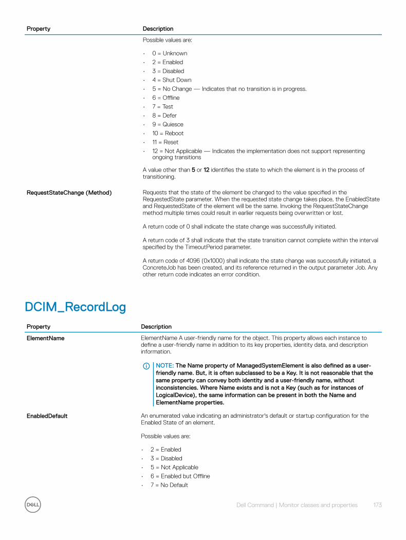
Property Description
Possible values are:
• 0 = Unknown
• 2 = Enabled
• 3 = Disabled
• 4 = Shut Down
• 5 = No Change — Indicates that no transition is in progress.
• 6 = Offline
• 7 = Test
• 8 = Defer
• 9 = Quiesce
• 10 = Reboot
• 11 = Reset
• 12 = Not Applicable — Indicates the implementation does not support representing ongoing transitions
A value other than 5 or 12 identifies the state to which the element is in the process of transitioning.
RequestStateChange (Method) Requests that the state of the element be changed to the value specified in the RequestedState parameter. When the requested state change takes place, the EnabledState and RequestedState of the element will be the same. Invoking the RequestStateChange method multiple times could result in earlier requests being overwritten or lost.
A return code of 0 shall indicate the state change was successfully initiated.
A return code of 3 shall indicate that the state transition cannot complete within the interval specified by the TimeoutPeriod parameter.
A return code of 4096 (0x1000) shall indicate the state change was successfully initiated, a ConcreteJob has been created, and its reference returned in the output parameter Job. Any other return code indicates an error condition.
DCIM_RecordLogProperty Description
ElementName ElementName A user-friendly name for the object. This property allows each instance to define a user-friendly name in addition to its key properties, identity data, and description information.
NOTE: The Name property of ManagedSystemElement is also defined as a user-friendly name. But, it is often subclassed to be a Key. It is not reasonable that the same property can convey both identity and a user-friendly name, without inconsistencies. Where Name exists and is not a Key (such as for instances of LogicalDevice), the same information can be present in both the Name and ElementName properties.
EnabledDefault An enumerated value indicating an administrator's default or startup configuration for the Enabled State of an element.
Possible values are:
• 2 = Enabled
• 3 = Disabled
• 5 = Not Applicable
• 6 = Enabled but Offline
• 7 = No Default
Dell Command | Monitor classes and properties 173
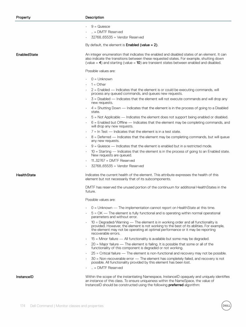
Property Description
• 9 = Quiesce
• .. = DMTF Reserved
• 32768..65535 = Vendor Reserved
By default, the element is Enabled (value = 2).
EnabledState An integer enumeration that indicates the enabled and disabled states of an element. It can also indicate the transitions between these requested states. For example, shutting down (value = 4) and starting (value = 10) are transient states between enabled and disabled.
Possible values are:
• 0 = Unknown
• 1 = Other
• 2 = Enabled — Indicates that the element is or could be executing commands, will process any queued commands, and queues new requests.
• 3 = Disabled — Indicates that the element will not execute commands and will drop any new requests.
• 4 = Shutting Down — Indicates that the element is in the process of going to a Disabled state.
• 5 = Not Applicable — Indicates the element does not support being enabled or disabled.
• 6 = Enabled but Offline — Indicates that the element may be completing commands, and will drop any new requests.
• 7 = In Test — Indicates that the element is in a test state.
• 8 = Deferred — Indicates that the element may be completing commands, but will queue any new requests.
• 9 = Quiesce — Indicates that the element is enabled but in a restricted mode.
• 10 = Starting — Indicates that the element is in the process of going to an Enabled state. New requests are queued.
• 11..32767 = DMTF Reserved
• 32768..65535 = Vendor Reserved
HealthState Indicates the current health of the element. This attribute expresses the health of this element but not necessarily that of its subcomponents.
DMTF has reserved the unused portion of the continuum for additional HealthStates in the future.
Possible values are:
• 0 = Unknown — The implementation cannot report on HealthState at this time.
• 5 = OK — The element is fully functional and is operating within normal operational parameters and without error.
• 10 = Degraded/Warning — The element is in working order and all functionality is provided. However, the element is not working to the best of its abilities. For example, the element may not be operating at optimal performance or it may be reporting recoverable errors.
• 15 = Minor failure — All functionality is available but some may be degraded.
• 20 = Major failure — The element is failing. It is possible that some or all of the functionality of this component is degraded or not working.
• 25 = Critical failure — The element is non-functional and recovery may not be possible.
• 30 = Non-recoverable error — The element has completely failed, and recovery is not possible. All functionality provided by this element has been lost.
• .. = DMTF Reserved
InstanceID Within the scope of the instantiating Namespace, InstanceID opaquely and uniquely identifies an instance of this class. To ensure uniqueness within the NameSpace, the value of InstanceID should be constructed using the following preferred algorithm:
174 Dell Command | Monitor classes and properties
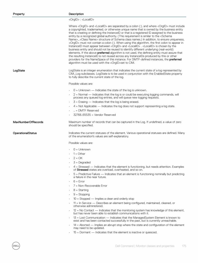
Property Description
<OrgID> : <LocalID>
Where <OrgID> and <LocalID> are separated by a colon (:), and where <OrgID> must include a copyrighted, trademarked, or otherwise unique name that is owned by the business entity that is creating or defining the InstanceID or that is a registered ID assigned to the business entity by a recognized global authority. (This requirement is similar to the <Schema Name>_<Class Name> structure of Schema class names.) In addition, to ensure uniqueness, <OrgID> must not contain a colon (:). When using this algorithm, the first colon to appear in InstanceID must appear between <OrgID> and <LocalID> . <LocalID> is chosen by the business entity and should not be reused to identify different underlying (real-world) elements. If the above preferred algorithm is not used, the defining entity must assure that the resulting InstanceID is not reused across any InstanceIDs produced by this or other providers for the NameSpace of this instance. For DMTF-defined instances, the preferred algorithm must be used with the <OrgID>set to CIM.
LogState LogState is an integer enumeration that indicates the current state of a log represented by CIM_Log subclasses. LogState is to be used in conjunction with the EnabledState property to fully describe the current state of the log.
Possible values are:
• 0 = Unknown — Indicates the state of the log is unknown.
• 2 = Normal — Indicates that the log is or could be executing logging commands, will process any queued log entries, and will queue new logging requests.
• 3 = Erasing — Indicates that the log is being erased.
• 4 = Not Applicable — Indicates the log does not support representing a log state.
• .. = DMTF Reserved
• 32768..65535 = Vendor Reserved
MaxNumberOfRecords Maximum number of records that can be captured in the Log. If undefined, a value of zero should be specified.
OperationalStatus Indicates the current statuses of the element. Various operational statuses are defined. Many of the enumeration's values are self-explanatory.
Possible values are:
• 0 = Unknown
• 1 = Other
• 2 = OK
• 3 = Degraded
• 4 = Stressed — Indicates that the element is functioning, but needs attention. Examples of Stressed states are overload, overheated, and so on.
• 5 = Predictive Failure — Indicates that an element is functioning nominally but predicting a failure in the near future.
• 6 = Error
• 7 = Non-Recoverable Error
• 8 = Starting
• 9 = Stopping
• 10 = Stopped — Implies a clean and orderly stop
• 11 = In Service — Describes an element being configured, maintained, cleaned, or otherwise administered.
• 12 = No Contact — Indicates that the monitoring system has knowledge of this element, but has never been able to establish communications with it.
• 13 = Lost Communication — Indicates that the ManagedSystem Element is known to exist and has been contacted successfully in the past, but is currently unreachable.
• 14 = Aborted — Implies an abrupt stop where the state and configuration of the element may need to be updated.
• 15 = Dormant — Indicates that the element is inactive or quiesced.
Dell Command | Monitor classes and properties 175
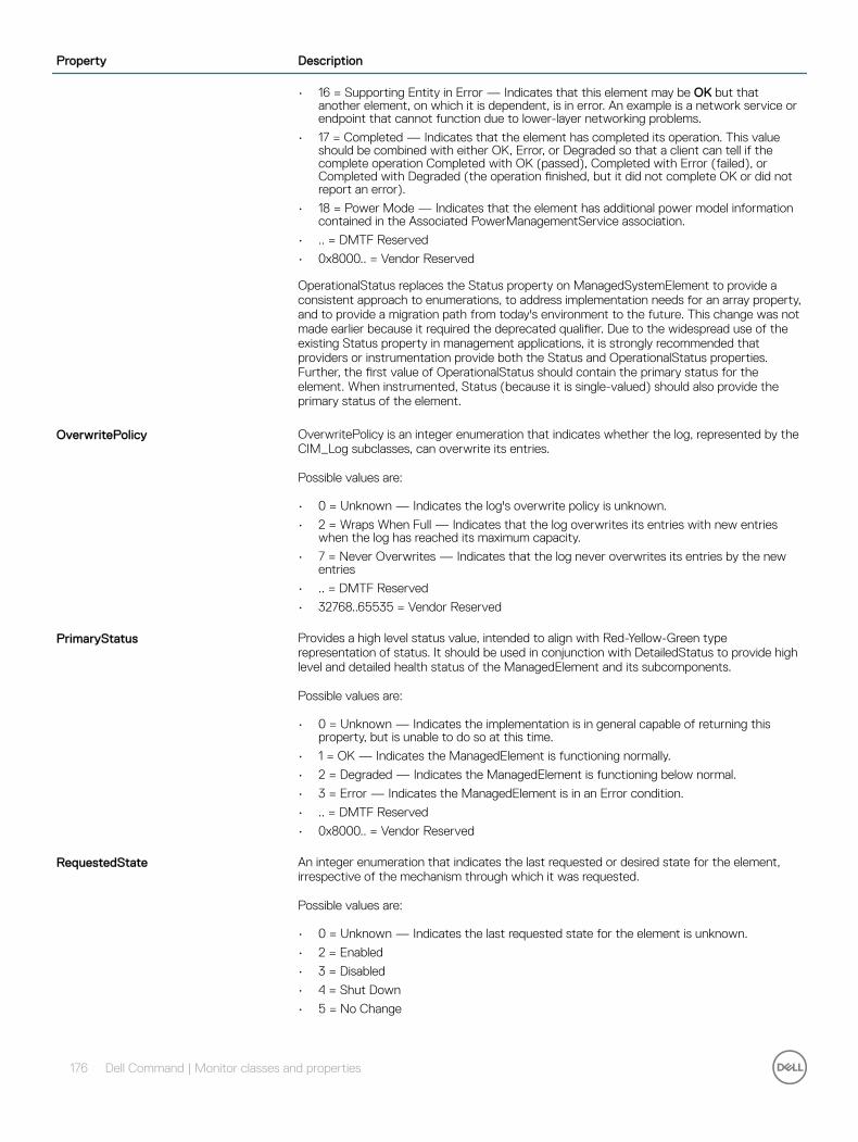
Property Description
• 16 = Supporting Entity in Error — Indicates that this element may be OK but that another element, on which it is dependent, is in error. An example is a network service or endpoint that cannot function due to lower-layer networking problems.
• 17 = Completed — Indicates that the element has completed its operation. This value should be combined with either OK, Error, or Degraded so that a client can tell if the complete operation Completed with OK (passed), Completed with Error (failed), or Completed with Degraded (the operation finished, but it did not complete OK or did not report an error).
• 18 = Power Mode — Indicates that the element has additional power model information contained in the Associated PowerManagementService association.
• .. = DMTF Reserved
• 0x8000.. = Vendor Reserved
OperationalStatus replaces the Status property on ManagedSystemElement to provide a consistent approach to enumerations, to address implementation needs for an array property, and to provide a migration path from today's environment to the future. This change was not made earlier because it required the deprecated qualifier. Due to the widespread use of the existing Status property in management applications, it is strongly recommended that providers or instrumentation provide both the Status and OperationalStatus properties. Further, the first value of OperationalStatus should contain the primary status for the element. When instrumented, Status (because it is single-valued) should also provide the primary status of the element.
OverwritePolicy OverwritePolicy is an integer enumeration that indicates whether the log, represented by the CIM_Log subclasses, can overwrite its entries.
Possible values are:
• 0 = Unknown — Indicates the log's overwrite policy is unknown.
• 2 = Wraps When Full — Indicates that the log overwrites its entries with new entries when the log has reached its maximum capacity.
• 7 = Never Overwrites — Indicates that the log never overwrites its entries by the new entries
• .. = DMTF Reserved
• 32768..65535 = Vendor Reserved
PrimaryStatus Provides a high level status value, intended to align with Red-Yellow-Green type representation of status. It should be used in conjunction with DetailedStatus to provide high level and detailed health status of the ManagedElement and its subcomponents.
Possible values are:
• 0 = Unknown — Indicates the implementation is in general capable of returning this property, but is unable to do so at this time.
• 1 = OK — Indicates the ManagedElement is functioning normally.
• 2 = Degraded — Indicates the ManagedElement is functioning below normal.
• 3 = Error — Indicates the ManagedElement is in an Error condition.
• .. = DMTF Reserved
• 0x8000.. = Vendor Reserved
RequestedState An integer enumeration that indicates the last requested or desired state for the element, irrespective of the mechanism through which it was requested.
Possible values are:
• 0 = Unknown — Indicates the last requested state for the element is unknown.
• 2 = Enabled
• 3 = Disabled
• 4 = Shut Down
• 5 = No Change
176 Dell Command | Monitor classes and properties
Property Description
• 6 = Offline — Indicates that the element has been requested to transition to the Enabled but Offline EnabledState.
• 7 = Test
• 8 = Deferred
• 9 = Quiesce
• 10 = Reboot — Refers to doing a Shut Down and then moving to an Enabled state.
• 11 = Reset — Indicates that the element is first Disabled and then Enabled.
• 12 = Not Applicable
• .. = DMTF Reserved
• 32768..65535 = Vendor Reserved
The actual state of the element is represented by EnabledState. This property is provided to compare the last requested and current enabled or disabled states. Note that when EnabledState is set to 5 (Not Applicable), then this property has no meaning. Refer to the EnabledState property description for explanations of the values in the RequestedState enumeration.
NOTE: The value No Change (5) has been deprecated instead of indicating the last requested state is Unknown (0). If the last requested or desired state is unknown, RequestedState should have the value Unknown (0), but may have the value No Change (5).
There are two new values in RequestedState that build on the statuses of EnabledState. These are Reboot (10) and Reset (11). Shut Down requests an orderly transition to the Disabled state, and may involve removing power, to completely erase any existing state. The Disabled state requests an immediate disabling of the element, such that it will not execute or accept any commands or processing requests.
This property is set as the result of a method invocation (such as Start or StopService on CIM_Service), or can be overridden and defined as WRITEable in a subclass. The method approach is considered superior to a WRITEable property, because it allows an explicit invocation of the operation and the return of a result code.
If knowledge of the last RequestedState is not supported for the EnabledLogicalElement, the property is NULL or has the value 12 Not Applicable.
TransitioningToState Indicates the target state to which the instance is transitioning.
• 0 = Unknown
• 2 = Enabled
• 3 = Disabled
• 4 = Shut Down
• 5 = No Change — ndicates that no transition is in progress.
• 6 = Offline
• 7 = Test
• 8 = Defer
• 9 = Quiesce
• 10 = Reboot
• 11 = Reset
• 12 = Not Applicable — Indicates the implementation does not support representing ongoing transitions.
A value other than 5 or 12 identifies the state to which the element is in the process of transitioning.
Dell Command | Monitor classes and properties 177
DCIM_OperatingSystemProperty Description
CreationClassName Indicates the name of the class or the subclass used in the creation of an instance. When used with the other key properties of this class, this property allows all instances of this class and its subclasses to be uniquely identified.
CSCreationClassName The scoping ComputerSystem's CreationClassName.
CSName The scoping ComputerSystem's Name.
EnabledDefault An enumerated value indicating an administrator's default or startup configuration for the Enabled State of an element.
Possible values are:
• 1 = Other
• 2 = Enabled — Indicates that the element is or could be executing commands, will process any queued commands, and queues new requests.
• 3 = Disabled — Indicates that the element will not execute commands and will drop any new requests.
• 4 = Shutting Down — Indicates that the element is in the process of going to a Disabled state.
• 5 = Not Applicable — Indicates the element does not support being enabled or disabled.
• 6 = Enabled but Offline — Indicates that the element may be completing commands, and will drop any new requests.
• 7 = In Test — Indicates that the element is in a test state.
• 8 = Deferred — Indicates that the element may be completing commands, but will queue any new requests.
• 9 = Quiesce — Indicates that the element is enabled but in a restricted mode.
• 10 = Starting — Indicates that the element is in the process of going to an Enabled state. New requests are queued.
• 11..32767 = DMTF Reserved
• 32768..65535 = Vendor Reserved
By default, the element is Enabled (value = 2).
LastBootUpTime Time when the operating system was last booted.
LocalDateTime Operating system's notion of the local date and time of day.
Name The inherited Name serves as key of an operating system instance within a computer system.
OSType A integer indicating the type of operating system.
Possible values are:
• 0 = Unknown
• 1 = Other
• 2 = MACOS
• 3 = ATTUNIX
• 4 = DGUX
• 5 = DECNT
• 6 = Tru64 UNIX
• 7 = OpenVMS
• 8 = HPUX
178 Dell Command | Monitor classes and properties
Property Description
• 9 = AIX
• 10 = MVS
• 11 = OS400
• 12 = OS/2
• 13 = JavaVM
• 14 = MSDOS
• 15 = WIN3x
• 16 = WIN95
• 17 = WIN98
• 18 = WINNT
• 19 = WINCE
• 20 = NCR3000
• 21 = NetWare
• 22 = OSF
• 23 = DC/OS
• 24 = Reliant UNIX
• 25 = SCO UnixWare
• 26 = SCO OpenServer
• 27 = Sequent
• 28 = IRIX
• 29 = Solaris
• 30 = SunOS
• 31 = U6000
• 32 = ASERIES
• 33 = HP NonStop OS
• 34 = HP NonStop OSS
• 35 = BS2000
• 36 = LINUX
• 37 = Lynx
• 38 = XENIX
• 39 = VM
• 40 = Interactive UNIX
• 41 = BSDUNIX
• 42 = FreeBSD
• 43 = NetBSD
• 44 = GNU Hurd
• 45 = OS9
• 46 = MACH Kernel
• 47 = Inferno
• 48 = QNX
• 49 = EPOC
• 50 = IxWorks
• 51 = VxWorks
• 52 = MiNT
• 53 = BeOS
• 54 = HP MPE
• 55 = NextStep
• 56 = PalmPilot
• 57 = Rhapsody
• 58 = Windows 2000
Dell Command | Monitor classes and properties 179
Property Description
• 59 = Dedicated
• 60 = OS/390
• 61 = VSE
• 62 = TPF
• 63 = Windows (R) Me
• 64 = Caldera Open UNIX
• 65 = OpenBSD
• 66 = Not Applicable
• 67 = Windows XP
• 68 = z/OS
• 69 = Microsoft Windows Server 2003
• 70 = Microsoft Windows Server 2003 64-Bit
• 71 = Windows XP 64-Bit
• 72 = Windows XP Embedded
• 73 = Windows Vista
• 74 = Windows Vista 64-Bit
• 75 = Windows Embedded for Point of Service
• 76 = Microsoft Windows Server 2008
• 77 = Microsoft Windows Server 2008 64-Bit
• 78 = FreeBSD 64-Bit
• 79 = RedHat Enterprise Linux
• 80 = RedHat Enterprise Linux 64-Bit
• 81 = Solaris 64-Bit
• 82 = SUSE
• 83 = SUSE 64-Bit
• 84 = SLES
• 85 = SLES 64-Bit
• 86 = Novell OES
• 87 = Novell Linux Desktop
• 88 = Sun Java Desktop System
• 89 = Mandriva
• 90 = Mandriva 64-Bit
• 91 = TurboLinux
• 92 = TurboLinux 64-Bit
• 93 = Ubuntu
• 94 = Ubuntu 64-Bit
• 95 = Debian
• 96 = Debian 64-Bit
• 97 = Linux 2.4.x
• 98 = Linux 2.4.x 64-Bit
• 99 = Linux 2.6.x
• 100 = Linux 2.6.x 64-Bit
• 101 = Linux 64-Bit
• 102 = Other 64-Bit
• 103 = Microsoft Windows Server 2008 R2
• 104 = VMware ESXi
• 105 = Microsoft Windows 7
• 106 = CentOS 32-bit
• 107 = CentOS 64-bit
• 108 = Oracle Enterprise Linux 32-bit
180 Dell Command | Monitor classes and properties
Property Description
• 109 = Oracle Enterprise Linux 64-bit
• 110 = eComStation 32-bitx
• 111 = Microsoft Windows Server 2011
• 113 = Microsoft Windows Server 2012
• 114 = Microsoft Windows 8
• 115 = Microsoft Windows 8 64-bit
• 116 = Microsoft Windows 8.1
• 117 = Microsoft Windows 8.1 64-bit
• 118 = Microsoft Windows 10
• 119 = Microsoft Windows 10 64-bit
RequestedState An integer enumeration that indicates the last requested or desired state for the element, irrespective of the mechanism through which it was requested.
Possible values are:
• 0 = Unknown — Indicates the last requested state for the element is unknown.
• 2 = Enabled
• 3 = Disabled
• 4 = Shut Down
• 5 = No Change
• 6 = Offline — Indicates that the element has been requested to transition to the Enabled but Offline EnabledState.
• 7 = Test
• 8 = Deferred
• 9 = Quiesce
• 10 = Reboot — Refers to doing a Shut Down and then moving to an Enabled state.
• 11 = Reset - Indicates that the element is first Disabled and then Enabled.
• 12 = Not Applicable
• .. = DMTF Reserved
• 32768..65535 = Vendor Reserved
The actual state of the element is represented by EnabledState. This property is provided to compare the last requested and current enabled or disabled states. Note that when EnabledState is set to 5 (Not Applicable), then this property has no meaning. Refer to the EnabledState property description for explanations of the values in the RequestedState enumeration.
NOTE: The value No Change (5) has been deprecated instead of indicating the last requested state is Unknown (0). If the last requested or desired state is unknown, RequestedState should have the value Unknown (0), but may have the value No Change (5).
There are two new values in RequestedState that build on the statuses of EnabledState. These are Reboot (10) and Reset (11).
Shut Down requests an orderly transition to the Disabled state, and may involve removing power, to completely erase any existing state. The Disabled state requests an immediate disabling of the element, such that it will not execute or accept any commands or processing requests.
This property is set as the result of a method invocation (such as Start or StopService on CIM_Service), or can be overridden and defined as WRITEable in a subclass. The method approach is considered superior to a WRITEable property, because it allows an explicit invocation of the operation and the return of a result code.
If knowledge of the last RequestedState is not supported for the EnabledLogicalElement, the property is NULL or has the value 12 (Not Applicable).
Dell Command | Monitor classes and properties 181

Property Description
TransitioningToState Indicates the target state to which the instance is transitioning.
Possible values are:
• 0 = Unknown
• 2 = Enabled
• 3 = Disabled
• 4 = Shut Down
• 5 = No Change — Indicates that no transition is in progress.
• 6 = Offline
• 7 = Test
• 8 = Defer
• 9 = Quiesce
• 10 = Reboot
• 11 = Reset
• 12 = Not Applicable — Indicates the implementation does not support representing ongoing transitions.
Version A string describing the Operating System's version number. The format of the version information is as follows: <Major Number>.<Minor Number>.<Revision> or <Major Number>.<Minor Number>.<Revision Letter>.
DCIM_SoftwareIdentityProperty Description
ClassificationDescriptions An array of free-form strings providing more detailed explanations for any of the entries in the Classifications array. Note that each entry is related to one in the Classifications array located at the same index.
Classifications An array of enumerated integers that classify this software. For example, the software MAY be instrumentation (value = 5) or firmware and diagnostic software (10 and 7). The use of value 6, Firmware/BIOS, is being deprecated. Instead, either the value 10 (Firmware) and/or 11 (BIOS/FCode) SHOULD be used. The value 13, Software Bundle, identifies a software package consisting of multiple discrete software instances that can be installed individually or together.
Each contained software instance is represented by an instance of SoftwareIdentity that is associated to this instance of SoftwareIdentityinstance via a Component association.
Possible values are:
• 0 = Unknown
• 1 = Other
• 2 = Driver
• 3 = Configuration Software
• 4 = Application Software
• 5 = Instrumentation
• 6 = Firmware/BIOS
• 7 = Diagnostic Software
• 8 = Operating System
• 9 = Middleware
• 10 = Firmware
• 11 = BIOS/FCode
• 12 = Support/Service Pack
182 Dell Command | Monitor classes and properties

Property Description
• 13 = Software Bundle
• .. = DMTF Reserved
• 0x8000..0xFFFF = Vendor Reserved
ElementName A user-friendly name for the object. This property allows each instance to define a user-friendly name in addition to its key properties, identity data, and description information.
NOTE: The Name property of ManagedSystemElement is also defined as a user-friendly name. But, it is often subclassed to be a Key. It is not reasonable that the same property can convey both identity and a user-friendly name, without inconsistencies. Where Name exists and is not a Key (such as for instances of LogicalDevice), the same information can be present in both the Name and ElementName properties.
InstanceID Within the scope of the instantiating Namespace, InstanceID opaquely and uniquely identifies an instance of this class. To ensure uniqueness within the NameSpace, the value of InstanceID should be constructed using the following preferred algorithm:
<OrgID> : <LocalID>
Where <OrgID> and <LocalID> are separated by a colon (:), and where <OrgID> must include a copyrighted, trademarked, or otherwise unique name that is owned by the business entity that is creating or defining the InstanceID or that is a registered ID assigned to the business entity by a recognized global authority. (This requirement is similar to the <Schema Name>_<Class Name> structure of Schema class names.) In addition, to ensure uniqueness, <OrgID> must not contain a colon (:). When using this algorithm, the first colon to appear in InstanceID must appear between <OrgID> and <LocalID> . <LocalID> is chosen by the business entity and should not be reused to identify different underlying (real-world) elements. If the above preferred algorithm is not used, the defining entity must assure that the resulting InstanceID is not reused across any InstanceIDs produced by this or other providers for the NameSpace of this instance. For DMTF-defined instances, the preferred algorithm must be used with the <OrgID>set to CIM.
IsEntity The IsEntity property is used to indicate whether the SoftwareIdentity corresponds to a discrete copy of the software component or is being used to convey descriptive and identifying information about software that is not present in the management domain. A value of TRUE indicates that the SoftwareIdentity instance corresponds to a discrete copy of the software component. A value of FALSE indicates that the SoftwareIdentity instance does not correspond to a discrete copy of the Software.
Manufacturer Manufacturer of this software.
ReleaseDate The date the software was released.
RevisionNumber The revision or maintenance release component of the software's version information. For example, 3 from version 12.1(3)T. This property is defined as a numeric value to allow the determination of newer versus older releases. A newer revision is indicated by a larger numeric value.
TargetTypes An array of strings that describes the compatible installer(s). The purpose of the array elements is to establish compatibility between a SoftwareIdentity and a SoftwareInstallationService that can install the SoftwareIdentity by comparing the values of the array elements of this property to the values of SoftwareInstallationServiceCapabilities.SupportedTargetTypes[] property's array elements.
VersionString A string representing the complete software version information. For example, 12.1(3)T. This string and the numeric major/minor/revision/build properties are complementary. Since vastly different representations and semantics exist for versions, it is not assumed that one representation is sufficient to permit a client to perform computations (i.e., the values are numeric) and a user to recognize the software's version (i.e., the values are understandable and readable). Hence, both numeric and string representations of version are provided.
Dell Command | Monitor classes and properties 183

DCIM_BIOSElementProperty Description
Manufacturer The name used to identify this SoftwareElement. Manufacturer of this SoftwareElement.
Name The name used to identify this SoftwareElement.
ReleaseDate Date that this BIOS was released.
SoftwareElementID This is an identifier for the SoftwareElement and is designed to be used in conjunction with other keys to create a unique representation of the element.
SoftwareElementState The SoftwareElementState is defined in this model to identify various states of a SoftwareElement's life cycle.
Possible values are:
• 0 = Deployable — Describes the details necessary to successfully distribute it and the details (Checks and Actions) required to move it to the installable state (i.e, the next state).
• 1 = Installable — Describes the details necessary to successfully install it and the details (Checks and Actions) required to create an element in the executable state (i.e., the next state).
• 2 = Executable — Describes the details necessary to successfully start it and the details (Checks and Actions) required to move it to the running state (i.e., the next state).
• 3 = Running — Describes the details necessary to manage the started element.
TargetOperatingSystem The TargetOperatingSystem property specifies the element's operating system environment. The value of this property does not ensure that it is binary executable. Two other pieces of information are needed. First, the version of the OS needs to be specified using the class, CIM_OSVersion Check. The second piece of information is the architecture that the OS runs on. This information is verified using CIM_ArchitectureCheck. The combination of these constructs clearly identifies the level of OS required for a particular SoftwareElement.
Possible values are:
• 0 = Unknown
• 1 = Other
• 2 = MACOS
• 3 = ATTUNIX
• 4 = DGUX
• 5 = DECNT
• 6 = Tru64 UNIX
• 7 = OpenVMS
• 8 = HPUX
• 9 = AIX
• 10 = MVS
• 11 = OS400
• 12 = OS/2
• 13 = JavaVM
• 14 = MSDOS
• 15 = WIN3x
• 16 = WIN95
• 17 = WIN98
• 18 = WINNT
• 19 = WINCE
184 Dell Command | Monitor classes and properties
Property Description
• 20 = NCR3000
• 21 = NetWare
• 22 = OSF
• 23 = DC/OS
• 24 = Reliant UNIX
• 25 = SCO UnixWare
• 26 = SCO OpenServer
• 27 = Sequent
• 28 = IRIX
• 29 = Solaris
• 30 = SunOS
• 31 = U6000
• 32 = ASERIES
• 33 = HP NonStop OS
• 34 = HP NonStop OSS
• 35 = BS2000
• 36 = LINUX
• 37 = Lynx
• 38 = XENIX
• 39 = VM
• 40 = Interactive UNIX
• 41 = BSDUNIX
• 42 = FreeBSD
• 43 = NetBSD
• 44 = GNU Hurd
• 45 = OS9
• 46 = MACH Kernel
• 47 = Inferno
• 48 = QNX
• 49 = EPOC
• 50 = IxWorks
• 51 = VxWorks
• 52 = MiNT
• 53 = BeOS
• 54 = HP MPE
• 55 = NextStep
• 56 = PalmPilot
• 57 = Rhapsody
• 58 = Windows 2000
• 59 = Dedicated
• 60 = OS/390
• 61 = VSE
• 62 = TPF
• 63 = Windows (R) Me
• 64 = Caldera Open UNIX
• 65 = OpenBSD
• 66 = Not Applicable
• 67 = Windows XP
• 68 = z/OS
• 69 = Microsoft Windows Server 2003
Dell Command | Monitor classes and properties 185
Property Description
• 70 = Microsoft Windows Server 2003 64-Bit
• 71 = Windows XP 64-Bit
• 72 = Windows XP Embedded
• 73 = Windows Vista
• 74 = Windows Vista 64-Bit
• 75 = Windows Embedded for Point of Service
• 76 = Microsoft Windows Server 2008
• 77 = Microsoft Windows Server 2008 64-Bit
Version Displays the version of the BIOS.
DCIM_ConcreteJobProperty Description
Description Provides a textual description of the object.
ErrorCode A vendor-specific error code. The value must be set to zero if the Job completed without error. Note that this property is also present in the JobProcessingStatistics class. This class is necessary to capture the processing information for recurring Jobs, because only the 'last' run error can be stored in this single-valued property.
ErrorDescription A free-form string that contains the vendor error description. Note that this property is also present in the JobProcessingStatistics class. This class is necessary to capture the processing information for recurring Jobs, because only the last run error can be stored in this single-valued property.
InstanceID Within the scope of the instantiating Namespace, InstanceID opaquely and uniquely identifies an instance of this class. To ensure uniqueness within the NameSpace, the value of InstanceID should be constructed using the following preferred algorithm:
<OrgID> : <LocalID>
Where <OrgID> and <LocalID> are separated by a colon (:), and where <OrgID> must include a copyrighted, trademarked, or otherwise unique name that is owned by the business entity that is creating or defining the InstanceID or that is a registered ID assigned to the business entity by a recognized global authority. (This requirement is similar to the <Schema Name>_<Class Name> structure of Schema class names.) In addition, to ensure uniqueness, <OrgID> must not contain a colon (:). When using this algorithm, the first colon to appear in InstanceID must appear between <OrgID> and <LocalID> . <LocalID> is chosen by the business entity and should not be reused to identify different underlying (real-world) elements. If the above preferred algorithm is not used, the defining entity must assure that the resulting InstanceID is not reused across any InstanceIDs produced by this or other providers for the NameSpace of this instance. For DMTF-defined instances, the preferred algorithm must be used with the <OrgID>set to CIM.
JobRunTimes The number of times that the Job should be run. A value of 1 indicates that the Job is not recurring, while any non-zero value indicates a limit to the number of times that the Job will recur. Zero indicates that there is no limit to the number of times that the Job can be processed, but that it is terminated either after the UntilTime or by manual intervention. By default, a Job is processed once.
JobStatus A free-form string that represents the status of the job. The primary status is reflected in the inherited OperationalStatus property. JobStatus provides additional, implementation-specific details.
186 Dell Command | Monitor classes and properties

Property Description
Name The user-friendly name for this instance of a Job. In addition, the user-friendly name can be used as a property for a search or query.
NOTE: Name does not have to be unique within a namespace.
Priority Indicates the urgency or importance of execution of the Job. The lower the number, the higher the priority. Note that this property is also present in the JobProcessingStatistics class. This class is necessary to capture the setting information that would influence the results of a job.
TimeBeforeRemoval The amount of time that the Job is retained after it has finished executing, either succeeding or failing in that execution. The job must remain in existence for some period of time regardless of the value of the DeleteOnCompletion property. The default is five minutes.
DCIM_BootSourceSettingProperty Description
BIOSBootString A string identifying the boot source which corresponds to the string used by the BIOS to uniquely name the boot source. For example, in systems which implement the BIOS Boot Specification, the string could correspond to the descString string for entries in the IPL Table or BCV Table.
ElementName The user-friendly name for this instance of SettingData. In addition, the user-friendly name can be used as an index property for a search or query.
NOTE: The name does not have to be unique within a namespace.
FailThroughSupported An enumeration indicating the behavior when the attempt to boot using the boot source fails (no media, timeout).
Possible values are:
• 0 = Unknown
• 1 = Is Supported — Indicates that next boot source the boot order is used.
• 2 = Not Supported — Indicates that the boot order is terminated and no other boot sources associated to the same CIM_BootConfigSetting are used).
The default value is 1 (is supported).
InstanceID Within the scope of the instantiating Namespace, InstanceID opaquely and uniquely identifies an instance of this class. To ensure uniqueness within the NameSpace, the value of InstanceID should be constructed using the following preferred algorithm: <OrgID> : <LocalID> Where <OrgID> and <LocalID> are separated by a colon (:), and where <OrgID> must include a copyrighted, trademarked, or otherwise unique name that is owned by the business entity that is creating or defining the InstanceID or that is a registered ID assigned to the business entity by a recognized global authority. (This requirement is similar to the <Schema Name>_<Class Name> structure of Schema class names.) In addition, to ensure uniqueness, <OrgID> must not contain a colon (:). When using this algorithm, the first colon to appear in InstanceID must appear between <OrgID> and <LocalID>. <LocalID> is chosen by the business entity and should not be reused to identify different underlying (real-world) elements. If the above preferred algorithm is not used, the defining entity must assure that the resulting InstanceID is not reused across any InstanceIDs produced by this or other providers for the NameSpace of this instance. For DMTF-defined instances, the preferred algorithm must be used with the <OrgID> set to CIM.
StructuredBootString A string identifying the boot source using the format <OrgID>:<identifier>:<index>, in which neither<OrgID>, <identifier> or <index> contains a colon (:). The value of <OrgID>is a
Dell Command | Monitor classes and properties 187
Property Description
copyrighted, trademarked or otherwise unique name that is owned by the entity defining the <identifier>, or is a registered ID that is assigned to the entity by a recognized global authority. For DMTF defined identifiers, the <OrgID> is set to CIM.
The <identifiers> are:
• Floppy
• Hard-Disk
• CD/DVD
• Network
• PCMCIA
• USB
The value of <index> is a non-zero integer.
DCIM_BootConfigSettingProperty Description
ElementName The user-friendly name for this instance of SettingData. In addition, the user-friendly name can be used as an index property for a search or query.
NOTE: The name does not have to be unique within a namespace.
InstanceID Within the scope of the instantiating Namespace, InstanceID opaquely and uniquely identifies an instance of this class. To ensure uniqueness within the NameSpace, the value of InstanceID should be constructed using the following preferred algorithm: <OrgID> : <LocalID> Where <OrgID> and <LocalID> are separated by a colon (:), and where <OrgID> must include a copyrighted, trademarked, or otherwise unique name that is owned by the business entity that is creating or defining the InstanceID or that is a registered ID assigned to the business entity by a recognized global authority. (This requirement is similar to the <Schema Name>_<Class Name>structure of Schema class names.) In addition, to ensure uniqueness, <OrgID> must not contain a colon (:). When using this algorithm, the first colon to appear in InstanceID must appear between <OrgID> and <LocalID>. <LocalID> is chosen by the business entity and should not be reused to identify different underlying (real-world) elements. If the above preferred algorithm is not used, the defining entity must assure that the resulting InstanceID is not reused across any InstanceIDs produced by this or other providers for the NameSpace of this instance. For DMTF-defined instances, the preferred algorithm must be used with the <OrgID> set to CIM.
ChangeBootOrder (Method) This method is called to change the boot order within a boot configuration. An ordered array of BootSourceSetting instances is passed to this method. Each BootSourceSetting instance MUST already be associated with this BootConfigSetting instance via an instance of OrderedComponent. If not, the implementation MUST return a value of Invalid Parameter. Upon execution of this method, the value of the AssignedSequence property on each instance of OrderedComponent will be updated such that the values are monotonically increasing in correlation with the position of the referenced BootSourceSetting instance in the source input parameter. That is, the first position in the array will have the lowest value for AssignedSequence. The second position will have the second lowest value, and so on. For BootSourceSetting instances which are associated with the BootConfigSetting instance via OrderedComponent and not present in the input array, the AssignedSequence property on the OrderedComponent association will be assigned a value of 0.
188 Dell Command | Monitor classes and properties

DCIM_IPAssignmentSettingDataProperty Description
AddressOrigin AddressOrigin identifies the method by which the IP Address, Subnet Mask, and Gateway were assigned to the IPProtocolEndpoint.
Possible values are:
• 0 = Unknown
• 1 = Other
• 2 = Not Applicable — Indicates that the application of the IPAssignmentSettingData instance does not affect these properties.
• 3 = Static — Indicates that values for the properties are contained in the IPAssignmentSettingData instance.
• 4 = DHCP — Indicates that the values will be assigned via DHCP.
• 5 = BOOTP — Indicates that the values will be assigned via BOOTP.
• 6..32767 = DMTF Reserved
• 32768.. = Vendor Reserved
ElementName The user-friendly name for this instance of SettingData. In addition, the user-friendly name can be used as an index property for a search or query.
NOTE: The name does not have to be unique within a namespace.
InstanceID Within the scope of the instantiating Namespace, InstanceID opaquely and uniquely identifies an instance of this class. To ensure uniqueness within the NameSpace, the value of InstanceID should be constructed using the following preferred algorithm:
<OrgID> : <LocalID>
Where <OrgID> and <LocalID> are separated by a colon (:), and where <OrgID> must include a copyrighted, trademarked, or otherwise unique name that is owned by the business entity that is creating or defining the InstanceID or that is a registered ID assigned to the business entity by a recognized global authority. (This requirement is similar to the <Schema Name>_<Class Name> structure of Schema class names.) In addition, to ensure uniqueness, <OrgID> must not contain a colon (:). When using this algorithm, the first colon to appear in InstanceID must appear between <OrgID> and <LocalID> . <LocalID> is chosen by the business entity and should not be reused to identify different underlying (real-world) elements. If the above preferred algorithm is not used, the defining entity must assure that the resulting InstanceID is not reused across any InstanceIDs produced by this or other providers for the NameSpace of this instance. For DMTF-defined instances, the preferred algorithm must be used with the <OrgID>set to CIM.
DCIM_PowerAllocationSettingDataProperty Description
ElementName The user-friendly name for this instance of SettingData. In addition, the user-friendly name can be used as an index property for a search or query.
NOTE: The name does not have to be unique within a namespace.
InstanceID Within the scope of the instantiating Namespace, InstanceID opaquely and uniquely identifies an instance of this class. To ensure uniqueness within the NameSpace, the value of InstanceID should be constructed using the following preferred algorithm:
Dell Command | Monitor classes and properties 189

Property Description
<OrgID> : <LocalID>
Where <OrgID> and <LocalID> are separated by a colon (:), and where <OrgID> must include a copyrighted, trademarked, or otherwise unique name that is owned by the business entity that is creating or defining the InstanceID or that is a registered ID assigned to the business entity by a recognized global authority. (This requirement is similar to the <Schema Name>_<Class Name> structure of Schema class names.) In addition, to ensure uniqueness, <OrgID> must not contain a colon (:). When using this algorithm, the first colon to appear in InstanceID must appear between <OrgID> and <LocalID> . <LocalID> is chosen by the business entity and should not be reused to identify different underlying (real-world) elements. If the above preferred algorithm is not used, the defining entity must assure that the resulting InstanceID is not reused across any InstanceIDs produced by this or other providers for the NameSpace of this instance. For DMTF-defined instances, the preferred algorithm must be used with the <OrgID>set to CIM.
Limit This property specifies the upper bound, or maximum amount of resource that is granted for this allocation. For example, a system which supports memory paging may support setting the Limit of a Memory allocation below that of the VirtualQuantity, thus forcing paging to occur for this allocation.
PowerAllocationSettingPurpose When power is consumed by or allocated to a ManagedSystemElement, there may be well-known or meaningful levels of allocation or consumption for the ManagedSystemElement. The PowerAllocationSettingPurpose property may be used to identify the well known level or provide context for the interpretation of the other values of the PowerAllocationSettingData instance. A value of MaxConAuxiliary indicates that the instance provides information about the maximum power allocated or consumed by the ManagedSystemElement as currently configured, while the ManagedSystemElement is turned off and drawing auxiliary power. Note that an alternate name for auxiliary power is trickle power.
Possible values are:
• 1 = Other
• 2 = MaxConAuxiliary
• 3 = MinWhenOn — Indicates the instance provides information about the minimum value for power consumption for which a configuration of the ManagedSystemElement exists such that when it is powered on and operating in that configuration, the power consumption of the ManagedSystemElement is guaranteed not to exceed the specified amount.
• 4 = MaxAsConfigured — Indicates that the instance provides information about the maximum power that may be allocated to or consumed by the ManagedSystemElement as currently configured while powered on. The actual power consumed may be less.
• 5 = MaxIfAllHotPlug — Indicates that the instance provides information about the maximum power allocated or consumed by the ManagedSystemElement if all components that could be added to the ManagedSystemElement without requiring a power cycle of the ManagedSystemElement were added to the ManagedSystemElement.
• 6 = MaxIfAllColdPlug — Indicates that the instance provides information about the maximum power allocated or consumed by the ManagedSystemElement if all components that could be added to the ManagedSystemElement, including those that require a power cycle of the ManagedSystemElement, were added to the ManagedSystemElement.
• 7 = Allocated — Indicates that the instance provides information about the current power allocated to the ManagedSystemElement.
• 8 = MinWithoutDegradation — Indicates that the instance provides information about the minimum power allocated or consumed by the ManagedSystemElement without causing performance degradation.
• .. = DMTF Reserved
• 32768..65535 = Vendor Reserved
ResourceType The type of resource this allocation setting represents.
190 Dell Command | Monitor classes and properties

Property Description
Possible values are:
• 1 = Other
• 2 = Computer System
• 3 = Processor
• 4 = Memory
• 5 = IDE Controller
• 6 = Parallel SCSI HBA
• 7 = FC HBA
• 8 = iSCSI HBA
• 9 = IB HCA
• 10 = Ethernet Adapter
• 11 = Other Network Adapter
• 12 = I/O Slot
• 13 = I/O Device
• 14 = Floppy Drive
• 15 = CD Drive
• 16 = DVD drive
• 17 = Disk Drive
• 18 = Tape Drive
• 19 = Storage Extent
• 20 = Other storage device
• 21 = Serial port
• 22 = Parallel port
• 23 = USB Controller
• 24 = Graphics controller
• 25 = IEEE 1394 Controller
• 26 = Partitionable Unit
• 27 = Base Partitionable Unit
• 28 = Power
• 29 = Cooling Capacity
• 30 = Ethernet Switch Port
• 31 = Logical Disk
• 32 = Storage Volume
• 33 = Ethernet Connection
• .. = DMTF reserved
• 0x8000..0xFFFF = Vendor Reserved
DCIM_AssetAcquisitionProperty Description
CostCenter Identifying information for the accounting unit withinthe purchasing company that authorized the purchase.
ElementName The user-friendly name for this instance of SettingData. In addition, the user-friendly name can be used as an index property for a search or query.
NOTE: The name does not have to be unique within a namespace.
InstallationDate Date the system was put into service by the purchasing company.
Dell Command | Monitor classes and properties 191

Property Description
InstanceID Within the scope of the instantiating Namespace, InstanceID opaquely and uniquely identifies an instance of this class. To ensure uniqueness within the NameSpace, the value of InstanceID should be constructed using the following preferred algorithm:
<OrgID> : <LocalID>
Where <OrgID> and <LocalID> are separated by a colon (:), and where <OrgID> must include a copyrighted, trademarked, or otherwise unique name that is owned by the business entity that is creating or defining the InstanceID or that is a registered ID assigned to the business entity by a recognized global authority. (This requirement is similar to the <Schema Name>_<Class Name> structure of Schema class names.) In addition, to ensure uniqueness, <OrgID> must not contain a colon (:). When using this algorithm, the first colon to appear in InstanceID must appear between <OrgID> and <LocalID> .<LocalID> is chosen by the business entity and should not be reused to identify different underlying (real-world) elements. If the above preferred algorithm is not used, the defining entity must assure that the resulting InstanceID is not reused across any InstanceIDs produced by this or other providers for the NameSpace of this instance. For DMTF-defined instances, the preferred algorithm must be used with the <OrgID> set to CIM.
PurchaseCost The Purchase Cost field accepts whole numbers only.Entering commas, decimal points, or dollar signsresults in an error message. Value expressed in currency unit that was paid for the system, for example, 25000.
Possible values are:
• 0..32767 = DMTF Reserved
• 32768..65535 = Vendor Reserved
PurchaseDate Date the transaction for acquiring the system was completed.
ReferenceToDeliverySlip Identifying information for the waybill or delivery slip, such as a waybill number.
Possible values are:
• 0..32767 = DMTF Reserved
• 32768..65535 = Vendor Reserved
ReferenceToPONumber Number of the purchase order that authorized buying the system.
Possible values are:
• 0..32767 = DMTF Reserved
• 32768..65535 = Vendor Reserved
DCIM_AssetExtendedWarrantyInformationProperty Description
Cost Displays the total cost of the warranty service on a system.
Possible values are:
• 0..32767 = DMTF Reserved
• 32768..65535 = Vendor Reserved
ElementName The user-friendly name for this instance of SettingData. In addition, the user-friendly name can be used as an index property for a search or query.
NOTE: The name does not have to be unique within a namespace.
192 Dell Command | Monitor classes and properties
Property Description
EndDate Displays the date that extended warranty service ends.
InstanceID Within the scope of the instantiating Namespace, InstanceID opaquely and uniquely identifies an instance of this class. To ensure uniqueness within the NameSpace, the value of InstanceID should be constructed using the following preferred algorithm:
<OrgID> : <LocalID>
Where <OrgID> and <LocalID> are separated by a colon (:), and where <OrgID> must include a copyrighted, trademarked, or otherwise unique name that is owned by the business entity that is creating or defining the InstanceID or that is a registered ID assigned to the business entity by a recognized global authority. (This requirement is similar to the <Schema Name>_<Class Name> structure of Schema class names.) In addition, to ensure uniqueness, <OrgID> must not contain a colon (:). When using this algorithm, the first colon to appear in InstanceID must appear between <OrgID> and <LocalID>. <LocalID> is chosen by the business entity and should not be reused to identify different underlying (real-world) elements. If the above preferred algorithm is not used, the defining entity must assure that the resulting InstanceID is not reused across any InstanceIDs produced by this or other providers for the NameSpace of this instance. For DMTF-defined instances, the preferred algorithm must be used with the <OrgID> set to CIM.
ProviderName Displays the name of the business that is providing warranty service to the system owner.
StartDate Displays the date that extended warranty service begins. This date usually follows the standard warranty service.
DCIM_AssetOwnerInformationProperty Description
ElementName The user-friendly name for this instance of SettingData. In addition, the user-friendly name can be used as an index property for a search or query.
NOTE: The name does not have to be unique within a namespace.
InstanceID Within the scope of the instantiating Namespace, InstanceID opaquely and uniquely identifies an instance of this class. To ensure uniqueness within the NameSpace, the value of InstanceID should be constructed using the following preferred algorithm:
<OrgID> : <LocalID>
Where <OrgID> and <LocalID> are separated by a colon (:), and where <OrgID> must include a copyrighted, trademarked, or otherwise unique name that is owned by the business entity that is creating or defining the InstanceID or that is a registered ID assigned to the business entity by a recognized global authority. (This requirement is similar to the <Schema Name>_<Class Name> structure of Schema class names.) In addition, to ensure uniqueness, <OrgID> must not contain a colon (:). When using this algorithm, the first colon to appear in InstanceID must appear between <OrgID> and <LocalID> . <LocalID> is chosen by the business entity and should not be reused to identify different underlying (real-world) elements. If the above preferred algorithm is not used, the defining entity must assure that the resulting InstanceID is not reused across any InstanceIDs produced by this or other providers for the NameSpace of this instance. For DMTF-defined instances, the preferred algorithm must be used with the <OrgID>set to CIM.
InsuranceCompany The company that insures the system against theft or other loss.
OwnerName The individual or business entity that holds legal title to the system.
Dell Command | Monitor classes and properties 193
Property Description
Type The individual or business entity that holds legal title to the system. Type Whether the system is owned, rented, leased, managed by transfer, or off-lease.
Possible values are:
• 0 = Owned
• 1 = Leased
• 3 = Rented
• 4 = Off Lease
• 5..32767 = Transfer
• 32768..65535 = DMTF Reserved
SetAssetOwnerInformation (Method) This method allows the user to change the Insurance Company and Owner Name of the system.
DCIM_AssetSupportInformationProperty Description
AutomaticFix Method used to fix the problem.
ElementName The user-friendly name for this instance of SettingData. In addition, the user-friendly name can be used as an index property for a search or query.
NOTE: The name does not have to be unique within a namespace.
HelpDesk Name of the help desk that provides technical support for your system;information provided by the help desk.
InstanceID Within the scope of the instantiating Namespace, InstanceID opaquely and uniquely identifies an instance of this class. To ensure uniqueness within the NameSpace, the value of InstanceID should be constructed using the following preferred algorithm:
<OrgID>:<LocalID>
Where <OrgID> and <LocalID> are separated by a colon (:), and where <OrgID> must include a copyrighted, trademarked, or otherwise unique name that is owned by the business entity that is creating or defining the InstanceID or that is a registered ID assigned to the business entity by a recognized global authority. (This requirement is similar to the <Schema Name>_<Class Name> structure of Schema class names.) In addition, to ensure uniqueness, <OrgID> must not contain a colon (:). When using this algorithm, the first colon to appear in InstanceID must appear between <OrgID> and <LocalID>. <LocalID> is chosen by the business entity and should not be reused to identify different underlying (real-world) elements. If the above preferred algorithm is not used, the defining entity must assure that the resulting InstanceID is not reused across any InstanceIDs produced by this or other providers for the NameSpace of this instance. For DMTF-defined instances, the preferred algorithm must be used with the <OrgID> set to CIM.
Outsourced Indicates whether you have contracted with an outside business entity to provide technical support for your system.
Type Indicates whether a support request is for a problem with your system's network connectivity or with a particular system component.
Possible values are:
• 0 = Network
• 1 = Storage
• 2..32767 = DMTF Reserved
194 Dell Command | Monitor classes and properties

Property Description
• 32768..65535 = Vendor Reserved
DCIM_AssetWarrantyInformationProperty Description
Cost The total cost of the warranty service on a system.
Possible values are:
• 0..32767 = DMTF Reserved
• 32768..65535 = Vendor Reserved
Duration The number of days or months that the warranty is to be in force.
Possible values are:
• 0..32767 = DMTF Reserved
• 32768..65535 = Vendor Reserved
ElementName The user-friendly name for this instance of SettingData. In addition, the user-friendly name can be used as an index property for a search or query.
NOTE: The name does not have to be unique within a namespace.
EndDate The date that extended warranty service ends.
InstanceID Within the scope of the instantiating Namespace, InstanceID opaquely and uniquely identifies an instance of this class. To ensure uniqueness within the NameSpace, the value of InstanceID should be constructed using the following preferred algorithm:
<OrgID> : <LocalID>
Where <OrgID> and <LocalID> are separated by a colon (:), and where <OrgID> must include a copyrighted, trademarked, or otherwise unique name that is owned by the business entity that is creating or defining the InstanceID or that is a registered ID assigned to the business entity by a recognized global authority. (This requirement is similar to the <Schema Name>_<Class Name> structure of Schema class names.) In addition, to ensure uniqueness, <OrgID> must not contain a colon (:). When using this algorithm, the first colon to appear in InstanceID must appear between <OrgID> and <LocalID>. <LocalID> is chosen by the business entity and should not be reused to identify different underlying (real-world) elements. If the above preferred algorithm is not used, the defining entity must assure that the resulting InstanceID is not reused across any InstanceIDs produced by this or other providers for the NameSpace of this instance. For DMTF-defined instances, the preferred algorithm must be used with the <OrgID> set to CIM.
UnitType Indicates whether the length of the warranty is measured in days or months.
Possible values are:
• 0 = Days
• 1 = Months
• 2..32767 = DMTF Reserved
• 32768..65535 = Vendor Reserved
Dell Command | Monitor classes and properties 195
DCIM_AssetSystemInformationProperty Description
ChassisAssetTag Chassis Asset Tag of the system.
ElementName The user-friendly name for this instance of SettingData. In addition, the user-friendly name can be used as an index property for a search or query.
NOTE: The name does not have to be unique within a namespace.
InstanceID Within the scope of the instantiating Namespace, InstanceID opaquely and uniquely identifies an instance of this class. To ensure uniqueness within the NameSpace, the value of InstanceID should be constructed using the following preferred algorithm:
<OrgID> : <LocalID>
Where <OrgID> and <LocalID> are separated by a colon (:), and where <OrgID> must include a copyrighted, trademarked, or otherwise unique name that is owned by the business entity that is creating or defining the InstanceID or that is a registered ID assigned to the business entity by a recognized global authority. (This requirement is similar to the <Schema Name>_<Class Name>structure of Schema class names.) In addition, to ensure uniqueness, <OrgID> must not contain a colon (:). When using this algorithm, the first colon to appear in InstanceID must appear between <OrgID> and <LocalID>. <LocalID> chosen by the business entity and should not be reused to identify different underlying (real-world) elements. If the above preferred algorithm is not used, the defining entity must assure that the resulting InstanceID is not reused across any InstanceIDs produced by this or other providers for the NameSpace of this instance. For DMTF-defined instances, the preferred algorithm must be used with the <OrgID> set to CIM.
PrimaryUserName Text that provides the name for the person responsible for managing the system.
PrimaryUserPhone Telephone number for the person responsible for managing the system.
SystemLocation Alphanumeric text that specifies where the system is, such as building and room.
SystemName Alphanumeric text that uniquely identifies the system.
DCIM_AMTSettingsProperty Description
AMTSupported Defines if Intel AMT is supported.
Description Provides a textual description of the object.
IDEREnabled Defines if IDE redirection is enabled.
InstanceID Within the scope of the instantiating Namespace, InstanceID opaquely and uniquely identifies an instance of this class. To ensure uniqueness within the NameSpace, the value of InstanceID should be constructed using the following preferred algorithm:
<OrgID> : <LocalID>
Where <OrgID> and <LocalID> are separated by a colon (:), and where <OrgID> must include a copyrighted, trademarked, or otherwise unique name that is owned by the business entity that is creating or defining the InstanceID or that is a registered ID assigned
196 Dell Command | Monitor classes and properties

Property Description
to the business entity by a recognized global authority. (This requirement is similar to the <Schema Name>_<Class Name> structure of Schema class names.) In addition, to ensure uniqueness, <OrgID> must not contain a colon (:). When using this algorithm, the first colon to appear in InstanceID must appear between <OrgID> and <LocalID>. <LocalID> is chosen by the business entity and should not be reused to identify different underlying (real-world) elements. If the above preferred algorithm is not used, the defining entity must assure that the resulting InstanceID is not reused across any InstanceIDs produced by this or other providers for the NameSpace of this instance. For DMTF-defined instances, the preferredalgorithm must be used with the <OrgID> set to CIM.
SOLEnabled Defines if Serial Over LAN capability is enabled.
DCIM_ASFSettingsProperty Description
ASFEnabled Defines if Intel ASF is enabled.
Description Provides a textual description of the object.
InstanceID Within the scope of the instantiating Namespace, InstanceID opaquely and uniquely identifies an instance of this class. To ensure uniqueness within the NameSpace, the value of InstanceID should be constructed using the following preferred algorithm: <OrgID>:<LocalID>
Where <OrgID> and <LocalID> are separated by a colon (:), and where <OrgID> must include a copyrighted, trademarked, or otherwise unique name that is owned by the business entity that is creating or defining the InstanceID or that is a registered ID assigned to the business entity by a recognized global authority. (This requirement is similar to the structure of Schema class names.) In addition, to ensure uniqueness, <OrgID> must not contain a colon (:). When using this algorithm, the first colon to appear in InstanceID must appear between <OrgID> and <LocalID>. <LocalID> is chosen by the business entity and should not be reused to identify different underlying (real-world) elements. If the above preferred algorithm is not used, the defining entity must assure that the resulting InstanceID is not reused across any InstanceIDs produced by this or other providers for the NameSpace of this instance. For DMTF-defined instances, the preferred algorithm must be used with the <OrgID> set to CIM.
StructureVersion Defines the version of the Intel ASF structure.
DCIM_VProSettingsProperty Description
BIOSSupportedMaximumVAVersion Defines the maximum VA version supported by the BIOS. A value of 0 means the the highest version supported by BIOS is VA 2.6. A value of 1 means the the highest version supported by BIOS is VA 3.0.
Description Provides a textual description of the object.
ElementName The user-friendly name for this instance of SettingData. In addition, the user-friendly name can be used as an index property for a search or query.
NOTE: The name does not have to be unique within a namespace.
Dell Command | Monitor classes and properties 197

Property Description
InstanceID Within the scope of the instantiating Namespace, InstanceID opaquely and uniquely identifies an instance of this class. To ensure uniqueness within the NameSpace, the value of InstanceID should be constructed using the following preferred algorithm:
<OrgID> : <LocalID>
Where <OrgID> and <LocalID> are separated by a colon (:), and where <OrgID> must include a copyrighted, trademarked, or otherwise unique name that is owned by the business entity that is creating or defining the InstanceID or that is a registered ID assigned to the business entity by a recognized global authority. (This requirement is similar to the <Schema Name>_<Class Name> structure of Schema class names.) In addition, to ensure uniqueness, <OrgID> must not contain a colon (:). When using this algorithm, the first colon to appear in InstanceID must appear between <OrgID> and <LocalID> . <LocalID> is chosen by the business entity and should not be reused to identify different underlying (real-world) elements. If the above preferred algorithm is not used, the defining entity must assure that the resulting InstanceID is not reused across any InstanceIDs produced by this or other providers for the NameSpace of this instance. For DMTF-defined instances, the preferred algorithm must be used with the <OrgID>set to CIM.
LTTXTEnabledState Defines CPU LT/TXT enabled state for vPro brand.
Possible values are:
• 2 = Enabled
• 3 = Disabled
• .. = DMTF Reserved
• 32768..65535 = Vendor Reserved
SMXState Defines CPU SMX state for vPro brand.
Possible values are:
• 2 = Enabled
• 3 = Disabled
• .. = DMTF Reserved
• 32768..65535 = Vendor Reserved
SPIFlashhasPlatformDataRegionReserved
Defines if SPI flash has a platform data region reserved.
Possible values are:
• 2 = Enabled
• 3 = Disabled
• .. = DMTF Reserved
• 32768..65535 = Vendor Reserved
SupportedBIOSsetup SupportedBIOSsetup defines if BIOS setup properties are supported.
Possible values are:
• 2 = SupportsMEinBIOSSetup — Defines if ME is supported in BIOS setup.
• 3 = SupportsTPMinBIOSSetup — Defines if TPM is supported in BIOS setup.
• 4 = SupportsTXTinBIOSSetup — Defines if TXT is supported in BIOS setup.
• 5 = SupportsVAExtensions — Defines if VA extensions are supported by the BIOS.
• 6 = SupportsVTdinBIOSSetup — Defines if VT-d is supported in BIOS setup.
• 7 = SupportsVTxinBIOSSetup — Defines if VT-x is supported in BIOS setup
• .. = DMTF Reserved
• 32768..65535 = Vendor Reserved
198 Dell Command | Monitor classes and properties
Property Description
TXTStateInMCHState Defines TXT state in MCH for vPro brand.
Possible values are:
• 2 = Enabled
• 3 = Disabled
• .. = DMTF Reserved
• 32768..65535 = Vendor Reserved
VMXState Defines CPU VMX state for vPro brand.
Possible values are:
• 2 = Enabled
• 3 = Disabled
• .. = DMTF Reserved
• 32768..65535 = Vendor Reserved
VProCharacteristics VProCharacteristics defines if VPro setup properties are supported.
Possible values are:
• 2 = CPUSupportsVTx — CPUSupportsVTx:Defines if the CPU supports VT-x for vPro brand.
• 3 = MCHSupportForVTd — MCHSupportForVTd:Defines if the MCH supports TXT for vPro brand.
• 4 = LTTXTCapability — LTTXTCapability:Defines CPU LT/TXT capability for vPro brand.
• 5 = SupportsTPMOnBoard — SupportsTPMOnBoard:Defines if an on board TPM is supported for vPro brand.
• .. = DMTF Reserved
• 32768..65535 = Vendor Reserved
VTdState Defines VT-d state for vPro brand.
Possible values are:
• 2 = Enabled
• 3 = Disabled
• .. = DMTF Reserved
• 32768..65535 = Vendor Reserved
VTxEnabledState Defines CPU VT-x state for vPro brand.
Possible values are:
• 2 = Enabled
• 3 = Disabled
• .. = DMTF Reserved
• 32768..65535 = Vendor Reserved
DCIM_AlertIndicationSettingDataProperty Description
AlertCategory The identifying information of the entity (instance) for which this Indication is generated. The property contains the path of an instance, encoded as a string parameter — if the
Dell Command | Monitor classes and properties 199

Property Description
instance is modeled in the CIM Schema. If not a CIM instance, the property contains some identifying string that names the entity for which the Alert is generated. The path or identifying string is formatted per the AlertingElementFormat property.
AlertType Primary classification of the Indication.
Possible values are:
• 1 = Other — The Indication's OtherAlertType property conveys its classification. Use of Other in an enumeration is a standard CIM convention. It means that the current Indication does not fit into the categories described by this enumeration.
• 2 = Communications Alert — An Indication of this type is principally associated with the procedures and/or processes required to convey information from one point to another.
• 3 = Quality of Service Alert — An Indication of this type is principally associated with a degradation or errors in the performance or function of an entity.
• 4 = Processing Error — An Indication of this type is principally associated with a software or processing fault.
• 5 = Device Alert — An Indication of this type is principally associated with an equipment or hardware fault.
• 6 = Environmental Alert — An Indication of this type is principally associated with a condition relating to an enclosure in which the hardware resides, or other environmental considerations.
• 7 = Model Change — The Indication addresses changes in the Information Model. For example, it may embed a Lifecycle Indication to convey the specific model change being alerted.
• 8 = Security Alert — An Indication of this type is associated with security violations, detection of viruses, and similar issues.
ElementName The user-friendly name for this instance of SettingData. In addition, the user-friendly name can be used as an index property for a search or query.
NOTE: The name does not have to be unique within a namespace.
EventID The identification number for events of this type.
IndicationIdentifier An identifier for the Alert indication. This property is similar to a key value in that it can be used for identification, when correlating Alert indications (see the Correlated indications array). Its value should be unique as long as Alert correlations are reported, but may be reused or left NULL if no future Alert indications will reference it in their Correlated indications array.
InstanceID Within the scope of the instantiating Namespace, InstanceID opaquely and uniquely identifies an instance of this class. To ensure uniqueness within the NameSpace, the value of InstanceID should be constructed using the following preferred algorithm:
<OrgID> : <LocalID>
Where <OrgID> and <LocalID> are separated by a colon (:), and where <OrgID> must include a copyrighted, trademarked, or otherwise unique name that is owned by the business entity that is creating or defining the InstanceID or that is a registered ID assigned to the business entity by a recognized global authority. (This requirement is similar to the <Schema Name>_<Class Name> structure of Schema class names.) In addition, to ensure uniqueness, <OrgID> must not contain a colon (:). When using this algorithm, the first colon to appear in InstanceID must appear between <OrgID> and <LocalID> . <LocalID> is chosen by the business entity and should not be reused to identify different underlying (real-world) elements. If the above preferred algorithm is not used, the defining entity must assure that the resulting InstanceID is not reused across any InstanceIDs produced by this or other providers for the NameSpace of this instance. For DMTF-defined instances, the preferred algorithm must be used with the <OrgID> set to CIM.LocalOnly.
200 Dell Command | Monitor classes and properties
Property Description
LocalOnly This property shows if the events from this the event source should be reported to the local indication consumer only or should be reported to CIMOM as an indication. TRUE for reporting to local consumer only, and FALSE for reporting as an indication.
MaxDisplayNotifications The maximum number of indications of this type that will be sent to the local display.
MaxNTEventLogNotifications The maximum number of indications of this type that will be sent to the local display.
Name The label by which the Configuration object is known.
OtherAlertType A string describing the Alert type - used when the Alert type property is set to 1, Other State Change.
PollEnabled This property shows if status-polling of the event source is enabled or not. TRUE for enable, and FALSE for disabled.
PollingInterval The polling interval for event source, in seconds.
ProbableCause An enumerated value that describes the probable cause of the situation which resulted in the AlertIndication.
Possible values are:
• 0 = Unknown
• 1 = Other
• 2 = Adapter/Card Error
• 3 = Application Subsystem Failure
• 4 = Bandwidth Reduced
• 5 = Connection Establishment Error
• 6 = Communications Protocol Error
• 7 = Communications Subsystem Failure
• 8 = Configuration/Customization Error
• 9 = Congestion
• 10 = Corrupt Data
• 11 = CPU Cycles Limit Exceeded
• 12 = Dataset/Modem Error
• 13 = Degraded Signal
• 14 = DTE-DCE Interface Error
• 15 = Enclosure Door Open
• 16 = Equipment Malfunction
• 17 = Excessive Vibration
• 18 = File Format Error
• 19 = Fire Detected
• 20 = Flood Detected
• 21 = Framing Error
• 22 = HVAC Problem
• 23 = Humidity Unacceptable
• 24 = I/O Device Error
• 25 = Input Device Error
• 26 = LAN Error
• 27 = Non-Toxic Leak Detected
• 28 = Local Node Transmission Error
• 29 = Loss of Frame
• 30 = Loss of Signal
• 31 = Material Supply Exhausted
Dell Command | Monitor classes and properties 201
Property Description
• 32 = Multiplexer Problem
• 33 = Out of Memory
• 34 = Output Device Error
• 35 = Performance Degraded
• 36 = Power Problem
• 37 = Pressure Unacceptable
• 38 = Processor Problem (Internal Machine Error)
• 39 = Pump Failure
• 40 = Queue Size Exceeded
• 41 = Receive Failure
• 42 = Receiver Failure
• 43 = Remote Node Transmission Error
• 44 = Resource at or Nearing Capacity
• 45 = Response Time Excessive
• 46 = Retransmission Rate Excessive
• 47 = Software Error
• 48 = Software Program Abnormally Terminated
• 49 = Software Program Error (Incorrect Results)
• 50 = Storage Capacity Problem
• 51 = Temperature Unacceptable
• 52 = Threshold Crossed
• 53 = Timing Problem
• 54 = Toxic Leak Detected
• 55 = Transmit Failure
• 56 = Transmitter Failure
• 57 = Underlying Resource Unavailable
• 58 = Version MisMatch
• 59 = Previous Alert Cleared
• 60 = Login Attempts Failed
• 61 = Software Virus Detected
• 62 = Hardware Security Breached
• 63 = Denial of Service Detected
• 64 = Security Credential MisMatch
• 65 = Unauthorized Access
• 66 = Alarm Received
• 67 = Loss of Pointer
• 68 = Payload Mismatch
• 69 = Transmission Error
• 70 = Excessive Error Rate
• 71 = Trace Problem
• 72 = Element Unavailable
• 73 = Element Missing
• 74 = Loss of Multi Frame
• 75 = Broadcast Channel Failure
• 76 = Invalid Message Received
• 77 = Routing Failure
• 78 = Backplane Failure
• 79 = Identifier Duplication
• 80 = Protection Path Failure
• 81 = Sync Loss or Mismatch
202 Dell Command | Monitor classes and properties
Property Description
• 82 = Terminal Problem
• 83 = Real Time Clock Failure
• 84 = Antenna Failure
• 85 = Battery Charging Failure
• 86 = Disk Failure
• 87 = Frequency Hopping Failure
• 88 = Loss of Redundancy
• 89 = Power Supply Failure
• 90 = Signal Quality Problem
• 91 = Battery Discharging
• 92 = Battery Failure
• 93 = Commercial Power Problem
• 94 = Fan Failure
• 95 = Engine Failure
• 96 = Sensor Failure
• 97 = Fuse Failure
• 98 = Generator Failure
• 99 = Low Battery
• 100 = Low Fuel
• 101 = Low Water
• 102 = Explosive Gas
• 103 = High Winds
• 104 = Ice Buildup
• 105 = Smoke
• 106 = Memory Mismatch
• 107 = Out of CPU Cycles
• 108 = Software Environment Problem
• 109 = Software Download Failure
• 110 = Element Reinitialized
• 111 = Timeout
• 112 = Logging Problems
• 113 = Leak Detected
• 114 = Protection Mechanism Failure
• 115 = Protecting Resource Failure
• 116 = Database Inconsistency
• 117 = Authentication Failure
• 118 = Breach of Confidentiality
• 119 = Cable Tamper
• 120 = Delayed Information
• 121 = Duplicate Information
• 122 = Information Missing
• 123 = Information Modification
• 124 = Information Out of Sequence
• 125 = Key Expired
• 126 = Non-Repudiation Failure
• 127 = Out of Hours Activity
• 128 = Out of Service
• 129 = Procedural Error
• 130 = Unexpected Information
Dell Command | Monitor classes and properties 203
Property Description
StartDelay The start delay before polling the event source, in seconds.
DCIM_HDDAlertIndicationSettingDataProperty Description
ElementName The user-friendly name for this instance of SettingData. In addition, the user-friendly name can be used as an index property for a search or query.
NOTE: The name does not have to be unique within a namespace.
InstanceID Within the scope of the instantiating Namespace, InstanceID opaquely and uniquely identifies an instance of this class. To ensure uniqueness within the NameSpace, the value of InstanceID should be constructed using the following preferred algorithm:
<OrgID> : <LocalID>
Where <OrgID> and <LocalID> are separated by a colon (:), and where <OrgID> must include a copyrighted, trademarked, or otherwise unique name that is owned by the business entity that is creating or defining the InstanceID or that is a registered ID assigned to the business entity by a recognized global authority. (This requirement is similar to the <Schema Name>_<Class Name> structure of Schema class names.) In addition, to ensure uniqueness, <OrgID> must not contain a colon (:). When using this algorithm, the first colon to appear in InstanceID must appear between <OrgID> and <LocalID> . <LocalID> is chosen by the business entity and should not be reused to identify different underlying (real-world) elements. If the above preferred algorithm is not used, the defining entity must assure that the resulting InstanceID is not reused across any InstanceIDs produced by this or other providers for the NameSpace of this instance. For DMTF-defined instances, the preferred algorithm must be used with the <OrgID>set to CIM.
DCIM_BaseMetricValueProperty Description
Duration Property that represents the time duration over which this metric value is valid. This property should not exist for timestamps that apply only to a point in time but should be defined for values that are considered valid for a certain time period (ex. sampling). If the Duration property exists and is non null, the TimeStamp is to be considered the end of the interval.
InstanceID Within the scope of the instantiating Namespace, InstanceID opaquely and uniquely identifies an instance of this class. In order to ensure uniqueness within the NameSpace, the value of InstanceID should be constructed using the following preferred algorithm:
<OrgID> : <LocalID>
Where <OrgID> and <LocalID> are separated by a colon (:), and where <OrgID> must include a copyrighted, trademarked, or otherwise unique name that is owned by the business entity that is creating or defining the InstanceID or that is a registered ID assigned to the business entity by a recognized global authority. (This requirement is similar to the <Schema Name>_<Class Name> structure of Schema class names.) In addition, to ensure uniqueness, <OrgID> must not contain a colon (:). When using this algorithm, the first colon to appear in InstanceID must appear between <OrgID> and <LocalID>. <LocalID> is chosen by the business entity and should not be reused to identify different underlying (real-world) elements. If the above preferred algorithm is not used, the defining entity must assure that the resulting InstanceID is not reused across any InstanceIDs produced by this or other
204 Dell Command | Monitor classes and properties
Property Description
providers for the NameSpace of this instance. For DMTF-defined instances, the preferred algorithm must be used with the <OrgID> set to CIM.
MetricDefinitionId The key of the BaseMetricDefinition instance for this CIM_BaseMetricValue instance value.
MetricValue The value of the metric represented as a string. Its original data type is specified in CIM_BaseMetricDefinition.
TimeStamp Identifies the time when the value of a metric instance is computed. Note that this is different from the time when the instance is created. For a given CIM_BaseMetricValue instance, the TimeStamp changes whenever a new measurement snapshot is taken if Volatile is true. A managmenet application may establish a time series of metric data by retrieving the instances of CIM_BaseMetricValue and sorting them according to their TimeStamp.
Volatile If true, Volatile indicates that the value for the next point in time may use the same object and just change its properties (such as the value or timestamp). If false, the existing objects remain unchanged and a new object is created for the new point in time.
DCIM_LogEntryProperty Description
CreationTimeStamp A LogEntry may include a timestamp for the entry.
ElementName A user-friendly name for the object. This property allows each instance to define a user-friendly name in addition to its key properties, identity data, and description information.
NOTE: The Name property of ManagedSystemElement is also defined as a user-friendly name. But, it is often subclassed to be a Key. It is not reasonable that the same property can convey both identity and a user-friendly name, without inconsistencies. Where Name exists and is not a Key (such as for instances of LogicalDevice), the same information can be present in both the Name and ElementName properties.
InstanceID Within the scope of the instantiating Namespace, InstanceID opaquely and uniquely identifies an instance of this class. To ensure uniqueness within the NameSpace, the value of InstanceID should be constructed using the following preferred algorithm:
<OrgID> : <LocalID>
Where <OrgID> and <LocalID> are separated by a colon (:), and where <OrgID> must include a copyrighted, trademarked, or otherwise unique name that is owned by the business entity that is creating or defining the InstanceID or that is a registered ID assigned to the business entity by a recognized global authority. (This requirement is similar to the <Schema Name>_<Class Name> structure of Schema class names.) In addition, to ensure uniqueness, <OrgID> must not contain a colon (:). When using this algorithm, the first colon to appear in InstanceID must appear between <OrgID> and <LocalID> . <LocalID> is chosen by the business entity and should not be reused to identify different underlying (real-world) elements. If the above preferred algorithm is not used, the defining entity must assure that the resulting InstanceID is not reused across any InstanceIDs produced by this or other providers for the NameSpace of this instance. For DMTF-defined instances, the preferred algorithm must be used with the <OrgID>set to CIM.
RecordData A string containing LogRecord data. If the corresponding RecordFormat property is <empty>, or cannot be parsed according to the recommended format, RecordData should be interpreted as a free-form string. If the RecordFormat property contains parseable format information (as recommended in the RecordFormat Description qualifier), the RecordData string SHOULD be parsed in accordance with this format. In this case,
Dell Command | Monitor classes and properties 205

Property Description
RecordData SHOULD begin with the delimiter character and this character SHOULD be used to separate substrings in the manner described. The RecordData string can then be parsed by the data consumer and appropriately typed.
RecordFormat A string describing the data structure of the information in the property, RecordData. If the RecordFormat string is <empty>, RecordData should be interpreted as a free-form string.
To describe the data structure of RecordData, the RecordFormat string should be constructed as follows:
RecordID RecordID may be used to provide a representation of log entry ordering or pointers/handles for log entries.
DCIM_IndicatorLEDCapabilitiesProperty Description
InstanceID Within the scope of the instantiating Namespace, InstanceID opaquely and uniquely identifies an instance of this class. To ensure uniqueness within the NameSpace, the value of InstanceID should be constructed using the following preferred algorithm:
<OrgID> : <LocalID>
Where <OrgID> and <LocalID> are separated by a colon (:), and where <OrgID> must include a copyrighted, trademarked, or otherwise unique name that is owned by the business entity that is creating or defining the InstanceID or that is a registered ID assigned to the business entity by a recognized global authority. (This requirement is similar to the <Schema Name>_<Class Name> structure of Schema class names.) In addition, to ensure uniqueness, <OrgID> must not contain a colon (:). When using this algorithm, the first colon to appear in InstanceID must appear between <OrgID> and <LocalID> . <LocalID> is chosen by the business entity and should not be reused to identify different underlying (real-world) elements. If the above preferred algorithm is not used, the defining entity must assure that the resulting InstanceID is not reused across any InstanceIDs produced by this or other providers for the NameSpace of this instance. For DMTF-defined instances, the preferred algorithm must be used with the <OrgID>set to CIM.
SupportedActivationStates SupportedActivationStates indicates the supported activation states for the associated IndicatorLED. See CIM_IndicatorLED.ActivationState for descriptions of the values.
Possible values are:
• 2 = Lit
• 3 = Blinking
• 4 = Off
• 5 = Control Pattern
• .. = DMTF Reserved
• 32768..65535 = Vendor Reserved
SupportedColors This property indicates the colors supported by the associated instance of CIM_IndicatorLED.
Possible values are:
• 1 = Other
• 3 = White
• 4 = Red
• 5 = Green
• 6 = Blue
• 7 = Orange
206 Dell Command | Monitor classes and properties
Property Description
• 8 = Yellow
• 9 = Black
• .. = DMTF Reserved
• 32768..65535 = Vendor Reserved
SupportedControlModes SupportedControlModes indicates the control modes supported for the LED.See CIM_IndicatorLED.CurrentControlMode for more information.
Possible values are:
• 2 = Automatic
• 3 = Manual
• 4 = Test
• .. = DMTF Reserved
• 32768..65535 = Vendor Reserved
SupportedControlPatterns SupportedControlPatterns describes the control patterns supported by the associated LED. The values of SupportedControlPatterns may be an exact match for values allowed for CIM_IndicatorLED.ControlPatterns or may indicate general categories of behavior. The interpretation of value is specific to the business entity identified by <OrgID>. Each value of SupportedControlPatterns is constructed using the following preferred algorithm: <OrgID>::<Pattern>Where <OrgID> and < Pattern> are separated by two colons (::), and where <OrgID> includes a copyrighted, trademarked, or otherwise unique name that is owned by the business entity that is creating or defining the ControlPattern or that is a registered ID assigned to the business entity by a recognized global authority. <Pattern> is chosen by the business entity and is not reused to identify different underlying (real-world) behaviors. If the behavior specified for the LED adheres to a standard or proprietary specification, <Pattern> is a uniquely assigned value identifying the behavior. If the behavior for the LED is described using a standard or proprietary grammar, <Pattern>is prefixed with a uniquely assigned identifier for the grammar.
SupportedIndicatedConditions The conditions that may be indicated by the LED.See CIM_IndicatorLED.IndicatedCondition for a description of the values.
Possible values are:
• 1 = Other
• 3 = Location
• 4 = Attention
• 5 = Activity
• 6 = Powered On
• 7 = Fault
• .. = DMTF Reserved
• 32768..65535 = Vendor Reserved
DCIM_ProcessorCapabilitiesProperty Description
ElementNameEditSupported Boolean indicating whether the ElementName can be modified.
ElementNameMask This string expresses the restrictions on ElementName.The mask is expressed as a regular expression.See DMTF standard ABNF with the Profile Users Guide, appendix C for the regular expression syntax permitted. Since the ElementNameMask can describe the maximum length of the ElementName, then the requirements expressed in this property takes precidence of any length expressed in MaxElementNameLen.
Dell Command | Monitor classes and properties 207
Property Description
InstanceID Within the scope of the instantiating Namespace, InstanceID opaquely and uniquely identifies an instance of this class. To ensure uniqueness within the NameSpace, the value of InstanceID should be constructed using the following preferred algorithm:
<OrgID> : <LocalID>
Where <OrgID> and <LocalID> are separated by a colon (:), and where <OrgID> must include a copyrighted, trademarked, or otherwise unique name that is owned by the business entity that is creating or defining the InstanceID or that is a registered ID assigned to the business entity by a recognized global authority. (This requirement is similar to the <Schema Name>_<Class Name> structure of Schema class names.) In addition, to ensure uniqueness, <OrgID> must not contain a colon (:). When using this algorithm, the first colon to appear in InstanceID must appear between <OrgID> and <LocalID> . <LocalID> is chosen by the business entity and should not be reused to identify different underlying (real-world) elements. If the above preferred algorithm is not used, the defining entity must assure that the resulting InstanceID is not reused across any InstanceIDs produced by this or other providers for the NameSpace of this instance. For DMTF-defined instances, the preferred algorithm must be used with the <OrgID>set to CIM.
NumberOfHardwareThreads Number of hardware threads available for the processor. May be obtained from SMBIOS v2.5 4 offset 25h.
NumberOfProcessorCores Number of processor cores available for processor. This number would not include cores disabled by hardware and may be obtained from SMBIOS 2.5 Type 4 offset 23h.
DCIM_AccountManagementCapabilitiesProperty Description
ElementNameEditSupported Boolean indicating whether the ElementName can be modified.
InstanceID Within the scope of the instantiating Namespace, InstanceID opaquely and uniquely identifies an instance of this class. In order to ensure uniqueness within the NameSpace, the value of InstanceID SHOULD be constructed using the following preferred algorithm:
<OrgID>:<LocalID>
Where <OrgID> and <LocalID>are separated by a colon ':', and where MUST include a copyrighted, trademarked or otherwise unique name that is owned by the business entity creating/defining the InstanceID, or is a registered ID that is assigned to the business entity by a recognized global authority (This is similar to the <Schema_Name>_<Class_Name>structure of Schema class names.) In addition, to ensure uniqueness MUST NOT contain a colon (':'). When using this algorithm, the first colon to appear in InstanceID MUST appear between <OrgID> and <LocalID>. <LocalID> is chosen by the business entity and SHOULD not be re-used to identify different underlying (real-world) elements. If the above preferred algorithm is not used, the defining entity MUST assure that the resultant InstanceID is not re-used across any InstanceIDs produced by this or other providers for this instance's NameSpace. For DMTF defined instances, the preferred algorithm MUST be used with the <OrgID>set to 'CIM'.
OperationsSupported OperationsSupported describes the type of operations that are supported for an Account associated with the AccountManagementService.
Possible values are:
• 2 = Create — Indicates the AccountManagementService may be used to create new accounts.
• 3 = Modify — Indicates that the associated Accounts may be modified.
• 4 = Delete — Indicates that associated Accounts may be deleted.
• .. = DMTF Reserved
208 Dell Command | Monitor classes and properties

Property Description
• 0x8000..0xFFFF = Vendor Reserved
DCIM_BootServiceCapabilitiesProperty Description
BootStringsSupported An enumeration indicating the boot string properties in the CIM_BootSourceSetting which are supported. If the array contains a value, then all the BootSourceSetting instances managed by the service are guaranteed to have a non-null value for the corresponding property. Since this is an array, multiple values may be specified.
Possible values are:
• 2 = BootString
• 3 = BIOSBootString
• 4 = StructuredBootString
ElementName The user friendly name for this instance of Capabilities. In addition, the user friendly name can be used as a index property for a search of query.
NOTE: Name does not have to be unique within a namespace.
ElementNameEditSupported Boolean indicating whether the ElementName can be modified.
InstanceID Within the scope of the instantiating Namespace, InstanceID opaquely and uniquely identifies an instance of this class. In order to ensure uniqueness within the NameSpace, the value of InstanceID SHOULD be constructed using the following preferred algorithm: <OrgID> : <LocalID> Where <OrgID> and <LocalID> are separated by a colon ':', and where <OrgID> MUST include a copyrighted, trademarked or otherwise unique name that is owned by the business entity creating/defining the InstanceID, or is a registered ID that is assigned to the business entity by a recognized global authority (This is similar to the <Schema Name>_<Class Name> structure of Schema class names.) In addition, to ensure uniqueness <OrgID> MUST NOT contain a colon (':'). When using this algorithm, the first colon to appear in InstanceID MUST appear between <OrgID> and <LocalID>. <LocalID>is chosen by the business entity and SHOULD not be re-used to identify different underlying (real-world) elements. If the above preferred algorithm is not used, the defining entity MUST assure that the resultant InstanceID is not re-used across any InstanceIDs produced by this or other providers for this instance's NameSpace. For DMTF defined instances, the preferred algorithm MUST be used with the <OrgID> set to 'CIM'.
DCIM_PlatformWatchdogServiceCapabilitiesProperty Description
ActionOnExpirationSupported ActionOnExpirationSupported indicates the actions which can be performed when the watchdog timer expires. See CIM_PlatformWatchdogService.ActionOnExpiration for a description of the values.
Possible values are:
• 2 = None - Status Only
• 3 = System Reset
• 4 = System Power Off
• 5 = System Power Off, then On
• 6 = Generate System NonMaskableInterrupt (NMI)
• 7 = Generate System Management Interrupt (SMI)
Dell Command | Monitor classes and properties 209

Property Description
• 8 = Reset Monitored Entity
ElementName The user friendly name for this instance of Capabilities. In addition, the user friendly name can be used as a index property for a search of query.
NOTE: Name does not have to be unique within a namespace.
ElementNameEditSupported Boolean indicating whether the ElementName can be modified.
InstanceID Within the scope of the instantiating Namespace, InstanceID opaquely and uniquely identifies an instance of this class. To ensure uniqueness within the NameSpace, the value of InstanceID should be constructed using the following preferred algorithm:
<OrgID> : <LocalID>
Where <OrgID> and <LocalID> are separated by a colon (:), and where <OrgID> must include a copyrighted, trademarked, or otherwise unique name that is owned by the business entity that is creating or defining the InstanceID or that is a registered ID assigned to the business entity by a recognized global authority. (This requirement is similar to the <Schema Name>_<Class Name> structure of Schema class names.) In addition, to ensure uniqueness, <OrgID> must not contain a colon (:). When using this algorithm, the first colon to appear in InstanceID must appear between <OrgID> and <LocalID> . <LocalID> is chosen by the business entity and should not be reused to identify different underlying (real-world) elements. If the above preferred algorithm is not used, the defining entity must assure that the resulting InstanceID is not reused across any InstanceIDs produced by this or other providers for the NameSpace of this instance. For DMTF-defined instances, the preferred algorithm must be used with the <OrgID>set to CIM.
LastExpirationDataSupported LastExpirationDataSupported indicates the data which is provided on the last expiration of the watchdog timer. The values in the enumeration are: A value set to 2 (Time)indicates that the time of the last expiration is provided.
RequestedStatesSupported RequestedStatesSupported indicates the possible states that can be requested when using the method RequestStateChange on the EnabledLogicalElement.
Possible values are:
• 2 = Enabled
• 3 = Disabled
• 4 = Shut Down
• 6 = Offline
• 7 = Test
• 8 = Defer
• 9 = Quiesce
• 10 = Reboot
• 11 = Reset
WatchdogTimerDataSupported WatchdogTimerDataSupported indicates the data which is provided on the value of the watchdog timer.
Possible values are:
• 2 = Current Value — Indicates that the time of the current value of the timer is provided.
• 3 = Timer Resolution — Indicates that the timer resolution for the last expiration is provided.
210 Dell Command | Monitor classes and properties
DCIM_DHCPCapabilitiesProperty Description
ElementName The user friendly name for this instance of Capabilities. In addition, the user friendly name can be used as an index property for a search of query.
NOTE: Name does not have to be unique within a namespace.
ElementNameEditSupported Boolean indicating whether the ElementName can be modified.
InstanceID Within the scope of the instantiating Namespace, InstanceID opaquely and uniquely identifies an instance of this class. To ensure uniqueness within the NameSpace, the value of InstanceID should be constructed using the following preferred algorithm:
<OrgID> : <LocalID>
Where <OrgID> and <LocalID> are separated by a colon (:), and where <OrgID> must include a copyrighted, trademarked, or otherwise unique name that is owned by the business entity that is creating or defining the InstanceID or that is a registered ID assigned to the business entity by a recognized global authority. (This requirement is similar to the <Schema Name>_<Class Name> structure of Schema class names.) In addition, to ensure uniqueness, <OrgID> must not contain a colon (:). When using this algorithm, the first colon to appear in InstanceID must appear between <OrgID> and <LocalID> . <LocalID> is chosen by the business entity and should not be reused to identify different underlying (real-world) elements. If the above preferred algorithm is not used, the defining entity must assure that the resulting InstanceID is not reused across any InstanceIDs produced by this or other providers for the NameSpace of this instance. For DMTF-defined instances, the preferred algorithm must be used with the <OrgID>set to CIM.
DCIM_PowerUtilizationManagementCapabilitiesProperty Description
InstanceID Within the scope of the instantiating Namespace, InstanceID opaquely and uniquely identifies an instance of this class. To ensure uniqueness within the NameSpace, the value of InstanceID should be constructed using the following preferred algorithm:
<OrgID> : <LocalID>
Where <OrgID> and <LocalID> are separated by a colon (:), and where <OrgID> must include a copyrighted, trademarked, or otherwise unique name that is owned by the business entity that is creating or defining the InstanceID or that is a registered ID assigned to the business entity by a recognized global authority. (This requirement is similar to the <Schema Name>_<Class Name> structure of Schema class names.) In addition, to ensure uniqueness, <OrgID> must not contain a colon (:). When using this algorithm, the first colon to appear in InstanceID must appear between <OrgID> and <LocalID> . <LocalID> is chosen by the business entity and should not be reused to identify different underlying (real-world) elements. If the above preferred algorithm is not used, the defining entity must assure that the resulting InstanceID is not reused across any InstanceIDs produced by this or other providers for the NameSpace of this instance. For DMTF-defined instances, the preferred algorithm must be used with the <OrgID>set to CIM.
RequiredCustomSettings Array of custom power utilization algorithm settings required by the RequestPowerUtilizationAlgorithm and RequestPowerUtilizationAlgorithmEI methods' CustomSettingNames parameter, if the RequestedAlgorithm parameter has value of 2 (Custom Settings Based).
Dell Command | Monitor classes and properties 211
Property Description
Possible values are:
• 0 = Unknown
• 2 = CPUPowerMode
• 3 = MemoryPowerMode
• 4 = OtherMemoryPowerMode
• 5 = FanPowerMode
SupportedMethods Each enumeration corresponds to support for the like-named method of the MetricService.
Possible values are:
• .. = DMTF Reserved
• 32768 = RequestPowerUtilizationLimit
• 32769 = RequestPowerUtilizationAlgorithm
• 32770 = RequestPowerUtilizationAlgorithmEI
• 32771..65535 = Vendor Specific
SupportedRequestedAlgorithms Array of power utilization algorithms supported by the RequestPowerUtilizationAlgorithm and RequestPowerUtilizationAlgorithmEI methods RequestedAlgorithm parameter of the associated Service.
SupportedUtilizationLimitUnits Array of programmatic units for power utilization limit supported by the RequestPowerUtilizationLimit method's UtilizationLimit parameter.
DCIM_EnabledLogicalElementCapabilitiesProperty Description
ElementName The user friendly name for this instance of Capabilities. In addition, the user friendly name can be used as a index property for a search of query.
NOTE: Name does not have to be unique within a namespace.
ElementNameEditSupported Boolean indicating whether the ElementName can be modified.
InstanceID Within the scope of the instantiating Namespace, InstanceID opaquely and uniquely identifies an instance of this class. To ensure uniqueness within the NameSpace, the value of InstanceID should be constructed using the following preferred algorithm:
<OrgID> : <LocalID>
Where <OrgID> and <LocalID> are separated by a colon (:), and where <OrgID> must include a copyrighted, trademarked, or otherwise unique name that is owned by the business entity that is creating or defining the InstanceID or that is a registered ID assigned to the business entity by a recognized global authority. (This requirement is similar to the <Schema Name>_<Class Name> structure of Schema class names.) In addition, to ensure uniqueness, <OrgID> must not contain a colon (:). When using this algorithm, the first colon to appear in InstanceID must appear between <OrgID> and <LocalID> . <LocalID> is chosen by the business entity and should not be reused to identify different underlying (real-world) elements. If the above preferred algorithm is not used, the defining entity must assure that the resulting InstanceID is not reused across any InstanceIDs produced by this or other providers for the NameSpace of this instance. For DMTF-defined instances, the preferred algorithm must be used with the <OrgID>set to CIM.
RequestedStatesSupported RequestedStatesSupported indicates the possible states that can be requested when using the method RequestStateChange on the EnabledLogicalElement.
212 Dell Command | Monitor classes and properties

Property Description
Possible values are:
• 2 = Enabled
• 3 = Disabled
• 4 = Shut Down
• 6 = Offline
• 7 = Test
• 8 = Defer
• 9 = Quiesce
• 10 = Reboot
• 11 = Reset
DCIM_ButtonCapabilitiesProperty Description
ElementNameEditSupported Boolean indicating whether the ElementName can be modified.
InstanceID Within the scope of the instantiating Namespace, InstanceID opaquely and uniquely identifies an instance of this class. To ensure uniqueness within the NameSpace, the value of InstanceID should be constructed using the following preferred algorithm:
<OrgID> : <LocalID>
Where <OrgID> and <LocalID> are separated by a colon (:), and where <OrgID> must include a copyrighted, trademarked, or otherwise unique name that is owned by the business entity that is creating or defining the InstanceID or that is a registered ID assigned to the business entity by a recognized global authority. (This requirement is similar to the <Schema Name>_<Class Name> structure of Schema class names.) In addition, to ensure uniqueness, <OrgID> must not contain a colon (:). When using this algorithm, the first colon to appear in InstanceID must appear between <OrgID> and <LocalID> . <LocalID> is chosen by the business entity and should not be reused to identify different underlying (real-world) elements. If the above preferred algorithm is not used, the defining entity must assure that the resulting InstanceID is not reused across any InstanceIDs produced by this or other providers for the NameSpace of this instance. For DMTF-defined instances, the preferred algorithm must be used with the <OrgID>set to CIM.
RequestedStatesSupported RequestedStatesSupported indicates the possible states that can be requested when using the method RequestStateChange on the EnabledLogicalElement.
Possible values are:
• 2 = Enabled
• 3 = Disabled
• 4 = Shut Down
• 6 = Offline
• 7 = Test
• 8 = Defer
• 9 = Quiesce
• 10 = Reboot
• 11 = Reset
Dell Command | Monitor classes and properties 213

DCIM_LCDPanelCapabilitiesProperty Description
InstanceID Within the scope of the instantiating Namespace, InstanceID opaquely and uniquely identifies an instance of this class. To ensure uniqueness within the NameSpace, the value of InstanceID should be constructed using the following preferred algorithm:
<OrgID> : <LocalID>
Where <OrgID> and <LocalID> are separated by a colon (:), and where <OrgID> must include a copyrighted, trademarked, or otherwise unique name that is owned by the business entity that is creating or defining the InstanceID or that is a registered ID assigned to the business entity by a recognized global authority. (This requirement is similar to the <Schema Name>_<Class Name> structure of Schema class names.) In addition, to ensure uniqueness, <OrgID> must not contain a colon (:). When using this algorithm, the first colon to appear in InstanceID must appear between <OrgID> and <LocalID> . <LocalID> is chosen by the business entity and should not be reused to identify different underlying (real-world) elements. If the above preferred algorithm is not used, the defining entity must assure that the resulting InstanceID is not reused across any InstanceIDs produced by this or other providers for the NameSpace of this instance. For DMTF-defined instances, the preferred algorithm must be used with the <OrgID>set to CIM.
SupportedDisplayDataCategories Identifies the category of data to be displayed on the LCD Panel.
Possible values are:
• 2 = None
• 3 = User Specified
• 4 = Default
• 5 = IPv4 Address
• 6 = IDRAC MAC Address
• 7 = Service Tag
• 8 = System Name
• 9 = IPv6 Address
• 10 = Ambient
• 11 = System Power
DCIM_PowerManagementCapabilitiesProperty Description
ElementName The user friendly name for this instance of Capabilities. In addition, the user friendly name can be used as a index property for a search of query.
NOTE: Name does not have to be unique within a namespace.
InstanceID Within the scope of the instantiating Namespace, InstanceID opaquely and uniquely identifies an instance of this class. To ensure uniqueness within the NameSpace, the value of InstanceID should be constructed using the following preferred algorithm:
<OrgID> : <LocalID>
Where <OrgID> and <LocalID> are separated by a colon (:), and where <OrgID> must include a copyrighted, trademarked, or otherwise unique name that is owned by the business entity that is creating or defining the InstanceID or that is a registered ID assigned to the business entity by a recognized global authority. (This requirement is similar to the
214 Dell Command | Monitor classes and properties
Property Description
<Schema Name>_<Class Name> structure of Schema class names.) In addition, to ensure uniqueness, <OrgID> must not contain a colon (:). When using this algorithm, the first colon to appear in InstanceID must appear between <OrgID> and <LocalID> . <LocalID> is chosen by the business entity and should not be reused to identify different underlying (real-world) elements. If the above preferred algorithm is not used, the defining entity must assure that the resulting InstanceID is not reused across any InstanceIDs produced by this or other providers for the NameSpace of this instance. For DMTF-defined instances, the preferred algorithm must be used with the <OrgID>set to CIM.
PowerChangeCapabilities An enumeration indicating the specific power-related capabilities of a managed element. Since this is an array, multiple values may be specified.
Possible values are:
• 0 = Unknown
• 1 = Other
• 2 = Power Saving Modes Entered Automatically — Indicates that a managed element can change its power state based on usage or other criteria
• 3 = Power State Settable — Indicates that the RequestPowerStateChange method is supported
• 4 = Power Cycling Supported — Indicates that the RequestPowerStateChange method can be invoked with the PowerState input variable set to Power Cycle (Off Soft)
• 5 = Timed Power On Supported — Indicates that the RequestPowerStateChange method can be invoked with the PowerState input variable set to 'Power On' and the Time parameter set to a specific date and time, or interval, for power on.
• 6 = Off Hard Power Cycling Supported
• 7 = HW Reset Supported
• 8 = Graceful Shutdown Supported — Indicates that the managed element can be sent a hardware signal requesting an orderly shutdown prior to the requested power state change.
PowerStatesSupported An enumeration that indicates the power states supported by a managed element. Because this is an array, multiple values can be specified. The current values in the enumeration are:
• 2 = On — Corresponds to ACPI state G0 or S0 or D0.
• 3 = Sleep - Light — C orresponds to ACPI state G1, S1/S2, or D1.
• 4 = Sleep - Deep — Ccorresponds to ACPI state G1, S3, or D2.
• 5 = Power Cycle (Off - Soft) — Corresponds to ACPI state G2, S5, or D3, but where the managed element is set to return to power state On at a pre-determined time.
• 6 = Off — Hard, corresponding to ACPI state G3, S5, or D3.
• 7 = Hibernate (Off - Soft) — Corresponds to ACPI state S4, where the state of the managed element is preserved and will be recovered upon powering on.
• 8 = Off — Soft, corresponding to ACPI state G2, S5, or D3.
• 9 = Power Cycle (Off-Hard) — Corresponds to the managed element reaching the ACPI state G3 followed by ACPI state S0.
• 10 = Master Bus Reset, corresponds to the system reaching ACPI state S5 followed by ACPI state S0. This is used to represent system master bus reset.
• 11 = Diagnostic Interrupt (NMI) — Corresponds to the system reaching ACPI state S5 followed by ACPI state S0. This is used to represent system non-maskable interrupt.
• 12 = Off - Soft Graceful — Equivalent to Off Soft but preceded by a request to the managed element to perform an orderlyshutdown.
• 13 = Off - Hard Graceful — Equivalent to Off Hard but preceded by a request to the managed element to perform an orderly shutdown.
• 14 = Master Bus Rest Graceful — Equivalent to Master Bus Reset but preceded by a request to the managed element to perform an orderly shutdown.
• 15 = Power Cycle (Off - Soft Graceful) — Equivalent to Power Cycle (Off - Soft) but preceded by a request to the managed element to perform an orderly shutdown.
• 16 = Power Cycle (Off - Hard Graceful) — Equivalent to Power Cycle (Off - Hard) but preceded by a request to the managed element to perform an orderly shutdown.
• .. = DMTF Reserved.
Dell Command | Monitor classes and properties 215

Property Description
• 0x7FFF..0xFFFF = Vendor Specific.
DCIM_PhysicalAssetCapabilitiesProperty Description
ElementName The user friendly name for this instance of Capabilities. In addition, the user friendly name can be used as a index property for a search of query.
NOTE: Name does not have to be unique within a namespace.
FRUInfoSupported Boolean indicating whether the PartNumber, Serial Number, Model, Manufacturer, and SKU properties of PhysicalElement are non-null, non-blank values, and the availability of the complete FRU information.
InstanceID Within the scope of the instantiating Namespace, InstanceID opaquely and uniquely identifies an instance of this class. To ensure uniqueness within the NameSpace, the value of InstanceID should be constructed using the following preferred algorithm:
<OrgID> : <LocalID>
Where <OrgID> and <LocalID> are separated by a colon (:), and where <OrgID> must include a copyrighted, trademarked, or otherwise unique name that is owned by the business entity that is creating or defining the InstanceID or that is a registered ID assigned to the business entity by a recognized global authority. (This requirement is similar to the <Schema Name>_<Class Name> structure of Schema class names.) In addition, to ensure uniqueness, <OrgID> must not contain a colon (:). When using this algorithm, the first colon to appear in InstanceID must appear between <OrgID> and <LocalID> . <LocalID> is chosen by the business entity and should not be reused to identify different underlying (real-world) elements. If the above preferred algorithm is not used, the defining entity must assure that the resulting InstanceID is not reused across any InstanceIDs produced by this or other providers for the NameSpace of this instance. For DMTF-defined instances, the preferred algorithm must be used with the <OrgID>set to CIM.
DCIM_RoleBasedManagementCapabilitiesProperty Description
ElementName The user friendly name for this instance of Capabilities. In addition, the user friendly name can be used as a index property for a search of query.
NOTE: Name does not have to be unique within a namespace.
InstanceID Within the scope of the instantiating Namespace, InstanceID opaquely and uniquely identifies an instance of this class. To ensure uniqueness within the NameSpace, the value of InstanceID should be constructed using the following preferred algorithm:
<OrgID> : <LocalID>
Where <OrgID> and <LocalID> are separated by a colon (:), and where <OrgID> must include a copyrighted, trademarked, or otherwise unique name that is owned by the business entity that is creating or defining the InstanceID or that is a registered ID assigned to the business entity by a recognized global authority. (This requirement is similar to the <Schema Name>_<Class Name> structure of Schema class names.) In addition, to ensure uniqueness, <OrgID> must not contain a colon (:). When using this algorithm, the first colon to appear in InstanceID must appear between <OrgID> and <LocalID> . <LocalID> is chosen by the business entity and should not be reused to identify different underlying (real-world)
216 Dell Command | Monitor classes and properties

Property Description
elements. If the above preferred algorithm is not used, the defining entity must assure that the resulting InstanceID is not reused across any InstanceIDs produced by this or other providers for the NameSpace of this instance. For DMTF-defined instances, the preferred algorithm must be used with the <OrgID>set to CIM.
SharedPrivilegeSupported Set to TRUE if this PrivilegeManagementService supports association of multiple subjects or targets to a particular Privilege. If False, the AssignAccess method supports at most one entry each in the Subjects and Targets parameters.
DCIM_AllocationCapabilitiesProperty Description
ElementName The user friendly name for this instance of Capabilities. In addition, the user friendly name can be used as a index property for a search of query.
NOTE: Name does not have to be unique within a namespace.
InstanceID Within the scope of the instantiating Namespace, InstanceID opaquely and uniquely identifies an instance of this class. In order to ensure uniqueness within the NameSpace, the value of InstanceID SHOULD be constructed using the following preferred algorithm:
<OrgID> : <LocalID>
Where <OrgID> and <LocalID> are separated by a colon ':', and where <OrgID> MUST include a copyrighted, trademarked or otherwise unique name that is owned by the business entity creating/defining the InstanceID, or is a registered ID that is assigned to the business entity by a recognized global authority (This is similar to the <Schema Name> _<Class Name> structure of Schema class names.) In addition, to ensure uniqueness <OrgID> MUST NOT contain a colon (':'). When using this algorithm, the first colon to appear in InstanceID MUST appear between <OrgID> and <LocalID>. <LocalID> is chosen by the business entity and SHOULD not be re-used to identify different underlying (real-world) elements. If the above preferred algorithm is not used, the defining entity MUST assure that the resultant InstanceID is not re-used across any InstanceIDs produced by this or other providers for this instance's NameSpace. For DMTF defined instances, the 'preferred' algorithm MUST be used with the <OrgID> set to 'CIM'.
ResourceType The type of resource this allocation setting represents.
Possible values are:
• 1 = Other
• 2 = Computer System
• 3 = Processor
• 4 = Memory
• 5 = IDE Controller
• 6 = Parallel SCSI HBA
• 7 = FC HBA
• 8 = iSCSI HBA
• 9 = IB HCA
• 10 = Ethernet Adapter
• 11 = Other Network Adapter
• 12 = I/O Slot
• 13 = I/O Device
• 14 = Floppy Drive
• 15 = CD Drive
• 16 = DVD drive
Dell Command | Monitor classes and properties 217
Property Description
• 17 = Disk Drive
• 18 = Tape Drive
• 19 = Storage Extent
• 20 = Other Storage Device
• 21 = Serial port
• 22 = Parallel port
• 23 = USB Controller
• 24 = Graphics controller
• 25 = IEEE 1394 Controller
• 26 = Partitionable Unit
• 27 = Base Partitionable Unit
• 28 = Power
• 29 = Cooling Capacity
• 30 = Ethernet Switch Port
• 31 = Logical Disk
• 32 = Storage Volume
• 33 = Ethernet Connection
• .. = DMTF reserved
• 0x8000..0xFFFF = Vendor Reserved
SharingMode Indicates how access to underlying resource is granted.
Possible values are:
• 0 = Unknown
• 1 = Other
• 2 = Dedicated — Exclusive access to underlying resource
• 3 = Shared — Shared use of underlying resource.
• .. = DMTF reserved
• 0x8000..0xFFFF = Vendor Reserved
Actual quantity is controlled by min, max size, weights, and so on.
DCIM_BIOSServiceCapabilitiesProperty Description
InstanceID Within the scope of the instantiating Namespace, InstanceID opaquely and uniquely identifies an instance of this class. In order to ensure uniqueness within the NameSpace, the value of InstanceID SHOULD be constructed using the following preferred algorithm: <OrgID> : <LocalID> Where <OrgID>and <LocalID> are separated by a colon ':', and where <OrgID> MUST include a copyrighted, trademarked or otherwise unique name that is owned by the business entity creating/defining the InstanceID, or is a registered ID that is assigned to the business entity by a recognized global authority (This is similar to the <Schema Name>_<Class Name> structure of Schema class names.) In addition, to ensure uniqueness <OrgID> MUST NOT contain a colon (':'). When using this algorithm, the first colon to appear in InstanceID MUST appear between <OrgID>and <LocalID>. <LocalID> is chosen by the business entity and SHOULD not be re-used to identify different underlying (real-world) elements. If the above preferred algorithm is not used, the defining entity MUST assure that the resultant InstanceID is not re-used across any InstanceIDs produced by this or other providers for this instance's NameSpace. For DMTF defined instances, the preferred algorithm MUST be used with the <OrgID> set to 'CIM'.
MethodsSupported This property advertises the methods that are supported by the service .
218 Dell Command | Monitor classes and properties

Property Description
Possible values are:
• 0 = SetBIOSAttribute
• 1 = RestoreBIOSDefaults
• 2 = SetBIOSAttributeEmbeddedInstance
• 3 = ReadRawBIOSData
• 4 = WriteRawBIOSData
• 5 = SetBIOSAttributes
• 6..65535 = DMTF Reserved
• 65536..4294967295 = Vendor Specified
DCIM_SoftwareInstallationServiceCapabilitiesProperty Description
InstanceID Within the scope of the instantiating Namespace, InstanceID opaquely and uniquely identifies an instance of this class. To ensure uniqueness within the NameSpace, the value of InstanceID should be constructed using the following preferred algorithm:
<OrgID> : <LocalID>
Where <OrgID> and <LocalID> are separated by a colon (:), and where <OrgID> must include a copyrighted, trademarked, or otherwise unique name that is owned by the business entity that is creating or defining the InstanceID or that is a registered ID assigned to the business entity by a recognized global authority. (This requirement is similar to the <Schema Name>_<Class Name> structure of Schema class names.) In addition, to ensure uniqueness, <OrgID> must not contain a colon (:). When using this algorithm, the first colon to appear in InstanceID must appear between <OrgID> and <LocalID> . <LocalID> is chosen by the business entity and should not be reused to identify different underlying (real-world) elements. If the above preferred algorithm is not used, the defining entity must assure that the resulting InstanceID is not reused across any InstanceIDs produced by this or other providers for the NameSpace of this instance. For DMTF-defined instances, the preferred algorithm must be used with the <OrgID>set to CIM.
SupportedAsynchronousActions Enumeration indicating what operations will be executed as asynchronous jobs. If an operation is included in both this and SupportedSynchronousActions then the underlying implementation is indicating that it may or may not create a job. If a Job is created, then the methods in SoftwareInstallationService return a reference to that Job as the Job parameter.
Possible values are:
• 2 = Defer target/system reset
• 3 = Force installation
• 4 = Install
• 5 = Update
• 6 = Repair
• 7 = Reboot
• 8 = Password
• 9 = Uninstall
• 10 = Log
• 11 = SilentMode
• 12 = AdministrativeMode
• .. = DMTF Reserved
• 32768..65535 = Vendor Specific
Dell Command | Monitor classes and properties 219
Property Description
SupportedInstallOptions An enumeration indicating the specific install related optionssupported by this service. Since this is an array, multiple values may be specified. See the InstallOptions parameter of theSoftwareInstallationService.InstallFromSoftwareIdentity method for the description of these values.
Possible values are:
• 2 = Defer target/system reset
• 3 = Force installation
• 4 = Install
• 5 = Update
• 6 = Repair
• 7 = Reboot
• 8 = Password
• 9 = Uninstall
• 10 = Log
• 11 = SilentMode
• 12 = AdministrativeMode
• .. = DMTF Reserved
• 32768..65535 = Vendor Specific
SupportedTargetTypes An array containing a list of SoftwareIdentity.TargetType properties that this service 'knows' how to install. TargetType is an application specific string which is invariant across version or name changes of the SoftwareIdentity and so can be used by a client to select Software Identities compatible with this service. If the service is generic (for example an OS installer), this array will be empty.
SupportedURISchemes This property lists the URI schemes supported by the SoftwareInstallationService.
Possible values are:
• 2 = data
• 3 = file
• 4 = ftp
• 5 = http
• 6 = https
• 7 = nfs
• 8 = tftp
• .. = DMTF Reserved
• 0x8000..0xFFFF = Vendor Specific
DCIM_ConcreteCollectionProperty Description
ElementName A user-friendly name for the object. This property allows each instance to define a user-friendly name in addition to its key properties, identity data, and description information.
220 Dell Command | Monitor classes and properties

Property Description
NOTE: The Name property of ManagedSystemElement is also defined as a user-friendly name. But, it is often subclassed to be a Key. It is not reasonable that the same property can convey both identity and a user-friendly name, without inconsistencies. Where Name exists and is not a Key (such as for instances of LogicalDevice), the same information can be present in both the Name and ElementName properties.
InstanceID Within the scope of the instantiating Namespace, InstanceID opaquely and uniquely identifies an instance of this class. To ensure uniqueness within the NameSpace, the value of InstanceID should be constructed using the following preferred algorithm:
<OrgID> : <LocalID>
Where <OrgID> and <LocalID> are separated by a colon (:), and where <OrgID> must include a copyrighted, trademarked, or otherwise unique name that is owned by the business entity that is creating or defining the InstanceID or that is a registered ID assigned to the business entity by a recognized global authority. (This requirement is similar to the <Schema Name>_<Class Name> structure of Schema class names.) In addition, to ensure uniqueness, <OrgID> must not contain a colon (:). When using this algorithm, the first colon to appear in InstanceID must appear between <OrgID> and <LocalID> . <LocalID> is chosen by the business entity and should not be reused to identify different underlying (real-world) elements. If the above preferred algorithm is not used, the defining entity must assure that the resulting InstanceID is not reused across any InstanceIDs produced by this or other providers for the NameSpace of this instance. For DMTF-defined instances, the preferred algorithm must be used with the <OrgID>set to CIM.
DCIM_RedundancySetProperty Description
ElementName ElementName A user-friendly name for the object. This property allows each instance to define a user-friendly name in addition to its key properties, identity data, and description information.
NOTE: The Name property of ManagedSystemElement is also defined as a user-friendly name. But, it is often subclassed to be a Key. It is not reasonable that the same property can convey both identity and a user-friendly name, without inconsistencies. Where Name exists and is not a Key (such as for instances of LogicalDevice), the same information can be present in both the Name and ElementName properties.
InstanceID Within the scope of the instantiating Namespace, InstanceID opaquely and uniquely identifies an instance of this class. To ensure uniqueness within the NameSpace, the value of InstanceID should be constructed using the following preferred algorithm:
<OrgID> : <LocalID>
Where <OrgID> and <LocalID> are separated by a colon (:), and where <OrgID> must include a copyrighted, trademarked, or otherwise unique name that is owned by the business entity that is creating or defining the InstanceID or that is a registered ID assigned to the business entity by a recognized global authority. (This requirement is similar to the <Schema Name>_<Class Name> structure of Schema class names.) In addition, to ensure uniqueness, <OrgID> must not contain a colon (:). When using this algorithm, the first colon to appear in InstanceID must appear between <OrgID> and <LocalID> . <LocalID> is chosen by the business entity and should not be reused to identify different underlying (real-world) elements. If the above preferred algorithm is not used, the defining entity must assure that the resulting InstanceID is not reused across any InstanceIDs produced by this or other providers for the NameSpace of this instance. For DMTF-defined instances, the preferred algorithm must be used with the <OrgID>set to CIM.
Dell Command | Monitor classes and properties 221

Property Description
MinNumberNeeded MinNumberNeeded indicates the smallest number of elements that MUST be operational in order to function. For example, in an N+1 redundancy relationship, the MinNumberNeeded property is set equal to N. In a 'LimitedSparing' environment, this property is meaningless and SHOULD be set to zero.
RedundancyStatus RedundancyStatus provides information on the state of the RedundancyGroup.
Possible values are:
• 0 = Unknown
• 1 = DMTF Reserved
• 2 = Fully Redundant — Indicates that all of the configured redundancy is still available
• 3 = Degraded Redundancy — Indicates that some configured elements are degraded, missing or failed but that the number of elements in the set is still greater than the minimum required (MinNumberNeeded);
• 4 = Redundancy Lost — Indicates that sufficient configured elements are missing or failed that no redundancy is available and the next failure experienced will cause overall failure.
• 5 = Overall Failure — Indicates that there has been an overall failure of the RedundancySet.
TypeOfSet TypeOfSet provides information on the type of redundancy. - N+1 (=2) indicates all members are active, are unaware and function independent of one another. However, there exist at least one extra member to achieve functionality. Sparing is implied (i.e. each member can be a spare for the other(s). An example of N+1 is a system that has 2 power supplies, but needs only 1 power supply to functioning properly.
Possible values are:
• 0 = Unknown
• 1 = Other
• 2 = N+1
• 3 = Load Balanced — Indicates all members are active. However, there functionality is not independent of each other. Their functioning is determined by some sort of load balancing algorithm (implemented in hardware and/or software). Sparing is implied (i.e. each member can be a spare for the other(s).
• 4 = Sparing — Indicates that all members are active and are aware of each others. However, their functionality is independent until failover. Each member can be a spare for the other(s).
• 5 = Limited Sparing — Indicates that all members are active, and they may or may not be aware of each and they are not spares for each other. Instead, their redundancy is indicated by the IsSpare relationship.
• .. = DMTF Reserved
• 0x8000.. = Vendor Reserved
DCIM_RoleProperty Description
CommonName A Common Name is a (possibly ambiguous) name by which the role is commonly known in some limited scope (such as an organization) and conforms to the naming conventions of the country or culture with which it is associated.
CreationClassName Indicates the name of the class or the subclass used in the creation of an instance. When used with the other key properties of this class, this property allows all instances of this class and its subclasses to be uniquely identified.
222 Dell Command | Monitor classes and properties

Property Description
ElementName A user-friendly name for the object. This property allows each instance to define a user-friendly name in addition to its key properties, identity data, and description information.
NOTE: The Name property of ManagedSystemElement is also defined as a user-friendly name. But, it is often subclassed to be a Key. It is not reasonable that the same property can convey both identity and a user-friendly name, without inconsistencies. Where Name exists and is not a Key (such as for instances of LogicalDevice), the same information can be present in both the Name and ElementName properties.
Name The Name property defines the label by which the object is known. In the case of an LDAP-derived instance, the Name property value may be set to the distinguished name of the LDAP-accessed object instance.
RoleCharacteristics RoleCharacteristics provides descriptive information about the intended usage of the Role.
Possible values are:
• 2 = Static
• 3 = Opaque
• .. = DMTF Reserved
• 32000..65535 = Vendor Specific
When the value 2 Static is specified, no modification to the role is allowed. Any requests by client to change the privileges or the scope of the role by modifying the associated instances of CIM_Privilege or referencing associations fails.
When the value 2 Static is not specified, the instance of CIM_Role may be modified by a client. The modification may include changing the scope of the role or rights granted. When the value 3 Opaque is specified, the rights granted by the CIM_Role instance is not explicitly modeled through aggregation of instances of CIM_Privilege.
When the value 3 Opaque is not specified, the rights granted by the instance of CIM_Role is explicitly modeled through aggregation of instances of CIM_Privilege.
DCIM_IndicationSettingCollectionProperty Description
ElementName Human user oriented identifier for this instance.
InstanceID Within the scope of the instantiating Namespace, InstanceID opaquely and uniquely identifies an instance of this class. To ensure uniqueness within the NameSpace, the value of InstanceID should be constructed using the following preferred algorithm:
<OrgID> : <LocalID>
Where <OrgID> and <LocalID> are separated by a colon (:), and where <OrgID> must include a copyrighted, trademarked, or otherwise unique name that is owned by the business entity that is creating or defining the InstanceID or that is a registered ID assigned to the business entity by a recognized global authority. (This requirement is similar to the <Schema Name>_<Class Name> structure of Schema class names.) In addition, to ensure uniqueness, <OrgID> must not contain a colon (:). When using this algorithm, the first colon to appear in InstanceID must appear between <OrgID> and <LocalID> . <LocalID> is chosen by the business entity and should not be reused to identify different underlying (real-world) elements. If the above preferred algorithm is not used, the defining entity must assure that the resulting InstanceID is not reused across any InstanceIDs produced by this or other providers for the NameSpace of this instance. For DMTF-defined instances, the preferred algorithm must be used with the <OrgID>set to CIM.
Dell Command | Monitor classes and properties 223

Property Description
Name The name of the product-defined event sources.
OccurrencesCount Defines TXT state in MCH for vPro brand (on/off).
DCIM_ConfigurationCapacityProperty Description
ElementName A user-friendly name for the object. This property allows each instance to define a user-friendly name in addition to its key properties, identity data, and description information.
NOTE: The Name property of ManagedSystemElement is also defined as a user-friendly name. But, it is often subclassed to be a Key. It is not reasonable that the same property can convey both identity and a user-friendly name, without inconsistencies. Where Name exists and is not a Key (such as for instances of LogicalDevice), the same information can be present in both the Name and ElementName properties.
Increment Increment in which Elements must be added or removed.
MaximumCapacity Maximum number of Elements of type, ObjectType, that may be installed.
Name The inherited Name serves as a part of the Configuration Capacity object key.
ObjectType The type of object (power supply, fan, disk drive, ...) whose capacities are indicated. This information is part of the class' key.
Possible values are:
• 0 = Other
• 1 = Processors
• 2 = Power Supplies
• 3 = Fans
• 4 = Batteries
• 5 = I/O Slots
• 6 = Memory Slots
• 7 = MediaAccessDevices (Drives)
• 8 = StorageMediaLocation Slots
• 9 = StorageMediaLocation Magazines
• 10 = StorageMediaLocation Panels
• 11 = StorageMediaLocation InterLibrary Ports
• 12 = StorageMediaLocation Limited Access Ports
• 13 = Doors
• 14 = MediaTransferDevice Pickers
• 15 = MediaTransferDevice Changers
• 16 = LabelReaders
• 17 = Contained Chassis
• 18 = Connected Chassis
• 19 = Connected Frames
• 20 = Front Side I/O Slots
• 21 = Back Side I/O Slots
• 22 = Cache Memory
• 23 = NVS Memory
• 24 = Volatile Memory
224 Dell Command | Monitor classes and properties

Property Description
• 25 = Multi-Purpose
UsedCapacity This property defines the total capacity in use.
VendorCompatibilityStrings An array of strings that identifies the compatibility of the elements within the configuration capacity. This allows vendors to provide information to the system administrators by providing sufficient information to request the appropriate hardware that can populate the configuration. In order to ensure uniqueness within the NameSpace, each value defined by the vendor for use in the VendorCompatibilityStrings property SHOULD be constructed using the following preferred algorithm:
<OrgID>:<LocalID>
Where <OrgID> and <LocalID> are separated by a colon ':', and where <OrgID> MUST include a copyrighted, trademarked or otherwise unique name that is owned by the business entity creating/defining the InstanceID, or is a registered ID that is assigned to the business entity by a recognized global authority (This is similar to the <Schema Name>_<Class Name> structure of Schema class names.) In addition, to ensure uniqueness <OrgID> MUST NOT contain a colon (':'). When using this algorithm, the first colon to appear in InstanceID MUST appear between <OrgID>and <LocalID>. <LocalID> is chosen by the business entity and SHOULD not be re-used to identify different underlying (real-world) elements.
DCIM_LocationProperty Description
Address Address is a free-form string indicating a street, building, or other type of address for the location of the PhysicalElement.
Altitude The altitude at which the managed resource is located.
Building Free form string identifying the building in which the managed element resides.
Campus Free form string identifying the campus in which the managed element resides.
ChangeableType Enumeration indicating intended usage of the DCIM_Location instance.
Possible values are:
• 0 = Not Changeable — Persistent — Indicates the instance of DCIM_Location reports read only location information and is not modifiable.
• 1 = Changeable — Transient — Indicates the DCIM_Location reports location information that may be modified by the client but is not persisted.
• 2 = Changeable — Persistent — Indicates the DCIM_Location reports location information that may be modified by the client that is persisted.
• 3 = Not Changeable — Transient — Indicates the instance of DCIM_Location reports read only location information and is not modifiable.
City Free form string identifying the city in which the managed element resides.
Country Free form string identifying the Countryin which the managed element resides.
ElementName Human user oriented identifier for this instance.
Floor Free form string identifying the floor in which the managed element resides.
GPSLatitude The latitude at which the managed resource is located.
Dell Command | Monitor classes and properties 225

Property Description
GPSLongitude The longitude at which the managed resource is located.
MaxStringLength If ChangeableType has the value 1 or 2, MaxStringLength specifies the maximum length for any property that may be modified by a client.
Name Name is a free-form string defining a label for the Location. It is a part of the key for the object.
PhysicalPosition Position is a free-form string that indicates the placement of a PhysicalElement. It can specify slot information on a HostingBoard, mounting site in a Cabinet, or latitude and longitude information, for example, from a GPS. It is part of the key of the Location object.
PostalCode Free form string specifying postal code in which the managed element resides.
Province Free form string identifying the province in which the managed element resides.
Rack Free form string identifying the rack in which the managed element resides.
RackCluster Free form string identifying the rack cluster in which the managed element resides.
RackTheta Free form string identifying the rack theta.
RackUnit A rack unit is a standard measurement of height used to denote the amount of space a physical component occupies in a rack. Rack capacity may be expressed in terms rack units. When used to indicate location, rack units indicate an offset from the bottom of rack. Thus RackUnit identifies a particular offset from the bottom of the rack that is occupied by the managed resource. It is implementation-specific whether the rack unit reported is the highest, lowest, or intermediate rack unit occuppied by the managed resource.
Row Free form string identifying the row in which the managed element resides.
State Free form string identifying the state in which the managed element resides.
StreetAddressOne Free form string for the first line of a street address.
StreetAddressTwo Free form string for the second line of a street address. Uses of this property include consistency with form based address entry, or if the number of characters in the street address exceed MaxStringLength.
SetLocation (Method) This method allows you to change the physical location of the system.
DCIM_BIOSEnumerationProperty Description
AttributeName A string identifying the structured element name for a BIOS attribute using the format <OrgID> : <identifier> in which <OrgID>, does contain a colon (:). The value of <OrgID> is a copyrighted, trademarked or otherwise unique name that is owned by the entity defining the <identifier>, or is a registered ID that is assigned to the entity by a recognized global authority. For DMTF defined identifiers, the <OrgID> is set to DMTF and the <identifier> is specified in the BIOS Attribute Registry. <identifier>
CurrentValue An array of strings representing the current value or values of the BIOS Attribute.
InstanceID Within the scope of the instantiating Namespace, InstanceID opaquely and uniquely identifies an instance of this class. In order to ensure uniqueness within the NameSpace, the value of
226 Dell Command | Monitor classes and properties

Property Description
InstanceID SHOULD be constructed using the following preferred algorithm: <OrgID> : <LocalID> Where <LocalID> and <OrgID> are separated by a colon :, and where <OrgID> MUST include a copyrighted, trademarked or otherwise unique name that is owned by the business entity creating/defining the InstanceID, or is a registered ID that is assigned to the business entity by a recognized global authority (This is similar to the <Schema Name>_<Class Name> structure of Schema class names.) In addition, to ensure uniqueness <OrgID> MUST NOT contain a colon (:). When using this algorithm, the first colon to appear in InstanceID MUST appear between <OrgID> and <LocalID>. <LocalID> is chosen by the business entity and SHOULD not be re-used to identify different underlying (real-world) elements. If the above preferred algorithm is not used, the defining entity MUST assure that the resultant InstanceID is not re-used across any InstanceIDs produced by this or other providers for this instance's NameSpace. For DMTF defined instances, the preferred algorithm MUST be used with the <OrgID> set to CIM.
IsReadOnly This property specifies if the underlying system BIOS or BIOSService will not allow the Attribute to be modified through calls tothe methods CIM_BIOSService.SetBIOSAttribute or CIM_BIOSService.SetBIOSDefaults. This does not mean the Attribute can not be modified through other means. Only that the CIM interfaceis not capable of making a change.
PossibleValues An array of strings containing possible value definitions for the Attribute. The first element SHOULD not be NULL and there SHOULD be no NULL or empty string elements intermixed with populated array element values. A Value of NULL indicates an element's value is unknown.
PossibleValuesDescription An array of free-form strings providing explanations and details behind the entries in the CIM_BIOSEnumeration.PossibleValues array. Note that each entry of this array is related to the entry in PossibleValues array that is located at the same index.
DCIM_BIOSPasswordProperty Description Supported
Operating System(s)
AttributeName A string identifying the structured element name for a BIOS attribute using the format <OrgID> : <identifier> in which <OrgID> , does contain a colon (:). The value of <OrgID> is a copyrighted, trademarked or otherwise unique name that is owned by the entity defining the <identifier>, or is a registered ID that is assigned to the entity by a recognized global authority. For DMTF defined identifiers, the <OrgID> is set to DMTF and the <identifier> is specified in the BIOS Attribute Registry.
Microsoft Windows, Linux
CurrentValue CurrentValue returns an empty array. Microsoft Windows, Linux
ElementName A user-friendly name for the object. This property allows each instance to define a user-friendly name in addition to its key properties, identity data, and description information.
NOTE: The Name property of ManagedSystemElement is also defined as a user-friendly name. But, it is often subclassed to be a Key. It is not reasonable that the same property can convey both identity and a user-friendly name, without inconsistencies. Where Name exists and is not a Key (such as for instances of LogicalDevice), the same information can be present in both the Name and ElementName properties.
Microsoft Windows, Linux
InstanceID Within the scope of the instantiating Namespace, InstanceID opaquely and uniquely identifies an instance of this class. In order to ensure uniqueness within the NameSpace, the value of InstanceID SHOULD be constructed using the following preferred algorithm: <OrgID> : <LocalID>Where <OrgID> and <LocalID> are separated by a colon ' : &apos,and where <OrgID> MUST include a copyrighted, trademarked or otherwise unique name that is owned by the business entity creating/defining the InstanceID, or is
Microsoft Windows, Linux
Dell Command | Monitor classes and properties 227
Property Description Supported Operating System(s)
a registered ID that is assigned to the business entity by a recognized global authority (This is similar to the <Schema Name>_<Class Name> structure of Schema class names.) In addition, to ensure uniqueness <OrgID> MUST NOT contain a colon (:). When using this algorithm, the first colon to appear in InstanceID MUST appear between <OrgID> and <LocalID>.<LocalID> is chosen by the business entity and SHOULD not be re-used to identify different underlying (real-world) elements. If the above preferred algorithm is not used, the defining entity MUST assure that the resultant InstanceID is not re-used across any InstanceIDs produced by this or other providers for this instance's NameSpace. For DMTF defined instances, the preferred algorithm MUST be used with the<OrgID> set to CIM.
MaxLength This property specifies the maximum string length allowed when modifying this BIOS attribute. A value of NULL defines the maximum length is unknown. A value of 0 defines the maximum length as 18446744073709551615, the limitation of the property definition as uint64.
Microsoft Windows, Linux
MinLength This property specifies the minimum string length allowed when modifying this BIOS attribute. A value of NULL is defined as zero.
Microsoft Windows, Linux
PendingValue PendingValue returns an empty array. Microsoft Windows
DCIM_BIOSStringProperty Description
AttributeName A string identifying the structured element name for a BIOS attribute using the format (:) in which , does contain a colon (:). The value of is a copyrighted, trademarked or otherwise unique name that is owned by the entity defining the , or is a registered ID that is assigned to the entity by a recognized global authority. For DMTF defined identifiers, the is set to DMTF and the is specified in the BIOS Attribute Registry.
CurrentValue An array of strings representing the current value or values of the BIOS Attribute.
InstanceID Within the scope of the instantiating Namespace, InstanceID opaquely and uniquely identifies an instance of this class. In order to ensure uniqueness within the NameSpace, the value of InstanceID SHOULD be constructed using the following preferred algorithm: :Where and are separated by a colon (:), and where MUST include a copyrighted, trademarked or otherwise unique name that is owned by the business entity creating/defining the InstanceID, or is a registered ID that is assigned to the business entity by a recognized global authority (This is similar to the _ structure of Schema class names.) In addition, to ensure uniqueness MUST NOT contain a colon (:). When using this algorithm, the first colon to appear in InstanceID MUST appear between and . is chosen by the business entity and SHOULD not be re-used to identify different underlying (real-world) elements. If the above preferred algorithm is not used, the defining entity MUST assure that the resultant InstanceID is not re-used across any InstanceIDs produced by this or other providers for this instance's NameSpace. For DMTF defined instances, the preferred algorithm MUST be used with the set to CIM.
MaxLength This property specifies the maximum string length allowed when modifying this BIOS attribute. A value of NULL defines the maximum length is unknown. A value of 0 defines the maximum length as 18446744073709551615, the limitation of the property definition as uint64.
StringType The StringType property provides management applications with information defining implementation's capabilities regarding string values. A value of ASCII indicates a plain text formatting with no tabs formatting or bolds, plain text. A value of hex indicates a simple encoding of the numerals 0 to 9 and the letters A to F and is not case sensitive. A value of
228 Dell Command | Monitor classes and properties

Property Description
unicode indicates fully multi-lingual text support. A string BIOS Attribute with value of regex is a regular expression and the CIM_BIOSString.ValueExpression is applied to values represented and any value that is attempted to be set by invoking SetBIOSAttribute().
Possible values are:
• 0 = Unknown
• 2 = ASCII
• 3 = hex
• 4 = unicode
• 5 = regex .. = DMTF Reserved
• 65536..4294967295 = Vendor Reserved
DCIM_MemoryErrorProperty Description
DeviceCreationClassName The scoping StorageExtent's CreationClassName.
DeviceID The scoping StorageExtent's DeviceID.
ElementName A user-friendly name for the object. This property allows each instance to define a user-friendly name in addition to its key properties, identity data, and description information.
NOTE: The Name property of ManagedSystemElement is also defined as a user-friendly name. But, it is often subclassed to be a Key. It is not reasonable that the same property can convey both identity and a user-friendly name, without inconsistencies. Where Name exists and is not a Key (such as for instances of LogicalDevice), the same information can be present in both the Name and ElementName properties.
ErrorInfo An integer enumeration describing the type of error that occurred most recently. For example, single (value = 6) or double bit errors (7) can be specified using this property. The values, 12 – 14, are undefined in the CIM Schema since in DMI, they mix the semantics of the type of error and whether it was correctable or not. The latter is indicated in the property, CorrectableError.
Possible values are:
• 0 = Unknown
• 1 = Other
• 2 = OK
• 3 = Bad Read
• 4 = Parity Error
• 5 = Single-Bit Error
• 6 = Double-Bit Error
• 7 = Multi-Bit Error
• 8 = Nibble Error
• 9 = Checksum Error
• 10 = CRC Error
• 32768 = DIMM Disabled via Spare Activation
StartingAddress Specifies the address of the memory error. The type of error is described by the ErrorInfo property. If the ErrorInfo property is equal to 3, OK, then this property has no meaning.
Dell Command | Monitor classes and properties 229
Property Description
SystemCreationClassName The scoping System's CreationClassName.
SystemName The scoping System's Name.
DCIM_IdentityContextProperty Description
ElementInContext An Identity whose context is defined.
ElementProvidingContext The ManagedElement that provides context or scope for the Identity.
DCIM_OrderedComponentProperty Description
AssignedSequence AssignedSequence is an unsigned integer n that indicates the relative order of ManagedElement instances. When n is a positive integer, it indicates a place in the sequence of members, with smaller integers indicating earlier positions in the sequence. The special value 0 indicates don't care. If two or more members have the same non-zero sequence number, then the ordering between those members is irrelevant, but they must all be ordered at the appropriate place in the overall sequence. A series of examples will make ordering of members clearer: If all members have the same sequence number, regardless of whether it is 0 or non-zero, any order is acceptable. o The values: 1:MEMBER A 2:MEMBER B 1:MEMBER C 3:MEMBER D indicate two acceptable orders: A,C,B,D or C,A,B,D, since A and C can be ordered in either sequence, but only at the 1 position.
NOTE: The non-zero sequence numbers need not start with 1, and they need not be consecutive. All that matters is their relative magnitude.
GroupComponent The parent element in the association.
PartComponent The child element in the association.
DCIM_ContainerProperty Description
GroupComponent The PhysicalPackage that contains other PhysicalElements, including other Packages.
LocationWithinContainerA free-form string representing the positioning of the PhysicalElement within the PhysicalPackage. Information relative to stationary elements in the Container (for example, second drive bay from the top), angles, altitudes and other data may be recorded in this property. This string could supplement or be used in place of instantiating the CIM_Location object.
PartComponent The PhysicalElement which is contained in the Package.
230 Dell Command | Monitor classes and properties

DCIM_ConcreteComponentProperty Description
GroupComponent The parent element in the association.
PartComponent The child element in the association.
DCIM_SystemDeviceProperty Description
GroupComponent The aggregating system also provides name scoping for the Account.
PartComponent The subordinate Account.
DCIM_AccountOnSystemProperty Description
GroupComponent The aggregating system also provides name scoping for the Account.
PartComponent The subordinate Account.
DCIM_InstalledOSProperty Description
GroupComponent The ComputerSystem.
PartComponent The OperatingSystem installed on the ComputerSystem.
PrimaryOS Boolean indicating that the OperatingSystem is the default OS for the ComputerSystem.
DCIM_SystemBIOSProperty Description
GroupComponent The ComputerSystem that boots from the BIOS.
PartComponent The System's BIOS.
Dell Command | Monitor classes and properties 231
DCIM_SystemComponentProperty Description
GroupComponent The parent System in the Association.
PartComponent The child element that is a component of a System.
DCIM_SettingsDefineCapabilitiesProperty Description
GroupComponent The Capabilities instance.
PartComponent A Setting used to define the associated Capabilities instance.
PropertyPolicy PropertyPolicy defines whether or not the non-null, non-key properties of the associated SettingData instance are treated independently or as a correlated set. For instance, an independent set of maximum properties may be defined, when there is no relationship between each property. On the other hand, several correlated sets of maximum properties may need to be defined when the maximum values of each are dependent on some of the others.
Possible values are:
• 0 = Independent
• 1 = Correlated
• 2.. = DMTF Reserved
ValueRange The ValueRange property indicates further semantics on the interpretation of all non-null, non-key properties of the Component SettingData. Minimums, Maximums, and Increments, are only evaluated against non-null, non-key, non-enumerated, non-boolean, numeric properties of the SettingData instance. Each property of that set is mathematically comparable to other instances of that property.
Possible values are:
• 0 = Point — Indicates that this SettingData instance provides a single set of values.
• 1 = Minimums — Indicates that this SettingData instance provides minimum values for evaluated properties. When used with PropertyPolicy = Independent, only one such setting per particular SettingData instance is specified for any Capabilities. Unless restricted by a Maximums on the same set of properties, all values that compare higher than the specified values are also considered to be supported by the associated capabilities instance.
• 2 = Maximums — Indicates that this SettingData instance provides maximum values for evaluated properties. When used with PropertyPolicy = Independent, only one such setting per particular SettingData instance is specified for any Capabilities. Unless restricted by a Minimums on the same set of properties, all values that compare lower than the specified values are also considered to be supported by the associated capabilities instance.
• 3 = Increments — Indicates that this SettingData instance provides increment values for evaluated properties. For the associated Capabilities, if an evaluated property currently has no corresponding minimums or maximums, then the property has no affect. Otherwise, for each evaluated property: its value x is between the minimum and maximum, inclusively, and has the property that both the result of maximum minus x and the result of x minus minimum are each an integer multiple of the increment. If either minimum or maximum is not specified and the other is, then the missing value is respectively assumed to be the lowest or highest supported value for the property's data-type. Additionally, if both a minimum and a maximum are specified for an evaluated property, then the result of maximum minus minimum is an integer multiple of the increment.
232 Dell Command | Monitor classes and properties

Property Description
• 4.. = DMTF Reserved
ValueRole The ValueRole property indicates further semantics on the interpretation of the non-null, non-key properties of the Component SettingData.
Possible values are:
• 0 = Default — Indicates that property values of the component SettingData instance will be used as default values, when a new SettingData instance is created for elements whose capabilities are defined by the associated Capabilities instance. Across instances of settingdata, for particular properties having the same semantic purpose, at most one such settingdata instance is specified as a default.
• 1 = Optimal — Indicates that the SettingData instance represents optimal setting values for elements associated with the associated capabilities instance. Multiple component SettingData instances may be declared as optimal.
• 2 = Mean — Indicates that the non-null, non-key, non-enumerated, non-boolean, numeric properties of the associated SettingData instance represents an average point along some dimension. For different combinations of SettingData properties, multiple component SettingData instances may be declared as Mean.
• 3 = Supported — Indicates that the non-null, non-key properties of the Component SettingData instance represents a set of supported property values that are not otherwise qualified.
• 4.. = DMTF Reserved
DCIM_DeviceSAPImplementationProperty Description
Antecedent The LogicalDevice.
Dependent The ServiceAccessPoint implemented using the LogicalDevice.
DCIM_HostedAccessPointProperty Description
Antecedent The hosting System.
Dependent The SAPs that are hosted on this System.
DCIM_HostedCollectionProperty Description
Antecedent The scoping system.
Dependent The collection defined in the context of a system.
Dell Command | Monitor classes and properties 233

DCIM_HostedServiceProperty Description
Antecedent The hosting System.
Dependent The Service hosted on the System.
DCIM_VideoHeadOnControllerProperty Description
Antecedent The video device that includes the head.
Dependent The head on the video device.
DCIM_SAPSAPDependencyProperty Description
Antecedent The required ServiceAccessPoint.
Dependent The ServiceAccessPoint that is dependent on an underlying SAP.
DCIM_ReferencedProfileProperty Description
Antecedent The RegisteredProfile that is referenced by the Dependent Profile.
Dependent A RegisteredProfile that references other profiles.
DCIM_MetricDefForMEProperty Description
Antecedent The CIM_ManagedElement that can have metrics of this type associated with it.
Dependent A CIM_BaseMetricDefinition for a CIM_ManagedElement.
MetricCollectionEnabled MetricCollectionEnabled indicates whether the metric defined by the referenced CIM_BaseMetricDefinition is being collected for the referenced CIM_ManagedElement.
Possible values are:
• 2 = Enabled — Indicates the metric is being collected.
• 3 = Disabled — Indicates the metric is not being collected.
• 4 = Reserved .. = DMTF Reserved
234 Dell Command | Monitor classes and properties
Property Description
• 32768..65535 = Vendor Reserved
When collection of a metric is reenabled, the metric is re-initialized such that any values for a current access metric reflect data collected after the time at which collection was reenabled.
RecordedSince If a metric is being collected for an instance of CIM_ManagedElement, the RecordedSince indicates when the capturing of the metric began. If MetricCollectionEnabled is 3 (Disabled), the RecordedSince property has a value of 99990101000000.000000+000. A value of NULL indicates the beginning of the metric capture period is unknown.
DCIM_MetricForMEProperty Description
Antecedent ManagedElement to which the metric values belong.
Dependent A metric value for the ManagedElement.
DCIM_MetricInstanceProperty Description
Antecedent The CIM_BaseMetricDefinition for this particular CIM_BaseMetricValue.
Dependent A CIM_BaseMetricValue instance holding the Value.
DCIM_ElementInConnectorProperty Description
Antecedent The Connector into which the Element is inserted.
Dependent The Element in the Connector.
DCIM_DockedProperty Description
Antecedent The Docking Station Chassis.
Dependent The System Chassis.
Dell Command | Monitor classes and properties 235
DCIM_ConcreteDependencyProperty Description
Antecedent Antecedent represents the independent object in this association.
Dependent Dependent represents the object that is dependent on the Antecedent.
DCIM_RealizesProperty Description
Antecedent The physical component that implements the Device.
Dependent The LogicalDevice.
DCIM_ComputerSystemPackageProperty Description
Antecedent Antecedent The PhysicalPackage(s) that realize a Unitary ComputerSystem.
Dependent The UnitaryComputerSystem.
PlatformGUID A Gloabally Unique Identifier for the System's Package.
DCIM_RunningOSProperty Description
Antecedent The OperatingSystem currently running on the ComputerSystem.
Dependent The ComputerSystem.
DCIM_UseOfLogProperty Description
Antecedent The Log.
Dependent The ManagedSystemElement whose information is recorded in the Log.
RecordedData A free-form string describing the use of the Log by the ManagedSystemElement.
236 Dell Command | Monitor classes and properties

DCIM_AssociatedIndicatorLEDProperty Description
Antecedent The ManagedSystemElement that has an associated LED.
Dependent The LED.
DCIM_AssociatedCacheMemoryProperty Description
Antecedent Memory installed on or associated with a Device.
Associativity An integer enumeration defining the system cache associativity. For example, 5 indicates a fully associative cache.
Possible values are:
• 0 = Unknown
• 1 = Other
• 2 = Direct Mapped
• 3 = 2-way Set-Associative
• 4 = 4-way Set-Associative
• 5 = Fully Associative
• 6 = 8-way Set-Associative
• 7 = 16-way Set-Associative
CacheType Defines whether this is for instruction caching (value = 2), data caching (value = 3) or both (value = 4, Unified). Also, Other (1) and Unknown (0) can be defined.
Possible values are:
• 0 = Unknown
• 1 = Other
• 2 = Instruction
• 3 = Data
• 4 = Unified
Dependent The LogicalElement.
ReadPolicy Policy that is employed by the Cache for handling read requests. For example, Read, Read-Ahead or both can be specified using the values, 2, 3 or 4, respectively. If the read policy is determined individually (ie, for each request), then the value 5 (Determination per I/O) should be specified. Other (1) and Unknown (0) are also valid values.
Possible values are:
• 0 = Unknown
• 1 = Other
• 2 = Read
• 3 = Read-Ahead
• 4 = Read and Read-Ahead
• 5 = Determination Per I/O
Dell Command | Monitor classes and properties 237

Property Description
WritePolicy Defines whether this is write-back (value = 2) or write-through (value = 3) Cache, or whether this information Varies with Address (4) or is defined individually for each I/O (5). Also, Other and Unknown (0) can be specified.
Possible values are:
• 0 = Unknown
• 1 = Other
• 2 = Read
• 3 = Read-Ahead
• 4 = Read and Read-Ahead
• 5 = Determination Per I/O
DCIM_AssociatedSensorProperty Description
Antecedent The Sensor.
Dependent The ManagedSystemElement for which information is measured by the Sensor.
DCIM_RemoteAccessAvailableToElementProperty Description
Antecedent The remote server or system.
Dependent The EnabledLogicalElement which has knowledge of the remote server or system.
IsDefault Indicates that this access information is defined as a default configuration for the system.
OrderOfAccess When an element is accessing remote services and systems, it MAY be necessary to order those accesses. This property defines that ordering — where lower numbers indicate a higher priority for access. A value of 0 (default) indicates that ordering does not apply. If multiple RemoteAccessPoint instances have the same value for OrderOfAccess, then these AccessPoints MAY be used in any sequence defined by the implementation.
DCIM_ServiceServiceDependencyProperty Description
Antecedent The required Service
Dependent The Service that is dependent on an underlying Service.
238 Dell Command | Monitor classes and properties
DCIM_DeviceConnectionProperty Description
Antecedent A LogicalElement's Software Asset.
Dependent The ManagedElement that requires or uses the software.
DCIM_ElementSoftwareIdentityProperty Description
Antecedent A LogicalElement's Software Asset.
Dependent The ManagedElement that requires or uses the software.
DCIM_ElementCapabilitiesProperty Description
Capabilities The Capabilities object associated with the element.
ManagedElement The managed element.
DCIM_ElementSettingDataProperty Description
IsCurrent An enumerated integer that indicates that the referenced SettingData represents the last requested values for attributes of the Managed Element or that this information is unknown. Attributes of the SettingData itself indicate whether it represents the last configuration applied to the ManagedElement or is a transient snapshot of the requested settings. Current operational characteristics of a ManagedElement should be represented with properties of the ManagedElement. element or that this information is unknown. For a given ManagedElement and all instances of a SettingData subclass, there is at most one instance of ElementSettingData which references the ManagedElement and an instance of the SettingData sub-class where there is a specified non-null, non-key property of the SettingData sub-class, and the IsMaximum property on the referencing ElementSettingData instance has a value of Is Maximum or the IsMinimum property on the referencing ElementSettingData instance has a value of Is Minimum and the IsCurrent property on the referencing ElementSettingData instance has a value of Is Current. There is at most one instance of ElementSettingData which references a ManagedElement and an instance of a SettingData sub-class where the IsCurrent property has a value of Is Current and the IsMinimum property does not have a value of Is Minimum and the IsMaximum property does not have a value of Is Maximum.
Possible values are:
• 0 = Unknown
• 1 = Is Current
Dell Command | Monitor classes and properties 239

Property Description
• 2 = Is Not Current
IsDefault An enumerated integer that indicates that the referenced setting is a default setting for the element or that this information is unknown.
Possible values are:
• 0 = Unknown
• 1 = Is Default
• 2 = Is Not Default
IsMaximum This property affects the interpretation of all non-null, non-enumerated, non-binary, numeric, non-key properties of the associated SettingData instance. All other properties of the associated SettingData instance are not affected by this property.
NOTE: It is assumed that the semantics of each property of this set are designed to be compared mathematically. When IsMaximum = Is Maxiumum, this property indicates that the affected property values specified in the associated SettingData instance defines desired maximum setting values. The operational maximum values should be modeled as a properties of the CIM_ManagedElement instance. When IsMaximum = Is Not Maxiumum, this property indicates that the affected property values specified in the associated SettingData instance does not define desired maximum setting values. When IsMaximum = Unknown, this property indicates that the affected property values specified in the associated SettingData instance may correspond to maximum desired setting values. When IsMaximum = Not Applicable, this property indicates that the affected property values specified in the associated SettingData instance is not interpreted with respect to whether each defines a desired maximum.
Possible values are:
• 0 = Unknown
• 1 = Not Applicable
• 2 = Is Maximum
• 3 = Is Not Maximum
IsMinimum This property affects the interpretation of all non-null, non-enumerated, non-binary, numeric, non-key properties of the associated SettingData instance. All other properties of the associated SettingData instance are not affected by this property.
NOTE: It is assumed that the semantics of each property of this set are designed to be compared mathematically. When IsMinimum = Is Miniumum, this property indicates that the affected property values specified in the associated SettingData instance defines desired minimum setting values. The operational minimum values should be modeled as a properties of the CIM_ManagedElement instance. When IsMinimum = Is Not Miniumum, this property indicates that the affected property values specified in the associated SettingData instance does not define desired minimum setting values. When IsMinimum = Unknown, this property indicates that the affected property values specified in the associated SettingData instance may correspond to minimum desired setting values. When IsMinimum = Not Applicable, this property indicates that the affected property values specified in the associated SettingData instance is not interpreted with respect to whether each defines a desired minimum.
Possible values are:
• 0 = Unknown
• 1 = Not Applicable
• 2 = Is Minimum
• 3 = Is Not Minimum
240 Dell Command | Monitor classes and properties

Property Description
IsNext An enumerated integer indicating whether or not the referenced setting is the next setting to be applied. For example, the application could take place on a re-initialization, reset, reconfiguration request. This could be a permanent setting, or a setting used only one time, as indicated by the flag. If it is a permanent setting then the setting is applied every time the managed element reinitializes, until this flag is manually reset. However, if it is single use, then the flag is automatically cleared after the settings are applied. Also note that if this flag is specified (i.e. set to value other than Unknown), then this takes precedence over any SettingData that may have been specified as Default. For example: If the managed element is a computer system, and the value of this flag is Is Next, then the setting will be effective next time the system resets. And, unless this flag is changed, it will persist for subsequent system resets. However, if this flag is set to Is Next For Single Use, then this setting will only be used once and the flag would be reset after that to Is Not Next. So, in the above example, if the system reboots in a quick succession, the setting will not be used at the second reboot.
Possible values are:
• 0 = Unknown
• 1 = Is Next
• 2 = Is Not Next
• 3 = Is Next For Single Use
IsPending An enumerated integer that indicates whether or not the referenced CIM_SettingData instance represents outstanding changes to the configuration of the referenced CIM_ManagedElement that are known to be pending and are in the process of being applied. A value of 0 Unknown indicates that the referenced instance of CIM_SettingData may represent the last configuration applied to the referenced CIM_ManagedElement. A value of 2 (Is Pending) indicates that the referenced instance of CIM_SettingData represents outstanding changes to the configuration of the referenced CIM_ManagedElement that are known to be pending. A value of 3 (Is Not Pending) indicates that the referenced instance of CIM_SettingData does not represent outstanding changes to the configuration of the referenced CIM_ManagedElement.
Possible values are:
• 0 = Unknown
• 2 = Is Pending
• 3 = Is Not Pending
• .. = DMTF Reserved
• 32768.. = Vendor Reserved
ManagedElement The managed element.
SettingData The SettingData object that is associated with the element.
DCIM_OrderedMemberOfCollectionProperty Description
AssignedSequence AssignedSequence is an unsigned integer n that indicates the relative position of members within a Collection. When n is a positive integer, it indicates a place in the sequence of members, with smaller integers indicating earlier positions in the sequence. The special value 0 indicates don't care. If two or more members have the same non-zero sequence number, then the ordering between those members is irrelevant, but they must all be ordered at the appropriate place in the overall sequence. A series of examples will make ordering of members clearer: If all members have the same sequence number, regardless of whether it is 0 or non-zero, any order is acceptable. The values are: 1:MEMBER A 2:MEMBER B 1:MEMBER C 3:MEMBER D indicate two acceptable orders: A,C,B,D or C,A,B,D, because A and C can be ordered in either sequence, but only at the 1 position.
Dell Command | Monitor classes and properties 241

Property Description
NOTE: The non-zero sequence numbers do not need to start with 1, and they do not need to be consecutive. However, the sequence numbers must reflect their relative magnitude.
Collection The Collection that aggregates members.
Member The aggregated member of the Collection.
DCIM_MemberOfCollectionProperty Description
Collection The Collection that aggregates members.
Member The aggregated member of the Collection.
DCIM_OwningCollectionElementProperty Description
OwnedElement The Collection owned or controlled by the ManagedElement.
OwningElement The ManagedElement acting as the 'owner' or object that is responsible for the control of the Collection.
DCIM_ElementConformsToProfileProperty Description
ConformantStandard The RegisteredProfile to which the ManagedElement conforms.
ManagedElement The ManagedElement that conforms to the RegisteredProfile.
DCIM_RoleLimitedToTargetProperty Description
DefiningRole The Role whose target set is explicitly defined.
TargetElement Reference to the target set that can be accessed from the Role.
242 Dell Command | Monitor classes and properties
DCIM_ElementCapacityProperty Description
Capacity PhysicalCapacity describes the minimum and maximum requirements, and ability to support different types of hardware for a PhysicalElement.
Element The PhysicalElement being described.
DCIM_ServiceAffectsElementProperty Description
AffectedElement The Managed Element that is affected by the Service.
AffectingElement The Service that is affecting the ManagedElement.
AssignedSequence AssignedSequence is an unsigned integer 'n' that indicates the relative sequence in which order the ManagedElement instances are affected by the Service, which is associated to the ManagedElement instances through this class. The implementation of the Service uses the relative sequence to order all the managed elements represented by ManagedElements associated through this class for servicing or prioritizing. When n is a positive integer, it indicates a place in the sequence of affected elements, with smaller integers indicating earlier positions in the sequence. NULL or the special value 0 indicates don't care. If two or more affected elements have the same non-zero sequence number, then the ordering between those elements is irrelevant, but they must all be serviced in the appropriate order in the overall sequence. A series of examples will make order of elements clearer: If all elements affected have the same sequence number, regardless of whether it is 0 or non-zero, any order is acceptable. The values, 1:ELEMENT A 2:ELEMENT B 1:ELEMENT C 3:ELEMENT D, indicate two acceptable orders: A,C,B,D or C,A,B,D, since A and C can be ordered in either sequence, but only at the 1 position.
NOTE: The non-zero sequence numbers need not start with 1, and they need not be consecutive. All that matters is their relative magnitude.
ElementEffects An enumeration that describes the effect on the ManagedElement. This array corresponds to the OtherElementEffectsDescriptions array, where the latter provides details that are related to the high-level effects enumerated by this property. Additional detail is required if the ElementEffects array contains the value 1 (Other).
Possible values are:
• 0 = Unknown
• 1 = Other
• 2 = Exclusive Use — Indicates that no other Service may have this association to the element.
• 3 = Performance Impact — Deprecated in favor of Consumes, Enhances Performance, or Degrades Performance. Execution of the Service may enhance or degrade the performance of the element. This may be as a side-effect of execution or as an intended consequence of methods provided by the Service.
• 4 = Element Integrity — Deprecated in favor of Consumes, Enhances Integrity, or Degrades Integrity. Execution of the Service may enhance or degrade the integrity of the element. This may be as a side-effect of execution or as an intended consequence of methods provided by the Service.
• 5 = Manages — The Service manages the element.
• 6 = Consumes — Execution of the Service consumes some or all of the associated element as a consequence of running the Service. For example, the Service may consume CPU cycles, which may affect performance, or Storage which may affect both performance and integrity. (For instance, the lack of free storage can degrade integrity
Dell Command | Monitor classes and properties 243

Property Description
by reducing the ability to save state. ) Consumes may be used alone or in conjunction with other values, in particular, Degrades Performance and Degrades Integrity. Manages and not Consumes should be used to reflect allocation services that may be provided by a Service.
• 7 = Enhances Integrity — The Service may enhance integrity of the associated element.
• 8 = Degrades Integrity — The Service may degrade integrity of the associated element.
• 9 = Enhances Performance — The Service may enhance performance of the associated element.
• 10 = Degrades Performance — The Service may degrade performance of the associated element.
• .. = DMTF Reserved
• 0x8000..0xFFFF = Vendor Reserved
OtherElementEffectsDescriptions Provides details for the effect at the corresponding array position in ElementEffects. This information is required if ElementEffects contains the value 1 (Other).
DCIM_AssociatedPowerManagementServiceProperty Description
OtherPowerState A string describing the additional power management state of the element, used when the PowerState is set to the value 1, Other.
OtherRequestedPowerState A string describing the additional power management state of the element, used when the RequestedPowerState is set to the value 1, Other.
PowerOnTime The time when the element will be powered on again, used when the RequestedPowerState has the value 2, On, 5, Power Cycle (Off - Soft) or 6, Power Cycle (Off - Hard).
PowerState The current power state of the associated Managed System Element.
Possible values are:
• 1 = Other
• 2 = On
• 3 = Sleep - Light
• 4 = Sleep -Deep
• 5 = Power Cycle (Off - Soft)
• 6 = Off - Hard
• 7 = Hibernate (Off - Soft)
• 8 = Off - Soft
• 9 = Power Cycle (Off-Hard)
• 10 = Master Bus Reset
• 11 = Diagnostic Interrupt (NMI)
• 12 = Off - Soft Graceful
• 13 = Off - Hard Graceful
• 14 = Master Bus Reset Graceful
• 15 = Power Cycle (Off - Soft Graceful)
• 16 = Power Cycle (Off - Hard Graceful)
• .. = DMTF Reserved
• 0x7FFF..0xFFFF = Vendor Specific
244 Dell Command | Monitor classes and properties

Property Description
RequestedPowerState The desired or the last requested power state of the associated Managed System Element, irrespective of the mechanism through which the request was made. If the requested power state is unknown, then the property has the value of 0 Unknown. If the property has no meaning or is not supported, then the property has the value 12 Not Applicable.
Possible values are:
• 0 = Unknown
• 1 = Other
• 2 = On
• 3 = Sleep - Light
• 4 = Sleep -_Deep
• 5 = Power Cycle (Off - Soft)
• 6 = Off - Hard
• 7 = Hibernate (Off - Soft)
• 8 = Off - Soft
• 9 = Power Cycle (Off-Hard)
• 10 = Master Bus Reset
• 11 = Diagnostic Interrupt (NMI)
• 12 = Not Applicable
• 13 = Off - Soft Graceful
• 14 = Off - Hard Graceful
• 15 = Master Bus Reset Graceful
• 16 = Power Cycle (Off - Soft Graceful)
• 17 = Power Cycle (Off - Hard Graceful)
• .. = DMTF Reserved
• 0x7FFF..0xFFFF = Vendor Specific
ServiceProvided The Service that is available.
UserOfService The ManagedElement that can use the Service.
DCIM_ServiceAvailableToElementProperty Description
ServiceProvided The Service that is available.
UserOfService The ManagedElement that can use the Service.
DCIM_LogManagesRecordProperty Description
Log The Log.
Record The record managed by the Log.
Dell Command | Monitor classes and properties 245

DCIM_InstalledSoftwareIdentityProperty Description
InstalledSoftware The SoftwareIdentity that is installed.
System The system on which the software is installed.
DCIM_ConcreteIdentityProperty Description
SameElement SameElement Another aspect of the ManagedElement.
SystemElement One aspect of the ManagedElement. The use of 'System' in the name does not limit the scope of the association. This name is an artifact of the original definition of the association.
DCIM_SettingsDefineStateProperty Description
ManagedElement The managed element.
SettingData The SettingData object that provides additional information about the current state and configuration of the ManagedElement.
DCIM_ElementLocationProperty Description
Element The ManagedElement whose location is specified.
PhysicalLocation The location of the element.
DCIM_CredentialContextProperty Description
ElementInContext A Credential whose context is defined.
ElementProvidingContext The ManagedElement that provides context or scope for the Credential.
246 Dell Command | Monitor classes and properties
DCIM_OwningJobElementProperty Description
OwnedElement The Job created by the ManagedElement.
OwningElement The ManagedElement responsible for the creation of the Job.
Dell Command | Monitor classes and properties 247
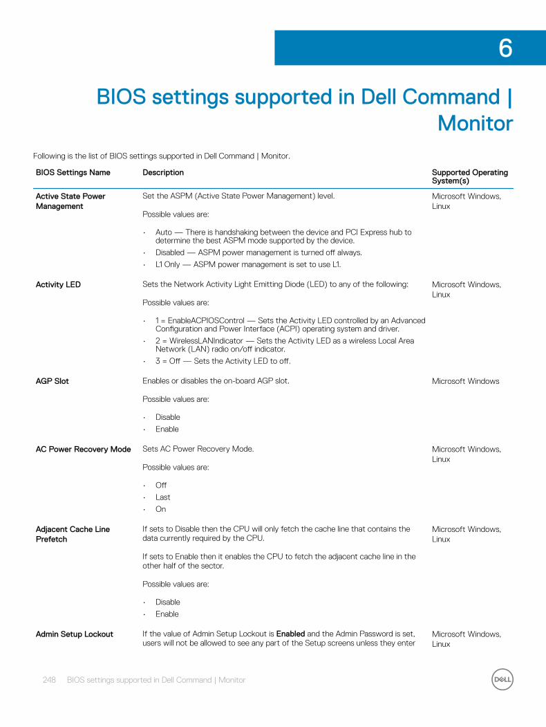
BIOS settings supported in Dell Command | Monitor
Following is the list of BIOS settings supported in Dell Command | Monitor.
BIOS Settings Name Description Supported Operating System(s)
Active State Power Management
Set the ASPM (Active State Power Management) level.
Possible values are:
• Auto — There is handshaking between the device and PCI Express hub to determine the best ASPM mode supported by the device.
• Disabled — ASPM power management is turned off always.
• L1 Only — ASPM power management is set to use L1.
Microsoft Windows, Linux
Activity LED Sets the Network Activity Light Emitting Diode (LED) to any of the following:
Possible values are:
• 1 = EnableACPIOSControl — Sets the Activity LED controlled by an Advanced Configuration and Power Interface (ACPI) operating system and driver.
• 2 = WirelessLANIndicator — Sets the Activity LED as a wireless Local Area Network (LAN) radio on/off indicator.
• 3 = Off — Sets the Activity LED to off.
Microsoft Windows, Linux
AGP Slot Enables or disables the on-board AGP slot.
Possible values are:
• Disable
• Enable
Microsoft Windows
AC Power Recovery Mode Sets AC Power Recovery Mode.
Possible values are:
• Off
• Last
• On
Microsoft Windows, Linux
Adjacent Cache Line Prefetch
If sets to Disable then the CPU will only fetch the cache line that contains the data currently required by the CPU.
If sets to Enable then it enables the CPU to fetch the adjacent cache line in the other half of the sector.
Possible values are:
• Disable
• Enable
Microsoft Windows, Linux
Admin Setup Lockout If the value of Admin Setup Lockout is Enabled and the Admin Password is set, users will not be allowed to see any part of the Setup screens unless they enter
Microsoft Windows, Linux
6
248 BIOS settings supported in Dell Command | Monitor

BIOS Settings Name Description Supported Operating System(s)
the correct Admin Password. If the Admin password is NOT set and Admin Setup Lockout is Enabled, users will be able to access Setup normally.
If the value of Admin Setup Lockout is Disabled and the Admin Password is or is not set, users will be allowed to enter Setup normally. However, many fields may still be inaccessible, depending on how other Setup security settings are configured.
Possible values are:
• Disable
• Enable
Adv Battery Charge Cfg Configures the days settings based on BeginningOfDay and workperiod. Advanced Battery charge mode uses standard charging algorithm and other methods during working hours to maximize battery health. During working hours, express charge is used to charge the batteries faster. You can configure the days and the work period during which the battery has to be charged. To enable advanced battery charging, provide the day, and set the following:
Possible values are:
• BeginningOfDay — To configure the AdvanceBatteryCharge start time in 24 hours format. The value of hour must be in the range 0–23 and minute must be 0, 15, 30, or 45.
• Workperiod — To configure the duration of charging.
Microsoft Windows, Linux
Advanced Battery Charging Mode
Configures all the batteries in the systems with Advance Battery Charging Mode to maximize the battery health.
Possible values are:
• 1 — Disable
• 2 — Enable
NOTE: If Advanced Battery Charging Mode is disabled, Dell Command | Monitor shows the instances for Adv Battery Charge Cfg with all ‘0’ values. User cannot set the values in Adv Battery Charge Cfg. When the Advanced Battery Charging Mode is enabled, instances for Adv Battery Charge Cfg reports the data retrieved from BIOS.
Microsoft Windows, Linux
Adv Battery Charge Cfg Sun
Configures the Advanced Battery charging configuration for Sunday.
Possible values are:
• 0 — 23 — Beginning of day Hour
• 0 — 59 — Beginning of day Minute
• 0 — 23 — Work Period Hour
• 0 — 59 — Work Period Minute
BIOS setting name for Set operation:
• Adv Battery Charge Cfg Sun BodHour
• Adv Battery Charge Cfg Sun BodMin
• Adv Battery Charge Cfg Sun WpHour
• Adv Battery Charge Cfg Sun WpMin
NOTE: The values defined for Minute field are 0, 15 ,30 and 45. In case you set any other value, the value is round to the lower defined value.
Microsoft Windows
Adv Battery Charge Cfg Mon
Configures the Advanced Battery charging configuration for Monday. Microsoft Windows
BIOS settings supported in Dell Command | Monitor 249
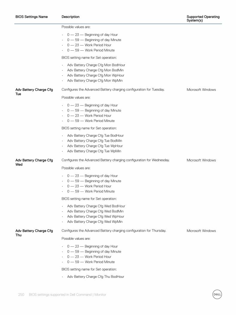
BIOS Settings Name Description Supported Operating System(s)
Possible values are:
• 0 — 23 — Beginning of day Hour
• 0 — 59 — Beginning of day Minute
• 0 — 23 — Work Period Hour
• 0 — 59 — Work Period Minute
BIOS setting name for Set operation:
• Adv Battery Charge Cfg Mon BodHour
• Adv Battery Charge Cfg Mon BodMin
• Adv Battery Charge Cfg Mon WpHour
• Adv Battery Charge Cfg Mon WpMin
Adv Battery Charge Cfg Tue
Configures the Advanced Battery charging configuration for Tuesday.
Possible values are:
• 0 — 23 — Beginning of day Hour
• 0 — 59 — Beginning of day Minute
• 0 — 23 — Work Period Hour
• 0 — 59 — Work Period Minute
BIOS setting name for Set operation:
• Adv Battery Charge Cfg Tue BodHour
• Adv Battery Charge Cfg Tue BodMin
• Adv Battery Charge Cfg Tue WpHour
• Adv Battery Charge Cfg Tue WpMin
Microsoft Windows
Adv Battery Charge Cfg Wed
Configures the Advanced Battery charging configuration for Wednesday.
Possible values are:
• 0 — 23 — Beginning of day Hour
• 0 — 59 — Beginning of day Minute
• 0 — 23 — Work Period Hour
• 0 — 59 — Work Period Minute
BIOS setting name for Set operation:
• Adv Battery Charge Cfg Wed BodHour
• Adv Battery Charge Cfg Wed BodMin
• Adv Battery Charge Cfg Wed WpHour
• Adv Battery Charge Cfg Wed WpMin
Microsoft Windows
Adv Battery Charge Cfg Thu
Configures the Advanced Battery charging configuration for Thursday.
Possible values are:
• 0 — 23 — Beginning of day Hour
• 0 — 59 — Beginning of day Minute
• 0 — 23 — Work Period Hour
• 0 — 59 — Work Period Minute
BIOS setting name for Set operation:
• Adv Battery Charge Cfg Thu BodHour
Microsoft Windows
250 BIOS settings supported in Dell Command | Monitor
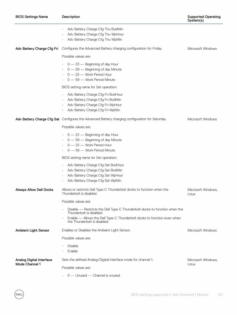
BIOS Settings Name Description Supported Operating System(s)
• Adv Battery Charge Cfg Thu BodMin
• Adv Battery Charge Cfg Thu WpHour
• Adv Battery Charge Cfg Thu WpMin
Adv Battery Charge Cfg Fri Configures the Advanced Battery charging configuration for Friday.
Possible values are:
• 0 — 23 — Beginning of day Hour
• 0 — 59 — Beginning of day Minute
• 0 — 23 — Work Period Hour
• 0 — 59 — Work Period Minute
BIOS setting name for Set operation:
• Adv Battery Charge Cfg Fri BodHour
• Adv Battery Charge Cfg Fri BodMin
• Adv Battery Charge Cfg Fri WpHour
• Adv Battery Charge Cfg Fri WpMin
Microsoft Windows
Adv Battery Charge Cfg Sat Configures the Advanced Battery charging configuration for Saturday.
Possible values are:
• 0 — 23 — Beginning of day Hour
• 0 — 59 — Beginning of day Minute
• 0 — 23 — Work Period Hour
• 0 — 59 — Work Period Minute
BIOS setting name for Set operation:
• Adv Battery Charge Cfg Sat BodHour
• Adv Battery Charge Cfg Sat BodMin
• Adv Battery Charge Cfg Sat WpHour
• Adv Battery Charge Cfg Sat WpMin
Microsoft Windows
Always Allow Dell Docks Allows or restricts Dell Type-C Thunderbolt docks to function when the Thunderbolt is disabled.
Possible values are:
• Disable — Restricts the Dell Type-C Thunderbolt docks to function when the Thunderbolt is disabled.
• Enable — Allows the Dell Type-C Thunderbolt docks to function even when the Thunderbolt is disabled.
Microsoft Windows, Linux
Ambient Light Sensor Enables or Disables the Ambient Light Sensor.
Possible values are:
• Disable
• Enable
Microsoft Windows
Analog Digital Interface Mode Channel 1
Sets the defined Analog/Digital Interface mode for channel 1.
Possible values are:
• 0 — Unused — Channel is unused.
Microsoft Windows, Linux
BIOS settings supported in Dell Command | Monitor 251
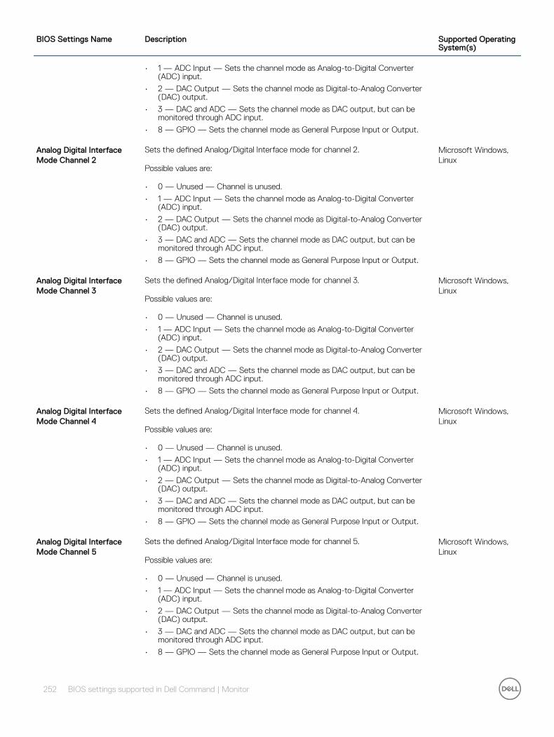
BIOS Settings Name Description Supported Operating System(s)
• 1 — ADC Input — Sets the channel mode as Analog-to-Digital Converter (ADC) input.
• 2 — DAC Output — Sets the channel mode as Digital-to-Analog Converter (DAC) output.
• 3 — DAC and ADC — Sets the channel mode as DAC output, but can be monitored through ADC input.
• 8 — GPIO — Sets the channel mode as General Purpose Input or Output.
Analog Digital Interface Mode Channel 2
Sets the defined Analog/Digital Interface mode for channel 2.
Possible values are:
• 0 — Unused — Channel is unused.
• 1 — ADC Input — Sets the channel mode as Analog-to-Digital Converter (ADC) input.
• 2 — DAC Output — Sets the channel mode as Digital-to-Analog Converter (DAC) output.
• 3 — DAC and ADC — Sets the channel mode as DAC output, but can be monitored through ADC input.
• 8 — GPIO — Sets the channel mode as General Purpose Input or Output.
Microsoft Windows, Linux
Analog Digital Interface Mode Channel 3
Sets the defined Analog/Digital Interface mode for channel 3.
Possible values are:
• 0 — Unused — Channel is unused.
• 1 — ADC Input — Sets the channel mode as Analog-to-Digital Converter (ADC) input.
• 2 — DAC Output — Sets the channel mode as Digital-to-Analog Converter (DAC) output.
• 3 — DAC and ADC — Sets the channel mode as DAC output, but can be monitored through ADC input.
• 8 — GPIO — Sets the channel mode as General Purpose Input or Output.
Microsoft Windows, Linux
Analog Digital Interface Mode Channel 4
Sets the defined Analog/Digital Interface mode for channel 4.
Possible values are:
• 0 — Unused — Channel is unused.
• 1 — ADC Input — Sets the channel mode as Analog-to-Digital Converter (ADC) input.
• 2 — DAC Output — Sets the channel mode as Digital-to-Analog Converter (DAC) output.
• 3 — DAC and ADC — Sets the channel mode as DAC output, but can be monitored through ADC input.
• 8 — GPIO — Sets the channel mode as General Purpose Input or Output.
Microsoft Windows, Linux
Analog Digital Interface Mode Channel 5
Sets the defined Analog/Digital Interface mode for channel 5.
Possible values are:
• 0 — Unused — Channel is unused.
• 1 — ADC Input — Sets the channel mode as Analog-to-Digital Converter (ADC) input.
• 2 — DAC Output — Sets the channel mode as Digital-to-Analog Converter (DAC) output.
• 3 — DAC and ADC — Sets the channel mode as DAC output, but can be monitored through ADC input.
• 8 — GPIO — Sets the channel mode as General Purpose Input or Output.
Microsoft Windows, Linux
252 BIOS settings supported in Dell Command | Monitor
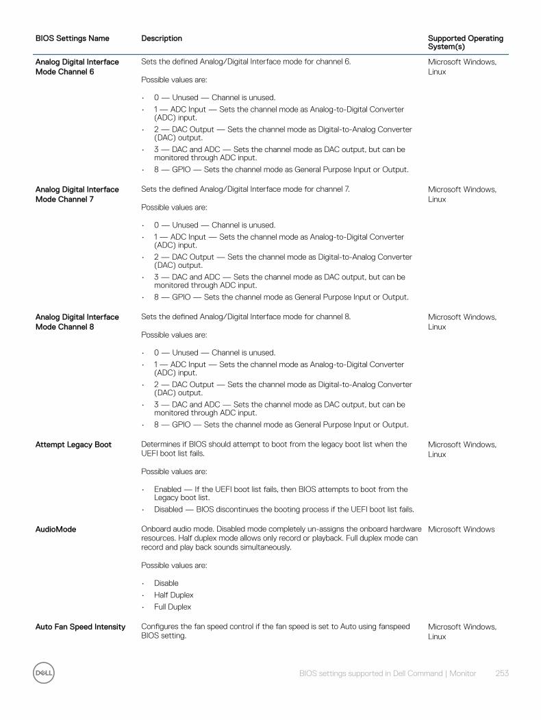
BIOS Settings Name Description Supported Operating System(s)
Analog Digital Interface Mode Channel 6
Sets the defined Analog/Digital Interface mode for channel 6.
Possible values are:
• 0 — Unused — Channel is unused.
• 1 — ADC Input — Sets the channel mode as Analog-to-Digital Converter (ADC) input.
• 2 — DAC Output — Sets the channel mode as Digital-to-Analog Converter (DAC) output.
• 3 — DAC and ADC — Sets the channel mode as DAC output, but can be monitored through ADC input.
• 8 — GPIO — Sets the channel mode as General Purpose Input or Output.
Microsoft Windows, Linux
Analog Digital Interface Mode Channel 7
Sets the defined Analog/Digital Interface mode for channel 7.
Possible values are:
• 0 — Unused — Channel is unused.
• 1 — ADC Input — Sets the channel mode as Analog-to-Digital Converter (ADC) input.
• 2 — DAC Output — Sets the channel mode as Digital-to-Analog Converter (DAC) output.
• 3 — DAC and ADC — Sets the channel mode as DAC output, but can be monitored through ADC input.
• 8 — GPIO — Sets the channel mode as General Purpose Input or Output.
Microsoft Windows, Linux
Analog Digital Interface Mode Channel 8
Sets the defined Analog/Digital Interface mode for channel 8.
Possible values are:
• 0 — Unused — Channel is unused.
• 1 — ADC Input — Sets the channel mode as Analog-to-Digital Converter (ADC) input.
• 2 — DAC Output — Sets the channel mode as Digital-to-Analog Converter (DAC) output.
• 3 — DAC and ADC — Sets the channel mode as DAC output, but can be monitored through ADC input.
• 8 — GPIO — Sets the channel mode as General Purpose Input or Output.
Microsoft Windows, Linux
Attempt Legacy Boot Determines if BIOS should attempt to boot from the legacy boot list when the UEFI boot list fails.
Possible values are:
• Enabled — If the UEFI boot list fails, then BIOS attempts to boot from the Legacy boot list.
• Disabled — BIOS discontinues the booting process if the UEFI boot list fails.
Microsoft Windows, Linux
AudioMode Onboard audio mode. Disabled mode completely un-assigns the onboard hardware resources. Half duplex mode allows only record or playback. Full duplex mode can record and play back sounds simultaneously.
Possible values are:
• Disable
• Half Duplex
• Full Duplex
Microsoft Windows
Auto Fan Speed Intensity Configures the fan speed control if the fan speed is set to Auto using fanspeed BIOS setting.
Microsoft Windows, Linux
BIOS settings supported in Dell Command | Monitor 253

BIOS Settings Name Description Supported Operating System(s)
Possible values are: 0 to 100
• 0 — sets the fanspeed to the optimal speed level, and higher percentage provides enhanced cooling.
Auto On This property defines the auto-on configuration: disabled, everyday or weekdays (Monday — Friday).
Possible values are:
• Disable
• Everyday
• Weekdays
• Select days
Microsoft Windows, Linux
Auto On Hour Defines the hour when to turn on the system (0–23). Microsoft Windows, Linux
Auto On Minute Defines the minutes when to turn on the system (0–59). Microsoft Windows, Linux
Auto on Sunday Defines that the system must be automatically turned on Sundays. Microsoft Windows, Linux
Auto on Monday Defines that the system must be automatically turned on Mondays. Microsoft Windows, Linux
Auto on Tuesday Defines that the system must be automatically turned on Tuesdays. Microsoft Windows, Linux
Auto on Wednesday Defines that the system must be automatically turned on Wednesdays. Microsoft Windows, Linux
Auto on Thursday Defines that the system must be automatically turned on Thursdays. Microsoft Windows, Linux
Auto on Friday Defines that the system must be automatically turned on Fridays. Microsoft Windows, Linux
Auto on Saturday Defines that the system must be automatically turned on Saturdays. Microsoft Windows, Linux
Auto OS Recovery Threshold
Sets the threshold value for auto OS recovery. Controls the automatic boot flow for SupportAssist System Resolution console and for Dell OS Recovery Tool. The system boots to the SupportAssist System Resolution console and for Dell OS Recovery Tool if,
• the primary operating system fails to boot consecutively
• the count of boot failure is greater than or equal to the value of the Auto OS Recovery threshold setup option
• the SupportAssist OS Recovery option is enabled
Possible values are: 0 to 3
NOTE: If the Auto OS Recovery threshold is set to 0, then all automatic boot flow for SupportAssist System Resolution console and for Dell OS Recovery Tool is disabled.
Microsoft Windows, Linux
Auto Switch Enable, Disable
Possible values are: 1,2
Microsoft Windows, Linux
Auto Wake Period Defines the time in minutes after which the system should automatically wake up from Standby, Hibernate, or Switched off mode.
Microsoft Windows, Linux
254 BIOS settings supported in Dell Command | Monitor
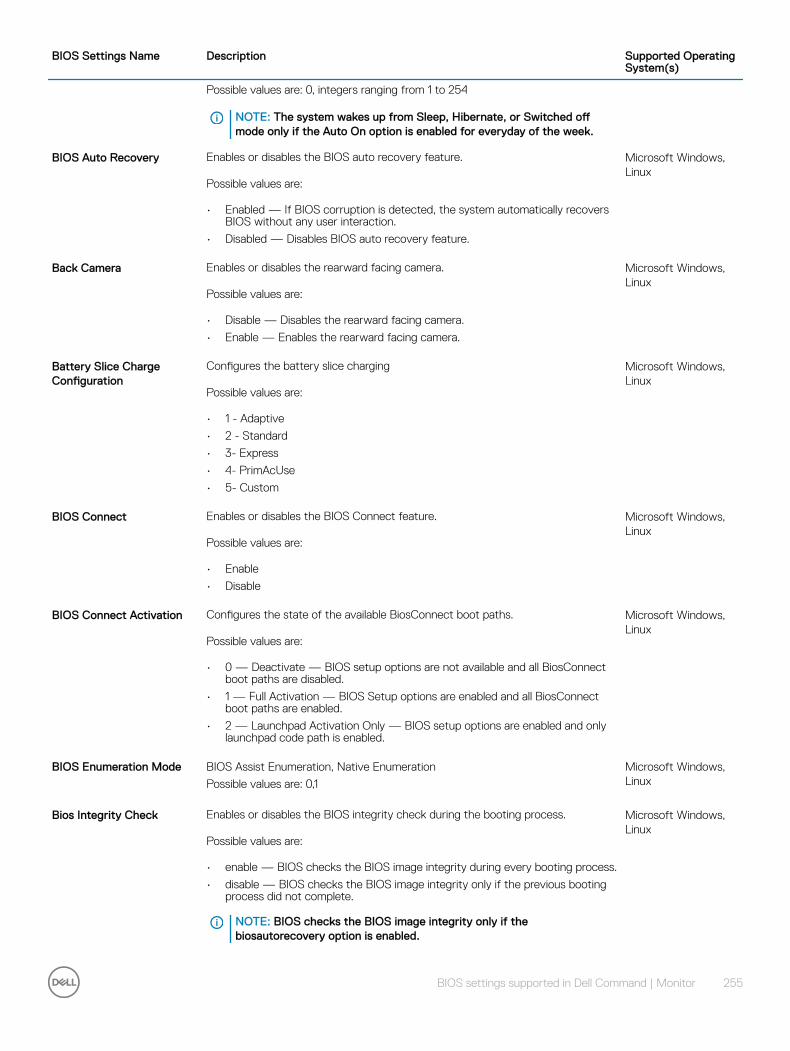
BIOS Settings Name Description Supported Operating System(s)
Possible values are: 0, integers ranging from 1 to 254
NOTE: The system wakes up from Sleep, Hibernate, or Switched off mode only if the Auto On option is enabled for everyday of the week.
BIOS Auto Recovery Enables or disables the BIOS auto recovery feature.
Possible values are:
• Enabled — If BIOS corruption is detected, the system automatically recovers BIOS without any user interaction.
• Disabled — Disables BIOS auto recovery feature.
Microsoft Windows, Linux
Back Camera Enables or disables the rearward facing camera.
Possible values are:
• Disable — Disables the rearward facing camera.
• Enable — Enables the rearward facing camera.
Microsoft Windows, Linux
Battery Slice Charge Configuration
Configures the battery slice charging
Possible values are:
• 1 - Adaptive
• 2 - Standard
• 3- Express
• 4- PrimAcUse
• 5- Custom
Microsoft Windows, Linux
BIOS Connect Enables or disables the BIOS Connect feature.
Possible values are:
• Enable
• Disable
Microsoft Windows, Linux
BIOS Connect Activation Configures the state of the available BiosConnect boot paths.
Possible values are:
• 0 — Deactivate — BIOS setup options are not available and all BiosConnect boot paths are disabled.
• 1 — Full Activation — BIOS Setup options are enabled and all BiosConnect boot paths are enabled.
• 2 — Launchpad Activation Only — BIOS setup options are enabled and only launchpad code path is enabled.
Microsoft Windows, Linux
BIOS Enumeration Mode BIOS Assist Enumeration, Native Enumeration
Possible values are: 0,1
Microsoft Windows, Linux
Bios Integrity Check Enables or disables the BIOS integrity check during the booting process.
Possible values are:
• enable — BIOS checks the BIOS image integrity during every booting process.
• disable — BIOS checks the BIOS image integrity only if the previous booting process did not complete.
NOTE: BIOS checks the BIOS image integrity only if the biosautorecovery option is enabled.
Microsoft Windows, Linux
BIOS settings supported in Dell Command | Monitor 255

BIOS Settings Name Description Supported Operating System(s)
BIOS Recovery Enables or disables the system BIOS Recovery option. This feature saves a recovery image to a primary hard disk drive storage, or to an external USB, and uses this recovery image to recover BIOS image when system BIOS fails.
Possible values are:
• Enable — BIOS stores the recovery image on primary hard disk drive storage. So BIOS recovery image is available both from primary hard disk drive permanent storage and via an external USB.
• Disable — BIOS does not store the recovery image on primary hard disk drive storage. So BIOS recovery image is available only via an external USB.
Microsoft Windows, Linux
Bitsmart Enables or disable the Bitsmart.
Possible values are:
• Disable
• Enable
Microsoft Windows
Bluetooth Devices Enable or disable Bluetooth Devices
Possible values are:
• Disable
• Enable
Microsoft Windows, Linux
BlinkPSULED1 Provides the alert for the PSU 1. The Power Supply Unit(PSU) 1 LED starts to blink when it is enabled.
Possible value:
• Enable
Microsoft Windows
BlinkPSULED2 Provides the alert for the PSU 2. The Power Supply Unit(PSU) 2 LED starts to blink when it is enabled.
Possible value:
• Enable
Microsoft Windows
BlockS3 Enables or disables the Block S3 sleep state. If this option is Disabled, the system BIOS supports OSPM/ACPI S3 (suspend to RAM) operation. This moves the system authentication into the operating system and bypasses any Preboot Authentication on resume.
If this option is Enabled, the system BIOS blocks all OSPM/ACPI S3 (suspend to RAM) requests and enforces Preboot Authentication on all non-S3 resumes.
Possible values are:
• Disable
• Enable
Microsoft Windows, Linux
Boot Mode Determines the system’s boot mode. Enables booting to Unified Extensible Firmware Interface (UEFI) capable operating systems. This ensures compatibility with operating systems that do not support UEFI.
Possible values are:
• UEFI — Enables booting to Unified Extensible Firmware Interface (UEFI) capable operating systems.
• BIOS — Ensures compatibility with operating systems that do not support UEFI.
Microsoft Windows, Linux
256 BIOS settings supported in Dell Command | Monitor

BIOS Settings Name Description Supported Operating System(s)
NOTE: Legacy boot mode is not allowed when secure boot is enabled or legacy option ROM is disabled.
Boot-time Video Sets the Primary Video source.
Possible values are:
• On board
• Add-in
Microsoft Windows, Linux
Boot Speed Sets CPU speed to default or compatible (low speed). This feature is implementation-dependent. There is no set speed for Compatible, only that it is slower than default. Some platforms implement this by turning off cache and others by STPCLK throttling.
Possible values are:
• Default
• Compatible
Microsoft Windows
Broadcom ASF Sets the ASF (Alert Standard Format) mode.
Possible values are:
• Disable
• Enable
• Alert only
• Dash and ASF
Microsoft Windows
Broadcom TruManage Sets the Broadcom TruManage.
Possible values are: 1,2
• Enable
• Disable
Microsoft Windows
Bus Ratio Sets Bus Ratio.
Possible values are:
• Max
• 6.0
• 7.0
• 7.5
• 8.0
• 8.5
• 9.0
• 9.5
Microsoft Windows
Camera Enables or disables the camera.
Possible values are:
• Disable
• Enable
Microsoft Windows, Linux
CAN Bus Enables or disables the Controller Area Network (CAN) Bus. Microsoft Windows, Linux
BIOS settings supported in Dell Command | Monitor 257

BIOS Settings Name Description Supported Operating System(s)
Possible values are:
• Disable
• Enable
Cellular Radio Enables or Disables the cellular radio, that is, the WWAN module.
Possible values are:
• Disable
• Enable
Microsoft Windows, Linux
Charger Defines the charger details.
Possible values are:
• Disable
• Enable
Microsoft Windows
Chassis Intrusion Enables the system to detect and report the Chassis Intrusion events to the system display on boot-up.
Possible values are:
• Disable
• Enable
• Silent
Microsoft Windows, Linux
Chassis Intrusion Status This property shows the status of the system with regards to Chassis Intrusion (Detected or Not Detected). A value of Unknown indicates one of two things: either Chassis Intrusion is not supported by this system, or Chassis Intrusion event reporting has been disabled by the user. If the value is Detected, the user may set it to Not Detected to enable the system to receive the next event and to stop generating events for now.
Possible values are:
• Tripped
• Door open
• Door closed
• Trip reset
Microsoft Windows, Linux
Clear BIOS Log Prevents or allows the BIOS event log to be cleared on the next boot.
Possible values are:
• Disable — Does not clear the BIOS event log on the next boot.
• Enable — Clears the BIOS event log on the next boot.
Microsoft Windows, Linux
Clear Power Log Prevents or allows the Power log to be cleared on the next boot.
Possible values are:
• Disable — Does not clear the Power log on the next boot.
• Enable — Clears the Power log on the next boot.
Microsoft Windows, Linux
Clear System Event Log Prevents or causes the system event log to be cleared on the next boot.
Possible values are:
• Disable
Microsoft Windows, Linux
258 BIOS settings supported in Dell Command | Monitor
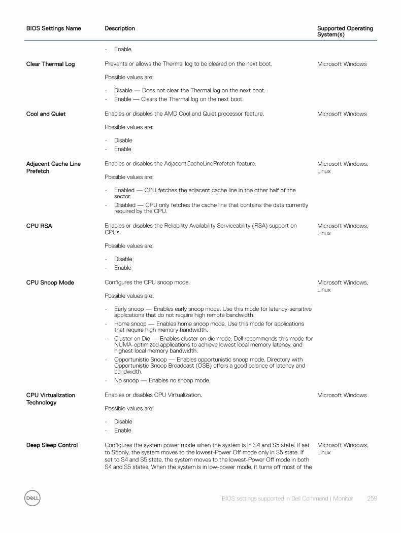
BIOS Settings Name Description Supported Operating System(s)
• Enable
Clear Thermal Log Prevents or allows the Thermal log to be cleared on the next boot.
Possible values are:
• Disable — Does not clear the Thermal log on the next boot.
• Enable — Clears the Thermal log on the next boot.
Microsoft Windows
Cool and Quiet Enables or disables the AMD Cool and Quiet processor feature.
Possible values are:
• Disable
• Enable
Microsoft Windows
Adjacent Cache Line Prefetch
Enables or disables the AdjacentCacheLinePrefetch feature.
Possible values are:
• Enabled — CPU fetches the adjacent cache line in the other half of the sector.
• Disabled — CPU only fetches the cache line that contains the data currently required by the CPU.
Microsoft Windows, Linux
CPU RSA Enables or disables the Reliability Availability Serviceability (RSA) support on CPUs.
Possible values are:
• Disable
• Enable
Microsoft Windows, Linux
CPU Snoop Mode Configures the CPU snoop mode.
Possible values are:
• Early snoop — Enables early snoop mode. Use this mode for latency-sensitive applications that do not require high remote bandwidth.
• Home snoop — Enables home snoop mode. Use this mode for applications that require high memory bandwidth.
• Cluster on Die — Enables cluster on die mode. Dell recommends this mode for NUMA-optimized applications to achieve lowest local memory latency, and highest local memory bandwidth.
• Opportunistic Snoop — Enables opportunistic snoop mode. Directory with Opportunistic Snoop Broadcast (OSB) offers a good balance of latency and bandwidth.
• No snoop — Enables no snoop mode.
Microsoft Windows, Linux
CPU Virtualization Technology
Enables or disables CPU Virtualization.
Possible values are:
• Disable
• Enable
Microsoft Windows
Deep Sleep Control Configures the system power mode when the system is in S4 and S5 state. If set to S5only, the system moves to the lowest-Power Off mode only in S5 state. If set to S4 and S5 state, the system moves to the lowest-Power Off mode in both S4 and S5 states. When the system is in low-power mode, it turns off most of the
Microsoft Windows, Linux
BIOS settings supported in Dell Command | Monitor 259

BIOS Settings Name Description Supported Operating System(s)
power-consuming circuitry, to meet the 1 W power limit. It disables PME, USB power, etc.
Possible values are:
• S5 only
• S4 and S5
• Disable
Dell Reliable Memory Technology
Configures the system to detect and correct the software errors in a block of RAM. When enabled, the system detects and corrects the software errors.
Possible values are:
• Disable
• Enable
Microsoft Windows, Linux
Dell Wyse P25 Bios Access Turns on or off the access to the BIOS setup through Dell Wyse P25 PCoIP client.
Possible values are:
• On
• Off
Microsoft Windows
dGPU External Display Enables or disables discrete Graphics Procession (GPU) Unit external display.
Possible values are:
• Disable
• Enable
Microsoft Windows, Linux
Diskette This property defines whether the built-in Floppy controller is enabled, auto or read-only.
Possible values are:
• Disable
• Auto
• Read Only
• USB Internal
Microsoft Windows
Dock Display Port 1 Video Source
Configures the Dock Display Port 1 Video Source. This option enables or disables switchable graphics technologies.
Possible values are:
• Integrated
• External
Microsoft Windows, Linux
Dock Support On Battery Enabling this option allows you to use the docking station, when AC power is absent, but only when the battery is preceding a certain charge percentage. The percentage may change per battery and per platform. For example, the dock may only be powered when the battery is at 60 percent charge or higher, and when the battery drops below this level (without AC power) the dock loses power.
Possible values are:
• Disable
• Enable
Microsoft Windows, Linux
DRAM Prefetcher Prevents DRAM references from triggering DRAM prefetch requests./Turns on the DRAM prefetch unit in the Northbridge.
Microsoft Windows
260 BIOS settings supported in Dell Command | Monitor
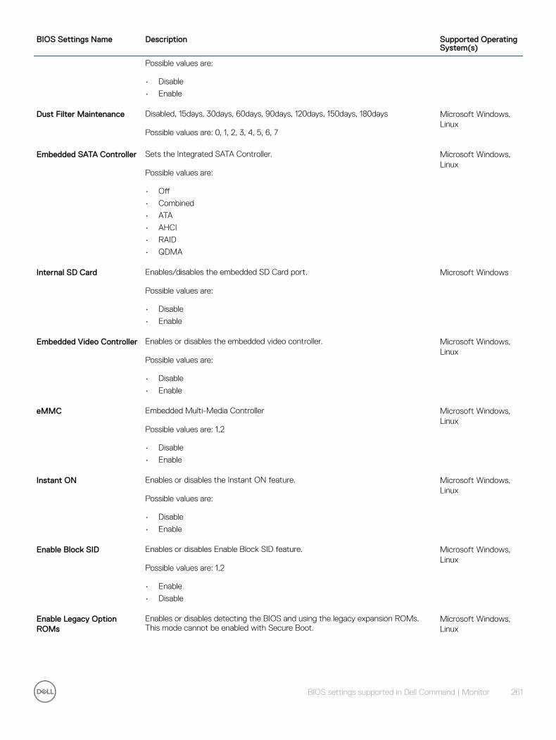
BIOS Settings Name Description Supported Operating System(s)
Possible values are:
• Disable
• Enable
Dust Filter Maintenance Disabled, 15days, 30days, 60days, 90days, 120days, 150days, 180days
Possible values are: 0, 1, 2, 3, 4, 5, 6, 7
Microsoft Windows, Linux
Embedded SATA Controller Sets the Integrated SATA Controller.
Possible values are:
• Off
• Combined
• ATA
• AHCI
• RAID
• QDMA
Microsoft Windows, Linux
Internal SD Card Enables/disables the embedded SD Card port.
Possible values are:
• Disable
• Enable
Microsoft Windows
Embedded Video Controller Enables or disables the embedded video controller.
Possible values are:
• Disable
• Enable
Microsoft Windows, Linux
eMMC Embedded Multi-Media Controller
Possible values are: 1,2
• Disable
• Enable
Microsoft Windows, Linux
Instant ON Enables or disables the Instant ON feature.
Possible values are:
• Disable
• Enable
Microsoft Windows, Linux
Enable Block SID Enables or disables Enable Block SID feature.
Possible values are: 1,2
• Enable
• Disable
Microsoft Windows, Linux
Enable Legacy Option ROMs
Enables or disables detecting the BIOS and using the legacy expansion ROMs. This mode cannot be enabled with Secure Boot.
Microsoft Windows, Linux
BIOS settings supported in Dell Command | Monitor 261

BIOS Settings Name Description Supported Operating System(s)
Possible values are:
• Enable
• Disable
Enable Tablet Button LED Sign of Life
Enables or disables Tablet Button LED Sign of Life.
Possible values are: 1,2
• Enable
• Disable
Enclave Memory Size Displays the Intel(R) Software Guard Extensions(TM) (SGX) Enclave Reverse Memory Size.
Possible values are:
• 0 = 32MB
• 1 = 64MB
• 2 = 128MB
NOTE: Enclave Memory Size option can be set from the BIOS setup screen only.
Microsoft Windows, Linux
Energy Star Logo Displays or hides the Energy Star logo during POST.
Possible values are:
• Disable
• Enable
Microsoft Windows, Linux
e-SATA Ports Enable/disable e-SATA Ports
Possible values are:
• Disable
• Enable
Microsoft Windows, Linux
Express Card This setting will enable the express card port, which allows the user to insert an express card into the slot and it will be configured.
Possible values are:
• Disable
• Enable
Microsoft Windows, Linux
Express Charge Define the express charging.
Possible values are:
• Disable
• Enable
• Enable once
Microsoft Windows
Extend Post Time Delays the time of action taken by the system after pressing function keys such as F2,F12, etc. during post time.
Possible values are:
• 0 — Does not delay the time of action.
• 5 — Delays the time of action by 5 seconds.
Microsoft Windows, Linux
262 BIOS settings supported in Dell Command | Monitor

BIOS Settings Name Description Supported Operating System(s)
• 10 — Delays the time of action by 10 seconds.
External Hotkey Sets the External Hotkey to Scroll Lock or Disabled.
Possible values are:
• Disable
• Scroll lock
Microsoft Windows, Linux
External USB Ports Enable/disable external USB ports.
Possible values are:
• Disable
• Enable
Microsoft Windows, Linux
External WLAN Activity LED
Enables or disables the external (lid-mounted) WLAN indicator LED.
Possible values are:
• Disable — LED does not display the state of the WLAN source activity.
• Enable — LED displays the state of the WLAN source activity.
Microsoft Windows, Linux
F12 POST Display Enables or disables the F12 key at POST.
Possible values are:
• Disable
• Enable
Microsoft Windows, Linux
F2 POST Display Enables or disables the F2 key at POST.
Possible values are:
• Disable
• Enable
Microsoft Windows
Fan Control Override Controls the speed of the fan. When enabled the fan runs at full speed. When disabled, the fan controller uses the system environmental data to set the fan at its optimal speed.
Possible values are:
• Disable
• Enable
Microsoft Windows, Linux
Fan Speed Sets the system fan speed.
Possible values are:
• Auto
• High
• Medium High
• Medium Low
• Low
Microsoft Windows, Linux
Fan Speed Auto Level on Psu Zone
Sets the system to Fan Speed Auto Level on Psu Zone. Microsoft Windows, Linux
BIOS settings supported in Dell Command | Monitor 263

BIOS Settings Name Description Supported Operating System(s)
Possible values are: 0 – 100
• Minimum Value
• Minimum Value
Fan Speed Auto Level on Cpu Zone
Sets the system to Fan Speed Auto Level on Cpu Zone.
Possible values are: 0 – 100
• Minimum Value
• Minimum Value
Microsoft Windows, Linux
Dell Reliable Memory Technology
Configures the system to detect and correct the software errors in a block of RAM. When enabled, the system detects and corrects the software errors.
Possible values are:
• Disable
• Enable
Microsoft Windows
Fault Tolerant Memory Log Clear
Enables or disables the Fault Tolerant Memory Log Clear option.
Possible values are:
• Enabled — System clears fault tolerant memory log during the next boot.
• Disabled — Fault Tolerant Memory Log Clear option will be disabled, and no action will be taken during the next boot.
NOTE: Fault Tolerant Memory Log Clear option will be reset to disabled state after log gets cleared.
Microsoft Windows, Linux
Fn Lock Controls the behavior of the dual-function keys (<F1> — <F12>), when <Fn> key is pressed.
Possible values are:
• Disable — If disabled, holding the <Fn> key enables the secondary functions associated with the particular key.
• Enable — If enabled, holding the <Fn> key enables the labeled functions of the keys (<F1> — <F12>).
Microsoft Windows, Linux
Fn Lock Mode Controls the behavior of the dual-function keys (<F1> — <F12>), when <Fn> key is pressed and when it is not.
Possible values are:
• Disable — Holding <Fn> key enables the secondary functions associated with the particular key
• Enable — Without holding <Fn> key, the dual-function keys behave as labeled.
Microsoft Windows, Linux
Force PXE on Next Boot Enables or disables the Force PXE on next boot in BIOS.
Possible values are:
• Disable
• Enable
Microsoft Windows, Linux
Front Panel USB Ports Enables or disables the USB ports on the front of the chassis.
Possible values are:
• Disable
Microsoft Windows, Linux
264 BIOS settings supported in Dell Command | Monitor

BIOS Settings Name Description Supported Operating System(s)
• Enable
Full Screen Logo Enables or disables the full screen logo.
Possible values are:
• Disable
• Enable
Microsoft Windows
FX100 BIOS Access Allows or blocks the remote user to access BIOS Setup via FX100 Portal.
Possible values are:
• On
• Off
Microsoft Windows
General Purpose Encryption
Enables or disables the general purpose encryption (GPE) on the system.
Possible values are:
• Enable
• Disable
Microsoft Windows
GPS on WWAN Radio Enables or disables GPS WWAN Radio.
Possible values are:
• Enable
• Disable
Microsoft Windows, Linux
GPS Radio Enables or disables the internal GPS radio.
Possible values are:
• Enable
• Disable
Microsoft Windows, Linux
Hard Disk Acoustic Mode Sets the Hard Disk Acoustic Mode.
Possible values are:
• Bypass
• Quiet
• Suggested
• Performance
Microsoft Windows
Hard-Disk Failover Specifies which devices in the Hard-Disk Drive Sequence menu are attempted in the boot sequence. When set to OFF, only the first device in the list is attempted. When set to ON, all devices are attempted in order, as listed in the Hard-Disk Drive Sequence.
Possible values are:
• Disable
• Enable
Microsoft Windows
Hardware Prefetcher Enables or disables the CPU’s HW prefetcher.
Possible values are:
• Disable
Microsoft Windows, Linux
BIOS settings supported in Dell Command | Monitor 265

BIOS Settings Name Description Supported Operating System(s)
• Enable
Hard Drive Free Fall Protection
Enables or disables hard drive free fall protection.
Possible values are:
• Disable
• Enable
Microsoft Windows, Linux
Hardware Prefetch Training on Software Prefetch
Prevents hardware prefetcher from considering software prefetches when detecting strides for prefetch requests./Hardware prefetcher considers software prefetches when detecting strides for prefetch requests.
Possible values are:
• Disable
• Enable
Microsoft Windows, Linux
HDD Protection If setting On, the HDD Protection OPROM will be loaded. If setting Off, the HDD Protection OPROM will be not loaded.
Possible values are:
• Off
• On
Microsoft Windows, Linux
HDD0 Fan Enable Enables or disables checking errors on the fan controller FAN_HDD0. If the fan controller detects a valid fan, it enables it automatically.
Possible values are:
• Enable
• Disable
Microsoft Windows, Linux
HDD1 Fan Enable Enables or disables checking errors on the fan controller FAN_HDD1. If the fan controller detects a valid fan, it enables it automatically.
Possible values are:
• Disable
• Enable
Microsoft Windows, Linux
HDD2 Fan Enable Enables or disables checking errors on the fan controller FAN_HDD2. If the fan controller detects a valid fan, it enables it automatically.
Possible values are:
• Disable
• Enable
Microsoft Windows, Linux
HDD3 Fan Enable Enables or disables checking errors on the fan controller FAN_HDD3. If the fan controller detects a valid fan, it enables it automatically.
Possible values are:
• Disable
• Enable
Microsoft Windows, Linux
HDD4 Fan Enable Enables or disables checking errors on the fan controller FAN_HDD4. If the fan controller detects a valid fan, it enables it automatically.
Microsoft Windows, Linux
266 BIOS settings supported in Dell Command | Monitor
BIOS Settings Name Description Supported Operating System(s)
Possible values are:
• Disable
• Enable
Hot Undocking Enables or disables warm and hot docking/undocking.
Possible values are:
• Disable
• Enable
Microsoft Windows
Hotkey to toggle WxAN Radio
Enables or disables the hotkey to toggle WxAN radio.
Possible values are:
• Disable
• Enable
Microsoft Windows, Linux
I/O Module Enables or disables I/O module
Possible values are:
• Disable
• Enable
Microsoft Windows, Linux
Intel Smart Connect Technology
Disables or enables the Intel Smart Connect technology.
Possible values are:
• Disable
• Enable
Microsoft Windows, Linux
Intel Speed Shift Technology
Disables or enables the Intel Speed Shift Technology.
Possible values are: 1,2
• Disable
• Enable
Microsoft Windows, Linux
Intel Platform Trust Technology
Displays or hides the Intel Platform Trust Technology (PTT) device from the operating system on the next reboot. When disabled, the PTT device is not displayed to the operating system and no changes can be made to the PTT device or its content.
Possible values are:
• Disable
• Enable
Microsoft Windows
Intel Rapid Start Technology
Disables or enables the Intel Rapid Start Technology (iFFS) feature within the BIOS.
Possible values are:
• Disable
• Enable
Microsoft Windows, Linux
Intel Rapid Start Technology Timer
Allows configuring the time-out value for Intel Rapid Start Technology (IRST) mode.
Microsoft Windows
BIOS settings supported in Dell Command | Monitor 267

BIOS Settings Name Description Supported Operating System(s)
Possible value is:
• 0 — 999
NOTE: The value for IRST is a nonfixed value, which may change depending on the configuration.
Intel Ready Mode Technology
Enables or disables Intel Ready Mode Technology (iRMT).
Possible values are:
• Disable
• Enable
Microsoft Windows, Linux
Integrated RAID Enables or disables the Integrated RAID Controller.
Possible values are:
• Disable
• Enable
Microsoft Windows
Integrated SAS Enables or disables the Integrated SAS Controller.
Possible values are:
• Disable
• Enable
Microsoft Windows, Linux
Integrated USB Hub Sets the Integrated USB Hub to Compatible or High Speed.
Possible values are:
• Disable
• Enable
Microsoft Windows
Internal USB Enables or disables the Internal USB.
Possible values are:
• Disable
• Enable
Microsoft Windows, Linux
Internal USB Port Enables or disables the Internal USB port.
Possible values are:
• Disable
• Enable
Microsoft Windows
Internal USB Port 1 Enables or disables the Internal USB port 1.
Possible values are:
• Disable
• Enable
Microsoft Windows
Internal USB Port 2 Enables or disables the Internal USB port 2.
Possible values are:
• Disable
• Enable
Microsoft Windows
268 BIOS settings supported in Dell Command | Monitor

BIOS Settings Name Description Supported Operating System(s)
IDE Defines whether the IDE controller is enabled or disabled.
Possible values are:
• Disable
• Auto
Microsoft Windows
Intel Rapid Start Timer Configures the timeout value (in minutes) for Intel Rapid Start Technology (IRST) mode. After the set timeout, the system enters IRST mode from the S3 system sleep mode. The acceptable values are in the range 0-999.
Possible values are:
• integers ranging from 0 to 999
Microsoft Windows
Keyboard Backlight Active Color
Displays or sets an active color for the keyboard backlight for the rugged systems.
Possible values are:
• 0— White
• 1— Red
• 2— Green
• 3— Blue
• 4 — Customcolor1
• 5— Customcolor2
Microsoft Windows, Linux
Keyboard Backlight Custom Color 1
Displays and configures the custom color 1 by specifying the Red, Green and Blue (RGB) values. The color can be selected using RGB components by mentioning it in ‘R,G,B’ format. Each color component value ranges from 0 to 255.
Possible value is:
• 0–255, 0–255, 0–255 — Red, Green, Blue
Microsoft Windows, Linux
Keyboard Backlight Custom Color 2
Displays and configures the custom color 2 by specifying the Red, Green and Blue (RGB) values. The color can be selected using RGB components by mentioning it in ‘R,G,B’ format. Each color component value ranges from 0 to 255.
Possible value is:
• 0–255, 0–255, 0–255 — Red, Green, Blue
Microsoft Windows, Linux
Keyboard Backlight Color Enable
Displays or enables the supported colors on the keyboard backlight for the rugged systems. Press Fn+C to switch among the enabled colors.
Possible values are:
• 0 — None
• 1 — White
• 2 — Red
• 3 — Green
• 4 — Blue
• 5 — Customcolor1
• 6 — Customcolor2
Microsoft Windows
BIOS settings supported in Dell Command | Monitor 269

BIOS Settings Name Description Supported Operating System(s)
NOTE:
• You can enable multiple colors at a time.
• If ‘0 — None’ is selected, keyboard backlight color switching by pressing Fn+C will not be possible. The value ‘0 — None’ cannot be combined with any other color.
Keyboard Click Enables or disables the keyboard to ‘click’ each time a key is pressed.
Possible values are:
• Disable
• Enable
Microsoft Windows, Linux
Keyboard Backlight Timeout on AC
Configures the timeout value for the keyboard backlight when an AC adapter is plugged into the system.
Possible values are:
• 5 — Keyboard backlight stays on for 5 seconds.
• 10 — Keyboard backlight stays on for 10 seconds.
• 15 — Keyboard backlight stays on for 15 seconds.
• 30 — Keyboard backlight stays on for 30 seconds.
• 65 — Keyboard backlight stays on for 1 minute.
• 69 — Keyboard backlight stays on for 5 minutes.
• 79 — Keyboard backlight stays on for 15 minutes.
• 191 — keyboard backlight always stays on.
Microsoft Windows, Linux
Keyboard Backlight Timeout on Battery
Configures the timeout value for the keyboard backlight when the system is running only on battery power.
Possible values are:
• 5 — Keyboard backlight stays on for 5 seconds.
• 10 — Keyboard backlight stays on for 10 seconds.
• 15 — Keyboard backlight stays on for 15 seconds.
• 30 — Keyboard backlight stays on for 30 seconds.
• 65 — Keyboard backlight stays on for 1 minute.
• 69 — Keyboard backlight stays on for 5 minutes.
• 79 — Keyboard backlight stays on for 15 minutes.
• 191 — keyboard backlight always stays on.
Microsoft Windows, Linux
Keyboard Backlight with AC Enables or disables the keyboard backlight when the system is running on AC power if an AC power adapter is plugged in.
Possible values are:
• Enable — Enables the keyboard backlight even after the 10 seconds of inactivity.
• Disable — Disables the timer that fades the keyboard backlight after 10 seconds of inactivity.
NOTE: If the keyboard backlight is disabled by pressing <Fn ><F10>, then the keyboard backlight stays off even if the AC power adapter is plugged in.
Microsoft Windows, Linux
Keyboard Click Enables or disables the keyboard to ‘click’ each time a key is pressed. Microsoft Windows
270 BIOS settings supported in Dell Command | Monitor

BIOS Settings Name Description Supported Operating System(s)
Possible values are:
• Disable
• Enable
Keyboard Error Reporting Enables or disables reporting of Keyboard errors by POST.
Possible values are:
• Disable
• Enable
Microsoft Windows, Linux
Keyboard Illumination Sets the Keyboard Illumination to Enable, Disable, or Auto.
Possible values are:
• Disable
• Enable
• Auto
• 25
• 50
• 75
• 100
Microsoft Windows, Linux
Keypad Changes the means of enabling the keypad.
Possible values are:
• By numlock
• BY FN key
Microsoft Windows, Linux
Latitude ON Enables or disables Latitude On.
Possible values are:
• Disable
• Enable
Microsoft Windows
Latitude ON Flash Enables or disables the ability to boot to the Latitude ON Flash module.
Possible values are:
• Disable
• Enable
Microsoft Windows, Linux
LCD Brightness On AC Sets the panel brightness in effect when the system is using AC power.
Possible values are: Integers ranging from 0 to 15
Linux
LCD Brightness On Battery Sets the panel brightness in effect when the system is running on battery power.
Possible values are: Integers ranging from 0 to 15
Linux
Lid Switch Enables or disables the lid switch functions.
Possible values are:
• Disable — Display will not be affected when lid is closed.
• Enable — OS setting determines the display behavior when lid is closed.
Microsoft Windows, Linux
BIOS settings supported in Dell Command | Monitor 271

BIOS Settings Name Description Supported Operating System(s)
Liquid Cooler 1 Enables or disables the liquid cooler 1.
Possible values are:
• Enable — Enables the liquid cooler 1.
• Disable — Disables the liquid cooler 1.
Microsoft Windows, Linux
Liquid Cooler 2 Enables or disables the liquid cooler 2.
Possible values are:
• Enable — Enables the liquid cooler 2.
• Disable — Disables the liquid cooler 2.
Microsoft Windows, Linux
Limit CPUID Value Enables or disables the Limit CPUID Value feature.
Possible values are:
• Disable
• Enable
Microsoft Windows, Linux
M2 PCIE SSD 0 Enables or disables M2 PCIE SSD 0.
Possible values are:
• Disable
• Enable
Microsoft Windows, Linux
M2 PCIE SSD 1 Enables or disables M2 PCIE SSD 1.
Possible values are:
• Disable
• Enable
Microsoft Windows, Linux
Management Driver Sets to Present: the system-management instrumentation sets this BIOS setting when it loads to instruct that BIOS that operating system level software is handling any out-of-range management condition — if a critical threshold is passed, the driver takes responsibility for shutting down the operating system and powering off the system. The instrumentation is responsible for de-registering itself via the Absent BIOS setting when it unloads. Implementation.
NOTE: To maintain compatibility with Dell Command | Monitor, a BIOS that implements this BIOS setting via an Indexed I/O access method must ensure that an AND-mask of 0xFB and an OR-value of 0x04 maintains the present status— i.e. the status is in bit 2 of the indexed I/O location.
Sets to Absent: this BIOS setting indicates to the system BIOS that any system-management monitoring is its responsibility. If an out-of-range management condition occurs in the system, the BIOS powers off the system to prevent hardware damage. Implementation Note: To maintain compatibility with Dell Command | Monitor, a BIOS that implements of this BIOS setting via an Indexed I/O access method must ensure that an AND-mask of 0xFB and an OR-value of 0x00 maintains the absent status — i.e. the status is in bit 2 of the indexed I/O location.
Possible values are:
• Present
• Absent
Microsoft Windows
272 BIOS settings supported in Dell Command | Monitor

BIOS Settings Name Description Supported Operating System(s)
Master Password Lockout Enables or disables master password settings.
Possible values are:
• Enabled — The master password cannot be used to
– clear other passwords
– unlock and access Hard Disk Drive
– erase data from Hard Disk Drive
• Disabled — The master password can be used to
– clear other passwords
– unlock and access Hard Disk Drive
– erase data from Hard Disk Drive
Microsoft Windows, Linux
Media Card Enables or disables the media card. If disabled, the media card is hidden from the OS and not seen in the Device Manager.
Possible values are:
• Disable
• Enable
Microsoft Windows, Linux
Media Card and 1394 Enables or disables the Media Card and 1394 devices.
Possible values are:
• Disable
• Enable
Microsoft Windows, Linux
Memory Fault Tolerance Time Limit
Configures the time limit value of the memory fault tolerance. Possible values are: 0 to 36000 in 1/10th of a second.
Possible values are: 0 to 36000
NOTE: Memory fault tolerance feature is disabled when the value is set to 0.
Microsoft Windows, Linux
Memory Performance Monitor
Enables or disables the memory performance monitor feature.
Possible values are:
• Disable
• Enable
Microsoft Windows, Linux
Memory RSA Enables or disables the Reliability Availability Serviceability (RSA) support on memory modules.
Possible values are:
• Disable
• Enable
Microsoft Windows, Linux
MEMs Sensors Enables or disables the Micro Electro Mechanical Sensors.
Possible values are:
• Disable
• Enable
Microsoft Windows, Linux
BIOS settings supported in Dell Command | Monitor 273

BIOS Settings Name Description Supported Operating System(s)
Microphone Enable or disable notebook internal or external microphone.
Possible values are:
• Disable
• Enable
Microsoft Windows, Linux
MiniPCI Device Enables or disables the internal PCI device.
Possible values are:
• Disable
• Enable
Microsoft Windows, Linux
Multiple CPU Cores Enables or disables Multiple CPU Core support on next boot. The Disabled state prevents the OS from seeing additional cores present on a single CPU package.
Possible values are:
• Disable
• Enable
Microsoft Windows, Linux
MmioAbove4Gb Enables or disables the Memory mapped I/O above 4GB option.
Possible values are:
• Disable
• Enable
Microsoft Windows, Linux
Modern Standby Control Determines which sleep mode is used by the operating system.
Possible values are:
• OS Automatic Selection — Allows the operating system to select the appropriate sleep mode automatically.
• Force S3 — Forces the operating system to use the S3 sleep mode only.
Microsoft Windows, Linux
Module Bay Device Enables or disables the Module Bay Device.
Possible values are:
• Disable
• Enable
Microsoft Windows, Linux
Module Bay Battery Charge Configuration
Configures the module bay battery charging.
Possible values are:
• 1 - Standard Charge — Charges the battery over a long period of time
• 2 - Express Charge — Switches the module bay battery to Express Charge mode using the express charging algorithm
Microsoft Windows
Mouse Sets the Pointing Device.
Possible values are:
• Disable
• Enable
Microsoft Windows
Monitor Toggling Enables or disables Monitor Toggling. Microsoft Windows
274 BIOS settings supported in Dell Command | Monitor

BIOS Settings Name Description Supported Operating System(s)
Possible values are:
• Disable
• Enable
Multi Display Enables or disables the multi-display feature, that is integrated and add-in Gfx.
Possible values are:
• Disable
• Enable
Microsoft Windows, Linux
NIC 1 This property defines whether the built-in NIC 1 is enabled or disabled.
Possible values are:
• Disable
• Enable non PXE
• Enable
• Enable iSCSI
• Enable RPL
• Enable image server
Microsoft Windows, Linux
NIC 2 This property defines whether the built-in NIC 2 is enabled or disabled.
Possible values are:
• Disable
• Enable non PXE
• EnabledwithoutPXE
• Enable iSCSI
• Enable RPL
• Enable image server
Microsoft Windows, Linux
Network Activity LED This selection will allow the Activity LED to be controlled by an ACPI OS and driver/ set Activity LED as a wireless LAN radio on/off indicator/ force the Activity LED to be always OFF.
Possible values are:
• Disable
• Enable ACPI OS control
• Wireless LAN Indicator
Microsoft Windows, Linux
Node Interleaving Enables or disables Node Interleave.
Possible values are:
• Disable
• Enable
Microsoft Windows, Linux
NMI Button Enables or disables the NMI Button.
Possible values are:
• Enable
• Disable
Microsoft Windows
BIOS settings supported in Dell Command | Monitor 275

BIOS Settings Name Description Supported Operating System(s)
Num Lock Enables or disables Num Lock.
Possible values are:
• Disable
• Enable
Microsoft Windows, Linux
On Reader Enables or disables the Reader feature.
Possible values are:
• Disable
• Enable
Microsoft Windows, Linux
Onboard 1394 Enables or disables on-board 1394 controller on next boot.
Possible values are:
• Disable
• Enable
Microsoft Windows, Linux
Onboard Modem Enables or disables the Onboard Modem.
Possible values are:
• Disable
• Enable
Microsoft Windows, Linux
Onboard Sound Device Enables or disables the onboard sound devices.
Possible values are:
• Disable
• Enable
Microsoft Windows, Linux
Onboard Unmanaged NIC Configures the state of the Onboard Unmanaged Network Interface Card (NIC).
Possible values are:
• Disable — Disables the secondary, unmanaged network interface card.
• Enable — Enables the secondary, unmanaged network interface card.
• Enabled with PXE — Enables the secondary, unmanaged network interface card and supports the preboot execution environment for network boot.
Microsoft Windows, Linux
On-board Serial ATA 2 Controller
Enable or disables on-board Serial ATA 2 controller.
Possible values are:
• Enable
• Disable
Microsoft Windows
On Screen Buttons Configures the onscreen display (OSD) of the All-In-One systems.
Possible values are:
• Enable
• Disable
Microsoft Windows, Linux
Optical Drive Controller Enables or disables the Optical Drive Controller. Microsoft Windows
276 BIOS settings supported in Dell Command | Monitor
BIOS Settings Name Description Supported Operating System(s)
Possible values are:
• Enable
• Disable
Optimus Enables or disables the Optimus.
Possible values are:
• Enabled
• Disabled
Microsoft Windows
Optional Boot Sequence Allows or prevents the installation of Windows operating system on client systems with more than one operating system volume.
Possible values are:
• Enabled
• Disabled
Microsoft Windows
OpRomUIProtection Prompts you to enter the administrator password to enter the OptionROM user interface if the password has been set.
Possible values are:
• Enable
• Disable
Microsoft Windows, Linux
OROM Keyboard Access Sets an option to enter the Option ROM Configuration screens using hotkeys during boot.
Possible values are:
• Enable
• Disable
• Onetime Enable — Allows configuring the access to Option ROM using hotkeys during system startup.
Microsoft Windows, Linux
OS Install Mode Enables or disables OS Install Mode (Limit System Memory feature).
Possible values are:
• Enable
• Disable
Microsoft Windows
Parallel Mode This property defines the parallel port mode.
Possible values are:
• AT
• PS2
• ECP
• EPP
• ECP DMA1
• ECP DMA3
Microsoft Windows, Linux
Parallel Port This property defines the parallel port configuration.
Possible values are:
• LPT1
Microsoft Windows, Linux
BIOS settings supported in Dell Command | Monitor 277
BIOS Settings Name Description Supported Operating System(s)
• LPT2
• LPT3
PartComponent Defines the boot sequence for the next system boot. Boot Sequence information can be found under the class DCM_OrderedComponent.
Possible values are:
• Diskette first
• HD only
• Device list
• CDROM first
Microsoft Windows
Password Bypass Sets the Password Bypass feature to one of the supported settings.
Possible values are:
• Off
• Reboot
• Resume
• Reboot and resume
Microsoft Windows, Linux
Password Status Lock Password Status lock/unlock.
Possible values are:
• Locked
• Unlocked
Microsoft Windows, Linux
PC Card Enables or disables the PC Card.
Possible values are:
• Disable
• Enable
Microsoft Windows
PC Card and 1394 Enables or disables the PC Card and 1394 devices.
Possible values are:
• Disable
• Enable
Microsoft Windows
PCI Bus Sets the maximum number of PCI bus count for the system.
Possible values are:
• 64
• 128
• 256
Microsoft Windows, Linux
PCIe RSA Enables or disables the Reliability Availability Serviceability (RSA) support on PCIe devices.
Possible values are:
• Disable
• Enable
Microsoft Windows, Linux
278 BIOS settings supported in Dell Command | Monitor

BIOS Settings Name Description Supported Operating System(s)
Pci Resource Allocation Ratio
Allocates PCI resources, buses, memory-mapped I/O (MMIO) space, and I/O space. If set to Allocate Evenly, equal amount of memory is allocated to all the resources when two CPUs are installed. When set to Allocate More to CPU1, larger amount of device-specific memory is allocated, which in turn reduces the usable memory on a system with a 32-bit operating system.
Possible values are:
• Allocate Evenly
• Allocate More to CPU1
Microsoft Windows
Pci Mmio Space Size It allows you to reserve large or small device-specific memory regions to decrease or increase the usable memory on systems with a 32-bit operating system.
Possible values are:
• Small — Allocates a small region of memory to PCI memory mapped I/O.
• Large — Allocates a large region of memory to PCI memory mapped I/O. This reserves the large device-specific memory regions, but reduces the amount of usable memory in 32-bit operating system.
Microsoft Windows, Linux
PCI Slots Enables or Disables the PC Card.
Possible values are:
• Disable
• Enable
Microsoft Windows, Linux
PCIE0 Enables or Disables the PCIE1 Card.
Possible values are: 1,2
• Disable
• Enable
Microsoft Windows, Linux
PCIE1 Enables or Disables the PCIE0 Card.
Possible values are: 1,2
• Disable
• Enable
Microsoft Windows, Linux
PCIE0_CPU1 Enables or Disables the PCIE0_CPU1 Card.
Possible values are: 1,2
• Disable
• Enable
Microsoft Windows, Linux
PCIE1_CPU1 Enables or Disables the PCIE1_CPU1 Card.
Possible values are: 1,2
• Disable
• Enable
Microsoft Windows, Linux
PCMCIA Enables or disables the PCMCIA device slot.
Possible values are:
• Disable
• Enable
Microsoft Windows, Linux
BIOS settings supported in Dell Command | Monitor 279

BIOS Settings Name Description Supported Operating System(s)
Pen Missing Indication Enables or disables the Missing Pen Indication.
Possible values are:
• Disable
• Enable
Microsoft Windows
Pen Resume On Enables or disables the Resume On Pen setting.
Possible values are:
• Disable
• Enable
Microsoft Windows
Peak Shift Peak Shift can be used to minimize AC consumption during peak power times of day. For each weekday listed, set a start and end time to run in Peak Shift mode. During these times the system will run from the battery even if the AC is attached as long as the battery stays above the threshold specified in the Battery threshold field. After the end time specified the system will run from AC if attached but will not charge the battery. The system will again function normally using AC and recharging the battery after the Charge Start time is specified.
Possible values are:
• 1 — Disable
• 2 — Enable
Microsoft Windows, Linux
Peak Shift Sun Cconfigures the power usage configuration for Sunday.
Possible values are:
• 0 — 23 — Start Hour
• 0 — 59 — Start Minute
• 0 — 23 — End Hour
• 0 — 59 — End Minute
• 0 — 23 — Charge Start Hour
• 0 — 59 — Charge Start Min
BIOS setting names for Set operation:
• Peak Shift Sun StartHour
• Peak Shift Sun StartMin
• Peak Shift Sun EndHour
• Peak Shift Sun EndMin
• Peak Shift Sun ChargeStartHour
• Peak Shift Sun ChargeStartMin
NOTE: To use Peak Shift mode, the values of Peak Shift Start Time, Peak Shift End Time, Peak Shift Charge Start Time, and Peak Shift battery threshold are necessary.
NOTE: It is recommended to input values as per the following: Start Time <= End Time <= Charge Start Time. Dell Command | Monitor can set the out-of-range values. BIOS behavior is unknown at this point of time for such values.
NOTE: The values defined for Minute field are 0, 15, 30 and 45. In case you set any other value, the value is round to the lower defined value.
Microsoft Windows
Peak Shift Mon Cconfigures the power usage configuration for Monday. Microsoft Windows
280 BIOS settings supported in Dell Command | Monitor

BIOS Settings Name Description Supported Operating System(s)
Possible values are:
• 0 — 23 — Start Hour
• 0 — 59 — Start Minute
• 0 — 23 — End Hour
• 0 — 59 — End Minute
• 0 — 23 — Charge Start Hour
• 0 — 59 — Charge Start Min
BIOS setting names for Set operation:
• Peak Shift Mon StartHour
• Peak Shift Mon StartMin
• Peak Shift Mon EndHour
• Peak Shift Mon EndMin
• Peak Shift Mon ChargeStartHour
• Peak Shift Mon ChargeStartMin
Peak Shift Tue Configures the power usage configuration for Tuesday.
Possible values are:
• 0 – 23 — Start Hour
• 0 — 59 — Start Minute
• 0 — 23 — End Hour
• 0 — 59 — End Minute
• 0 — 23 — Charge Start Hour
• 0 — 59 — Charge Start Min
BIOS setting names for Set operation:
• Peak Shift Tue StartHour
• Peak Shift Tue StartMin
• Peak Shift Tue EndHour
• Peak Shift Tue EndMin
• Peak Shift Tue ChargeStartHour
• Peak Shift Tue ChargeStartMin
Microsoft Windows
Peak Shift Wed Configures the power usage configuration for Wednesday.
Possible values are:
• 0 — 23 — Start Hour
• 0 — 59 — Start Minute
• 0 — 23 — End Hour
• 0 — 59 — End Minute
• 0 — 23 — Charge Start Hour
• 0 — 59 — Charge Start Min
BIOS setting names for Set operation:
• Peak Shift Wed StartHour
• Peak Shift Wed StartMin
• Peak Shift Wed EndHour
• Peak Shift Wed EndMin
• Peak Shift Wed ChargeStartHour
Microsoft Windows
BIOS settings supported in Dell Command | Monitor 281
BIOS Settings Name Description Supported Operating System(s)
• Peak Shift Wed ChargeStartMin
Peak Shift Thu Configures the power usage configuration for Thursday.
Possible values are:
• 0 — 23 — Start Hour
• 0 — 59 — Start Minute
• 0 — 23 — End Hour
• 0 — 59 — End Minute
• 0 — 23 — Charge Start Hour
• 0 — 59 — Charge Start Min
BIOS setting names for Set operation:
• Peak Shift Thu StartHour
• Peak Shift Thu StartMin
• Peak Shift Thu EndHour
• Peak Shift Thu EndMin
• Peak Shift Thu ChargeStartHour
• Peak Shift Thu ChargeStartMin
Microsoft Windows
Peak Shift Fri Configures the power usage configuration for Friday.
Possible values are:
• 0 — 23 — Start Hour
• 0 — 59 — Start Minute
• 0 — 23 — End Hour
• 0 — 59 — End Minute
• 0 — 23 — Charge Start Hour
• 0 — 59 — Charge Start Min
BIOS setting names for Set operation:
• Peak Shift Fri StartHour
• Peak Shift Fri StartMin
• Peak Shift Fri EndHour
• Peak Shift Fri EndMin
• Peak Shift Fri ChargeStartHour
• Peak Shift Fri ChargeStartMin
Microsoft Windows
Peak Shift Sat Configures the power usage configuration for Saturday.
Possible values are:
• 0 — 23 — Start Hour
• 0 — 59 — Start Minute
• 0 — 23 — End Hour
• 0 — 59 — End Minute
• 0 — 23 — Charge Start Hour
• 0 — 59 — Charge Start Min
BIOS setting names for Set operation:
• Peak Shift Sat StartHour
Microsoft Windows
282 BIOS settings supported in Dell Command | Monitor
BIOS Settings Name Description Supported Operating System(s)
• Peak Shift Sat StartMin
• Peak Shift Sat EndHour
• Peak Shift Sat EndMin
• Peak Shift Sat ChargeStartHour
• Peak Shift Sat ChargeStartMin
Peak Shift Battery Threshold
If Battery stays above the threshold system will run from battery even if AC is attached during the times as configured in Start/End/Charge Start time.
Possible value is based on user input.
• >= 15% Possible Value <= 100%.
BIOS setting name for Set operation:
• Peak Shift Battery Threshold
Microsoft Windows, Linux
Pointing Device This property defines whether the built-in pointing device port is enabled or disabled.
Possible values are:
• External serial
• External PS2
• SW TPAD
Microsoft Windows, Linux
POST Help Desk Key Enables or Disables POST MEBx Key.
Possible values are:
• On
• Off
Microsoft Windows
POST MEBx Key Setting Enables or Disables POST MEBx Key.
Possible values are:
• On
• Off
Microsoft Windows, Linux
POST Testing Enables or Disables fast booting.
Possible values are:
• Min
• Max
• Auto
Microsoft Windows, Linux
Power Button Enables or disables the power button.
Possible values are:
• Disable
• Enable
Microsoft Windows, Linux
Power Management This property defines the power management settings.
Possible values are:
• Disable
Microsoft Windows
BIOS settings supported in Dell Command | Monitor 283

BIOS Settings Name Description Supported Operating System(s)
• Min
• Regular
• Max
Power Warning Enables or disables performance limitation messages based on power supply capacity.
Possible values are:
• Disable
• Enable
Microsoft Windows, Linux
Power Off Intel 8260 When Engaging Stealth Mode
Enables or disables the Power Off Intel 8260 When Engaging Stealth Mode feature.
Possible values are:
• Enabled — Disconnects power from the Intel 8260 Wireless NIC when the Stealth Mode is enabled.
• Disabled — Does not disconnect power from the Intel 8260 Wireless NIC when the Stealth Mode is enabled.
NOTE: Disabling Stealth Mode does not automatically restore the power or functionality of the card until the next complete boot. This non-standard mode is available as an option for Stealth Mode control of the Intel 8260 card for the following use cases: pre-boot applications, Linux OS, or Windows OS without Dell recommended drivers.
Microsoft Windows, Linux
PPI Bypass for Block SID Command
Enables or disables the PPI Bypass for Block SID Command feature.
Possible values are: 1,2
• Disable
• Enable
Microsoft Windows, Linux
PPI Bypass for TPM Clear Enables or disables the PPI Bypass for TPM Clear feature.
Possible values are: 1,2
• Disable
• Enable
Microsoft Windows, Linux
Processor CMP Rolls the number of enabled cores in each processor. By default, the maximum number of cores per processor will be enabled.
Possible values are:
• All
• 1
• 2
• 4
• 6
• 8
• 10
• 12
• 14
• 16
Microsoft Windows, Linux
284 BIOS settings supported in Dell Command | Monitor

BIOS Settings Name Description Supported Operating System(s)
Processor Core Count Enables the number of cores in each processor.
Possible values are:
• 0 — Enables all cores.
• 1–N — Enables the specified number of cores.
Microsoft Windows, Linux
Processor Execute Disable Enables or disables the No Execute (NX) flag.
Possible values are:
• Disable
• Enable
Microsoft Windows, Linux
Processor HT Assist Allows user to disable the Probe Filter chipset option from BIOS setup. There are some applications that may have lower performance with the chipset feature enabled.
Possible values are:
• Disable
• Enable
Microsoft Windows, Linux
Processor Virtualization Technology
Enables or disables processor Virtualization.
Possible values are:
• Disable
• Enable
Microsoft Windows, Linux
Processor C State Control Enables or disable the C States Control.
Possible values are:
• Enable
• Disable
Microsoft Windows, Linux
Processor Core Based Turbo Mode
Enables or Disables Single Core Turbo Mode.
Possible values are:
• Disable
• Enable
Microsoft Windows, Linux
Processor Logical Processor (HyperThreading)
Enables or Disables hyperthreading on next boot. On some Dell platforms, this property will show Enabled or Disabled despite the platform not supporting hyperthreading. The platforms in question are those that support Multi-Core processor technology, but do not support hyperthreading. In this case, the property actually toggles the multi-core capability on and off, rather than hyperthreading.
Possible values are:
• Enable
• Disable
Microsoft Windows, Linux
Primary Battery Charge Configuration
Configures the primary battery charging.
Possible values are:
• 1 = Standard Charge — Charges the battery over a long period of time
Microsoft Windows, Linux
BIOS settings supported in Dell Command | Monitor 285
BIOS Settings Name Description Supported Operating System(s)
• 2 = Express Charge — Switches the primary battery to Express Charge mode using the express charging algorithm
• 3 = AC Use — Recommended setting for users who primarily operate the battery when it is plugged in
• 4 = Auto Charge — The battery places itself in a mode based on periodic evaluation of customer usage to deliver the best balance of capacity
• 5 = Custom Charge — The battery starts and stops charging based on the user input
Primary Battery Custom Charge Limit
Charges the battery based on the user input.
Possible values are:
• 1 = Primary Battery Custom Charge Start Limit — Is applicable to the DCIM_BIOSService for setting the start limit for charging the battery.
• 2 = Primary Battery Custom Charge Stop Limit — Is applicable to the DCIM_BIOSService for setting the stop limit for charging the battery.
Possible values for the Start and Stop limit are:
• Start limit = 50 — 95
• Stop limit = 55 — 100
• Granularity — Dead band in binary format. For example, if the dead band is 5%, the stop charging value is 5% greater than the start charging value, but is not allowed to exceed 100.
Microsoft Windows
Primary Battery Custom Charge Start Limit
Sets the start limit for charging the battery.
Possible values are:
• Integers ranging from 50 to 95
Linux
Primary Battery Custom Charge Stop Limit
Sets the stop limit for charging the battery.
Possible values are:
• Integers ranging from 55 to 100
Linux
Primary IDE Channel, Master Device
Enables or Disables primary Parallel ATA master channel.
Possible values are:
• Off
• Auto
Microsoft Windows
Primary IDE Channel, Slave Device
Enables or disables primary Parallel ATA slave channel.
Possible values are:
• Disable
• Enable
Microsoft Windows
Primary Video Device Slot Configures the slot for primary video display.
Possible values are:
• 0 — Sets the onboard video device slot as primary video device slot.
• 1-15 — Sets the specified slot number as a primary video device slot.
• 255 —Scans PCI buses and uses the first video device slot, found with video card as a primary video device slot.
Microsoft Windows, Linux
286 BIOS settings supported in Dell Command | Monitor
BIOS Settings Name Description Supported Operating System(s)
NOTE: If a video card is not available in the specified slot number, the system will scan the PCI buses and uses the first video device slot, found with video card as a primary video device.
Prompt On Error Enables or disable the Prompt on Error.
Possible values are:
• Disable
• Enable
Microsoft Windows
Rear Single USB Allows the users to electrically enable or disable the Rear Single USB ports. If disabled, they are unusable in any OS.
Possible values are:
• Off
• On
Microsoft Windows, Linux
Rear Dual USB 2nd stack Enables or disable the Rear Dual USB 2nd stack.
Possible values are:
• Disable
• Enable
Microsoft Windows, Linux
Rear Quad USB This feature allows the users to electrically enable or disable the Rear Quad USB ports. If disabled, they are unusable in any OS.
Possible values are:
• Disable
• Enable
Microsoft Windows, Linux
Rear USB Ports Enables or disables all the rear ports.
Possible values are:
• Disable
• Enable
Microsoft Windows, Linux
Rear USB 3 Port Enables or disables the third rear USB port.
Possible values are:
• Disable
• Enable
Microsoft Windows
Report Logo Type Sets Dell logo or Custom logo.
Possible values are: 0,1
• Dell logo
• Custom logo
Microsoft Windows
Radio Transmission Enables or disables the radio transmission (MiniPCI Wireless or Bluetooth module).
Possible values are:
• Disable
• Enable
Microsoft Windows
BIOS settings supported in Dell Command | Monitor 287

BIOS Settings Name Description Supported Operating System(s)
Rugged Dock Non-Video Devices
Enables or disables all the non-video devices (serial, audio, LAN, and USB ports) on a rugged dock.
Possible values are:
• Disable
• Enable
Microsoft Windows, Linux
Sata Controllers Enables or disable all SATA Controllers.
Possible values are:
• Disable
• Enable
Microsoft Windows
SATA DIPM This property will allow users to disable or enable the feature that allows SATA HDDs to initiate link power management transitions.
Possible values are:
• Disable
• Enable
Microsoft Windows
Secondary IDE Channel, Master Device
Enables or disables secondary Parallel ATA master channel.
Possible values are:
• Off
• Auto
Microsoft Windows
Secondary IDE Channel, Slave Device
Enables or disables secondary Parallel ATA slave channel.
Possible values are:
• Off
• Auto
Microsoft Windows
Selective USB Enable Selective USB feature to disable all USB ports, except for the 2 Selective USB ports. This option will allow only keyboard/mouse connected to the Selective USB ports for the boot process to continue.
Disable Selective USB feature to resume normal USB status and normal boot procedure.
Possible values are:
• Disable
• Enable
Microsoft Windows
SATA Port 0 Enables or disables Serial ATA channel 1.
Possible values are:
• Off
• Auto
Microsoft Windows, Linux
SATA Port 1 Enables or disables Serial ATA channel 2.
Possible values are:
• Off
Microsoft Windows, Linux
288 BIOS settings supported in Dell Command | Monitor
BIOS Settings Name Description Supported Operating System(s)
• Auto
SATA Port 2 Enables or disables Serial ATA channel 3.
Possible values are:
• Off
• Auto
Microsoft Windows, Linux
SATA Port 3 Enables or disables Serial ATA channel 4.
Possible values are:
• Off
• Auto
Microsoft Windows, Linux
SATA Port 4 Enables or disables Serial ATA channel 5.
Possible values are:
• Off
• Auto
Microsoft Windows, Linux
SATA Port 5 Enables or disables Serial ATA channel 6.
Possible values are:
• Off
• Auto
Microsoft Windows, Linux
SATA Port 6 Enables or disables Serial ATA channel 7.
Possible values are:
• Off
• Auto
Microsoft Windows, Linux
SATA Port 7 Enables or disables Serial ATA channel 8.
Possible values are:
• Off
• Auto
Microsoft Windows, Linux
SATA Port 8 Enables or disables Serial ATA channel 9.
Possible values are: 1, 2
• Off
• Auto
Microsoft Windows, Linux
SD Card Boot Enables or disables the system to boot from SD card.
Possible values are:
• Enabled — Allows the system to boot from SD card.
• Disabled — Restricts the system to detect SD card and boot from the SD card.
Microsoft Windows, Linux
BIOS settings supported in Dell Command | Monitor 289
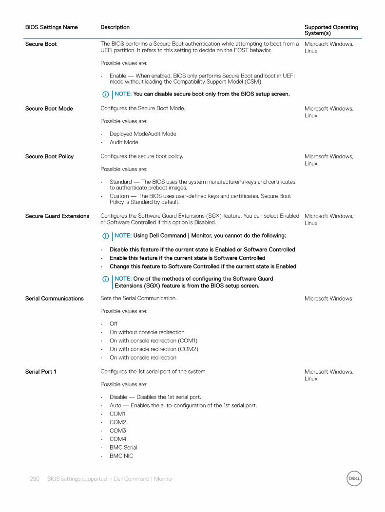
BIOS Settings Name Description Supported Operating System(s)
Secure Boot The BIOS performs a Secure Boot authentication while attempting to boot from a UEFI partition. It refers to this setting to decide on the POST behavior.
Possible values are:
• Enable — When enabled, BIOS only performs Secure Boot and boot in UEFI mode without loading the Compatibility Support Model (CSM).
NOTE: You can disable secure boot only from the BIOS setup screen.
Microsoft Windows, Linux
Secure Boot Mode Configures the Secure Boot Mode.
Possible values are:
• Deployed ModeAudit Mode
• Audit Mode
Microsoft Windows, Linux
Secure Boot Policy Configures the secure boot policy.
Possible values are:
• Standard — The BIOS uses the system manufacturer's keys and certificates to authenticate preboot images.
• Custom — The BIOS uses user-defined keys and certificates. Secure Boot Policy is Standard by default.
Microsoft Windows, Linux
Secure Guard Extensions Configures the Software Guard Extensions (SGX) feature. You can select Enabled or Software Controlled if this option is Disabled.
NOTE: Using Dell Command | Monitor, you cannot do the following:
• Disable this feature if the current state is Enabled or Software Controlled
• Enable this feature if the current state is Software Controlled
• Change this feature to Software Controlled if the current state is Enabled
NOTE: One of the methods of configuring the Software Guard Extensions (SGX) feature is from the BIOS setup screen.
Microsoft Windows, Linux
Serial Communications Sets the Serial Communication.
Possible values are:
• Off
• On without console redirection
• On with console redirection (COM1)
• On with console redirection (COM2)
• On with console redirection
Microsoft Windows
Serial Port 1 Configures the 1st serial port of the system.
Possible values are:
• Disable — Disables the 1st serial port.
• Auto — Enables the auto-configuration of the 1st serial port.
• COM1
• COM2
• COM3
• COM4
• BMC Serial
• BMC NIC
Microsoft Windows, Linux
290 BIOS settings supported in Dell Command | Monitor

BIOS Settings Name Description Supported Operating System(s)
• RAC
• COM1BMC
• RS232
• RS422
• RS485
Serial Port 2 Configures the 2nd serial port of the system.
Possible values are:
• Disable — Disables the 2nd serial port.
• Auto — Enables the auto-configuration of the 2nd serial port.
• COM2
• COM4
• RS232
• RS422
• RS485
Microsoft Windows, Linux
Serial Port 3 Configures the 3rd serial port of the system.
Possible values are:
• Disable — Disables the 3rd serial port.
• Auto — Enables the auto-configuration of the 3rd serial port.
• RS232
• RS422
• RS485
Microsoft Windows, Linux
Serial Port 4 Configures the 4th serial port of the system.
Possible values are:
• Disable — Disables the 4th serial port.
• Auto — Enables the auto-configuration of the 4th serial port.
• RS232
• RS422
• RS485
Microsoft Windows, Linux
Serial Port 5 Configures the system’s 5th serial port.
Possible values are:
• Disable — Disables the 5th serial port.
• Auto — Enables the auto-configuration of the 5th serial port.
Microsoft Windows, Linux
Serial Port 6 Configures the 6th serial port of the system.
Possible values are:
• Disable — Disables the 6th serial port.
• Auto — Enables the auto-configuration of the 6th serial port.
Microsoft Windows, Linux
SERR DMI Message Enables or Disables SERR DMI Messages.
Possible values are:
• Off
Microsoft Windows, Linux
BIOS settings supported in Dell Command | Monitor 291
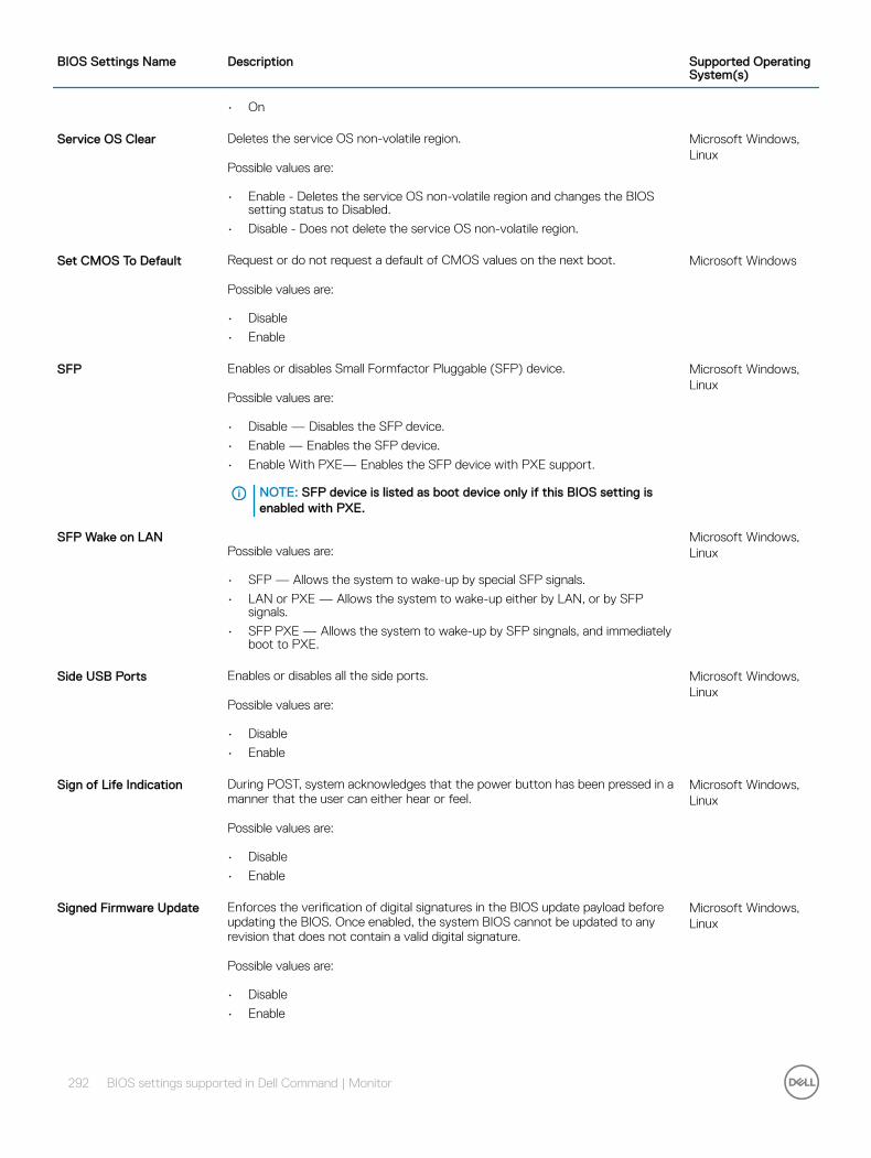
BIOS Settings Name Description Supported Operating System(s)
• On
Service OS Clear Deletes the service OS non-volatile region.
Possible values are:
• Enable - Deletes the service OS non-volatile region and changes the BIOS setting status to Disabled.
• Disable - Does not delete the service OS non-volatile region.
Microsoft Windows, Linux
Set CMOS To Default Request or do not request a default of CMOS values on the next boot.
Possible values are:
• Disable
• Enable
Microsoft Windows
SFP Enables or disables Small Formfactor Pluggable (SFP) device.
Possible values are:
• Disable — Disables the SFP device.
• Enable — Enables the SFP device.
• Enable With PXE— Enables the SFP device with PXE support.
NOTE: SFP device is listed as boot device only if this BIOS setting is enabled with PXE.
Microsoft Windows, Linux
SFP Wake on LANPossible values are:
• SFP — Allows the system to wake-up by special SFP signals.
• LAN or PXE — Allows the system to wake-up either by LAN, or by SFP signals.
• SFP PXE — Allows the system to wake-up by SFP singnals, and immediately boot to PXE.
Microsoft Windows, Linux
Side USB Ports Enables or disables all the side ports.
Possible values are:
• Disable
• Enable
Microsoft Windows, Linux
Sign of Life Indication During POST, system acknowledges that the power button has been pressed in a manner that the user can either hear or feel.
Possible values are:
• Disable
• Enable
Microsoft Windows, Linux
Signed Firmware Update Enforces the verification of digital signatures in the BIOS update payload before updating the BIOS. Once enabled, the system BIOS cannot be updated to any revision that does not contain a valid digital signature.
Possible values are:
• Disable
• Enable
Microsoft Windows, Linux
292 BIOS settings supported in Dell Command | Monitor
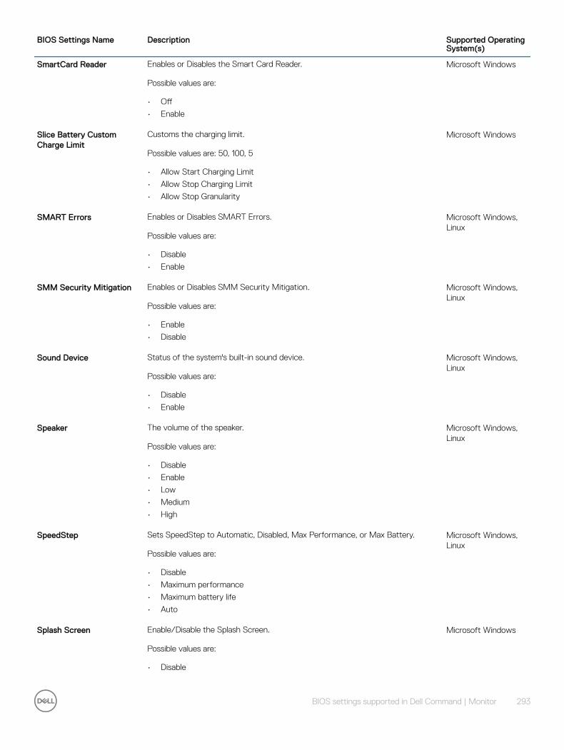
BIOS Settings Name Description Supported Operating System(s)
SmartCard Reader Enables or Disables the Smart Card Reader.
Possible values are:
• Off
• Enable
Microsoft Windows
Slice Battery Custom Charge Limit
Customs the charging limit.
Possible values are: 50, 100, 5
• Allow Start Charging Limit
• Allow Stop Charging Limit
• Allow Stop Granularity
Microsoft Windows
SMART Errors Enables or Disables SMART Errors.
Possible values are:
• Disable
• Enable
Microsoft Windows, Linux
SMM Security Mitigation Enables or Disables SMM Security Mitigation.
Possible values are:
• Enable
• Disable
Microsoft Windows, Linux
Sound Device Status of the system's built-in sound device.
Possible values are:
• Disable
• Enable
Microsoft Windows, Linux
Speaker The volume of the speaker.
Possible values are:
• Disable
• Enable
• Low
• Medium
• High
Microsoft Windows, Linux
SpeedStep Sets SpeedStep to Automatic, Disabled, Max Performance, or Max Battery.
Possible values are:
• Disable
• Maximum performance
• Maximum battery life
• Auto
Microsoft Windows, Linux
Splash Screen Enable/Disable the Splash Screen.
Possible values are:
• Disable
Microsoft Windows
BIOS settings supported in Dell Command | Monitor 293
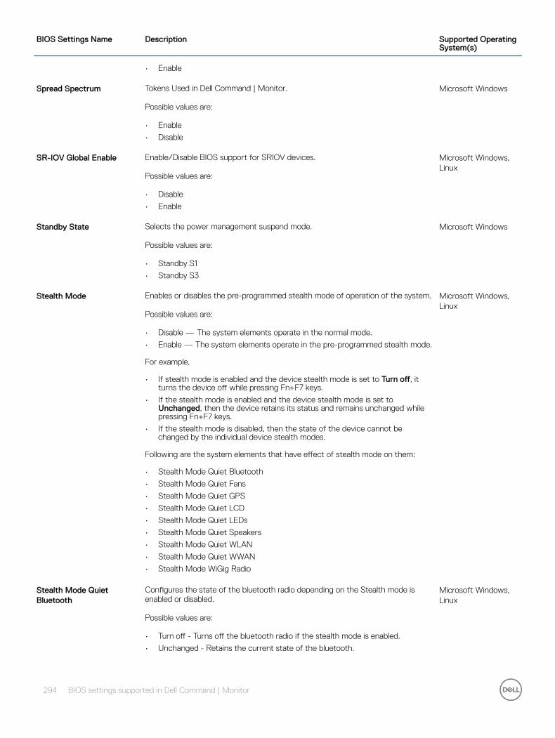
BIOS Settings Name Description Supported Operating System(s)
• Enable
Spread Spectrum Tokens Used in Dell Command | Monitor.
Possible values are:
• Enable
• Disable
Microsoft Windows
SR-IOV Global Enable Enable/Disable BIOS support for SRIOV devices.
Possible values are:
• Disable
• Enable
Microsoft Windows, Linux
Standby State Selects the power management suspend mode.
Possible values are:
• Standby S1
• Standby S3
Microsoft Windows
Stealth Mode Enables or disables the pre-programmed stealth mode of operation of the system.
Possible values are:
• Disable — The system elements operate in the normal mode.
• Enable — The system elements operate in the pre-programmed stealth mode.
For example,
• If stealth mode is enabled and the device stealth mode is set to Turn off, it turns the device off while pressing Fn+F7 keys.
• If the stealth mode is enabled and the device stealth mode is set to Unchanged, then the device retains its status and remains unchanged while pressing Fn+F7 keys.
• If the stealth mode is disabled, then the state of the device cannot be changed by the individual device stealth modes.
Following are the system elements that have effect of stealth mode on them:
• Stealth Mode Quiet Bluetooth
• Stealth Mode Quiet Fans
• Stealth Mode Quiet GPS
• Stealth Mode Quiet LCD
• Stealth Mode Quiet LEDs
• Stealth Mode Quiet Speakers
• Stealth Mode Quiet WLAN
• Stealth Mode Quiet WWAN
• Stealth Mode WiGig Radio
Microsoft Windows, Linux
Stealth Mode Quiet Bluetooth
Configures the state of the bluetooth radio depending on the Stealth mode is enabled or disabled.
Possible values are:
• Turn off - Turns off the bluetooth radio if the stealth mode is enabled.
• Unchanged - Retains the current state of the bluetooth.
Microsoft Windows, Linux
294 BIOS settings supported in Dell Command | Monitor

BIOS Settings Name Description Supported Operating System(s)
Stealth Mode Quiet Fans Configures the state of the fans depending on the Stealth mode is enabled or disabled.
Possible values are:
• Turn off - Turns off the fan if the stealth mode is enabled.
• Unchanged - Retains the current state of the fan.
Microsoft Windows, Linux
Stealth Mode Quiet GPS Configures the state of the GPS radio depending on the Stealth mode is enabled or disabled.
Possible values are:
• Turn off - Turns off the GPS radio if the stealth mode is enabled.
• Unchanged - Retains the current state of the GPS radio.
Microsoft Windows, Linux
Stealth Mode Quiet LCD Configures the state of the LCD screen backlight depending on the Stealth mode is enabled or disabled.
Possible values are:
• Turn off - Turns off the LCD screen backlight if the stealth mode is enabled.
• Unchanged - Retains the current state of the LCD screen backlight.
Microsoft Windows, Linux
Stealth Mode Quiet LEDs Configures the state of the LEDs depending on the Stealth mode is enabled or disabled.
Possible values are:
• Turn off - Turns off the system LEDs if the stealth mode is enabled.
• Unchanged - Retains the current state of the system LEDs.
Microsoft Windows, Linux
Stealth Mode Quiet Speakers
Configures the state of the onboard speakers depending on the Stealth mode is enabled or disabled.
Possible values are:
• Turn off - Turns off the onboard speakers if the stealth mode is enabled.
• Unchanged - Retains the current state of the onboard speakers.
Microsoft Windows, Linux
Stealth Mode Quiet WLAN Configures the state of the WLAN (and WiGig) radio depending on the Stealth mode is enabled or disabled.
Possible values are:
• Turn off - Turns off the WLAN if the stealth mode is enabled.
• Unchanged - Retains the current state of the WLAN.
Microsoft Windows, Linux
Stealth Mode Quiet WWAN Configures the state of the WWAN (and WiGig) radio depending on the Stealth mode is enabled or disabled.
Possible values are:
• Turn off - Turns off the WWAN (and WiGig) radio if the stealth mode is enabled.
• Unchanged - Retains the current state of the WWAN (and WiGig) radio.
Microsoft Windows, Linux
Stealth Mode WiGig Radio Configures or displays the state of Wireless Gigabit Alliance (WiGig) radio depending on the Unobtrusive mode or stealth mode is enabled or disabled.
Microsoft Windows, Linux
BIOS settings supported in Dell Command | Monitor 295
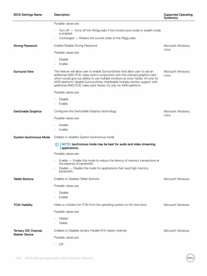
BIOS Settings Name Description Supported Operating System(s)
Possible values are:
• Turn off — Turns off the WiGig radio if the Unobtrusive mode or stealth mode is enabled.
• Unchanged — Retains the current state of the Wigig radio.
Strong Password Enable/Disable Strong Password.
Possible values are:
• Disable
• Enable
Microsoft Windows, Linux
Surround View This feature will allow user to enable SurroundView that allow user to use an additional AMD PCIE video card in conjunction with the onboard graphics card which would give you ability to use multiple monitors at once. Notes: it's only for AMD platform/ disable SurroundView thatdisable multiple monitor support with additional AMD PCIE video card. Notes: it's only for AMD platform.
Possible values are:
• Disable
• Enable
Microsoft Windows, Linux
Switchable Graphics Configures the Switchable Graphics technology.
Possible values are:
• Disable
• Enable
Microsoft Windows, Linux
System Isochronous Mode Enables or disables System Isochronous mode.
NOTE: Isochronous mode may be best for audio and video streaming applications.
Possible values are:
• Enable — Enable this mode to reduce the latency of memory transactions at the expense of bandwidth.
• Disable — Disable this mode for applications that need high memory bandwidth.
Tablet Buttons Enables or Disables Tablet Buttons.
Possible values are:
• Disable
• Enable
Microsoft Windows
TCM Visibility Hides or unhides the TCM from the operating system on the next boot.
Possible values are:
• Hidden
• Visible
Microsoft Windows
Tertiary IDE Channel, Master Device
Enables or Disables tertiary Parallel ATA master channel.
Possible values are:
• Off
Microsoft Windows
296 BIOS settings supported in Dell Command | Monitor

BIOS Settings Name Description Supported Operating System(s)
• Auto
Tertiary IDE Channel, Slave Device
Enables or Disables tertiary Parallel ATA master channel.
Possible values are:
• Off
• Auto
Microsoft Windows
Thunderbolt Enables or disables the thunderbolt controller in the system.
Possible values are:
• Disable
• Enable
Microsoft Windows, Linux
Thunderbolt Boot Support Enables or disables booting from the Thunderbolt device.
Possible values are:
• Disable
• Enable
Microsoft Windows, Linux
Thunderbolt Pre Boot Module
Enables or disables OROMs and pre-boot UEFI drivers provided by Thunderbolt devices or PCIe devices.
Possible values are:
• Disable
• Enable
Microsoft Windows, Linux
Thunderbolt Security Level Configures the thunderbolt security level.
Possible values are:
• No Security — Disables the thunderbolt security.
• User Authorization — Allows minimum user notification. Connection manager requests connection approval from the host software, based on the unique ID of the connecting device, auto approval might or might not be given.
• Secure Connect — Allows one-time saved key device. Connection manager requests connection approval from the host software; approval is given only if the host challenge to device is acceptable.
• Display Port Only — Allows to connect only display port.
Microsoft Windows, Linux
Touch Screen Enables or disables the touchscreen of the device.
Possible values are:
• Disable
• Enable
Microsoft Windows, Linux
TPM Hash Algorithm Selects the hash algorithm used for TPM 2.0 measurements.
Possible values are:
• 0 = SHA-1
• 1 = SHA-256
• 2 = SHA-384
• 3 = SHA-512
Microsoft Windows, Linux
BIOS settings supported in Dell Command | Monitor 297

BIOS Settings Name Description Supported Operating System(s)
NOTE: This value cannot be changed if the TPM is already owned.
Trusted Execution New processor execution mode and BIOS hooks to enable a protected execution environment and main memory protection.
Possible values are:
• On
• Off
Microsoft Windows, Linux
Trusted Platform Module Enables or Disables the Trusted Platform Module (TPM).
Possible values are:
• Enable
• Disable
Microsoft Windows, Linux
Trusted Platform Module Activation
This property is used to activate the TPM if it is deactivated, unowned and a BIOS Admin password is set and has been verified; otherwise this property reports the status of the TPM Activation BIOS option.
Possible values are:
• Deactivate
• Activate
Microsoft Windows, Linux
TPM PPI ACPI Support Enables or disables the TPM ACPI physical presence commands.
Possible values are:
• Enable
• Disable
Microsoft Windows, Linux
TPM PPI Provision Override
Enables or disables the physical presence for the ACPI TPM PPI provision operations.
Possible values are:
• Enable
• Disable
Microsoft Windows, Linux
TPM PPI Deprovision Override
Enables or disables the physical presence for the ACPI TPM PPI deprovision operations.
Possible values are:
• Enable
• Disable
Microsoft Windows, Linux
Type-C Battery Overload Protection
Configures the maximum power for type-C connector.
Possible values are:
• 0 – 7.5 Watts
• 1 – 15 Watts
Microsoft Windows, Linux
UART Power Down Allow the operating system to power down or Prohibit OS from powering down UART.
Microsoft Windows
298 BIOS settings supported in Dell Command | Monitor
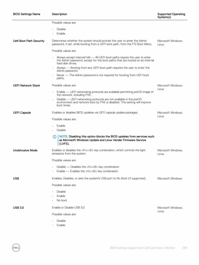
BIOS Settings Name Description Supported Operating System(s)
Possible values are:
• Disable
• Enable
Uefi Boot Path Security Determines whether the system should prompt the user to enter the Admin password, if set, while booting from a UEFI boot path, from the F12 Boot Menu.
Possible values are:
• Always except internal hdd — All UEFI boot paths require the user to enter the Admin password, except for the boot paths that are hosted on an internal hard disk drives.
• Always — Booting from any UEFI boot path requires the user to enter the Admin password.
• Never — The Admin password is not required for booting from UEFI boot paths.
Microsoft Windows, Linux
UEFI Network Stack Possible values are:
• Enable — UEFI networking protocols are available permitting preOS image of the network, including PXE.
• Disable — UEFI networking protocols are not available in the preOS environment and network boot by PXE is disabled. This setting will improve boot times.
Microsoft Windows, Linux
UEFI Capsule Enables or disables BIOS updates via UEFI capsule update packages.
Possible values are:
• Enable
• Disable
NOTE: Disabling this option blocks the BIOS updates from services such as Microsoft Windows Update and Linux Vender Firmware Service (LVFS).
Microsoft Windows, Linux
Unobtrusive Mode Enables or disables the <Fn><B> key combination, which controls the light emissions from the system.
Possible values are:
• Disable — Disables the <fn><B> key combination
• Enable — Enables the <fn><B> key combination
Microsoft Windows, Linux
USB Enables, Disables, or sets the system's USB port to No Boot (if supported).
Possible values are:
• Disable
• Enable
• No boot
Microsoft Windows
USB 3.0 Enable or Disable USB 3.0
Possible values are:
• Disable
• Enable
Microsoft Windows, Linux
BIOS settings supported in Dell Command | Monitor 299

BIOS Settings Name Description Supported Operating System(s)
USB Emulation Enables or Disables USB keyboard and mouse support for Operating systems that do not natively support USB keyboards and mice.
Possible values are:
• Enable
• Disable
Microsoft Windows, Linux
USB Flash Drive EmulationPossible values are:
• Auto
• Floppy
• HD only
Microsoft Windows
USB Port 0 Enables or Disables USB Port 00.
Possible values are:
• Disable
• Enable
Microsoft Windows, Linux
USB Port 1 Enables or Disables USB Port 01.
Possible values are:
• Disable
• Enable
Microsoft Windows, Linux
USB Port 2 Enables or Disables USB Port 02.
Possible values are:
• Disable
• Enable
Microsoft Windows, Linux
USB Port 3 Enables or Disables USB Port 03.
Possible values are:
• Disable
• Enable
Microsoft Windows, Linux
USB Port 4 Enables or Disables USB Port 04.
Possible values are:
• Disable
• Enable
Microsoft Windows, Linux
USB Port 5 Enables or Disables USB Port 05.
Possible values are:
• Disable
• Enable
Microsoft Windows, Linux
USB Port 6 Enables or Disables USB Port 06. Microsoft Windows, Linux
300 BIOS settings supported in Dell Command | Monitor

BIOS Settings Name Description Supported Operating System(s)
Possible values are:
• Disable
• Enable
USB Port 7 Enables or Disables USB Port 07.
Possible values are:
• Disable
• Enable
MMicrosoft Windows, Linux
USB Port 8 Enables or Disables USB Port 08.
Possible values are:
• Disable
• Enable
Microsoft Windows, Linux
USB Port 9 Enables or Disables USB Port 09.
Possible values are:
• Disable
• Enable
Microsoft Windows, Linux
USB Port 10 Enables or Disables USB Port 10.
Possible values are:
• Disable
• Enable
Microsoft Windows
USB Port 11 Enables or Disables USB Port 11.
Possible values are:
• Disable
• Enable
Microsoft Windows
USB Port 12 Enables or Disables USB Port 12.
Possible values are:
• Disable
• Enable
Microsoft Windows
USB Port 13 Enables or Disables USB Port 13.
Possible values are:
• Disable
• Enable
Microsoft Windows
USB Port 14 Enables or Disables USB Port 14.
Possible values are:
• Disable
• Enable
Microsoft Windows
BIOS settings supported in Dell Command | Monitor 301

BIOS Settings Name Description Supported Operating System(s)
USB Port 15 Enables or Disables USB Port 15.
Possible values are:
• Disable
• Enable
Microsoft Windows
USB Port 16 Enables or Disables USB Port 16.
Possible values are:
• Enable
• Disable
Microsoft Windows, Linux
USB Port 17 Enables or Disables USB Port 17.
Possible values are:
• Enable
• Disable
Microsoft Windows, Linux
USB Port 18 Enables or Disables USB Port 18.
Possible values are:
• Enable
• Disable
Microsoft Windows, Linux
USB Port 19 Enables or Disables USB Port 19.
Possible values are:
• Enable
• Disable
Microsoft Windows, Linux
USB Port 20 Enables or Disables USB Port 20.
Possible values are:
• Disable
• Enable
Microsoft Windows, Linux
USB Port 21 Enables or Disables USB Port 21.
Possible values are:
• Disable
• Enable
Microsoft Windows, Linux
USB Port 22 Enables or Disables USB Port 22.
Possible values are:
• Disable
• Enable
Microsoft Windows, Linux
USB Port 23 Enables or Disables USB Port 23.
Possible values are:
• Disable
Microsoft Windows, Linux
302 BIOS settings supported in Dell Command | Monitor

BIOS Settings Name Description Supported Operating System(s)
• Enable
USB Port 24 Enables or Disables USB Port 24.
Possible values are:
• Enable
• Disable
Microsoft Windows, Linux
USB Port 25 Enables or Disables USB Port 25.
Possible values are:
• Enable
• Disable
Microsoft Windows, Linux
USB Port 26 Enables or Disables USB Port 26.
Possible values are:
• Enable
• Disable
Microsoft Windows, Linux
USB Port 27 Enables or Disables USB Port 27.
Possible values are:
• Enable
• Disable
Microsoft Windows, Linux
USB Port 28 Enables or Disables USB Port 28.
Possible values are:
• Enable
• Disable
Microsoft Windows, Linux
USB Port 29 Enables or Disables USB Port 29.
Possible values are:
• Enable
• Disable
Microsoft Windows, Linux
USB Provision Enables or disables provisioning of Intel AMT from a USB storage device.
Possible values are:
• Enabled — Intel AMT can be provisioned using the local provisioning file via a USB storage device.
• Disabled — Provisioning of Intel AMT from a USB storage device is blocked.
Microsoft Windows, Linux
USB PowerShare Enables or disables the USB PowerShare feature.
Possible values are:
• Disable
• Enable
Microsoft Windows, Linux
User Accessible USB Ports Enables or disables user accessible USB ports. Microsoft Windows
BIOS settings supported in Dell Command | Monitor 303

BIOS Settings Name Description Supported Operating System(s)
Possible values are:
• All off
• Back only
• All on
USB Wake from S4 Enables or disables the USB wake from s4 power state of the system.
Possible values are:
• Enable - Enables the USB wake from s4 power state of the system.
• Disable - Disables the USB wake from s4 power state of the system.
Microsoft Windows, Linux
USB Wake Support Enables or Disables USB Wake setting.
Possible values are:
• Disable
• Enable
Microsoft Windows, Linux
Video Expansion Enables or Disables Video Expansion.
Possible values are:
• Disable
• Enable
Microsoft Windows
Video Memory Size Enables or Disables Video Expansion.
Possible values are:
• Off
• Auto
• 1MB
• 8MB
• 16MB
• 32MB
• 64MB
• 128MB
• 256MB
• 512MB
• 1GB
Microsoft Windows
VT for Direct IO Intel Virtualization Technology for Direct I/O (VT-d) – new chipset feature that enhances I/O support (DMA) when running a Virtual Machine Monitor.
Possible values are:
• Disable
• Enable
Microsoft Windows, Linux
Wake on Dock Enables or disables waking the system when a docking connection is made.
Possible values are:
• Disable
• Enable
Microsoft Windows, Linux
304 BIOS settings supported in Dell Command | Monitor

BIOS Settings Name Description Supported Operating System(s)
Wake-On-LAN Defines the wake-on-LAN feature. This property defines whether Wakeup On LAN is disabled, enabled for on-board NIC only or enabled for add-in NIC only. If Enabled with boot to NIC option is selected, the system boots from the NIC boot-ROM upon a remote wakeup.
Possible values are:
• Disable
• Enable_AIC
• Enable_OnBoard
• Enable All
• LAN or WLAN
• WLAN only
• LAN with PXE boot
Microsoft Windows
Wake on 2nd LAN (RJ-45/SFP)
Defines the wake on 2nd LAN feature.
Possible values are: 1, 2, 3
• Disabled
• LanOnly
• LanWithPxeBoot
Microsoft Windows
Wake-On-LAN Boot Override
If enabled then when the system powers on due to a Wake-on-LAN event, the NIC boot-ROM is automatically given the highest boot priority, pre-pending the PXE boot-ROM to the system’s current boot sequence. If the system powers on due to some other event, this selection does not influence the boot sequence. If disabled then the boot override feature is disabled and the system boot sequence is in effect for all types of system power on.
Possible values are:
• Disable
• Enable
Microsoft Windows
Warnings And Errors During POST the system continues to boot or pauses when warnings or errors are detected. This feature can be used for the remotely managed systems that do not have a keyboard or a consoles available for use.
Possible values are:
• 1 = Disabled – System pauses for the user to respond when warnings or errors are detected.
• 2 = Continue on Warnings – System continues to boot when warnings are detected, but pauses for the user to respond when errors are detected.
• 3 = Continue on Warnings and Errors – System continues to boot when warnings or errors are detected.
Microsoft Windows, Linux
Watchdog Timer The system will/will not reboot/reset if the watchdog timer expires
Possible values are:
• Disable
• Enable
Microsoft Windows, Linux
Watchdog Timer The system will/will not reboot/reset if the watchdog timer expires
Possible values are:
• Disable
Microsoft Windows
BIOS settings supported in Dell Command | Monitor 305

BIOS Settings Name Description Supported Operating System(s)
• Enable
Wireless Adapter Enables or disables Wireless Adapter.
Possible values are:
• Disable
• Enable
MMicrosoft Windows, Linux
Wireless Device If disabled then wireless devices are always disabled.
If set to APP then wireless devices can be controlled by an application such as QuickSet
If set to Hotkey then wireless devices can be controlled by an application such as QuickSet
Possible values are:
• Disable
• APP
• Hotkey
Microsoft Windows
WiFi Catcher Changes Permits or Denies WiFi Catcher changes. If the administrator password is not set, this setting will have no effect.
Possible values are:
• Deny
• Permit
Microsoft Windows
WiFi Locator Enables or Disables the WiFi Locator.
Possible values are:
• Disable
• Enable
Microsoft Windows
Wireless LAN Enables or Disables the wireless LAN module.
Possible values are:
• Disable
• Enable
Microsoft Windows, Linux
Wireless Radio Control Switch
Enables or disables the Wireless Gigabit (WiGig) radio control switch on the dock.
Possible values are:
• Disable
• Enable
Microsoft Windows, Linux
Wireless Switch Bluetooth Control
Enables or Disables wireless switch Bluetooth control.
Possible values are:
• Disable
• Enable
Microsoft Windows, Linux
306 BIOS settings supported in Dell Command | Monitor
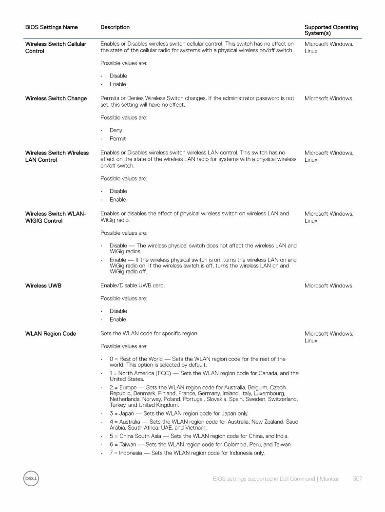
BIOS Settings Name Description Supported Operating System(s)
Wireless Switch Cellular Control
Enables or Disables wireless switch cellular control. This switch has no effect on the state of the cellular radio for systems with a physical wireless on/off switch.
Possible values are:
• Disable
• Enable
Microsoft Windows, Linux
Wireless Switch Change Permits or Denies Wireless Switch changes. If the administrator password is not set, this setting will have no effect.
Possible values are:
• Deny
• Permit
Microsoft Windows
Wireless Switch Wireless LAN Control
Enables or Disables wireless switch wireless LAN control. This switch has no effect on the state of the wireless LAN radio for systems with a physical wireless on/off switch.
Possible values are:
• Disable
• Enable
Microsoft Windows, Linux
Wireless Switch WLAN-WIGIG Control
Enables or disables the effect of physical wireless switch on wireless LAN and WiGig radio.
Possible values are:
• Disable — The wireless physical switch does not affect the wireless LAN and WiGig radios.
• Enable — If the wireless physical switch is on, turns the wireless LAN on and WiGig radio on. If the wireless switch is off, turns the wireless LAN on and WiGig radio off.
Microsoft Windows, Linux
Wireless UWB Enable/Disable UWB card.
Possible values are:
• Disable
• Enable
Microsoft Windows
WLAN Region Code Sets the WLAN code for specific region.
Possible values are:
• 0 = Rest of the World — Sets the WLAN region code for the rest of the world. This option is selected by default.
• 1 = North America (FCC) — Sets the WLAN region code for Canada, and the United States.
• 2 = Europe — Sets the WLAN region code for Australia, Belgium, Czech Republic, Denmark, Finland, France, Germany, Ireland, Italy, Luxembourg, Netherlands, Norway, Poland, Portugal, Slovakia, Spain, Sweden, Switzerland, Turkey, and United Kingdom.
• 3 = Japan — Sets the WLAN region code for Japan only.
• 4 = Australia — Sets the WLAN region code for Australia, New Zealand, Saudi Arabia, South Africa, UAE, and Vietnam.
• 5 = China South Asia — Sets the WLAN region code for China, and India.
• 6 = Taiwan — Sets the WLAN region code for Colombia, Peru, and Taiwan.
• 7 = Indonesia — Sets the WLAN region code for Indonesia only.
Microsoft Windows, Linux
BIOS settings supported in Dell Command | Monitor 307
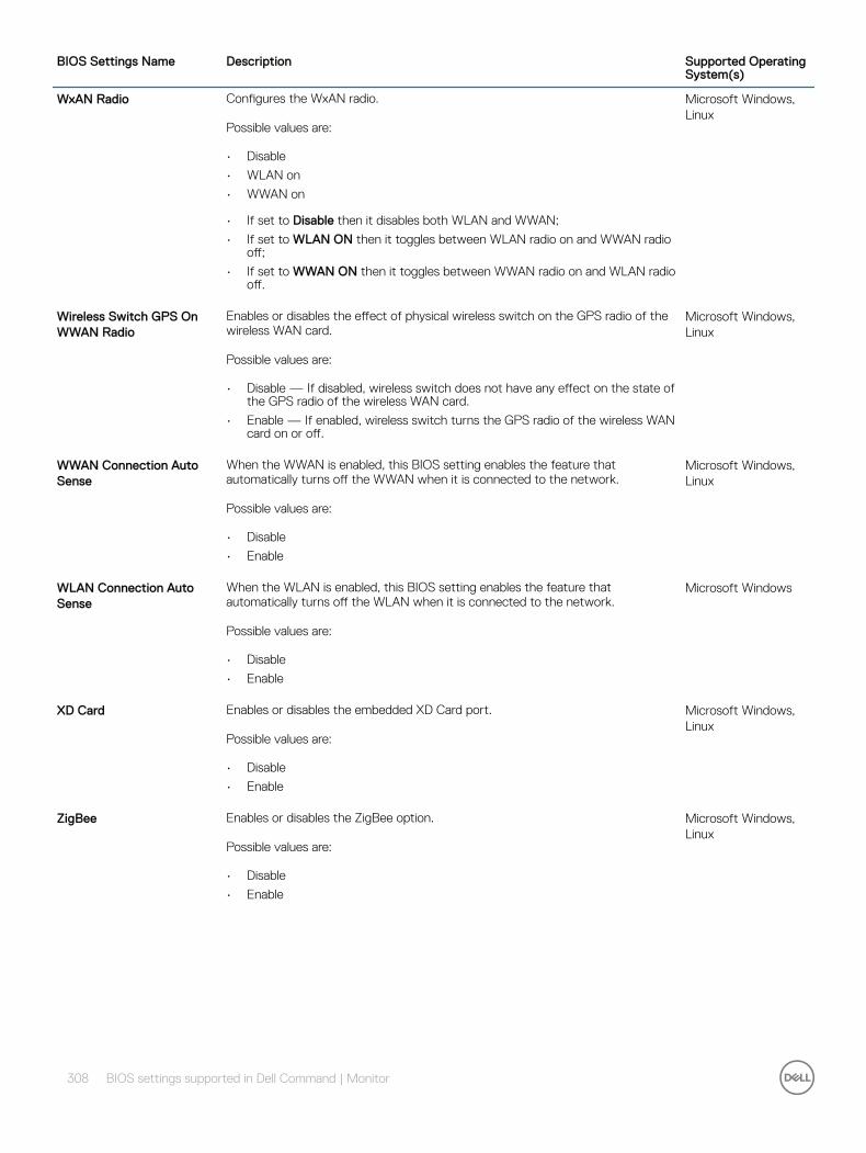
BIOS Settings Name Description Supported Operating System(s)
WxAN Radio Configures the WxAN radio.
Possible values are:
• Disable
• WLAN on
• WWAN on
• If set to Disable then it disables both WLAN and WWAN;
• If set to WLAN ON then it toggles between WLAN radio on and WWAN radio off;
• If set to WWAN ON then it toggles between WWAN radio on and WLAN radio off.
Microsoft Windows, Linux
Wireless Switch GPS On WWAN Radio
Enables or disables the effect of physical wireless switch on the GPS radio of the wireless WAN card.
Possible values are:
• Disable — If disabled, wireless switch does not have any effect on the state of the GPS radio of the wireless WAN card.
• Enable — If enabled, wireless switch turns the GPS radio of the wireless WAN card on or off.
Microsoft Windows, Linux
WWAN Connection Auto Sense
When the WWAN is enabled, this BIOS setting enables the feature that automatically turns off the WWAN when it is connected to the network.
Possible values are:
• Disable
• Enable
Microsoft Windows, Linux
WLAN Connection Auto Sense
When the WLAN is enabled, this BIOS setting enables the feature that automatically turns off the WLAN when it is connected to the network.
Possible values are:
• Disable
• Enable
Microsoft Windows
XD Card Enables or disables the embedded XD Card port.
Possible values are:
• Disable
• Enable
Microsoft Windows, Linux
ZigBee Enables or disables the ZigBee option.
Possible values are:
• Disable
• Enable
Microsoft Windows, Linux
308 BIOS settings supported in Dell Command | Monitor

Alerts in Dell Command | Monitor Local alerting involves displaying user messages and writing to the Windows event log. Remote alerting is accomplished through WMI indications. When Dell Command | Monitor detects an event, it generates an alert, which can be transmitted through the WMI service to a remote management application that is subscribed to that alert type.
When an alert is generated, Dell Command | Monitor supports following types of notification:
For Windows,
• Windows event log— available at Windows Logs > System
• CIM Indication— available through DCIM_AlerIndication class
• SNMP traps — available through 10909.mib file
• History — available through DCIM_LogEntry class instances
For Linux,
• Syslog — available at /var/log
• CIM Indication— available through DCIM_AlerIndication class
• Application log— available through DCIM_LogEntry class
• History — available through DCIM_LogEntry class instances
In Dell Command | Monitor, each type of event (for example, CurrentProbe, TemperatureProbe, Smart, and so on) that gets logged is provided with an unique event ID number. The events have unique IDs to allow log scraping; this way you can programmatically look at the event log and determine what Dell Command | Monitor events have occurred.
In Dell Command | Monitor for Windows, you are also provided with an option to receive either a single alert or a limited number of alerts of the occurrence of an event, of a given type. You can mask out specific events and can generate single alert messages for only those events.
NOTE: Configuring the selected events is not supported for Dell Command | Monitor for Linux.
Dell Command | Monitor recognizes the following eight CIM severity levels using perceived severity (represented by integers 0 through 7):
• UNKNOWN = 0
• OTHER = 1
• INFORMATION = 2
• WARNING_DEGRADED = 3
• MINOR = 4
• MAJOR = 5
• CRITICAL = 6
• FATAL_NONRECOVERABLE = 7
NOTE: Events with CRITICAL severity will cause Dell Command | Monitor to shut down the local system.
The lowest WMI severity level that Dell Command | Monitor sends is WARNING_DEGRADED and the highest is CRITICAL. The severities of Dell Command | Monitor events are listed in Table 2-1. Dell Command | Monitor sends local alerting and remote alerting for all the listed events.
7
Alerts in Dell Command | Monitor 309

Table 1. Events Polled by Dell Command | Monitor
Dell Command | Monitor Event (Windows Event Log Number)
Description
AlertTemperatureProbeWarning (1053) Temperature probe has detected a warning value.
AlertTemperatureProbeFailure (1054) Temperature probe has detected a failure value.
AlertTemperatureProbeNonRecoverable (1055)
Temperature probe has detected a non-recoverable value.
FanProbe (1103) A cooling device has exceeded a minor threshold.
AlertCoolingDeviceFailure (1104) Cooling device sensor has detected a failure value.
AlertCoolingDeviceNonRecoverable (1105)
Cooling device sensor has detected a non-recoverable value.
AlertVoltageProbeWarning (1153) Voltage probe has detected a warning value.
AlertVoltageProbeFailure (1154) Voltage probe has detected a failure value.
AlertVoltageProbeNonRecoverable (1155) Voltage probe has detected a non-recoverable value.
CurrentProbe (1203) An electrical current probe has exceeded a minor threshold.
One of the hard-disk drive is running out of free space.
AlertAmperageProbeFailure (1204) Amperage probe has detected a failure value.
AlertAmperageProbeNonRecoverable (1205)
Amperage probe has detected a non-recoverable value.
ChassisIntrusionNormal (1252) Chassis intrusion has returned to normal.
ChassisIntrusion (1254) System chassis intrusion alert.
EccMemory (1403) A memory checksum failure has occurred.
NOTE: This event is not supported on the system running RHEL.
RAIDControllerFailure (1801) A RAID controller has failed.
RAIDControllerOffline (1802) A RAID controller is offline.
RAIDControllerPowerOff (1803) A RAID controller is turned off.
AlertRaidControllerDegraded (1804) A Raid controller has degraded.
PhysicalDiskDegraded (1811) A physical hard-disk drive is degraded.
AlertPhysicalDiskRebuilding (1812) A physical hard-disk drive is rebuilding.
PhysicalDiskFailed (1813) A physical hard-disk drive has failed.
PhysicalDiskOffline (1814) A physical hard-disk drive is offline.
VitualDiskDegraded (1821) A virtual hard-disk drive is degraded.
310 Alerts in Dell Command | Monitor
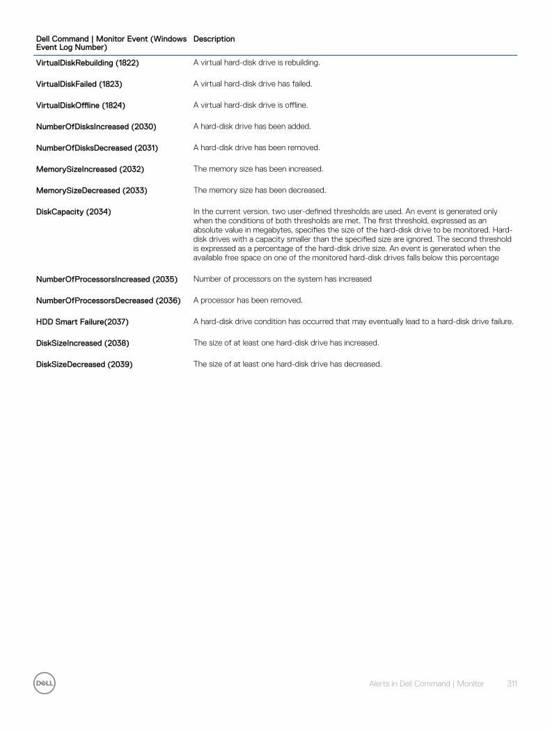
Dell Command | Monitor Event (Windows Event Log Number)
Description
VirtualDiskRebuilding (1822) A virtual hard-disk drive is rebuilding.
VirtualDiskFailed (1823) A virtual hard-disk drive has failed.
VirtualDiskOffline (1824) A virtual hard-disk drive is offline.
NumberOfDisksIncreased (2030) A hard-disk drive has been added.
NumberOfDisksDecreased (2031) A hard-disk drive has been removed.
MemorySizeIncreased (2032) The memory size has been increased.
MemorySizeDecreased (2033) The memory size has been decreased.
DiskCapacity (2034) In the current version, two user-defined thresholds are used. An event is generated only when the conditions of both thresholds are met. The first threshold, expressed as an absolute value in megabytes, specifies the size of the hard-disk drive to be monitored. Hard-disk drives with a capacity smaller than the specified size are ignored. The second threshold is expressed as a percentage of the hard-disk drive size. An event is generated when the available free space on one of the monitored hard-disk drives falls below this percentage
NumberOfProcessorsIncreased (2035) Number of processors on the system has increased
NumberOfProcessorsDecreased (2036) A processor has been removed.
HDD Smart Failure(2037) A hard-disk drive condition has occurred that may eventually lead to a hard-disk drive failure.
DiskSizeIncreased (2038) The size of at least one hard-disk drive has increased.
DiskSizeDecreased (2039) The size of at least one hard-disk drive has decreased.
Alerts in Dell Command | Monitor 311

Sample scriptsTo execute various functionalities in Dell Command | Monitor, refer to the sample PowerShell and VB scripts available at dell.com/techcenter, Dell Command | Monitor page.
8
312 Sample scripts