delivery efficiency of the jaga low h o heat exchanger in ... · gt-140002 january 2014 delivery...
TRANSCRIPT
GT-140002
January 2014
Delivery efficiency of the Jaga Low H2O heat
exchanger in a Tempo enclosure
Determination of the delivery efficiency for a quality declaration for the ISSO database

GT-140002
January 2014
Delivery efficiency of the Jaga Low H2O heat
exchanger in a Tempo enclosure
© 2014 Kiwa N.V. All rights reserved. No part of this publication may be reproduced, stored in a retrieval system, or transmitted, in any form or by any means, whether electronic, mechanical, photocopying, recording, or in any other way, without the prior written permission of the publisher.
Kiwa Technology B.V.
Wilmersdorf 50
Postbus 137
7300 AC Apeldoorn
Tel. 055 539 33 93
Fax 055 539 34 94
www.kiwatechnology.nl
Determination of the delivery efficiency for a quality declaration for the ISSO database
Colophon
Title Delivery efficiency of the Jaga Low H2O
heat exchanger in a Tempo enclosure Project number 130901030 Project manager ir. M.J. Kippers Client Jaga-Konvektco Nederland B.V.
J. Verdonck Quality assurer(s) ir. J.C. de Laat Author(s) ing. E.F.J. Fennema, ir. M.J. Kippers
This report is not public and is only provided to the clients of the contract research project/consulting project. Any further distribution will be by the client itself.

GT-140002
© Kiwa N.V.
January 2014
- 1 -
Summary
Jaga-Konvektco has developed the Low H2O heat exchanger, which provides energy
savings compared to a standard radiator. Jaga likes to use this energy saving as a
selling point. Jaga intends to have the Low H2O heat exchanger included in the
database that is linked to the energy performance standard (EPN) by means of a
quality certificate. The energy savings of the Low H2O heat exchanger are therefore
also included in the energy performance coefficient calculation. The database with
quality declarations is managed by ISSO (knowledge institute for the installation
sector.)
Using simulations, which are based on national and international standards, and
measurements performed by Jaga-Konvektco, Kiwa Technology has calculated the
energy savings of the Low H2O heat exchanger. The energy savings of the Low H2O
heat exchanger are at least 5%.
The quality declaration for the Low H2O heat exchanger in a Tempo enclosure is set
out in the annex.

GT-140002
© Kiwa N.V.
January 2014
- 2 -
Contents
Summary 1
1 Introduction 3
1.1 Background 3
1.2 Jaga Low H2O heat exchanger with Tempo type 15 enclosure 3
1.3 Task: Calculation of the delivery efficiency of the Low H2O heat exchanger 4
1.4 Report layout 5
2 The Low H2O heat exchanger is more energy efficient than standard radiators 6
2.1 Result is at least 5% energy saving 6
2.2 The delivery efficiency is determined using an annual simulation of the Low H2O heat exchanger in a standard home 7
2.2.1 The simulation is modular 7 2.2.2 Modelling of the Jaga Low H2O 7
Literature list 9
I Calculation of the delivery efficiency 10
II Modelling of the Jaga Low H2O heat exchanger 11
III Quality declaration: delivery efficiency 'lH,em of Jaga Low H2O heat exchanger in a Tempo enclosure 16

GT-140002
© Kiwa N.V.
January 2014
- 3 -
1 Introduction
1.1 Background
The energy performance of a building depends, among other things, on the efficiency
of the delivery system. These delivery systems include the radiators. The energy
performance is calculated on the basis of the "Energy performance standard for
buildings" (EPG, NEN7120).
As standard the EPG assumes default values for the delivery efficiency of delivery
systems under various conditions. However, the standard also offers the alternative to
evaluate the delivery efficiency through a quality declaration. The quality declaration
has the advantage that a distinction can be made between different delivery systems
based on their efficiency. Innovative energy-efficient delivery systems can therefore
make a positive contribution to the calculated energy performance of a building and in
this way are competitive. ISSO (knowledge institute for the installation sector)
assesses the validity of quality declarations and manages the "verified quality
declaration database".
1.2 Jaga Low H2O changer combined with Tempo type 15 enclosure
The Jaga Low H2O Tempo is a heat emission system based on a heat exchanger in
an enclosure as shown in figure 1, 2 and 3.
Figure 1: Jaga Low H2O heat exchanger Figure 2: Jaga enclosure Tempo type 15
NEN 7120 "Energy performance standard for buildings" (EPG)
- based on the European Energy Performance Buildings Directive (EPBD)
The efficiency of delivery systems using default values (standard route)
all delivery systems have the same efficiency
no possibility for evaluating innovative energy-efficient delivery
systems
default values included in NEN 7120
The efficiency of delivery system based on quality declaration
(alternative route)
distinguish between delivery systems in terms of efficiency
recognition for innovative energy-efficient delivery
systems
quality declaration included in the ISSO "verified quality
declaration database"
quality declaration issued by Kiwa
Energy performance of the building

GT-140002
© Kiwa N.V.
January 2014
- 4 -
Figure 3: Jaga Low H2O heat exchanger in Tempo plus type 15 (wall mounted model)
The Low H2O heat exchanger is made of copper tubes and corrugated aluminium
fins. The serial matrix-flow channels (Figure 1) ensure a good heat transfer of central
heating-water to the air. Due to the compact design, the Low H2O heat exchanger
contains relatively little water and steel parts. Thus, the exchanger reacts fast to a
heat demand and does not heat up unnecessarily when the optimum indoor
temperature is reached. The heat exchanger is mounted at the bottom of the
enclosure. Since the beginning of 2014, the Jaga Tempo type 15 conversion has an
insulating layer on the wall side to limit the loss of energy to the outside.
The Jaga exchanger differs from a conventional radiator in the way described below,
which is relevant for the EN7120:
Advantages:
o The surface of the heat exchanger is significantly smaller than a
conventional radiator. This leads to less radiation loss through the
back wall.
o The insulating layer in the enclosure on the wall side limits the
energy losses to the back wall.
o Significantly smaller heat capacity results in a faster response
time for heat output during a 'cold start'.
Disadvantages:
o The lower temperature and smaller surface results in a smaller
radiation component in the Fanger comfort equation.
o The convection losses to the back wall are higher because there
is a bigger air flow along the back wall.
1.3 Task: Calculation of the delivery efficiency of the Low H2O heat
exchanger Jaga-Konvektco has commissioned Kiwa Technology to calculate the delivery
efficiency of the Low H2O heat exchanger mounted in a type 15 Tempo enclosure.
Kiwa Technology has developed a simulation model for this exchanger. The
simulation model is based on an existing model that was also used for an earlier
quality declaration of a delivery system. Use is also made of the existing model of the
reference radiator from the previous project. The simulations were then carried out
for the purposes of the quality declaration. Furthermore, Kiwa Technology
supervises the process for the ISSO request.

GT-140002
© Kiwa N.V.
January 2014
- 5 -
1.4 Report layout In the following chapter the realisation of the calculated delivery efficiencies is
presented as well as the annual simulation of the radiators in a standard house. The
quality declaration is included within the annex.
GT-140002
© Kiwa N.V.
January 2014
- 6 -
2 The Low H2O heat exchanger is
more energy efficient than standard radiators
The delivery efficiency of the Low H2O heat exchanger is higher than the delivery
efficiency of standard radiators. This is the result of a year’s simulation of both
radiators in a standard home. The energy performance of a building is, to a large
extent, determined by the required energy for space heating. The delivery efficiency
together with the generation and distribution efficiency determines the overall
efficiency of the heating system. The delivery efficiency has an influence in the
determination of the EPC of a building. A more efficient radiator therefore gives a
better EPC rating of the building.
In this chapter the calculated delivery efficiencies are presented as well as the
annual simulation of the radiators in a standard house.
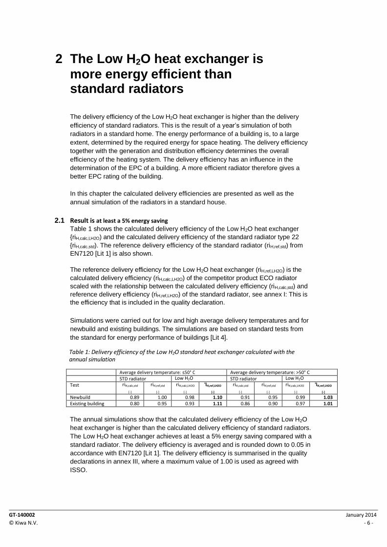
2.1 Result is at least a 5% energy saving
Table 1 shows the calculated delivery efficiency of the Low H2O heat exchanger
{riH,calc,LH2O) and the calculated delivery efficiency of the standard radiator type 22
{riH,calc,std). The reference delivery efficiency of the standard radiator (riH,ref,std) from
EN7120 [Lit 1] is also shown.
The reference delivery efficiency for the Low H2O heat exchanger (riH,ref,LH2O) is the
calculated delivery efficiency (riH,calc,LH2O) of the competitor product ECO radiator
scaled with the relationship between the calculated delivery efficiency (riH,calc,std) and
reference delivery efficiency (riH,ref,LH2O) of the standard radiator, see annex I: This is
the efficiency that is included in the quality declaration.
Simulations were carried out for low and high average delivery temperatures and for
newbuild and existing buildings. The simulations are based on standard tests from
the standard for energy performance of buildings [Lit 4].
Table 1: Delivery efficiency of the Low H2O standard heat exchanger calculated with the annual simulation
Average delivery temperature: ≤50° C Average delivery temperature: >50° C
STD radiator Low H2O STD radiator Low H2O
Test riH,calc,std
[-]
riH,ref,std
[-]
riH,calc,LH2O
[-]
'lH,ref,LH2O
[-]
riH,calc,std
[-]
riH,ref,std
[-]
riH,calc,LH2O
[-]
'lH,ref,LH2O
[-]
Newbuild 0.89 1.00 0.98 1.10 0.91 0.95 0.99 1.03
Existing building 0.80 0.95 0.93 1.11 0.86 0.90 0.97 1.01
The annual simulations show that the calculated delivery efficiency of the Low H2O
heat exchanger is higher than the calculated delivery efficiency of standard radiators.
The Low H2O heat exchanger achieves at least a 5% energy saving compared with a
standard radiator. The delivery efficiency is averaged and is rounded down to 0.05 in
accordance with EN7120 [Lit 1]. The delivery efficiency is summarised in the quality
declarations in annex III, where a maximum value of 1.00 is used as agreed with
ISSO.

GT-140002
© Kiwa N.V.
January 2014
- 7 -
2.2 The delivery efficiency is determined using an annual simulation of the Low H2O heat exchanger in a standard house Kiwa Technology has proven the energy saving of the Low H2O heat exchanger with
the help of the software package Matlab/Simulink. A standard home was simulated
[Lit 1] containing a standard parallel radiator or a Low H2O heat exchanger.
In Chapter 2.2.1 there is a description of the general simulation model. Then in
chapter 2.2.2 the Low H2O heat exchanger model is described which is contained
within.
2.2.1 The simulation is modular
The modular structure of the model is shown schematically in Figure 4. It consists of
three levels.
Figure 4: Structure of the simulation model to determine the performance of the Low H2O standard heat exchanger and standard radiator
At the top level external conditions are configured, including internal heat, heat
emission, ventilation, climate and sun, these are then presented to the subsystems
'building subsystem' and 'radiator subsystem'. The second level concerns the
'building subsystem'. This subsystem contains the model of a standard room and is
based on EN7120 [Lit 1]. The third level contains a detailed simulation of a standard
or a Low H2O heat exchanger. The theoretical model of the Low H2O heat exchanger
is validated on the basis of a practical measurement by Jaga-Konvekto according to
EN442, [Lit 6]. The complete model is validated according to EN15265 [Lit 4] by
calculating a number of cases, in which a standard radiator is used.
2.2.2 Modelling of the Jaga Low H2O
The Jaga Low H2O heat exchanger with the associated heat transfer mechanisms, is
shown in figure 5. In the middle of the figure there is the heat exchanger, including
enclosure and insulation, seen mounted on the wall. The heat exchanger radiates to
the enclosure and the insulation on the wall. The warm air carries heat to the enclosure
and the insulation on the wall by forced convection. The wall carries heat to the outside
air by radiation and free convection. The enclosure also carries heat to the air in the
room by radiation and free convection. The heat transfer at the wall and enclosure are
magnified on the sides.
Thermostat Sun Climate Ventilation Heat emission Internal heat
Radiator subsystem LH2O or standard
Simulation (verified according to EN15265 with standard radiator)
Building subsystem

GT-140002
© Kiwa N.V.
January 2014
- 8 -
Figure 5: Jaga Low H2O heat exchanger with heat transfer mechanisms
The elaboration of this model is shown in annex II.
Insulation
Wall
Enclosure
Heat exchanger

GT-140002
© Kiwa N.V.
January 2014
- 9 -
Literature list
Lit 1 NEN 7120:2011, Energy performance of buildings – Determination method
Lit 2 NEN-EN 15316-2-1:2007, Heating systems in buildings - method of calculating the energy requirement and the system efficiency - Part 2-1: Delivery systems for space heating
Lit 3 NEN-EN-ISO 13790:2008, Energy performance of buildings - Calculation of energy use for space heating and cooling
Lit 4 NEN-EN 15265:2007, Energy performance of buildings - Calculation of energy needs for space heating and cooling using dynamic methods - General criteria and validation procedures
Lit 5 NEN-EN-ISO 6946:1997, Components and elements of buildings – thermal resistance and thermal transmittance – determination method (ISO 6946:1996)
Lit 6 NEN-EN 442-2:1996, Radiators and convectors - test methods and presentation of the performance
Lit 7 polytechnic notebook G1/9, 48th
Edition, Royal PBNA, 1998)
GT-140002
© Kiwa N.V.
January 2014
- 10 -
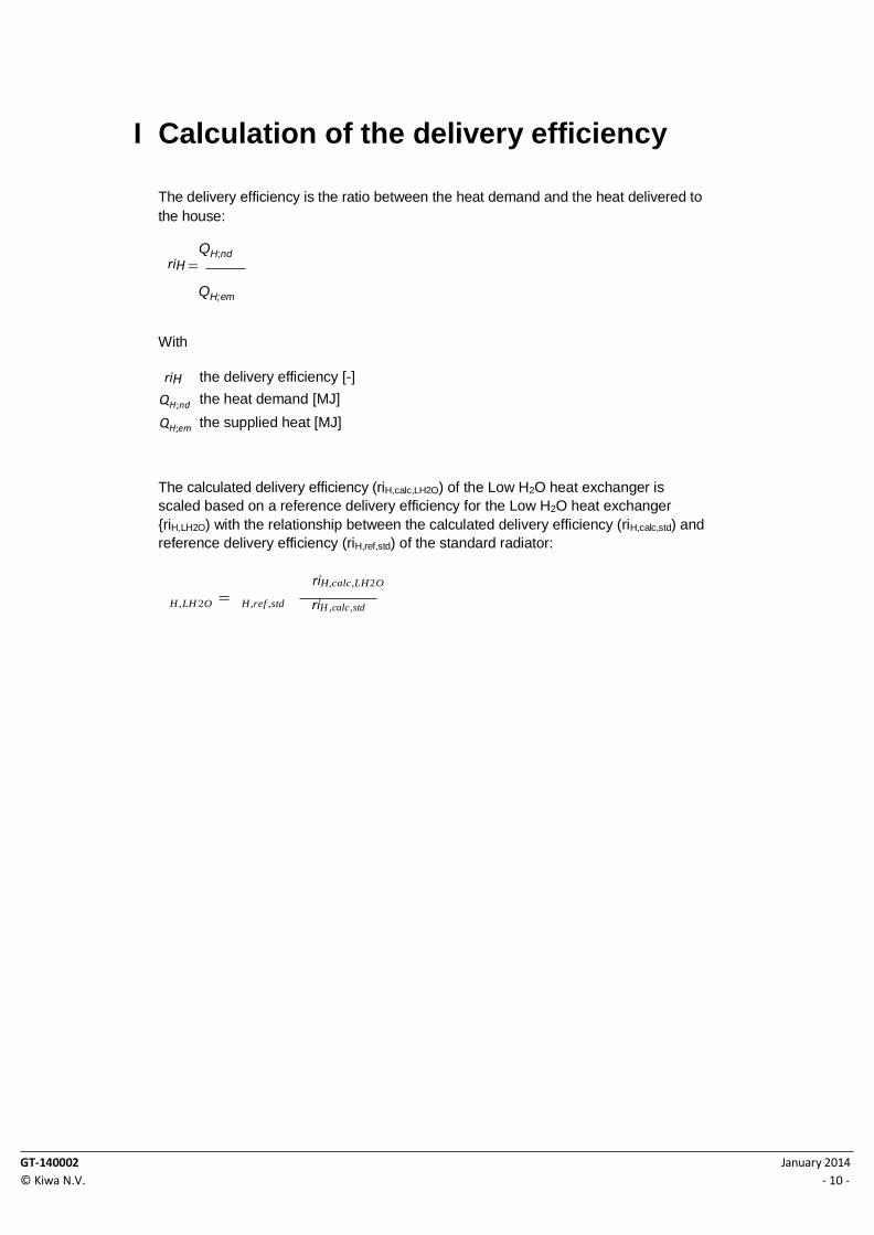
I Calculation of the delivery efficiency
The delivery efficiency is the ratio between the heat demand and the heat delivered to
the house:
QH;nd
riH QH;em
With
riH
QH;nd
QH;em
the delivery efficiency [-]
the heat demand [MJ]
the supplied heat [MJ]
The calculated delivery efficiency (riH,calc,LH2O) of the Low H2O heat exchanger is
scaled based on a reference delivery efficiency for the Low H2O heat exchanger
{riH,LH2O) with the relationship between the calculated delivery efficiency (riH,calc,std) and
reference delivery efficiency (riH,ref,std) of the standard radiator:
H , LH 2O H ,ref ,std
riH ,calc,LH 2O
riH ,calc,std

GT-140002
© Kiwa N.V.
January 2014
- 11 -
II Modelling of the Jaga Low H2O heat exchanger
The Jaga Low H2O heat exchanger with the associated heat transfer mechanisms, is
shown in Figure 5. In Figure 6 the Jaga Low H2O heat exchanger is shown in a lumped
capacitance scheme.
Figure 6: Lumped capacitance scheme of the Jaga Low H2O heat exchanger
This scheme consists of five known parameters and 20 unknown parameters, see Table
2. The 20 unknown parameters are to be solved using the equations from Table 2
that in are worked out in Table 3.
Known parameters Unknown parameters Comparison
T exchanger T air T outside T room Q in
T inside wall T outside wall T enclosure inside T enclosure outside T air out Q1 Q2 Q3 Q4 Q5 Q6 Q7 Q8 Q9 Q10
Q11
Heat transfer Q1 Heat transfer Q2 Heat transfer Q3 Heat transfer Q4 Heat transfer Q5 Heat transfer Q6 Heat transfer Q7 Heat transfer Q8 Heat transfer Q9 Heat transfer Q10
Law of conservation of energy (thermal pull) Law conservation of energy (system limits) Energy balance node A
Energy balance node B Energy balance node C Energy balance node D
T exchanger
Radiation (Q5)
T outside Conduction (Q2)
T wall inside
Convection (Q7) T air
T enclosure inside
T enclosure outside
Radiation (Q1)
Conduction (Q8)
Air which is flowing out on the top of the enclosure (Q11) T air out
T room
Radiation (Q9)
Radiation (Q3)
Convection (Q10)
Convection (Q4) Convection (Q6)
T wall outside

GT-140002
© Kiwa N.V.
January 2014
- 12 -
Q12 Energy balance node E
Q13 Energy balance node F
Q14 Energy balance node G
Q15 Energy balance node H
Table 2: Model parameters and equations
Q1 Radiation from the exchanger to the enclosure
The radiation is calculated by: Q =A·F·L·f3·(T 4-T 4)
rad exch wall
with
A = [m2] surface (top of the exchanger) F = [-] view factor L = [-] emission factor f3 = 5.67·10-8 [W/(m2·K4)] Boltzmann constant Texch = [K] temperature of the exchanger Twall = [K] temperature of the wall
Q2 conduction through the wall
The heat transfer is calculated using the equation for heat transfer by conduction.
Q = k/l·A·T [W] heat transfer
k = [W/(m·K)] thermal conductivity coefficient l = [m] wall thickness
A = [m2] area of the wall above the exchanger within the enclosure
T = Twall inside -Twall outside [K]
Q3 Radiation from the outer wall to the outside
See equations Q1
Q4 Convection from the outer wall to the outside
The heat transfer is calculated using the equation for heat transfer by free convection along a vertical wall.
Q = h·A·T [W] heat transfer
h = Nux·k/l [W/(m2·K)]
A = [m2] surface of the wall
T = Twall outside -Toutside[K] Nux = 0.671*(Pr/(Pr+0.986·Pr(1/2)+0.492))(1/4)·Ra(1/4)
Ra = (g·f3)/(a·v) ·l3T [-] Rayleigh number (g·f3)/(a·v) = air property
Q5 Radiation of the exchanger to the enclosure
See equations Q1
Q6 Convection to the inner wall
GT-140002
© Kiwa N.V.
January 2014
- 13 -
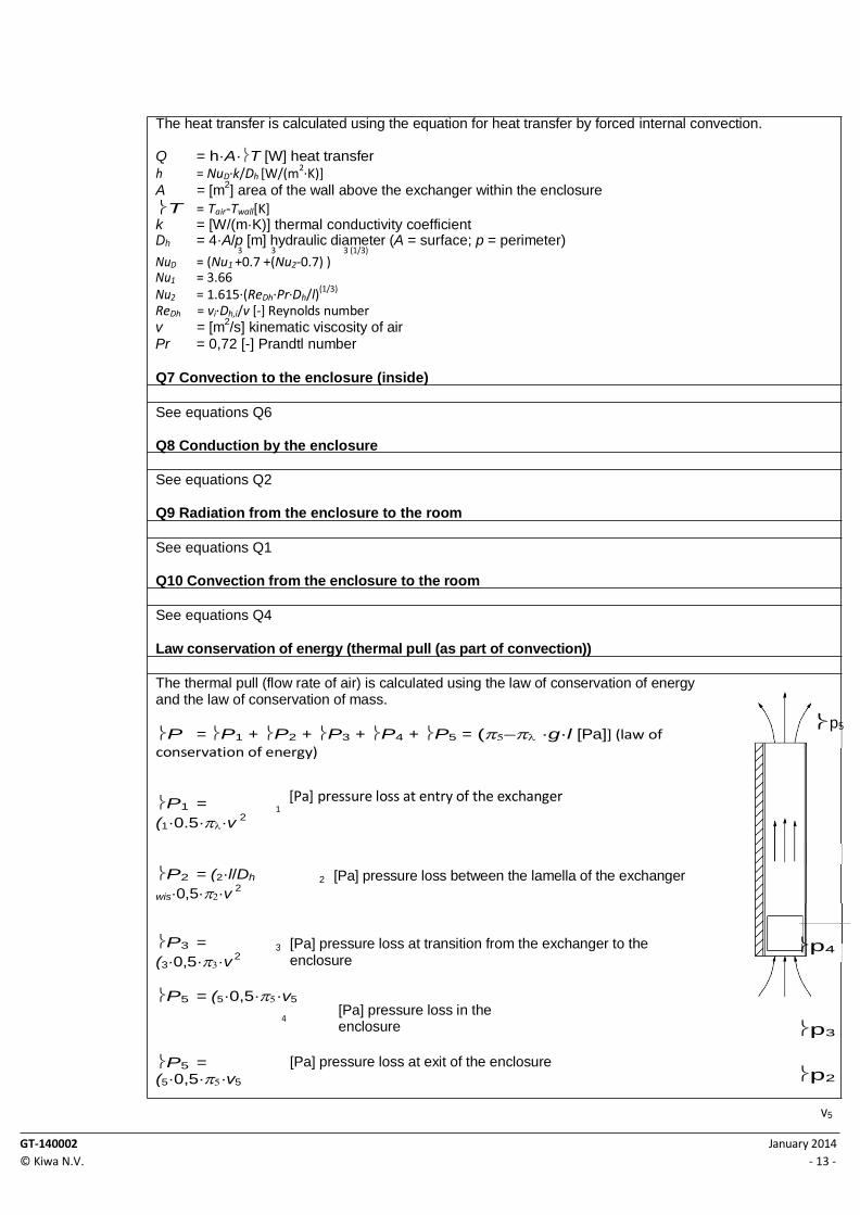
1
2
3
The heat transfer is calculated using the equation for heat transfer by forced internal convection.
Q = h·A·T [W] heat transfer
h = NuD·k/Dh [W/(m2·K)] A = [m
2] area of the wall above the exchanger within the enclosure
T = Tair-Twall[K] k = [W/(m·K)] thermal conductivity coefficient Dh = 4·A/p [m] hydraulic diameter (A = surface; p = perimeter)
3 3 3 (1/3)
NuD = (Nu1 +0.7 +(Nu2-0.7) ) Nu1 = 3.66
Nu2 = 1.615·(ReDh·Pr·Dh/l)(1/3)
ReDh = vi·Dh,i/v [-] Reynolds number v = [m
2/s] kinematic viscosity of air
Pr = 0,72 [-] Prandtl number
Q7 Convection to the enclosure (inside)
See equations Q6
Q8 Conduction by the enclosure
See equations Q2
Q9 Radiation from the enclosure to the room
See equations Q1
Q10 Convection from the enclosure to the room
See equations Q4
Law conservation of energy (thermal pull (as part of convection))
The thermal pull (flow rate of air) is calculated using the law of conservation of energy and the law of conservation of mass.
P = P1 + P2 + P3 + P4 + P5 = (·g·l [Pa]] (law of conservation of energy)
p5
P1 =
(1·0.5··v 2
[Pa] pressure loss at entry of the exchanger
P2 = (2·l/Dh
wis·0,5··v 2
[Pa] pressure loss between the lamella of the exchanger
P3 =
(3·0,5··v 2
[Pa] pressure loss at transition from the exchanger to the enclosure
p4
P5 = (5·0,5··v5
4
[Pa] pressure loss in the enclosure
p3
P5 = (5·0,5··v5
[Pa] pressure loss at exit of the enclosure p2
v5

GT-140002
© Kiwa N.V.
January 2014
- 14 -
= v4·= v3·= v2·= v1·m/s] (law of conservation of mass)
with
g = 9.81 [m/s2] gravitational acceleration
l = [m] height of the lamella
= [kg/m3] density of air
vi = [m/s] air speed (1 = 1 [-] friction factor
(2 = 4·24/ReDh [-] friction factor
p1

GT-140002
© Kiwa N.V.
January 2014
- 15 -
(3 = 1 [-] friction factor (4 = 4·24/ReDh [-] friction factor (5 = 1 [-] friction factor Dh = 4*A/p [m] hydraulic diameter (A = surface; p = perimeter) ReDh = vi·Dh,i/v [-] Reynolds number v = [m2/s] kinematic viscosity of air
The heat transfer is calculated using the equation for heat transfer by forced convection.
Q = ·A·T [W]
heat transfer with = 0.664·Pr1/3·Re1/2 [W/(m2·K)] Nusselt number A = [m2] projected surface of the exchanger on the wall Pr = 0,72 [-] Prandtl number
Law conservation of energy (system limits)
Qin=Q12+Q13=Q14+Q15+Q11
Energy balance node A
Q12=Q1+Q5
Energy balance node B
Q1+Q6=Q2
Energy balance node C
Q2=Q3+Q4
Energy balance node D
Q3+Q4=Q14
Energy balance node E
Q13=Q6+Q7+Q11
Energy balance node F
Q5+Q7=Q8
Energy balance node G
Q8=Q9+Q10
Energy balance node H
Q9+Q10=Q15

GT-140002
© Kiwa N.V.
January 2014
- 16 -
III Quality declaration: delivery efficiency 'lH,em of Jaga Low H2O heat
exchanger in a Tempo enclosure
Individual heating or district heating with individual metering. Height in computation
zone space of up to 8m.
Heat delivery type of heating system Average delivery
temperature
≤50ºC >50ºC
2a) Radiator heating and/or convector heating for outside
wall d; average thermal resistance of the external partition
elements e at the location of the radiators or convectors, Rc in
m2K/W, equal to or larger than 2.5
1.00
1.00
2b) Radiator heating and/or convector heating for outside
wall d; average thermal resistance of the external partition
elements e at the location of the radiators or convectors, Rc in
m2K/W, less than 2.5
1.00
1.00

GT-140002
© Kiwa N.V.
January 2014
- 17 -