deliverable-5.3 - proof of concept of dif management system · ericsson ltd., nextworks s.r.l.,...
TRANSCRIPT

Deliverable-5.3Proof of concept of DIF Management System
Deliverable Editor: Micheal Crotty, TSSG
Publication date: 30-April-2015Deliverable Nature: ReportDissemination level(Confidentiality):
PU (Public)
Project acronym: PRISTINEProject full title: PRogrammability In RINA for European Supremacy of
virTualIsed NEtworksWebsite: www.ict-pristine.euKeywords: DIF, management, system, RIB, proof-of-conceptSynopsis: This document describes the proof of concept of DIF
Management System for the first iteration of PRISTINEDMS. This proof of concept covers design andimplementation aspects of the DMS Manager, requiredRINA policies and interaction with the ManagementAgent. It also presents a brief overview of how to writePRISTINE specific management strategies.
The research leading to these results has received funding from the European Community's Seventh FrameworkProgramme for research, technological development and demonstration under Grant Agreement No. 619305.
Ref. Ares(2015)3645348 - 04/09/2015

Deliverable-5.3
2
Copyright © 2014-2016 PRISTINE consortium, (Waterford Institute of Technology, Fundacio Privadai2CAT - Internet i Innovacio Digital a Catalunya, Telefonica Investigacion y Desarrollo SA, L.M.Ericsson Ltd., Nextworks s.r.l., Thales Research and Technology UK Limited, Nexedi S.A., BerlinInstitute for Software Defined Networking GmbH, ATOS Spain S.A., Juniper Networks Ireland Limited,Universitetet i Oslo, Vysoke ucenu technicke v Brne, Institut Mines-Telecom, Center for Research andTelecommunication Experimentation for Networked Communities, iMinds VZW.)
List of Contributors
Deliverable Editor: Micheal Crotty, TSSGTSSG: Jason Barroni2CAT: Bernat GastonNXW: Vincenzo MaffioneATOS: Miguel Angel PuenteBISDN: Marc SuneLMI: Sven van der Meer
Disclaimer
This document contains material, which is the copyright of certainPRISTINE consortium parties, and may not be reproduced or copiedwithout permission.
The commercial use of any information contained in this document mayrequire a license from the proprietor of that information.
Neither the PRISTINE consortium as a whole, nor a certain party of thePRISTINE consortium warrant that the information contained in thisdocument is capable of use, or that use of the information is free fromrisk, and accept no liability for loss or damage suffered by any personusing this information.

Deliverable-5.3
3
Executive SummaryThis deliverable describes the proof of concept of DIF ManagementSystem for the first iteration of PRISTINE DIF Management System(DMS). Specifically, it contains the design of the DMS manager anddocuments its current implementation.
It begins with a general introduction to OSI management, the DMS andsome realistic deployment options and migration strategies.
The next section describes the DMS Manager in greater detail. It outlinesbest practices for modular software design and presents a layered designthat allows deployment (and technology) flexibility. This is followed by adetailed description of the components that form each layer in the DMS.
This is followed by a worked example of writing a "management strategy".This details the java interfaces to use, and how implementations of theseinterfaces may be combined to provide desired results.
An update on the current design of the Management Agent (MA) isthen presented. It outlines the improvements and the trade-offs ofimplementing the design. This is followed by the current implementationstatus and a benchmark against the requirements defined in earlierdeliverables.
The validation section attempts to document the "validation" environment.It outlines the default (RINA) policy set that is required in the IRATI stack,the validation scenario with three nodes and the management strategiesrequired to support the validation.
The final section attempts to summarise the work left to be done. Formanager and management agent, additional implementation work isneeded to support the monitoring scenarios as defined in [D52]. Thisincludes the next steps to be undertaken and the (RINA) stack policies thatwill need to be implemented. The Manager also has some additional workneeded to support a more complete (RINA) stack integration.
Deliverable-5.3
4
Table of ContentsList of acronyms ........................................................................................................ 71. Introduction ............................................................................................................ 8
1.1. Scope ............................................................................................................... 81.2. Classic Management Paradigm .............................................................. 81.3. PRISTINE DIF Management System ................................................... 91.4. Deployment Options and Migration Strategies ............................... 121.5. Community-driven Management Strategies .................................... 14
2. DMS Manager ...................................................................................................... 162.1. Layered, Modular Platform Design ..................................................... 172.2. Layered, Modular Implementation Design ...................................... 192.3. Layered, Modular Implementation Packages .................................. 192.4. DMS Manager Architecture .................................................................. 212.5. Detailed Description – 2-ES ................................................................. 242.6. Detailed Description – 2-ES-WS ......................................................... 412.7. Detailed Description – 2-ES-ZK ......................................................... 422.8. Detailed Description – 2-ES-WS-ZK ................................................. 432.9. Detailed Description – 3-ES-DSLs ..................................................... 442.10. Detailed Description – 3-Strategies ................................................. 482.11. Detailed Description – 3-RIB .............................................................. 512.12. Detailed Description – 4-Manager ................................................... 532.13. External Dependencies ......................................................................... 55
3. Strategy design .................................................................................................... 583.1. Writing Strategy Logic ........................................................................... 583.2. Assemble a Strategy ................................................................................ 623.3. Implement a Strategy Trigger ............................................................. 623.4. Deploy and Activate a Strategy ........................................................... 63
4. Agent design ........................................................................................................ 654.1. Architecture updates ............................................................................... 654.2. Low level implementation .................................................................... 674.3. State of the implementation ................................................................ 70
5. Validation .............................................................................................................. 745.1. Default policy set ...................................................................................... 745.2. Three node validation scenario ........................................................... 755.3. Strategies used for validation ............................................................... 76
6. Future plans ......................................................................................................... 786.1. Monitoring ................................................................................................. 78

Deliverable-5.3
5
6.2. Management Agent and RINA stack ................................................. 806.3. DMS Manager .......................................................................................... 80
References ................................................................................................................. 82

Deliverable-5.3
6
List of Figures
1. Manager Agent Paradigm ................................................................................... 92. DMS Paradigm .................................................................................................... 103. Deployment Option 1 ........................................................................................ 124. Deployment Option 2 ....................................................................................... 135. Layered, Modular Platform Design ............................................................... 186. Layered, Modular Implementation Packages ............................................ 207. DMS Manager Software Architecture .......................................................... 228. DMS Implementation: Architecture View .................................................. 239. DMS Architecture Package and Dependency View .................................. 2410. ES Taxonomy and ES Event Architecture View ..................................... 2511. ES Taxonomy and ES Event Composition View ..................................... 2512. DSL Framework Architecture View ............................................................ 2813. DSL Framework Composition View ........................................................... 2814. ES Services Architecture View ...................................................................... 3415. ES Service Connectors Composition View ............................................... 3516. Event Visualiser with Offline Event Stream ............................................. 3717. Generic State Machine Classes ..................................................................... 3818. ES Tools .............................................................................................................. 3919. ES Backend with Service Execution and Standard CLI ........................ 4020. ES Websocket Connectors ............................................................................. 4121. ES Zookeeper Connector ............................................................................... 4222. ES Websocket-Zookeeper Connectors ...................................................... 4323. DMS DSLs Architecture View ...................................................................... 4424. DMS DSLs Implementation View ............................................................... 4425. Trigger DSL implementation ....................................................................... 4726. Strategies Software Architecture ................................................................. 4927. Strategies Dependencies ................................................................................ 5028. DMS 4-Manager packages and dependencies .......................................... 5429. DMS 4-Manager application architecture ................................................. 5530. DMS 4-Manager application packages ...................................................... 5531. Management Agent architecture ................................................................. 6632. DMS validation scenario ................................................................................ 75

Deliverable-5.3
7
List of acronyms3PP Third Party Provider
AMQP Advanced Message Queuing Protocol
CACE Common Application Connection Establishment
CDAP Common Distributed Application Protocol
CLI Command Line Interface
DAF Distributed Application Facility
DAP Distributed Application Process
DIF Distributed-IPC-Facility
DMS Distributed Management System
DSL Domain Specific Language
DTCP Data Transfer and Control Protocol
EFCP Error and Flow Control Protocol
ES Event System
FCAPS Fault, Configuration, Accounting, Performance and Security
IPC Inter-Process Communication
IPCP Inter-Process Communication Process
IPCM Inter-Process Communication Manager
NM Network Management
NMS Network Management Service
OODA Observe, Orient, Decide, and Act
OSS Operation Support System
PDU Protocol Data Unit
RIB Resource Information Base
RINA Recursive Inter-Network Architecture
SDU Service Data Unit
VLAN Virtual LAN
VM Virtual Machine
Deliverable-5.3
8
1. Introduction
RINA is proposed as a clean state network architecture designed specificallyto tackle the complexity inherent in many of todays' networks. TheRecursive Inter-Network Architecture (RINA) is an emerging clean-slate programmable networking approach, centring on the Inter-ProcessCommunication (IPC) paradigm, which will support high scalability,multi-homing, built-in security, seamless access to real-time informationand operation in dynamic environments. The heart of this networkingstructure is naturally formed and organised by blocks of containerscalled “Distributed Information Facilities - DIFs” where each block hasprogrammable functions to be attributed to as required. A DIF is seen as anorganising structure, grouping together application processes that provideIPC services and are configured under the same policies.
1.1. Scope
This deliverable focuses specifically on the work conducted to implementa proof of concept DIF management system. The DIF Management systemfollows an OSI (manager/agent) model. The first sections describe thedesign and implementation details of the DMS Manager componentsas it currently stands. A key feature of the DMS manager is theflexibility it offers in specifying management strategies. For example,for network configuration it allows a set of management strategies todefine a declarative contract based specification for a DIF and providesa mechanism to verify DIF configuration via the RIB. The currentimplementation status of the management agent parts is also included.
1.2. Classic Management Paradigm
The classic management paradigm, often referred to as Manager-AgentParadigm, builds a management system out of Managers and Agentssupported by Managed Objects (MO) and Management Information Bases(MIB). A manager realises management functionality, in classic termsgrouped functionally as fault, configuration, performance, accountingand security management (also called the FCAPS). An agent controlsreal resources, which can either be physical (network nodes, e.g.switches, routers) or logical (e.g. elements of a protocol stack or othernon-physical artefacts). To simplify management instrumentation, an
Deliverable-5.3
9
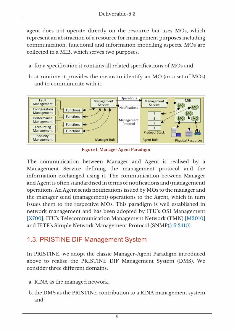
agent does not operate directly on the resource but uses MOs, whichrepresent an abstraction of a resource for management purposes includingcommunication, functional and information modelling aspects. MOs arecollected in a MIB, which serves two purposes:
a. for a specification it contains all related specifications of MOs and
b. at runtime it provides the means to identify an MO (or a set of MOs)and to communicate with it.
Manager Role
FaultManagement
PerformanceManagement
ConfigurationManagement
AccountingManagement
SecurityManagement
Functions
Functions
Functions
Functions
Agent Role
Protocol Stack
MIB
Physical Resources
MOMO
1234
MOMOMO
ManagementProtocol
Operations
Notifications
ManagementService
ManagementService
Figure 1. Manager Agent Paradigm
The communication between Manager and Agent is realised by aManagement Service defining the management protocol and theinformation exchanged using it. The communication between Managerand Agent is often standardised in terms of notifications and (management)operations. An Agent sends notifications issued by MOs to the manager andthe manager send (management) operations to the Agent, which in turnissues them to the respective MOs. This paradigm is well established innetwork management and has been adopted by ITU’s OSI Management[X700], ITU’s Telecommunication Management Network (TMN) [M3010]and IETF’s Simple Network Management Protocol (SNMP)[rfc3410].
1.3. PRISTINE DIF Management System
In PRISTINE, we adopt the classic Manager-Agent Paradigm introducedabove to realise the PRISTINE DIF Management System (DMS). Weconsider three different domains:
a. RINA as the managed network,
b. the DMS as the PRISTINE contribution to a RINA management systemand

Deliverable-5.3
10
c. an outside domain to demonstrate how other systems (e.g. legacymanagement systems, vendor-specific solutions) can be connected tothe DMS.
The main purpose of this document is to describe the DMS, followed byhow it integrates with RINA and finalised by a discussion on how externalsystems can be connected to the DMS.
RINAPRISTINE DMS
MgmtAgent(MA)
ManagerManagedResource
(RINA)
others API Calls, etc.
Human
NMS
BSS/OSSCDAP
Outside PRISTINE
Figure 2. DMS Paradigm
In the PRISTINE DMS, the Agent is closely related to RINA. Here, wedo not use any of the standardised MIBs to control MOs as such but theRINA Resource Information Base (RIB) and the resource object it contains.Thus, the DMS Management Agent (MA) maintains a RIB of the partsof a RINA network it controls. Communication between the MA and theRINA network is realised by the Common Distributed Application Protocol(CDAP), which is part of the RINA specification. CDAP provides all meansto realise the Manager-Agent communication in a RINA-specific way, sothere is no need to define a separate management protocol for the DMS.
The information exchanged between the DMS Manager and the MA is alsobased in the RINA RIB. The notifications the MA can send are defined in theRIB. Management operations the Manager can issue are the CDAP definedoperations executed on RIB objects. CDAP provides for six operations:create, delete, start, stop, read and write. Thus the manager is able to createand delete RIB objects, read and alter information, and also start and stopthem. These operations can be issued on a single RIB object for simplemanagement or in a transaction covering multiple RIB objects for morecomplex management operations.
The manager can realise any management function (as per the introducedFCAPS but also additional functions if required) by decomposing acomplex management function into one or more CDAP operations onspecific RIB objects. This eliminates the need for a more complexcommunication interface, as can be found in other management

Deliverable-5.3
11
approaches and systems. In turn, this allows for a rather simplemanagement middleware covering the basic communication (CDAP),functional (FCAPS) and information modelling (RIB) aspects of the RIB.Furthermore, the RINA Distributed IPC Facility (DIF) concept alreadyimplements a full domain model for management of flows with a particularDIF. This means that even the (management) domain model of theDMS can be inherited from RINA, including the addressing of any RINAresource.
The primary activity of the DMS can now be described as follows:a RINA system uses policies to configure the behaviours of a DIFand its components. The policies and the related resources aremodelled in the RIB. The DMS MA provides access the RIB for theDMS Manager, which in turn uses management strategies to realisespecific management functionality. We are using the term “managementstrategies” to distinguish DMS management from RINA control policies.In classic management terminology the DMS management strategiesare management policies. In other words, the DMS manager maintainsstrategies and configuration templates, uses them to issue operationson RIB objects via the MA. In turn, the MA monitors RIB objects andissues notifications to the DMS Manager, triggering the strategies and theevaluation of configuration profiles.
This drastically simplified management middleware allows DMS usersto focus on the actual management functionality expressed in DMSstrategies. In RINA terms there are four different management points tobe considered:
a. managing the underlying Operating System (OS-DMS),
b. managing a particular DIF (NM-DMS),
c. managing a collection of DIFs (AM-DMS) and finally
d. managing a RINA name space (NSM-DMS).
The DMS can provide for a standard set of strategies for each of thesemanagement points while allowing a DMS user to customise and/or extendthis set. The required instrumentation for these tasks is built into theDMS middleware. The result is a simple, distributed, yet very powerfulmanagement solution based on RINA principles and standards ready tomanage RINA networks.

Deliverable-5.3
12
1.4. Deployment Options and Migration Strategies
The PRISTINE DMS has been built to accommodate several deploymentoptions and migration strategies. This includes mechanisms to connectoutside systems, e.g. legacy systems such an existing Operation SupportSystem (OSS) or an existing Network Management system (NMS), to theDMS. To be RINA compliant, the DMS will need to use the CommonApplication Connection Establishment (CACE) with an appropriatecommunication module. This CACE can then be mapped to CDAP (fornative RINA communication) or to any other protocol effectively wrappingthis very protocol – e.g. HTTP – with CDAP. The DMS is built to supporta CACE using any communication protocol, ideally CDAP. This allows formultiple deployment options and migration strategies.
The starting point here is the DMS MA which is developed to communicatewith a RINA network using CDAP and offers a CDAP interface for the DMSManager. However, an initial deployment as well as the initial developmentof the DMS Manager might not (quite often cannot) enjoy a full CDAPimplementation. For those deployments, the DMS has developed a CDAPconnector which translates CDAP messages from and to the MA intoany DMS specific communication protocol realised by a DMS MessagingSystem (DMS-MS).
Manager MgmtAgent(MA)
CDAPConnect
ManagedResource
(RINA)
API Calls, etc.CDAP
ManagerApp
ManagerApp
ManagerApp
MessagingSystem
MgmtShell / GUI
MgmtShell / GUI
MgmtShell / GUI Other
AppsOtherApps
OtherApps
Figure 3. Deployment Option 1
This DMS-MS can use any underlying communication protocol andmessage encoding, as long as the actual messages are a direct representation(syntactical and semantical equivalent) to the original CDAP messages

Deliverable-5.3
13
the MA understands. This allows management applications (distributedDMS managers), Command-Line Interfaces (CLI, e.g. management shells),Graphical User Interfaces (GUI, e.g. in a web browser using HTML5) andother applications to build the above introduced management strategiesoperating on RIB objects using the defined CDAP operations. On theother hand, this allows deployment options that can use (for multiplereasons) any underlying communication protocol and concrete messagingencoding.
In the example of the developed DMS, we are using a W3C Websocket[rfc6455] implementation for communication and a JSON schema [json-s] for message encoding. The CDAP Connector simply receives a JSONmessage on a Websocket and directly translates it into a CDAP protocol unitsent to the MA. Vice versa, the CDAP Connector receives CDAP protocolunits from the MA and directly translates them into JSON encodedWebsocket protocol units.
In case where a native CDAP implementation is available to the DMSManager, the deployment option changes. Now, the DMS Managercomponents (manager applications, CLI, GUI, other applications) candirectly use CDAP to communicate with the MA, eliminating the use of theCDAP Connector.
Manager MgmtAgent(MA)
ManagedResource
(RINA)
API Calls, etc.
ManagerApp
ManagerApp
ManagerApp
MgmtShell / GUI
MgmtShell / GUI
MgmtShell / GUI
OtherApps
OtherApps
OtherApps
MessagingSystem
OtherApps
OtherApps
OtherApps Mgmt
Shell / GUI
MgmtShell / GUI
MgmtShell / GUI
CDAPFlows
Figure 4. Deployment Option 2
However, legacy applications can still be connected to the DMS Managerusing the already implemented DMS-MS. Several intermediate stepsbetween the first deployment option (using a CDAP connector) and the

Deliverable-5.3
14
second deployment option (using a native CDAP implementation and amessaging system for external components) are possible. These can be usedto define and execute a migration strategy for the DMS Manager.
These migration strategies are directly supported by the current DMSimplementation. The DMS design (and the actual implementation) realisea simple interface for management applications to manipulate RIB objects,regardless of the underlying protocol, be that a combination of Websocket/JSON, native CDAP or something else. For each selected deploymentoption and identified migration strategy, the only requirement is to linkthe DMS Manager applications to a version of the DMS implementationsupporting the required communication stack. No change in the developedmanagement functions or applications is required. Designed this way, theDMS can support virtually any deployment option and migration strategyin a future-proof way.
1.5. Community-driven Management Strategies
Managing the details of a RINA network can require a significantunderstanding of the underlying design principles, the RINA standards (e.g.for DIFs, CDAP, Naming and Address Architecture) and particular RINAimplementations (e.g. the IRATI RINA implementation). The impliedlearning curve can impede an uptake of RINA as an alternative networkingarchitecture especially because the management of a RINA network is afundamental task for its successful operation. While the DMS is designedand built to support flexible management, not all RINA users will be willingto or able to develop their own management strategies.
The DMS addresses this issue by facilitating an active exchange ofDMS Management Strategies among RINA users and of course amongmanagers of RINA networks. First, the DMS platform described in thisdocument provides a generic state machine that in turn allows buildingmanagement strategies in many different flavours. We provide an OODAbased strategy implementation, but one can easily use action policies (orEvent-Condition-Action (ECA) policies), goal policies, utility functions oreven more advanced mechanisms such as Bayesian networks. The genericstate machine also allows using a combination of the above.
Second, this flexible mechanism to use virtually any implementationof a strategy (as long as it is using the provided generic state machine
Deliverable-5.3
15
as underlying execution environment) can be used to create a marketand exchange place for DMS Management Strategies. This market placecan supply standard strategies approved by RINA experts (or the PouzinSociety as the RINA guardian) as well as any strategy of any user, usergroup, organisation or company. The idea of this market place is verysimilar to the well-known app stores for mobile phone operating systemsand platforms.

Deliverable-5.3
16
2. DMS Manager
The platform for the DMS manager is designed to facilitate the flexibilitynecessary to manage a RINA deployment. The design decisions that guidedthe development of the DMS Manager are listed below.
First, all parts of the DMS Manager communicate by exchanging messages.This leads to an event-sourced [fowler05] design in which all interfaces aredefined by events. An event can be sent, received, manipulated, logged,stored and archived. Events that have been stored can be re-run in the DMSfor testing, debugging or demonstration purposes. Complete managementscenarios can be explored in any detail using those re-runs.
Second, the DMS platform is designed as a distributed managementsystem. A messaging system connects all DMS components. Any numberof components can be connected, limited only by performance andscale limitations of the actually used messaging system. Differentmessaging systems can be interconnected to join different worlds,for instance RINA CDAP with AMQP, distributed (hash-) maps andWebsockets. This allows for integration of enterprise messaging systems(AMQP) with web applications (Websocket) and RINA networks. Adistributed system requires configuration management for componentsand their connections. Currently, the platform uses Apache Zookeeper fordistributed configuration management. Zookeeper can be easily replacedby any other equivalent system.
Third, the DMS platform uses a layered design focusing on a modularimplementation. Layers define the platform’s functional areas. Modulesimplement a layer’s functionality or parts of it. Modules will have a direct,acyclic dependency graph from the top layer to the bottom layer realising acomplete deployable stack. Changing modules in the stack allows migratingfrom one deployment option to another. These changes can be done forall or only a few management applications at a time.
Fourth, the DMS platform is using a shared event taxonomy and a DomainSpecific Language (DSL) approach to define events. The event taxonomydefines all elements of a platform event. The DSL approach then allowsdefining complete event languages and dialects. The main DSL used inthe platform is a DSL realising CDAP. Other DLSs provided are for thecontrol of management applications and legacy integration as well as for

Deliverable-5.3
17
specific demonstrations. The DSL approach has built-in mechanisms forautomated translation between different DSLs and different DSL dialects.
Fifth, the DMS platform supports integration with legacy (management)systems. The combination of different messaging systems with theDSLs approach (automated translation) allows mapping communicationand information being translated automatically between very differenttechnology worlds.
Sixth, the DMS platform is designed to generate most runtime code fromspecifications. For instance, a DSL automatically provides an interface(Application Programming Interface – API) to create, send, receive andaccess events for that DSL. The connection to a particular messagingsystem only requires calling the respective module implementing theaccess point. Tools are provided for defining, maintaining, using the eventDSLs, including runtime tools for distributed logging, archiving and re-running event sets. All management applications using a defined eventDSL can use an automatically generated Command Line Interface (CLI) forcontrol. This CLI also allows for scripting single or complete managementand control tasks. This in turn allows a RINA system administrator touse their tool of choice (e.g. bash scripts, configuration profiles) to runotherwise tedious management tasks.
2.1. Layered, Modular Platform Design
The platform design comprises four layers each with well-defined scopeand interactions. The scope of the layers goes from platform generic(management application) down to runtime specific (runtime platform).Top layers use functionality from lower layers (without cross-layerinteractions). The use of functionality can be contractual and policycontrolled if required. Bottom layers provide functionality to higher layers.The provisioning of functionality can be done by an API, a library, aprotocol or a service access point, to name a few options.

Deliverable-5.3
18
Applications
Component Designand Implementation
Service Design andImplementation
Event-based Runtime
use
use
use
prov
ide
prov
ide
prov
ide
Runtime Platform
Configuration ManagementCDAP Node
CDAP Node
CDAP Node
CDAP NodeEvent Bus
SNMP Node
HTTP Node
CORBA Node
WS Node
Platform Services
Components
Domain / Set 3
Domain / Set 2
Domain / Set 1
ApplicationsScenarios &Use Cases
Scenario
Application
Use Case
Presentation Business Logic
Platform &Infrastructure
Runtime
Presentation-specific
Common to all
Presentations
Figure 5. Layered, Modular Platform Design
Layers classify the parts of the DMS platform and determine levelsof abstractions with four layers being identified: presentation (fordemonstrations, prototypes and management solutions), business logic(with two sub-layers), platform and infrastructure (for communication andcommon services), and runtime (for off-the-shelve, open source or 3rdparty runtime solutions).
The presentation layer provides a view for applications, scenarios and usecases. Specific requirements of those are defined and realised here. Theycan be developed in isolation or with stronger interactions. The main scopeof this layer is to present the applications usually to a human being.
The business logic layer provides for a component view. Its main scopeis to implement the required business logic for the presentation layerin form of components as the unit of deployment (deployable softwareartefacts). If required, it can be subdivided into a part focusing on specificlogic for specific presentations (called presentation-facing business logic)and a part focusing on more generic business logic supporting two ormore specific presentations (called common business logic). Business logiccomponents can be grouped in sets or domains supporting differentapplication deployment options and strategies.

Deliverable-5.3
19
The platform and infrastructure layer builds and deploys the actualdistributed platform using runtime services. Services can be groupedif required. This layer also needs to provide a means for distributedconfiguration management of the platform. Ideally it must allow foran automated deployment or at least for very flexible scripting of thedeployment, i.e. there should be no single deployment scenario beingmandated by this layer.
The runtime layer provides the runtime platform realising the DMSdistributed event system and the configuration management components.Here we find the off-the-shelve, open source, 3rd party or self-developedruntime components for the messaging system, all tools for DSLprocessing, component deployment and configuration management.
2.2. Layered, Modular Implementation Design
The design of the implementation directly follows the platform design.On the presentation layer we find the management demonstrations andapplications. The business logic layer is sub-divided as discussed above.The presentation-facing part builds the DMS Manager applications. Thecommon logic part builds the DMS Management Strategies (currentlyusing OODA state machine), the CDAP DSL and the managementapplication DSLs (for communicating with the manager) and a RIBimplementation supporting all management applications. The platformand infrastructure layer provides the messaging system (current) andCDAP (future) which is then realised by the runtime layer.
2.3. Layered, Modular Implementation Packages
The implementation of the DMS platform provides for a number ofmodules with a directed, acyclic dependency graph. The naming ofthe packages links them to the respective layer of the design. Packagesstarting with 5- are in the presentation layer. Packages starting with 4- arepresentation-facing business logic components. Packages starting with 3-are common business logic components. Finally, packages starting with 2-are platform and infrastructure components.

Deliverable-5.3
20
Runtime Platform
Platform Services
Components
ApplicationsScenarios &Use Cases
RINA System Runtime
CDAPImplementation
3-strategies-examples3-strategies
3-esdsls3-rib
5-demo
4-manager 2-esevent
system
Runtime Platform
Platform Services
Components
ApplicationsScenarios &Use Cases
W3C Websockets Apache Zookeeper
2-es-ws2-es-zk
2-es-zk-ws
3-strategies-examples3-strategies
3-esdsls3-rib
5-demo
4-manager 2-esevent
system
Figure 6. Layered, Modular Implementation Packages
The presentation layer has currently one implementation 5-Demo todemonstrate DMS Manager strategies. It will be extended in the PRISTINEproject with the implementations of the use cases. The business logic layercontains the manager (4-Manager) and several common components. 3-RIB implements a RIB view for the strategies. The package 3-EsDSLsdefines the event DSLs for the DMS, including the CDAP representation,a trigger language for simulating network events and the control languagefor managers and strategies. Based on those two, the package 3-Strategiesimplements the generic OODA strategy and all required tools to defineand deploy an OODA strategy. Finally, the package 3-Strategies-Examplesprovides a number of example and testing strategies. Beside the examples,all packages should require very little change once they mature.
For platform and infrastructure the DMS Manager package (4-Manager)can select between multiple options to use, each providing messagingsystems in different constellations. Ideally, the DMS platform shipswith a native CDAP implementation, as planned for the future. Asa starting point, the platform implements two different messagingpackages: 2-ES-WS and 2-ES-ZK-WS. The first realises a Websocketbased messaging system with manual configuration of connections. Here,a server component must be started and then all other componentsmust be manually connected to it (this can be scripted but the DMSplatform does not provide for further automated deployment). The secondone provides the same messaging connector (Websocket) but with anautomated configuration of connections using Apache Zookeeper. Fordeployment, one only needs to provide access to a Zookeeper clusterand the implementation will gather all other configuration automatically,including all client configuration. The package 2-ES-ZK implements the

Deliverable-5.3
21
required functionality to communicate with Zookeeper, including creationof ephemeral configuration objects and re-connectors for automated re-creation of connections in case of network (or Websocket) failure.
One package, uniquely, provides functionality across all platform layers:2-ES. This package implements the complete distributed event systemincluding the shared taxonomy, the used DSL framework, event andDSL APIs, messaging system connector interfaces, runtime tools andcomponents, automated generation of CLI and event processing. Inaddition, this package implements the generic state machine used bythe management strategies. Last but not least, the package provides acomplete visualisation framework for events using the event taxonomy.This visualisation framework is realised in HTML5 and can be run inany Websocket-enabled HTML5 web browser. The event visualizer canbe flexibly configured for online event viewing (live runtime events) orfor offline event analysis (including multiple options for visual eventcorrelation).
2.4. DMS Manager Architecture
This design guides in the DMS Manager software architecture. DMSapplications can run in any execution environment, e.g. inside anOpenStack compute node, in a Docker container or on a native operatingsystem. For communication, it can use multiple messaging systems, e.g.Websockets, AMQP messaging solutions or native CDAP. On top of thosemessaging systems, we build communication adaptors which simplify theconfiguration and usage of those messaging systems. This means that aDMS application does not need to be concerned with any details of themessaging system.

Deliverable-5.3
22
Applications
Application-specificBusiness Logic
Project CommonBusiness Logic
Event System (ES)and DSL Framework
ES-CommunicationAdapters
Off-the-shelveProducts
General Computing and Networking Infrastructure, e.g. OpenStack, Docker, Native OS
ES-specific Infrastructure, e.g. Message Bus, Zookeeper, CDAP, others
Zookeeper
WebsocketsCDAP Websockets
Common CatalogueBase System Event Taxonomy & ES Event Event Tools
DSL Framework ES Base Languages, e.g. Es Event Viz DSL Tools
Event System Services
RIB Strategy RuntimeProject-related DSLs Strategy Language & Compiler
DMS Manager
DMS Manager Demo••• Scenario or
Demo nScenario or
Demo 1
Figure 7. DMS Manager Software Architecture
The lowest level of abstraction is the DMS Event System (ES). It implementsthe base system (utility classes); the event taxonomy and the infrastructurefor creating, sending, receiving and decomposing events; standard eventtools and a common catalogue. The DSL framework allows for an easydefinition of events and their content for a particular domain 1. Thisincludes automated syntax and semantic checks and automated eventprocessing against a specified DSL. ES services then provide the simpleaccess to that functionality.
With this underlying infrastructure, the actual management system andits applications can focus on building their specific business logic. Incase of the DMS, this is a RIB view, management related DSLs, and animplementation of management strategies with related tools to create anddeploy them into a DSM. Finally, we can build any number of managementapplications, demonstrations or scenario specific solutions.
1In PRISTINE’s case, that domain is management of RINA DIFs, and DAFs.

Deliverable-5.3
23
Figure 8. DMS Implementation: Architecture View
The implementation architecture directly follows the described softwarearchitecture.

Deliverable-5.3
24
Figure 9. DMS Architecture Package and Dependency View
The introduced packages’ dependencies represent a directed, acyclic graph.The dependencies with weight factor are shown in Figure 9.
2.5. Detailed Description – 2-ES
This section details the underlying Event System (ES). Each part of thispackage is discussed in detail. Structure 101 [S101] is used to generate apackage architecture figure (with dependencies) and package compositionview(s) are provided to show how the different parts of this package linktogether.

Deliverable-5.3
25
2.5.1. ES Event Taxonomy and ES Event
Figure 10. ES Taxonomy and ES Event Architecture View
Figure 11. ES Taxonomy and ES Event Composition View
ES Taxonomy
The event taxonomy defines events exchanged between components. Inthe taxonomy, an event contains a fixed header part and a flexible payloadpart. The header is used to automatically process events, integrate themwith a DSL and route events in the messaging system.
An event header is defined by five primitives: type, source, language,dialect and version. The event type characterises an event and can be usedfor categorisation, for example using the FCAPS management functions.The event type is arbitrary but must be understood by sender and receiver.Standard event types can be found in the Event DSL described below.
The event source indicates the sender of an event. This can be done in moregeneric terms (e.g. categorising an application as OSS or NMS or Manageror MA) or in more specific terms (e.g. providing also an address or specific
Deliverable-5.3
26
name of the sender). The event source is arbitrary and can be specific toa given event DSL.
The event language specifies which event DSL being used for the payloadpart. This must be specified using the actual DSL identifier, it is notarbitrary. For automated event processing the language identifier is usedto request the DSL for syntax and semantic checks on incoming events orevents to be sent. It is also used in a similar way in the visualizer to processotherwise arbitrary events.
The event (language) dialect indicates a particular dialect of the eventlanguage used in the given event. This identifier must specify an existingdialect defined in the event DSL. It is then used to further refine theautomated event processing described above for the event language.
The event (language) version indicates a specific version of the event DSLthe event is using. This header primitive is introduced to simultaneouslysupport multiple versions of the same event DSL yet being able to monitorand debug the components of the system.
All header primitives are defined as interfaces (prefixed by TAX_) andsupported by a default implementation. Since they are standardised inthe event taxonomy, there should be little need to extend these defaultimplementations. However, for integrating the headers into a higher-levelconcept (such as the DSL framework), some minor specialisations mightbe necessary.
The event header also contains some primitives that are automaticallycompleted when an event is generated. They supply identifier and timeinformation. The identifier and a hash code for that identifier are createdusing an ES standard method 2. This ensures that all events have a uniqueidentifier. The second automatically generated primitive is a time stampfor event creation. The time will be stored as a Java epoch time usingthe standard second time scale and a time string which uses the followingformat: yyyy-MM-dd HH:mm:ss.SSS.
2The current standard method uses Java VM and process IDs for the generation. Other,non-Java based, methods could use for instance UUIDs or GUIDs for unique identifiers.

Deliverable-5.3
27
ES Event
The ES Event implements an event with header and content maps plustransformers. Both header and content map are key/value based hashmaps. The header map is immutable. The content map is mutable.
An event builder is provided to simplify event creation. It generates theevent header and initialises an event. The event builder is the only way tocreate events. It performs a complete validity check on all given input andonly creates an event if it is valid, i.e. it conforms to the event taxonomy.Otherwise no event is created.
Connecting event creation and processing to specific external or internaldata source is realised using transformers. One can transform keys and/orvalues. A standard key transformer is provided for the header primitives.All other transformers are domain specific and cannot be generalised.
ES Event Filters
A standard task in event systems is filtering. The ES provides a filterframework for simple (string-based) and complex (full event map) filters.Using this framework, one can easily implement any type of specific eventfilter. A filter builder is provided to simplify the creation of filters. Thebuilder does provide basic constraint primitives such as: may contain, mustcontain, and must not contain. All of them can be applied to key and valuesseparately. Event taxonomy constraint primitives are supported as well(e.g. of-type and of-version). The filter builder also allows for completeevent or event header filtering.
ES Event Tools
An ES event compiler takes the current event taxonomy and definitionand generates specific target compilations. Currently supported are targetsfor JavaScript and [asciidoc] documentation (in tables or plain text). Othertargets can easily be added if required.
An ES log reader can read logged or archived ES events (in JSON format)and re-create the original events as a sorted list (using time for sortingorder). This log reader is used by other packages to create tools for re-running complete event sets through a messaging system or visualizer.

Deliverable-5.3
28
2.5.2. DSL Framework
Figure 12. DSL Framework Architecture View
Figure 13. DSL Framework Composition View
The DSL framework links the Event System with a domain language. Itdoes this by facilitating the simple creation of Domain-specific Languageswith automated integration of the Event System for event processing.Additionally, DSLs from the DSL framework can be directly used to createcommand line interfaces and remote control procedures.
A DSL is defined by: an identifier (the language name), dialects, eventtypes, categories, value keys, value key sets, states, filters and (experimental)protocols. Only the identifier is a mandatory DSL element. All otherelements can be added as required.
Deliverable-5.3
29
Identifier
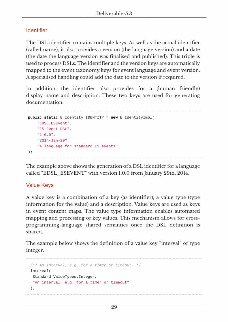
The DSL identifier contains multiple keys. As well as the actual identifier(called name), it also provides a version (the language version) and a date(the date the language version was finalised and published). This triple isused to process DSLs. The identifier and the version keys are automaticallymapped to the event taxonomy keys for event language and event version.A specialised handling could add the date to the version if required.
In addition, the identifier also provides for a (human friendly)display name and description. These two keys are used for generatingdocumentation.
public static E_Identity IDENTITY = new E_IdentityImpl(
"EDSL_ESEvent",
"ES Event DSL",
"1.0.0",
"2014-Jan-29",
"A language for standard ES events"
);
The example above shows the generation of a DSL identifier for a languagecalled “EDSL_ESEVENT” with version 1.0.0 from January 29th, 2014.
Value Keys
A value key is a combination of a key (as identifier), a value type (typeinformation for the value) and a description. Value keys are used as keysin event content maps. The value type information enables automatedmapping and processing of key values. This mechanism allows for cross-programming-language shared semantics once the DSL definition isshared.
The example below shows the definition of a value key “interval” of typeinteger.
/** An interval, e.g. for a timer or timeout. */
interval(
Standard_ValueTypes.Integer,
"An interval, e.g. for a timer or timeout"
),

Deliverable-5.3
30
The DSL framework automatically deals with the following standard valuetypes:
Type Description
String - String value type
Integer - Integer value type
Double - Double value type
Boolean - Boolean value type
TAX_Type - ES taxonomy event type
TAX_Language - ES taxonomy event language
TAX_Source - ES taxonomy event source
DSL_Category - ES DSL category
DSL_Source - ES DSL source
DSL_Dialect - ES DSL dialect
DSL_ValueKey - ES DSL value key
DSL_ValueKeySet - ES DSL value key set
EventDsl - ES DSL object
Map - Standard map
String_List - List of strings
Object - Any object
Domain specific value types can be added for each DSL.
Value Key Sets
A value key set is the combination of a key (as identifier), a list of valuekeys (see above) and a description. In programming languages, it can becompared to the definition a method or function call (they key is thecall name and the set of value keys are the parameters). The examplebelow shows a value key set defined as enumerate with value keys “id” and“reason”:
/** A system shutdown request with reason. */
systemShutdown(
new E_ValueKey[]{ESD_ValueKeys.id, ESD_ValueKeys.reason},
"system shut down request by a server or client"

Deliverable-5.3
31
),
Since value key sets are specific to a domain, no standard sets are defined.However, the ES internal DSLs define their own sets as enumerates, whichmeans they can be easily reused elsewhere.
Dialects
A dialect represents a collection of value key sets. The collection cancontain sets from a single DSL or other DSLs. The collection can be thecomplete set of value key sets or a partial one. The identifier for thedialect is automatically mapped to the event dialect in the event taxonomy.The following example shows the definition of a dialect “ES_EVENTS”as enumerate with display name, collection of value key sets and adescription:
ES_EVENTS(
"ES Server and System Dialect",
new E_ValueKeySet[]{
ESD_ValueKeySets.systemUpdateConnect,
ESD_ValueKeySets.systemUpdateDisconnect,
ESD_ValueKeySets.systemShutdown,
ESD_ValueKeySets.serverReply,
},
"commands and information events for the ES core system"
),
The dialect provides the following additional keys for automatedprocessing:
• A flag to indicate if the dialect should only be used in an automated orif it is also allowed to be used on the command line (empty means notautomated)
• A default event type to indicate what type an auto-generated eventshould have if no type is provided to the builder
• A default value key to indicate what value key should be added by defaultto an event generated for the dialect (empty means none)
• Mappings from and to other value key sets (and thus dialects) to allowfor an automated mapping between dialects. This mapping can for
Deliverable-5.3
32
instance define that an incoming alarm can be automatically mapped toa configuration request and how this mapping should happen.
Categories
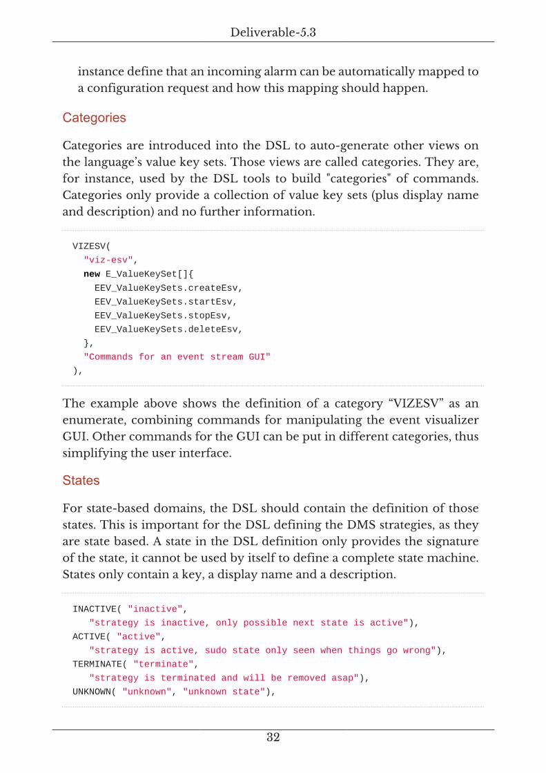
Categories are introduced into the DSL to auto-generate other views onthe language’s value key sets. Those views are called categories. They are,for instance, used by the DSL tools to build "categories" of commands.Categories only provide a collection of value key sets (plus display nameand description) and no further information.
VIZESV(
"viz-esv",
new E_ValueKeySet[]{
EEV_ValueKeySets.createEsv,
EEV_ValueKeySets.startEsv,
EEV_ValueKeySets.stopEsv,
EEV_ValueKeySets.deleteEsv,
},
"Commands for an event stream GUI"
),
The example above shows the definition of a category “VIZESV” as anenumerate, combining commands for manipulating the event visualizerGUI. Other commands for the GUI can be put in different categories, thussimplifying the user interface.
States
For state-based domains, the DSL should contain the definition of thosestates. This is important for the DSL defining the DMS strategies, as theyare state based. A state in the DSL definition only provides the signatureof the state, it cannot be used by itself to define a complete state machine.States only contain a key, a display name and a description.
INACTIVE( "inactive",
"strategy is inactive, only possible next state is active"),
ACTIVE( "active",
"strategy is active, sudo state only seen when things go wrong"),
TERMINATE( "terminate",
"strategy is terminated and will be removed asap"),
UNKNOWN( "unknown", "unknown state"),

Deliverable-5.3
33
The example above shows the life-cycle states of DMS strategies definedas enumerates.
Filters
Each DSL can define a set of standard filters based on the ES filterframework. Standard filters will simplify event processing, for example ina policy or strategy system. The example below shows the creation of a newfilter in a DSL as an enumerate using the filter builder in the enumerateconstructor:
/** Filter for the ES shutdown event. */
SHUTDOWN_EVENT(new ES_EventFilterBuilder()
.withStandardOptions()
.withKeyMembers("f-shutdown", "ST filter", "filter for ST events")
.ofType(ESD_Types.ES_SHUTDOWN)
.fromSource(ESD_Sources.SYSTEM)
.inLanguage(EDSL_ESEvent_1_0_0_Identity.IDENTITY)
.getMapFilter()
),
Note: Filters are immutable. This means that the DSL can only providestandard filters. If a filter needs to be altered later, it can be used with thefilter builder to create a new, specialised filter.
The actual filter builder is not used in the DSL framework to avoid a tightcoupling to that particular implementation.
Protocols
Protocols are currently an experimental feature of a DSL. The intent isto add a formal definition of protocols to a DSL, which can be useful innetwork related DSLs.
Programmatic DSL Tools
The framework provides a DSL event builder and transformers. Thebuilder can be used to create an ES event from a DSL. It does all syntaxand semantic checks automatically and only creates an event if it conformsto a DSL definition (and ultimately to the ES taxonomy with automatedmapping of DSL keys to taxonomy keys).

Deliverable-5.3
34
The framework also provides a set of key and value transformersas a specialisation of the event transformers introduced above. Thesetransformers allow for an automated translation of data from externalsource, such as databases, into correct value types for any DSL.
Standard DSLs
Two standard DSLs are provided:
a. one for events and commands to control the ES messaging system and
b. one with commands to remotely control the event visualizer GUI.
These two DSLs can be used as examples. They use most of the features theframework defines. They also provide for number of standard event typesand value types. Those can be directly reused in other languages.
DSL CLI Tools
The framework also builds a number of command line tools for processingDSL specifications. Those tools allow for automated compilation of asingle DSL or a complete DSL set. Current supported targets for thecompilation, are JavaScript and [asciidoc] (for table-oriented or plain textdocumentation). Other targets can easily be added to the compiler.
2.5.3. Services
Figure 14. ES Services Architecture View
The service package provides a simple service execution framework, aset of classes to generate CLIs for servers (including a simple console),a standard server implementation (the container component for allapplications) and some tools for event processing.

Deliverable-5.3
35
The service execution framework allows for flexible scripting ofdeployments without further code changes (even moving/renaming classesonly requires replicating those name changes in deployment scripts). TheCLI classes come with a set of predefined commands, full console handlingand also automated DSL processing. The latter feature allows registrationof a set of DSLs with a console and let the console take care of theCLI generated from the DSL. No specific CLI, console or server codeis required. An aggregator shell automatically collects all generated DSLshells to create an ueber-shell.
Two tools for event processing are implemented: events-to-file andevents-from-log. Events-to-file connects to the messaging system, receives(currently all) events and stores them in a file (for archiving or further off-line processing). Events-from-log reads events from a file and sends theminto the messaging system.
Service Connectors
Figure 15. ES Service Connectors Composition View
The service connectors are the interfaces to the underlying messagingsystem. These interfaces differ between server and client of the messagingsystem (i.e. not the service package of the ES). Servers and clients use callbacks (back to the application). Client call backs can be restricted to eventreception only or allow also managing the client (i.e. event driven).
2.5.4. Event-Viz
The EventViz (Event Visualizer) is a fully configurable visualisation tool forES event streams using HTML5 technology. The core implementation is

Deliverable-5.3
36
done in JavaScript using SVG graphics on an HTML5 canvas as the front-end. Connectivity to the rest of the DMS is realised using Websockets,which are now a built-in feature of all modern browsers. To run theEventViz component one only needs a HTML5 capable browser withWebsocket support.
Parts of the core implementation are supported by 3PPs. Dependencymanagement between JavaScript modules is managed using Require.js.DOM tree manipulation is realised using jQuery and jQuery-UI. Internalobjects are implemented using Prototype.js. Time information is processedusing Moment.js. Finally, the actual visualisation is realised using Highchartand Highstock. All 3PPs are available as open source for academic andcommercial use, except Highchart and Highstock which need a commerciallicense for commercial use.
The EventViz can be run in online and offline mode. In online mode,all its features can be controlled remotely once the HTML5 backend isloaded and initialised. Once a visualisation has been started and connectedto the DMS event system, it will automatically receive all events and showthem according to the loaded configuration. In offline mode one can usea menu structure to manually load different configurations, which in turnprovide customised visualisations of stored events. The remote controlfor online mode is defined by the DSL EDSL_ESEventViz using the abovedescribed DSL framework. The standard ES shell is providing CLI accessto the language and initiates the communication with the EventViz. Thelanguage defined functions for:
• Create a visualization, including all its HTML5 elements. Creation canbe parameterised with a link to a set of arguments for customisedvisualizations.
• Delete a visualization, including all its HTML5 elements.
• Start/stop a visualisation, which means that once connected one canremotely start and stop the online visualisation of events.
A configuration for the offline mode allows showing all events in a time-sorted manner (the same as for the online mode). It also allows correlatingevents or information from events to show specific aspects of the eventstream.

Deliverable-5.3
37
Zoom From Feb 18, 2015 To Feb 18, 2015
Events
Count
Shell->Strats Shell->Trigger FM Alarm Strat Observe Strat Orient Strat Decide Strat Act Count
Shell->Strats
Shell->Trigger
FM Alarm
Strat Observe
Strat Orient
Strat Decide
Strat Act
5
10
10:38:51.10210:38:46.617 10:38:46.630 10:38:46.639 10:38:46.650 10:38:51.079 10:38:51.110
0.1s 0.5s 1s 5s 10s 20s 30s All
Figure 16. Event Visualiser with Offline Event Stream
Figure 16 shows an offline example of an event stream. On the top, onecan see the events time sorted and normalised using same visual distancebetween the events regardless of their actual timestamp distance. Thisnormalisation is done to emphasise the correlated visualisation on thebottom. The correlation shown here is the count of key/value pairs in eachevent of the event stream. A time line and slider on the bottom allowszooming in and out of a section of the event stream. Other correlations canbe added, as there is no limit to the number of correlation visualisations.
The EventViz will read a configuration file, which can be used to customiseit in virtually any aspect of the visualisation. The events for the eventstream can be specified (including the behaviour of the X and Y axis) andevent filters can be applied, just to name a few options. Most configurableoptions are forwarded to Highchart and Highstock applications, theirrespective documentation can be consulted for all options. Skins andthemes are defined separate of a configuration. At the moment, a standardtheme is provided. This can be customised for any deployment of thevisualizer.
Based on Highchart / Highstock features an event visualisation can beexported as PNG, JPEG, PDF or SVG. This enables to reuse offline andonline visualisations in documentation. The current implementation onlysupports the export as manual feature. Future versions will support thatwith remote control as well. The visualisation in Figure 16 was manuallyedited SVG export of an offline mode visualisation.
Deliverable-5.3
38
2.5.5. Generic State Machine
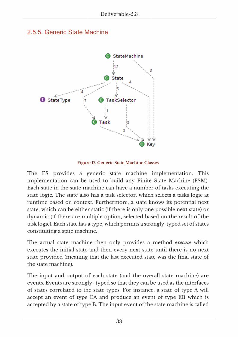
Figure 17. Generic State Machine Classes
The ES provides a generic state machine implementation. Thisimplementation can be used to build any Finite State Machine (FSM).Each state in the state machine can have a number of tasks executing thestate logic. The state also has a task selector, which selects a tasks logic atruntime based on context. Furthermore, a state knows its potential nextstate, which can be either static (if there is only one possible next state) ordynamic (if there are multiple option, selected based on the result of thetask logic). Each state has a type, which permits a strongly-typed set of statesconstituting a state machine.
The actual state machine then only provides a method execute whichexecutes the initial state and then every next state until there is no nextstate provided (meaning that the last executed state was the final state ofthe state machine).
The input and output of each state (and the overall state machine) areevents. Events are strongly- typed so that they can be used as the interfacesof states correlated to the state types. For instance, a state of type A willaccept an event of type EA and produce an event of type EB which isaccepted by a state of type B. The input event of the state machine is called

Deliverable-5.3
39
trigger (since it triggers the execution of the state machine). The outputevent of the state machine is called action since it contains the results ofthe executed state.
This state machine can be used anywhere. It is used to build DMS strategiesand provides the execution environment for them. All that an applicationusing the state machine needs to add is a threading model (if multiple statemachines have to be executed in parallel) and a trigger/action mechanism.
2.5.6. Overview of ES Tools
Figure 18. ES Tools
The set of tools provided by the ES cover event handling and DSLprocessing. The event handling tools are base implementations to readevents from logs or archives and to build and send event streams using theoriginal event’s headers, including the time stamps.
The DSL processing tools are compilers for DSL sets (e.g. all DSLs ina package or a hierarchy of all DSLs and all of their versions in apackage) and single event DSLs. The tools also compile the underlyingevent taxonomy, to provide documentation and for generation of sharedsemantics for the EventViz. Thus, the compile targets are asciidoc withtables (documentation), asciidoc using plain text (documentation) and

Deliverable-5.3
40
JavaScript (EventViz or other JavaScript-based applications). Generationof HTML documentation can be done using the generated asciidoc. Moretargets can easily be created as required in either the ES package or asspecialisation of the existing tools.
2.5.7. Backend – Automated Execution and standard CLI
Figure 19. ES Backend with Service Execution and Standard CLI
The ES backend system provides a number of common functions andclasses.
• ES_Service provides an interface that ES services can use for easyexecution. Combined with ES_Exec, this interface allows to findexecutable ES services at runtime, query their CLI and invoke them byfixed identifier (application synonym) or dynamically by their packageand class name. This facilitates DevOps style scripting to run a set

Deliverable-5.3
41
of services independent of the internal implementation or executionenvironment.
• ES_Cli and ES_CliOptions provide a standard CLI parser and standardoptions that can be reused by all ES services.
• ES_System provides standard functions e.g. for generation of identifiers,handling of system properties and standard console handling.
• ES_Console provides access to standard in and standard out using alogging service. This allows to write servers and console applicationswithout direct access to standard consoles, configurable at executiontime to either use them and/or other output mechanism.
A generic return object is also provided that allows defining functions thatcan return a status of execution along with an actual return value. Thiseliminates the need to return nulls from functions and all ES applicationsshould use ES_ReturnObject instead.
2.5.8. Standard Event DSLs
The ES defines a set of standard DSLs using the DSL framework. Thestandard ES Language is used to, internally, control executed servers andclients of an ES event system. It provides the means for the servers/clientsto build synchronous communication (request/reply) over otherwiseasynchronous event systems, handle client/server registrations and toinitiate a controlled system shutdown. The EventViz language contains allfunctions to remotely control the Event Visualisation component.
2.6. Detailed Description – 2-ES-WS
Figure 20. ES Websocket Connectors
The package 2-ES-WS implements Websocket connectors for theDMS-ES. These connectors are essentially implementations of the ESservice connector interfaces using Websockets, plus a Websocket specific
Deliverable-5.3
42
implementation of the ES tools for event processing. The package comeswith a specialisation of the ES execution service to allow for runtime accessto all implemented connectors (and standard servers and clients).
The Websocket server will listen on the default port (8887)or a specified port. The clients will use the default host(localhost) and the default port (8887) for connections if notinstructed otherwise. The default logging port is 8889.
2.7. Detailed Description – 2-ES-ZK
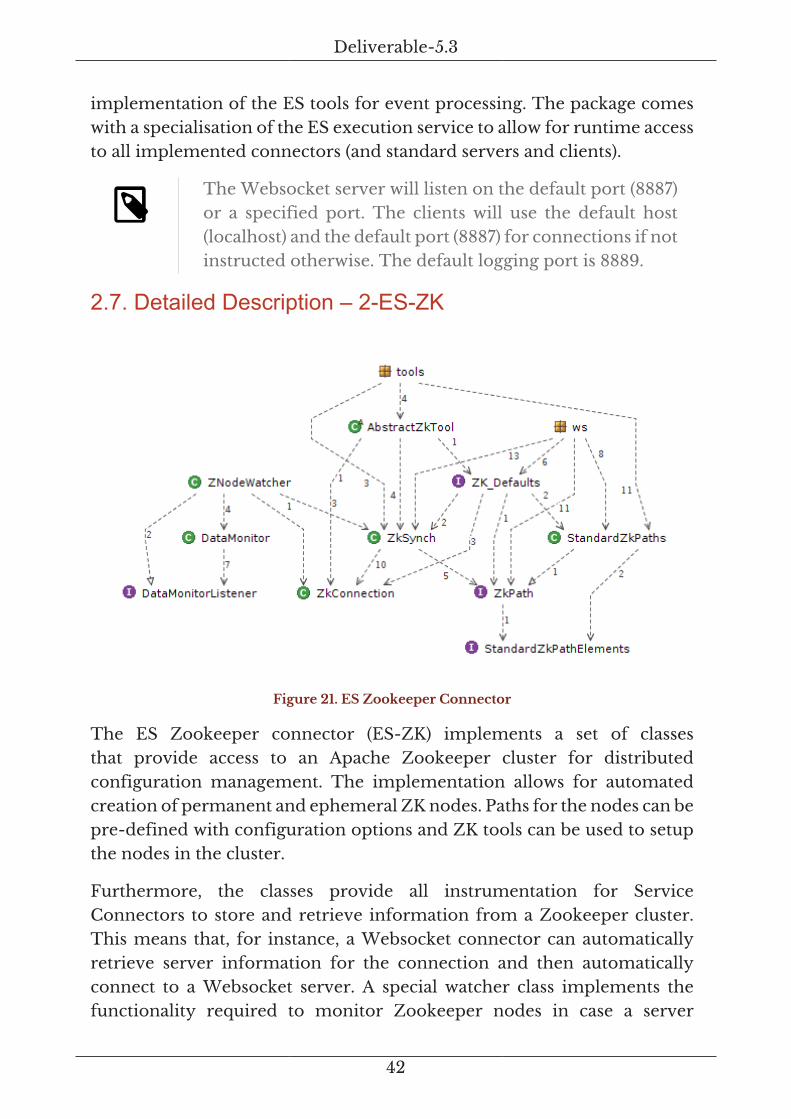
Figure 21. ES Zookeeper Connector
The ES Zookeeper connector (ES-ZK) implements a set of classesthat provide access to an Apache Zookeeper cluster for distributedconfiguration management. The implementation allows for automatedcreation of permanent and ephemeral ZK nodes. Paths for the nodes can bepre-defined with configuration options and ZK tools can be used to setupthe nodes in the cluster.
Furthermore, the classes provide all instrumentation for ServiceConnectors to store and retrieve information from a Zookeeper cluster.This means that, for instance, a Websocket connector can automaticallyretrieve server information for the connection and then automaticallyconnect to a Websocket server. A special watcher class implements thefunctionality required to monitor Zookeeper nodes in case a server

Deliverable-5.3
43
terminates abnormally and then re-establish a connection once the serveris started again.
• ZK_Defaults maintains the default connection parameters forZookeeper. They are used if no parameters are given programmaticallyor via CLI.
• ZkSync is a higher level object maintaining information on a Zookeepernode. It is initialised with a ZkConnection object for the initial connectionto a cluster. It can also be used with a watcher for monitoring ofchanges in the node, e.g. removal of nodes, changes of node content orappearance of nodes. A message system server for instance can createan ephemeral node with connection parameters and a ZkSync object can“watch” this node and change the connection to that server when theparameters change.
• Standard paths and ZkPaths realise standard path assembly based onpath elements. A path can be configured as static or ephemeral, allowingCLI tools to create initial cluster configurations. The default connectiondetails are maintained by Zk_Defaults.
• AbstractZkTool provides the skeleton for building tools with Zookeeperconnection. The implemented tools are ZkTool_Init and ZkTool_Reset.Here, “init” means to create all paths on a cluster and “reset” meansto remove all paths from the cluster. Paths refers to the standardpaths in StandardZkPaths, which are constructed from path elements inStandardZkPathElements.
Using ZkDefaults the default host is localhost (127.0.0.1). Thedefault port is 2181. The default timeout for a connectionsetup is 5000 ms. The default logger port is 2138.
2.8. Detailed Description – 2-ES-WS-ZK
Figure 22. ES Websocket-Zookeeper Connectors
Deliverable-5.3
44
The package 2-ES-WS-ZK combines the Websocket connector withthe Zookeeper connector. It extends the original 2-ES-WS tools withautomated runtime configuration using Zookeeper. Using this connector,the CLI applications (servers and clients) can connect automaticallyto a Zookeeper cluster (using either default parameters or given CLIparameters) and read all relevant Websocket parameters from there. Nofurther configuration on the applications is required.
This package allows for (almost, if no special ZK parameters are required)zero configuration of a complete DMS deployment.
2.9. Detailed Description – 3-ES-DSLs
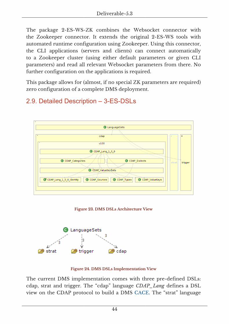
Figure 23. DMS DSLs Architecture View
Figure 24. DMS DSLs Implementation View
The current DMS implementation comes with three pre-defined DSLs:cdap, strat and trigger. The “cdap” language CDAP_Lang defines a DSLview on the CDAP protocol to build a DMS CACE. The “strat” language

Deliverable-5.3
45
Strat_Lang defines a set of functions to deploy, load, start, change andterminate strategies on a DMS manager via a remote interface, usuallya CLI. The “trigger” language Trigger_Lang defines an experimentallanguage to issue triggers into the DMS for demonstration or testingpurposes. All DSLs are defined using the ES DSL framework.
2.9.1. CDAP_Lang
The CDAP language represents a 1-to-1 mapping of the CDAP protocolstandard into an ES DSL. The value keys are taken from the PRISTINECDAP implementation (see Section 4.2.3). The value key sets are the sixbasic operations that CDAP uses (create/delete, start/stop, read/write) intheir request and response versions, plus the operation cancel-read. Thecurrent CDAP language is built April 20, 2015 as version 1.0.0.
The language only defines one type: ES_CDAP as a CDAP message.Other types might be added in the future for instance to tag notificationsdifferently from other CDAP messages for faster filtering and processing.The DMS Manager and the DMS Agent are the only Event sources withinthe DMS. Other source can be added if required, for instance ,when legacysoftware is integrated into a DMS system.
The language uses two different dialects: one for requests and one forresponses. The request dialect is non-automatic; it can be used in anyapplication context. The response dialect is automatic; it can only be usedas a response to a request but not for instance from a CLI.
The language defines a number of categories to group CDAP operationsin the CLI or other interfaces: OP (standard operation), OP_R (a response),CONN (connection handling operations), CONN_R (the response of aCONN) and ADD (additional operations, currently cancel read request andresponse).
2.9.2. Strat_Lang
The Strategy language defines all means to remotely deploy, start, stop andalter strategies on a DMS manager. The current language is built January20, 2015 as version 1.0.0.
The language defines two value keys, one to define what triggers a strategycan have and one to define what trigger context a strategy is able to process.All other value keys are taken from the ESD_ValueKeys defined in the ES.
Deliverable-5.3
46
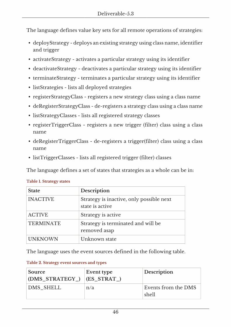
The language defines value key sets for all remote operations of strategies:
• deployStrategy - deploys an existing strategy using class name, identifierand trigger
• activateStrategy - activates a particular strategy using its identifier
• deactivateStrategy - deactivates a particular strategy using its identifier
• terminateStrategy - terminates a particular strategy using its identifier
• listStrategies - lists all deployed strategies
• registerStrategyClass - registers a new strategy class using a class name
• deRegisterStrategyClass - de-registers a strategy class using a class name
• listStrategyClasses - lists all registered strategy classes
• registerTriggerClass - registers a new trigger (filter) class using a classname
• deRegisterTriggerClass - de-registers a trigger(filter) class using a classname
• listTriggerClasses - lists all registered trigger (filter) classes
The language defines a set of states that strategies as a whole can be in:
Table 1. Strategy states
State Description
INACTIVE Strategy is inactive, only possible nextstate is active
ACTIVE Strategy is active
TERMINATE Strategy is terminated and will beremoved asap
UNKNOWN Unknown state
The language uses the event sources defined in the following table.
Table 2. Strategy event sources and types
Source(DMS_STRATEGY_)
Event type(ES_STRAT_)
Description
DMS_SHELL n/a Events from the DMSshell

Deliverable-5.3
47
Source(DMS_STRATEGY_)
Event type(ES_STRAT_)
Description
OBSERVE OBSERVE Events send by a DMSstrategy (observe state)
ORIENT ORIENT Events send by a DMSstrategy (orient state)
DECIDE DECIDE Events send by a DMSstrategy (decide state)
ACT ACT Events send by a DMSstrategy (act state)
The language defines two dialects: STRAT__SM_CMD for CLI or otherwiseissued commands to control strategies (non-automatic dialect) andSTRAT_STATES for events that are issued by particular active states of astrategy for logging or visualisation purposes (automatic dialect).
The language defines a set of categories for CLI and other user interfaces:STRATEGY for strategies, TRIGGER for triggers and STRATEGY_CLASSESfor everything related to strategy classes.
There are no other types defined. However, future use of the languagemight lead to the definition of new types to allow for a fine-grainedfiltering of the different operations for strategies once more complex DMSdeployments require it.
2.9.3. Trigger_Lang
Figure 25. Trigger DSL implementation
The trigger language is an experimental language used to send triggersinto the DMS for testing or demonstration purposes. It defines functionsfor listing, explaining and sending triggers. It also provides a function toregister a trigger provider as an experimental trigger source for a DMS. Thecurrent language is built February 17, 2015 as version 1.0.0.

Deliverable-5.3
48
The language comes with one dialect and one category covering all definedfunctions (value key sets). Additionally, the language defines a standardfilter for triggers, which can be used by strategies to test or demo manuallysend triggers. The only defined source is trigger shell for manually sendingtriggers into the DMS.
2.10. Detailed Description – 3-Strategies
The DMS strategies are built on top of the generic state machine of theEvent System (ES). This allows building virtually any type of managementpolicy. For the current version of the DMS, we have implemented strategiesusing a four state Observe-Orient-Decide-Act(OODA) loop [boyd96].
For the DMS strategies, we are using these states in the following way.
ObserveMonitors an event stream (including notifications, which are specialcases of events). The task of the monitoring is to detect an event (or a setof events) that will trigger the strategy. While we can define a complexset of events representing a trigger, the recommended way to realise theObserve state is to define a single event as trigger and use the content ofthe event as contextual information about the trigger. This means thatwe can move the complex event processing outside of the strategy, andthen make use of existing Complex Event Processing (CEP) systems todo the heavy lifting.
OrientTakes the incoming event (trigger) and its payload (context) andshapes the way the strategy can observe, decide and act. It is themost important state in the strategy. Using the trigger and genericheritage (e.g. a business goal for the DMS), cultural traditions (e.g.the way a particular department manages a network or a DIF), newinformation (external data sources that can be accessed by the strategyto collect additional information), previous experience (historical dataon previous executions of the strategy or the wider DMS if possible),and analysis and synthesis (e.g. means to describe the observed situationusing all the above data and information). Note: the situation that Orientcan describe can (i.e. will) vary from trigger to trigger and thus fromexecution to execution. This means that with an intelligent Orient state,the strategy can become a very powerful tool of the DMS.

Deliverable-5.3
49
DecideBased on the realised orientation, this state decides what to do aboutit. This decision (or this set of decisions), following Boyd, describes ahypothesis, i.e. it is not necessarily a final decision as we see in ActionPolicies (or ECA Policies). Rather it states what should be done and whyit should be done to deal with the observation and the orientation.
ActIs taking the decision and finding the best way to realise it. This“best way” can be dependent on the decision, time, location, or othercontextual information. It most certainly depends on the availabilityof Management Agents and other resources that can be instructed torealise the decision. This also means that this state translates the decisionof the strategy into an action for the Management Agent (in RINA aconfiguration change on a RIB object).
According to Boyd, any taken action results in unfolding interactions withthe environment. This means that by changing a configuration, a strategycan create new events that can be picked up by it or other strategies. Thismechanism used carefully, can realise chaining of strategies. It also can beused to provide powerful strategies that can understand the impact of theirdecisions.
Figure 26. Strategies Software Architecture
The software architecture realising OODA strategies, their triggering andtheir execution for the DMS uses the same event-driven mechanism as
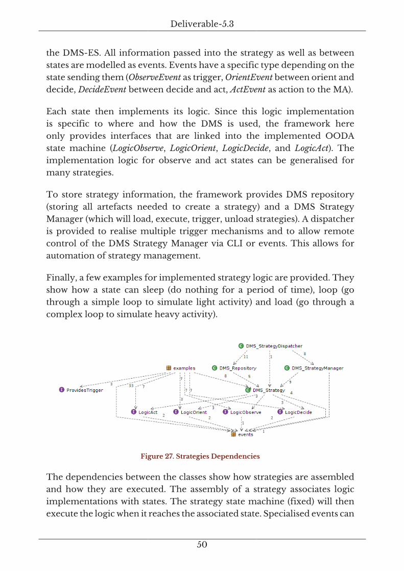
Deliverable-5.3
50
the DMS-ES. All information passed into the strategy as well as betweenstates are modelled as events. Events have a specific type depending on thestate sending them (ObserveEvent as trigger, OrientEvent between orient anddecide, DecideEvent between decide and act, ActEvent as action to the MA).
Each state then implements its logic. Since this logic implementationis specific to where and how the DMS is used, the framework hereonly provides interfaces that are linked into the implemented OODAstate machine (LogicObserve, LogicOrient, LogicDecide, and LogicAct). Theimplementation logic for observe and act states can be generalised formany strategies.
To store strategy information, the framework provides DMS repository(storing all artefacts needed to create a strategy) and a DMS StrategyManager (which will load, execute, trigger, unload strategies). A dispatcheris provided to realise multiple trigger mechanisms and to allow remotecontrol of the DMS Strategy Manager via CLI or events. This allows forautomation of strategy management.
Finally, a few examples for implemented strategy logic are provided. Theyshow how a state can sleep (do nothing for a period of time), loop (gothrough a simple loop to simulate light activity) and load (go through acomplex loop to simulate heavy activity).
Figure 27. Strategies Dependencies
The dependencies between the classes show how strategies are assembledand how they are executed. The assembly of a strategy associates logicimplementations with states. The strategy state machine (fixed) will thenexecute the logic when it reaches the associated state. Specialised events can

Deliverable-5.3
51
be created and consumed by the logic implementation, the state machineensures that they are exchanged between the appropriate states.
The DMS repository picks up strategies (complete sets) as well as logicimplementations (to allow for runtime assembly of strategies). Once theyare deployed in a repository at runtime, the DMS Strategy Manager can beinstructed to use them. The dispatcher provides the runtime interface fordoing that remotely using the Strategy DSL.
An additional interface, ProvidesTrigger, can be used to generate triggers fordemonstration and testing purposes. An implementation of this interfacewill realise a trigger that a strategy is looking for in the observe state. TheTrigger DSL contains all required functions and a specific shell can be usedto control triggers.
2.11. Detailed Description – 3-RIB
The RIB implementation for the DMS consists of two parts:
a. The RIB-Model package defines the model in an abstract syntax andprovides tools to generate code from that model. .The RIB package isthe target for the generated code, i.e. it contains all auto-generated Javaclasses generated from the RIB-Model.
The model currently defined and used for code generation is the PRISTINERIB model. However, the mechanism described here can be extended toother RIB models, virtually any number of them. For instance, one candefine a WiFi RIB model or a USB RIB model and generate the code forthem using the RIB tools.
The definition of the RIB model is separated into four different parts, eachcontained in a separate file. The abstract syntax being used throughout isJSON.
2.11.1. Attribute Types (attribute-types.json)
This is a collection of all types that can be used for attributes in thisRIB Model. Types are essentially synonyms to a particular behaviour andallowed values. For instance, a type “Boolean” can have two distinct values0 or 1 (or in different representations: true or false). A type “list” represents

Deliverable-5.3
52
an object that contains a (not further qualified) list of values. Furtherspecialisations of list can indicate a list holding only a given type or listswith particular characteristics for insertion, deletion and sorting order.
{"id":"APP_NAMING_INFO", "description":"Type for an App Naming Info"},
{"id":"AVAILABLEDIF", "description":"Type for an Available DIF"},
{"id":"BOOLEAN", "description":"Type for a Boolean"},
2.11.2. Attributes (attributes.json)
Attributes consists of an identifier and a type. The identifier must be uniquein the RIB model. The type must be one of the attribute types defined inthe model.
{"id":"address", "type":"INTEGER", "description":"###"},
{"id":"addressLength", "type":"INTEGER", "description":""},
{"id":"allocateNotifyPolicy", "type":"POLICY_CONFIG", "description":""},
2.11.3. Nodes (nodes.json)
Nodes are objects in the RIB model tree that may contain attributes. A nodehas an identifier and an attribute list. This list can be empty (no attributes)or contain any attribute defined in the model. Each attribute can only becontained once, e.g. a node “DTCP” can contain one (and only one) attribute“flowControl”.
{"id":"SecurityManagement",
"attributes":
["auditingPolicy", "credentialManagementPolicy"], "description":""},
{"id":"Neighbor",
"attributes":["processName", "processInstance", "address",
"underlayingDIFs", "underlayingFlows", "authenticationPolicy",
"numberOfEnrollmentAttempts"], "description":""},
{"id":"Neighbors",
"attributes":[], "description":""},
{"id":"Enrollment",
"attributes":
["enrollmentPolicy", "newMemberAccessControlPolicy"], "description":""},
Deliverable-5.3
53
2.11.4. Edge Containment (edges-containment.json)
Edges define a containment relationship for nodes. An edge has a source(the container) and a target (the containment). Source and target can be anynode defined in the model. An edge can furthermore define a cardinalityfor the targets, effectively realising lists (or arrays) of targets. A cardinalityof -1 means any number. By defining the edges (and the nodes) one cancreate the tree that the RIB model represents.
{"source":"ComputingSystem", "target":"ProcessingSystems", "cardinality":-1},
{"source":"ComputingSystems", "target":"ComputingSystem", "cardinality":-1},
{"source":"Connection", "target":"DTCP", "cardinality":-1},
{"source":"DAF", "target":"ManagementAgents", "cardinality":-1},
{"source":"DAFs", "target":"DAF", "cardinality":-1},
2.11.5. Code Generation
The code generator (CodeGen) takes the RIB model definitions describedabove and creates Java classes implementing the attribute types and thenodes with the given containment. Type class names start with T_. Nodeclass names start with RO_ (RIB object). For the nodes, there attributes aregenerated as private members with automated default initialisation andgetter/setter methods on the node class.
The code generator also generates Java enumerates for each of the fourdefinition files to provide easy, programmatic access to the originaldefinition.
The current target for the code generator is Java (Java classes). However,the code generator is implemented to be easily extend-able for othertargets, e.g. [asciidoc] for documentation, JavaScript or other programminglanguage. The code generation is driven by StringTemplates and allinformation required to activate and use a particular template ismaintained in the code generation target description (CodeGenTarget). Thisis the same mechanism as used for the Event DSL code generator of theDMS ES.
2.12. Detailed Description – 4-Manager
The manager provides a container for strategies. It uses the Event DSLsdescribed above for strategy management. It uses the underlying DMS

Deliverable-5.3
54
Event system for all communication, effectively providing an CACE forDMS management applications. The implementation of the manager doesnot employ the RIB model, since that will be in the scope of specificstrategies one can implement using the DMS.
Figure 28. DMS 4-Manager packages and dependencies
The software architecture of the manager shows how three differentapplications are implemented and then the ES service connectors are usedto link them to the underlying event system.
The first application is the DMS Manager. It maintains and executesstrategies. The functionality of the manager is defined in the Strategy DSLand implemented by the Strategy Dispatcher. The manager applicationsimply provides a container for a controlled deployment and execution ofthe strategies. Thus the implementation is very simple.
The second component is the DMS Shell. It takes the Strategy DSL andprovides a CLI interface to remotely control a DMS Manager (usingthe event system). The DMS ES already implements a shell that cantake an Event DSL and auto-generate a CLI for it. Thus the DMS shellimplementation takes the Strategy DSL and uses the ES shell to build theCLI at runtime. It then forwards console input to the auto-generated CLIand prints out return messages to the console.
The third component is a Trigger Shell, which uses the Trigger DSLfor sending test and demo triggers to the DMS Manager to test strategy

Deliverable-5.3
55
behaviour without an actual managed system being present. It basicallyimplements logic for all commands from the Trigger DSL.
Figure 29. DMS 4-Manager application architecture
Figure 30. DMS 4-Manager application packages
The three applications are then linked to the service connectors for plainWebsockets (WS_*) and the Websocket/Zookeeper connector (ZKWS_*).The applications can then be deployed in any of the two messaging system.Other connectors can be added once they become available in the DMS ES.
2.13. External Dependencies
All code for the DMS was written from scratch. One of the goals for theimplementation was to keep dependencies to external libraries and 3PPsto a minimum. The following dependencies do exist in the code (they areall open source projects):
• SLF4J – used in the DMS ES for logging as well as for console output. Thelatter one is implemented as a specific case of logging. This means thatthe behaviour of all console outputs (prints) can be externally configuredthe same way that logging can be configured. Since SLF4J is only alogging framework, several logging backends can be added at compiletime and then configured at runtime. The standard backend used in the

Deliverable-5.3
56
DMS ES is logback. SLF4J documentation can be found here: http://www.slf4j.org/
• Jackson – all conversions from and to JSON are using the Jacksonlibraries. They provide for fast and proven JSON infrastructure.Documentation on Jackson can be found here: https://github.com/FasterXML/jackson
• Stringtemplate – this is a library that allows defining templates fortext generation, which can then be included into a compiler orcode generator. The template language is simple yet very powerful.By externalising the code generation into templates one can changethe target output without changing actual compiler code. All codegenerators (Event DSL, RIB) use Stringtemplates. Documentation onthe library and the template language can be found here: http://www.stringtemplate.org/
• Websocket – this is a communication standard maintained byW3C. The standard is about to be final. There exist manydifferent implementations with various levels of functionality. Theimplementation used in the DMS ES can be found here: http://java-websocket.org/
• Apache Zookeeper – is used for external, distributed configurationmanagement. The ES-ZK and ES-WS-ZK packages are implementingZookeeper functionality. To use Zookeeper, one will need to downloadthe software package for a host operating system, install and configureit. Documentation for Zookeeper (API and system) can be found here:https://zookeeper.apache.org
• Apache Commons – the commons packages provide proven solutionsfor common programing situations. The DMS ES is using theCLI implementation (https://commons.apache.org/proper/commons-cli) and the common language tools (https://commons.apache.org/proper/commons-lang).
• Asciidoc – is a markup language and compiler for generating documentsusing simple ASCII text documents[asciidoc]. Asciidoc is used in theDMS ES to generate documentation as well as a target for Event DSLcompilers. The generated text files are then processed using a toolto generate HTML files. The DMS ES is using the asciidoc Mavenplugin[adoctor15] for automated processing.

Deliverable-5.3
57
The EventViz component uses a number of JavaScript libraries as externaldependencies. Those libraries are only required if the EventViz componentis used. The external libraries need to be loaded into the Browser, which isdone automatically by the deployed manager component.
• Require – is a package that helps to maintain dependencies and to loaddependencies. Details can be found here: http://requirejs.org/
• Prototype – is used to define classes and inheritance for JavaScriptobjects in the EventViz. Documentation can be found here: http://prototypejs.org/
• jQuery – is used for direct DOM manipulations to load graphicDIV elements and to manipulate graphic and text for the visualiser.Documentation can be found here: https://jquery.com/
• jQueryUI – is used for several graphical elements. Documentation canbe found here: https://jqueryui.com
• Moment – is used to deal with all time information. Documentation canbe found here: http://momentjs.com
• Highcharts – the event stream visualisation uses Highcharts andHighstock as backend. These two libraries provide a large andextensively customisable set of graphs. The EventViz uses a number ofthose graphs with specific configurations. The external configuration ofthe EventViz is then mapped (in large parts) directly to the Highchartgraphs. Documentation on the API and the graphs can be found here:http://www.highcharts.com/
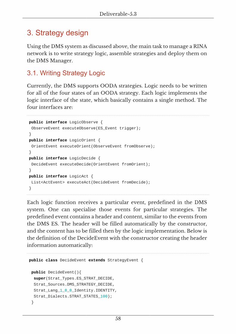
Deliverable-5.3
58
3. Strategy designUsing the DMS system as discussed above, the main task to manage a RINAnetwork is to write strategy logic, assemble strategies and deploy them onthe DMS Manager.
3.1. Writing Strategy Logic
Currently, the DMS supports OODA strategies. Logic needs to be writtenfor all of the four states of an OODA strategy. Each logic implements thelogic interface of the state, which basically contains a single method. Thefour interfaces are:
public interface LogicObserve {
ObserveEvent executeObserve(ES_Event trigger);
}
public interface LogicOrient {
OrientEvent executeOrient(ObserveEvent fromObserve);
}
public interface LogicDecide {
DecideEvent executeDecide(OrientEvent fromOrient);
}
public interface LogicAct {
List<ActEvent> executeAct(DecideEvent fromDecide);
}
Each logic function receives a particular event, predefined in the DMSsystem. One can specialise those events for particular strategies. Thepredefined event contains a header and content, similar to the events fromthe DMS ES. The header will be filled automatically by the constructor,and the content has to be filled then by the logic implementation. Below isthe definition of the DecideEvent with the constructor creating the headerinformation automatically:
public class DecideEvent extends StrategyEvent {
public DecideEvent(){
super(Strat_Types.ES_STRAT_DECIDE,
Strat_Sources.DMS_STRATEGY_DECIDE,
Strat_Lang_1_0_0_Identity.IDENTITY,
Strat_Dialects.STRAT_STATES_100);
}

Deliverable-5.3
59
}
Once the logic for each state is implemented, one can create a new Strategyclass using those implementations. For example, we implement an observelogic that simply takes the incoming trigger event (a standard DMS ESevent) and copies all its contents to an outgoing observe event (using thespecial ObserveEvent class). If the trigger contains a key called “trigger” withthe contents “myTrigger”. We call the class D53_Observe and could beimplemented as follows.
public class D53_Observe implements LogicObserve {
@Override
public ObserveEvent executeObserve(ES_Event trigger) {
if(trigger.getString("trigger").equals("myTrigger")){
ObserveEvent ret = new ObserveEvent();
ret.getContents().putAll(trigger.getContent());
return ret;
}
return null;
}
}
Now we can implement the logic for the orient state which will receive thecreated ObserveEvent. The example below is kept simple: it takes the triggerfrom the observe event and copies it into the orient event. Then it adds akey “office” with either true (if triggered between 9am and 5pm) or false(if triggered between 5pm and 9am) value. This means that “myTrigger”has been received within or outside office ours. The orient logic also addsinformation about a key “system” set to “”XML-CONFIG”.
public class D53_Orient implements LogicOrient {
@Override
public OrientEvent executeOrient(ObserveEvent fromObserve) {
OrientEvent ret = new OrientEvent();
ret.getContents().put("trigger",
fromObserve.getContents().get("trigger"));
LocalDateTime timePoint = LocalDateTime.now();
int h = timePoint.getHour();
int m = timePoint.getMinute();
if((h>9 && h<18) && (m>=00 && m<=59)){
ret.getContents().put("office", true);

Deliverable-5.3
60
}
else{
ret.getContents().put("office", false);
}
ret.getContents().put("system", "XML-CONFIG");
return new OrientEvent();
}
}
Now we can implement the logic for the decide state. Again, the actual logicis kept simple and only selects an office configuration if we are in an officesituation and a closed configuration if not. If the situation is undecided, thelogic does not make any decision.
public class D53_Decide implements LogicDecide {
@Override
public DecideEvent executeDecide(OrientEvent fromOrient) {
Boolean office = (Boolean)fromOrient.getContents().get("office");
if(office==true){
DecideEvent ret = new DecideEvent();
ret.getContents().put("config", config.Office());
ret.getContents().put("system",
fromOrient.getContents().get("system"));
return ret;
}
else if(office==false){
DecideEvent ret = new DecideEvent();
ret.getContents().put("config", config.OutOfOffice());
ret.getContents().put("system",
fromOrient.getContents().get("system"));
return ret;
}
else{
return null;
}
}
}
Finally, we can write the logic for the act state. We receive a decide eventthat states what configuration has to be used. Depending on the preferredconfiguration system (from orient) and the availability of that preferredconfiguration system, the specific configuration file is then sent to theconfiguration systems.

Deliverable-5.3
61
public class D53_Act implements LogicAct {
@Override
public List<ActEvent> executeAct(DecideEvent fromDecide) {
List<ActEvent> ret = new ArrayList<>();
ActEvent retA = null;
switch((String)fromDecide.getContents().get("system")){
case "XML-CONFIG":
if(xmlCfg.isAvailable){
retA = new ActEvent();
retA.getContents().put("for", "xmlConfig");
retA.getContents().put("config",
(Config)fromDecide.getContents().get("config").toXml());
}
break;
case "JSON-CONFIG":
if(jsonCfg.isAvailable){
retA = new ActEvent();
retA.getContents().put("for", "jsonConfig");
retA.getContents().put("config",
(Config)fromDecide.getContents().get("config").toJSON());
}
break;
case "CHEF-CONFIG":
if(chefCfg.isAvailable){
retA = new ActEvent();
retA.getContents().put("for", "jsonConfig");
retA.getContents().put("config",
(Config)fromDecide.getContents().get("config").toChef());
}
break;
default:
break;
}
if(retA==null){
//create error about unavailable configuration system
}
ret.add(retA);
return ret;
}
}
All logic for all states is implemented now.

Deliverable-5.3
62
3.2. Assemble a Strategy
Assembling already implemented logic simply means to create a new DMSStrategy class as follows.
public class D53_Strategy extends DMS_Strategy {
public D53_Strategy(){
this.setObserve(new D53_Observe());
this.setOrient(new D53_Orient());
this.setDecide(new D53_Decide());
this.setAct(new D53_Act());
}
}
This new strategy class (D53_Strategy) can now be compiled and theresulting jar added to a DMS Manager classpath. Once the jar is deployed,the strategy can be executed and added to the DMS Manager.
3.3. Implement a Strategy Trigger
For each strategy, the DMS Manager needs an associate trigger. Thetrigger can be implemented using ProvidesFilter interface. Additionally, theinterface ProvidesTrigger can be used to create test and demo triggers forthe strategy. Below the implementation of a simple trigger for the strategyD53.
public class D53_Trigger implements ProvidesFilter, ProvidesTrigger {
protected ES_EventFilter filter;
public D53_Trigger() {
this.filter = new ES_EventFilterBuilder()
.withStandardOptions()
.withKeyMembers(D53_Trigger.class.getName(),
D53_Trigger.class.getSimpleName(), "example policiy: simple filter for
D53 events")
.ofType(ESD_Types.ES_EVENT_FM)
.inLanguage("D53_EXAMPLES")
.inDialect("D53_EXAMPLES Dialect")
.ofVersion("1.0.0")
.mustContain(ESD_ValueKeys.info, "D53 Test Trigger")

Deliverable-5.3
63
.mustNotContainKey(Strat_ValueKeys.context)
.getMapFilter()
;
}
@Override
public ES_EventFilter getFilter(){
return this.filter;
}
@Override
public ES_Event triggerEvent() {
Map<Object, Object> t1Map = new HashMap<>();
t1Map.put(ESD_ValueKeys.info.getName(), "D53 Test Trigger");
t1Map.put(ESD_ValueKeys.name.getName(), "myTrigger");
t1Map.put(ESD_ValueKeys.reason.getName(), "test trigger");
return new ES_EventBuilder()
.setType(ESD_Types.ES_EVENT_FM)
.setLanguage("D53_EXAMPLES")
.setDialect("D53_EXAMPLES Dialect")
.setVersion("1.0.0")
.setSource(TriggerSim_Sources.TRIGGER_SHELL)
.setContent(t1Map)
.event();
}
}
The trigger class can now be compiled and the resulting jar added to theDMS Manager classpath.
3.4. Deploy and Activate a Strategy
Using the DMS shell the deployment and activation of the newly createdstrategy D53_Strategy can be done with the following commands.
# sm registerStrategyClass
className:eu.ict_pristine.wp5.dms.strategies.examples.D53.D53_Strategy
# sm registerTriggerClass
className: eu.ict_pristine.wp5.dms.strategies.examples.d53.D53_Trigger
# sm deployStrategy
className: eu.ict_pristine.wp5.dms.strategies.examples.d53.D53_Strategy,
id:d53,

Deliverable-5.3
64
trigger:eu.ict_pristine.wp5.dms.strategies.examples.d53.D53_Trigger
# sm activateStrategy id:d53
Once the strategy is activated it will be triggered by the DMS Manager if anincoming event matches the filter of the associated trigger object.

Deliverable-5.3
65
4. Agent design
In D5.2 section 5 [D52], we described the high level architecture of theManagement Agent (MA) and we detailed some of its components. We alsodescribed the workflow of the MA and some of its requirements.
In this section we are going to explain the updates on the MA architecture,the implementation decisions that have been agreed between the partnersand the scenarios that have been set to test the MA functionalities.
4.1. Architecture updates
The development of the Management Agent (MA) has inspired a new visionon the foreseen architecture of the IPC manager. The IPC manager isthe daemon in charge of controlling and managing various IPC processes,which means that it has to allow a proper communication within the system(between the IPC processes) and outside the system (between the IPCprocesses and the user). The main IPC manager responsibilities are:
a. To provide an interface for the management of various IPC Processes.
b. To effectively manage the IPC processes.
In the IRATI stack architecture, the management agent has always beenmodeled as a daemon (process) with the following requirements:
1. To provide a console to the end-user to control and monitor variousIPC processes.
2. To be able to configure a DIF with different policies provided by theuser.
3. To control an monitor the state of the managed IPC processes. Allowingcreation, registration, assignment and destruction of IPC processes.
These three requirements has been achieved by the IRATI stack with asingle software module and daemon called IPC manager. However, thedevelopment of a new functionality in PRISTINE, the MA, has arisen theneed of an architectural change. Note that the MA requirements have manysimilarities with the requirements of the IPC manager, since the MA hasto be able to provide an interface to the DMS Manager, has to be able to
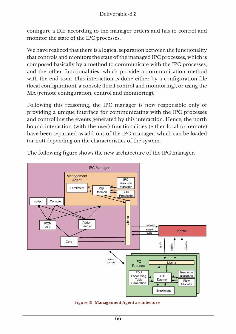
Deliverable-5.3
66
configure a DIF according to the manager orders and has to control andmonitor the state of the IPC processes.
We have realized that there is a logical separation between the functionalitythat controls and monitors the state of the managed IPC processes, which iscomposed basically by a method to communicate with the IPC processes,and the other functionalities, which provide a communication methodwith the end user. This interaction is done either by a configuration file(local configuration), a console (local control and monitoring), or using theMA (remote configuration, control and monitoring).
Following this reasoning, the IPC manager is now responsible only ofproviding a unique interface for communicating with the IPC processesand controlling the events generated by this interaction. Hence, the northbound interaction (with the user) functionalities (either local or remote)have been separated as add-ons of the IPC manager, which can be loaded(or not) depending on the characteristics of the system.
The following figure shows the new architecture of the IPC manager.
Figure 31. Management Agent architecture

Deliverable-5.3
67
4.2. Low level implementation
Several implementation improvements and decisions have been carriedout since D5.2. The most important criterion that have lead to thesemodifications are (ordered by priority):
1. Achievement of the requirements.
2. Accommodation in the RINA theory and in the developed specifications(D5.2)
3. Re-usability of the code for future functionalities.
4. Scalability.
5. Minimization of changes in the already developed modules of theIRATI stack (to maximise code reuse).
The most important implementation decisions are explained in thefollowing subsections.
4.2.1. MA as an IPCM Addon
There are two choices of direction regarding implementation ManagementAgent (MA):
• develop it as a separate daemon process,
• develop it as a module (an internal software component) of the IPCmanager process.
Both options meet the first 4 criteria. However, there are still somesignificant differences between them.
If the MA is developed as a separate daemon, a method to exchangeinformation between the IPC manager and the MA will need to beimplemented. The preferred method for inter-process communications inthe IRATI stack is Netlink[rfc3549], although there are other possibilities.
If the MA is developed as an IPCM module, the MA and the IPC managershare the same address space, so no inter-process communication methodwill be needed. On the other side, the development of the MA as a

Deliverable-5.3
68
module implies some minor changes in the architecture as explained in theprevious subsection. It also implies that there is only one MA per node 3 .
We have decided to implement the MA as a module of the IPC managerbecause of the many functionalities are in common between the twomodules. To allow a proper initialization of IPCM modules (addons), acommand line switch has been added to the IPC manager program toindicate which addons have to be loaded. Since the MA is still at itsinception, the corresponding module is not loaded by default on IPCmanager startup - it is only loaded if explicitly asked to do so. This defaultbehaviour is likely to change in future WP5 releases, when the wholeManagement system will improve and gain functionality, supersedingthe IPC manager configuration file as the primary/preferred RINA nodeconfiguration infrastructure.
In addition to the MA addon, two already existing IPCM functionalitieshave been turned into addons, so that they can be made optional:
• The console component, which provides a CLI interface to the IPCmanager functionalities. On some very simple systems, the IPC managerfunctions will be accessed by the MA only (and hence by the Manager).Consequently the console may not be needed. For the time being,however, the console addon is loaded by default and is there to supportlocal testing/debugging.
• The script component is in charge of realising the configurationspecified by the IPC manager configuration file. This addon is loaded bydefault. The IPC Manager needs certain local configuration to bootstrapitself with the bare minimum to enroll the MA to the management DIF.
4.2.2. Delegation of the RIB
The RIB of the MA is composed by the aggregation of the RIBs of themanaged IPC processes, plus the MA’s own RIB (see [D52] section 5). Toimplement this delegation, there were two possibilities:
• The MA maintains and synchronize both its own RIB and the RIBs of themanaged IPC processes. In this case the MA can respond immediately onthe Manager when the latter accesses the RIB of a managed IPC process.
3The current IRATI/PRISTINE prototype only allows a single IPC Manager per node.However, RINA theory allows more than one IPC Manager per node.

Deliverable-5.3
69
On the other side, a synchronization method is needed between IPCProcesses and MA, so that the MA can update the IPC processes' RIBsin order to reflect the updated internal state of the corresponding IPCprocess. In the IRATI stack the IPCPs are separate OS processes, eachwith its own virtual address space. This supports the implementationapproach of using RIB delegation 4 .
• The MA maintains and synchronize its own RIB, but delegates to themanaged IPC processes all the RIB accesses destined to their RIBS. Inthis case the MA acts as a simple forwarder for the request/response RIBtransaction. A drawback of this solution is that the MA cannot respondimmediately to the Manager request, because it has to wait for thedelegated IPC process to respond.
• The MA will support aggregated values that are a function of RIB datain more than one IPCP.
4.2.3. RIB and CDAP updates
For PRISTINE, a new version of librina-RIB and librina-CDAP librarieshave been developed. The old IRATI version, lacks a proper versioningmechanism and a scheme that allows multiple RIB versions to co-habitatein the same system.
However, things have improved with the inclusion of the MA, since an MAcan communicate to different IPC processes in different DIFs. The RIBs forthese different DIFs can evolve and potentially use different RIB versions.In this new enhanced version, multiple schemes (one for each RIB version)can be defined and filled with RIB objects.
We have also taken advantage of the need of a complete restructuringof the RIB library to separate the CDAP implementation from the RIBimplementation. The manager, or any other application, can use anotherpersistence technology 5 in its (DAF) RIB implementation if it desires,rather than the one selected for the MA.
The decoupled version also exposes less internal details on its interface(cleaner) and therefore it is easier to reuse. The re-factor has also given
4An alternative implementation may have a single RIB for (all IPCPs on) the processingsystem maintained by the MA.5For example, using a clustered object database, or a persisted event stream.

Deliverable-5.3
70
the possibility to fix some low level architectural problems of these twolibraries.
4.2.4. Connecting the MA with the manager
In PRISTINE’s scope, a single manager is able to manage many MAs (1-to-Nrelationship). Two different flows must therefore be allocated between theManager and each agent, one for management commands and one flowfor reporting notifications 6. In practice it must be decided who establishesthese flows, e.g. which endpoint is the initiator and starts the flow allocation.
In order to reduce the MA/Manager configuration, it has been decidedthat the MA initiates the flow allocation (and CACE) procedure towards theManager. However, the implementation has been designed to allow eitherendpoint to request a flow to the other one.
4.3. State of the implementation
In order to improve the effectiveness and timeliness of the MAdevelopment process, we have partitioned the planned MA functionalitiesinto 3 phases, each one composed of various sprints.
1. Phase 1: Creation of the MA. At the end of this phase the MA will beable to:
a. allocate a flow an establish an application connection with theManager.
b. receive CDAP operations to its RIB.
c. create an IPC process from a remote RIB operation.
d. return the RIB state of an IPC process in response to a remote readrequest.
2. Phase 2: Delegation of the IPC processes sub-RIB. At the end of thisphase, the MA will be able to:
a. Delegate any CDAP operation targeting an IPC process RIB object(except for creation and deletion) to the involved IPC process.
6There is a significant difference in the QoS parameters used in these flows (one requiresin-order - reliable delivery, the other tolerates out of order, unreliable delivery), justifyingthe need for both flows.

Deliverable-5.3
71
b. Implement the functionalities defined in D5.2 required by theManager.
3. Phase 3: Notification system. At the end of this phase, the MA will beable to to:
a. Receive any modification or other events taking place in the IPCprocesses RIBs.
b. Group and filter these events.
c. Create notification reports and send to the Manager if needed.
Phase 1 has been successfully completed, and phase 2 is under activedevelopment. The next subsection report on the requirements met by thefirst phase.
4.3.1. Requirements achieved
In [D52], the MA workflow, architecture and component description isexposed. From this description, several requirements have been extracted.The following list briefly explain how those requirements have been metby the current implementation.
Req-JOIN-1The IPC Manager Daemon, at the behest of MA, needs to create all theIPC Processes required to allow the MA to join the DMS-DAF. Thereforeit needs to know a minimal configuration of these IPC Processes.
Addressed byThe script addon of the IPC manager is able to load a configurationfile with all the instructions and information needed to create these IPCProcesses.
Req-JOIN-2The MA needs to know the name of the Manager process
Addressed byA new optional section has been created in the IPC managerconfiguration file to load the name of the Manager and the name of theDIF used to communicate with it.
Req-JOIN-3The MA needs to be able to establish application connectionswith Manager AP(s), optionally authenticating (CACEP component with
Deliverable-5.3
72
authentication policy). For a successful authentication the MA needs tohave the proper credentials prior to contacting the Manager.
Addressed byA CACEP component has been created in the MA which allows theMA and the Manager to establish an application connection. Currently,authentication has not been included. An authentication module isbeing developed in librina, under the WP2 scope, and will be reused inthe MA.
Req-JOIN-4The MA needs to be able to exchange CDAP messages with the Manager(CDAP library component), who will operate remotely on the MA RIB (RIBand RIB Daemon components)
Addressed byCDAP librina library has been refactored so that it is possible to use it asa stand-alone library (decoupled from the RIB library) - by the Manager.On the other side the MA can seamlessly use the CDAP library via theRIB Daemon.
Req-JOIN-5The MA needs to be able to successfully carry out the actions defined inthe DMS-DAF Enrollment specification (Enrollment Task component)
Addressed byThe enrollment specification has been implemented in this version ofthe MA, which allows it to enroll with the Manager.
Req-JOIN-6The MA may need to be able to encrypt the SDUs it sends through anN-1 flow (SDU Protection component)
Addressed byIn this version of the MA, encryption is still not implemented. SDUProtection module is being developed in the scope of WP2 and we planto reuse its methods for the MA.
Req-PROCREQ-1The MA needs to be able to request to the IPC Manager Daemon thecreation and destruction of IPC Process Daemons, and to get the resultof those operations

Deliverable-5.3
73
Addressed byThe Manager is able to send a create CDAP message to the MA targetingthe IPCProcess RIB object which results in the creation of a new IPCprocess.
Req-PROCREQ-2The MA needs to be able to request operations on the RIB of the IPCProcess Daemons in the processing system, and to get the result of thoseoperations
Addressed byCurrently, it is still not possible to request operations on the RIB of theIPC Process - the delegation of the IPC Processes' RIB is under activedevelopment. To be able to simulate a read on the IPC process RIB (anoperation required in the phase 1), we have created a RIB object underevery IPCProcess RIB object in the MA, which responds to a read CDAPoperation with the information of the RIB of such IPC process (queryRIB operation).

Deliverable-5.3
74
5. Validation
The integration plan for the DMS manager and management agent (asoutlined in [D61]) calls for a simple linear integration:
1. Manager (Strategy provision and test)
2. Manager + PRISTINE Strategies
3. Manager + Strategies + Management Agent
To facilitate some parallel testing a (testing) manager in C++ has be createdto allow CDAP functionality testing of the agent.
1. Manager(testing) + Management Agent
The next sections outline the requirements on the default policy set, a setof management strategies, the scenario used and a procedure to validatethe operation of DMS.
5.1. Default policy set
For the most part the default set of policies is sufficient to supportmanagement traffic over the NMS-DAF. However, a least tow types ofQoSCubes will need to be supported:
a. CDAP commands, where the flow is bidirectional (between Managerand Management Agent), ie. responses are expected for mostcommands, therefore the same QoS Cube applies in both directions.Key requirements are: reliable retransmission (EFCP policy), witha guaranteed bandwidth (Resource allocation, DTP policies) anddisconnect notifications (DTCP policy)
b. CDAP notifications, where the flow is unidirectional (from ManagementAgent to Manager).Key requirements are: reliable retransmission (EFCP policy), witha looser set of bandwidth, latency and jitter parameters (Resourceallocation: QoS policies), and ideally whatever-cast routing support(Addressing, NamespaceManagement policies).
The CDAP command QoS cube will also be used for RIB synchronisation,for example, new neighbour announcements.

Deliverable-5.3
75
5.2. Three node validation scenario
The following figure shows the validation scenario used.
Figure 32. DMS validation scenario
The workflow used for this scenario is as follows:
1. The three nodes bootstrap and load all the needed DIF configurationsfrom a configuration file. Therefore, the shim-TCP IPC process, theshim Ethernet IPC process and the normal NMS IPC process arecreated. All these operations are carried out by means of the scriptingadd-on and an appropriate configuration file.
2. The MAs of the three nodes are loaded and started waiting for theManager registration.
3. The Manager registers to the NMS DIF, which causes all the MAs toallocate a flow using the NMS DIF and to establish an applicationconnection to the Manager.
4. The Manager sends a CDAP create message targeting a new IPC processobject in the RIB of node 2. In this single message, there is enough

Deliverable-5.3
76
information for creating the IPC process, assigning it to the normal DIFand registering it to the shim Ethernet DIF.
5. The MA of node 2 receives this message, creates the IPCProcess RIBobject, creates the IPC process using the IPC manager, assigns it to thenormal DIF, registers it to the shim Ethernet DIF and responds to theManager.
6. The manager reads the response, and if the creation of the IPC processhas been successful, it does the same procedure with the node 1. In thiscase, the CDAP message contains enough information to create the IPCprocess and to enroll it to the normal DIF using the already created IPCprocess in the node 2.
7. If the creation and enrollment of the IPC process in the node 1 has beensuccessful, the same procedure is repeated for the node 3.
8. After the reception of the response message of node 3, the Managersends a CDAP read message over the RIBDaemon RIB object under therecently created IPC processes.
9. The MAs receive the read request and respond to the manager with theresult of the IPC manager query rib operation, which is the informationof the objects contained in the RIB of the IPC process.
A limited (mock-up) Manager have been developed only for testingpurposes and has been to validate the achievement of the phase 1 agentobjectives, as explained in Section 4.3.1.
5.3. Strategies used for validation
The strategies below give an insight into the type of management activities[D52] necessary for DMS operation. The following management strategiesare needed, which correspond to generic use-cases for the DMS system.
1. shimipcp.CreationStrategy. This strategy is unique as the shim IPCPprovides no QoS classes, multiplexing support or EFCP mechanisms.A shim-IPC is a thin IPC layer over the existing VLAN or Ethernetfunctionalities.
2. normalipcp.CreationStrategy. This strategy is used to support two generaltypes of flows, outlined above. In general, these are referred to a "CDAPcommand flow" and a "CDAP notification flow".

Deliverable-5.3
77
3. normalipcp.DestructionStrategy. This strategy is used to destroy normal-IPC Processes. However, from the manager viewpoint the CDAPcommands are equivalent for shim-IPC Process destruction.
4. managementagent.MonitoringStrategy. This strategy is a delegationstrategy where the CDAP actions are issued by the sub-strategies. Forexample, to monitor a threshold value several sub-strategies may beemployed depending on the exact context:
a. An EventForwardingDiscriminator(EFD) may need to be created
⇒ maEFD.CreationStrategy (CDAP READ (EFDs), CDAP CREATE(EFD))
b. Or an existing EventForwardingDiscriminator adjusted
⇒ maEFD.AdjustmentStrategy, (CDAP READ (EFD old filter), CDAPSTOP (EFD notifications), CDAP WRITE (new filter), CDAP START(EFD notifications))
c. Or removed (as per adjusted unless the filter expression becomesempty)
⇒ maEFD.DestructionStrategy (CDAP STOP (EFD), CDAP DELETE(EFD))

Deliverable-5.3
78
6. Future plansIn this section we present the next steps to be implemented and tested in theforthcoming work. These will be developed and tested (unit testing) withinWP5 during the second phase of the project. Then, WP6 will integrate themin the use case software bundles and extract results from the respectivetrials.
6.1. Monitoring
[D51] and [D52] describe the overview of the RINA approach with regardsthe monitoring strategies within the DIF Management System. Thedifferent monitoring strategies (reactive, proactive or a hybrid mix) arediscussed in [D52].
Focusing on RINA, there are two information transfer domains that haveto be addressed:
• Information transfer from the Kernel Space to the User Space within asystem. I.e. making available low level kernel information (network stats,CPU usage, etc.) to the processes in the User Space, i.e. the ManagementAgent or other IPC processes.
• Information transfer from the Management Agent to the centralManager. By means of notifications, the Management Agentcommunicates to the Manager information with regards thecorresponding events the Manager is subscribed to.
6.1.1. Steps toward the RINA monitoring approach
To achieve a complete and efficient monitoring approach for PRISTINE,we will focus on the following steps to produce a valuable monitoringsolution to be trialled in WP6.
Kernel Space to Management Agent
1. Determine the system by which the information is exposed from theKernel Space to the User Space processes. The immediate approachis to store the data in the corresponding IPCP RIB, but as the RIB isconstantly evolving, this presents an issue when integrating the differentimplementations. To overcome this issue, an intermediate solution canbe considered to ease the exposure of the Kernel data to the User

Deliverable-5.3
79
Space. A practical approach is to consider the Sys File System (sysfs)provided by the Linux kernel, which is a virtual file system that exportsinformation from kernel subsystems, hardware devices and associateddevice drivers to the user space. This solution shall be further explored.
2. As a follow-up step of the previous point, an approach to reflect themonitored Kernel information in the corresponding IPCP RIB shall bedetermined. Two possibilities are present:
a. to take advantage of the previous solution and populate the RIB withthe information from the Sys File System, or
b. to develop a different solution to write the monitored Kernelinformation in the RIB (e.g. by means of System Calls).
Management Agent to the DMS Manager
1. Define an efficient and scalable monitoring approach for thenotifications between the Management Agent and the Manager. To thatend, an event-based monitoring approach is envisaged to be designedand implemented in both the Management Agent and the Manager. Themonitoring accuracy is inversely proportional to the involved signalingload and a trade-off must be studied. In general terms, the Manager willconfigure the Manager Agent monitoring policies in a dynamic fashionto maintain a low network load while minimizing the accuracy loses.This shall also be further studied.
Data processing is also a relevant aspect to be considered. There is a carefulbalance required here between raw and processed data that needs to beconsidered. Processing data at the Agent has two negatives:
a. overhead, the primary job of the Network Element is not monitoring;and
b. the processed data may mask a problem from the manager.
Sending data that is more raw, the manager can always find out what ishappening (volume overhead here vs putting a new policy in place duringa crisis). In contrast, sending computed metrics may mask what is reallygoing on. Also, an important aspect is timeliness. The MA may record rawdata for later uploading, so that situations can be analyzed after the fact.This data will not only be used for monitoring the performance of thenetwork but for diagnosing problems as well.

Deliverable-5.3
80
6.1.2. Policies involved
Apart from the DIF Management System (Manager Agent and Manager),the RINA components and policies that are involved in the monitoringprocesses are the following:
Policies that are intended to provide monitoring information
• Relaying an Multi-plexing Task
◦ Max. queue policy. This policy will indicate when the queues reachthe maximum buffering capacity.
◦ Monitoring policy. This policy will monitor scheduling aspects of theRelaying an Multi-plexing Task.
Policies that are intended to use monitoring information
• Resource Allocator
◦ Forwarding table generator policy. This policy will use the monitoredload of the N-1 DIFs to create the PDU forwarding table in the case ofthe Dynamic QoS-aware multi-path routing.
6.2. Management Agent and RINA stack
Some improvements on the Management Agent and RINA stack side arenecessary. These have been previously discussed so a short list is given here.
1. Completion of the ongoing work on the delegation of the IPC processessub-RIB.
2. Improvements to librina. For example, improving the scalability of theAPI for RINA applications (and by extension the DMS Manager)
3. Implementation of the notification system (as specified in previoussection), which will allow the DMS Manager to configure notifications.
6.3. DMS Manager
The described functionality of the DMS Manager (event DSLs, RIB Model,RIB Model Code Generator, Strategy Framework, DMS Manager) is stableand tested. Future plans focus first on the extension of the describedsoftware system to ease the creation and deployment of strategies as wellas to allow for multiple RIB models to be defined in the same code base.

Deliverable-5.3
81
1. Add an abstract schema for Strategy assembly and provide an XML aswell as a JSON concrete schema. The content of the abstract schema willbe identical to the current manual assembly.
2. Add an automated mechanism for the assembly of Strategies to theexisting manual (implementation) using the concrete XML and JSONschemas
3. Add an abstract schema for Strategy deployment and provide an XMLas well as a JOSN concrete schema. The content of the abstract schemawill be identical to the CLI commands currently being used.
4. Add an automated deployment using the concrete XML and JSONschemas in addition to the current CLI deployment method.
5. Add an OODA implementation that fully uses the DMS-ES generic statemachine.
6. If required, add an ECA implementation for strategies to demonstratea second management policy model.
7. Provide a DIF-Viz component that can visualise DIFs based on actualRIB runtime information.
8. Validate the monitoring solution to allow dynamic notification filtering.
9. Continue work on the CDAP connector and align with librina APIchanges.

Deliverable-5.3
82
References[asciidoc] Stuart Rackham. Text based document generation. Available
online7 .
[adoctor15] Asciidoctor, The Asciidoctor Maven plugin, Available online8 .
[boyd96] Boyd, J.R., The Essence of Winning and Losing. Lecture notes,June, 1996. Available online9 .
[D51] PRISTINE Consortium. Deliverable D5.1. Draft specification ofcommon elements of the management framework. June 2014.Available online10 .
[D52] PRISTINE Consortium. Deliverable D5.2. Specification of commonelements of the management framework. December 2014. Availableonline11 .
[D61] PRISTINE Consortium. Deliverable D6.1. First iteration trials planfor System-level integration and validation. April 2015. Availableonline12 .
[fowler05] Martin Fowler. Event Sourcing. Web blog, December 2005.Available online13 .
[json-s] Internet Engineering Task Force (IETF). JSON Schema: core.January 2013. Available online14 .
[M3010] ITU-T. M.3010 : Principles for a telecommunicationsmanagement network. February 2000. Available online15 . ] InternetEngineering Task Force (IETF). Introduction and Applicability
7 http://www.asciidoc.org8 http://asciidoctor.org/docs/asciidoctor-maven-plugin/9 https://fasttransients.files.wordpress.com/2010/03/essence_of_winning_losing.pdf10 http://ict-pristine.eu/wp-content/uploads/2013/12/pristine_d51-common-management-elements_draft.pdf11 http://ict-pristine.eu/wp-content/uploads/2013/12/pristine-d52-draft.pdf12 http://ict-pristine.eu/13 http://martinfowler.com/eaaDev/EventSourcing.html14 http://tools.ietf.org/html/draft-zyp-json-schema-0415 https://www.itu.int/rec/T-REC-M.3010/en
Deliverable-5.3
83
Statements for Internet Standard Management Framework. IETFRFC 3410, December 2002.
[rfc3549] Internet Engineering Task Force (IETF). Linux Netlink as an IPServices Protocol. IETF RFC 3549, July 2003. Available online16 .
[rfc6455] Internet Engineering Task Force (IETF). The Websocket protocol.IETF RFC 6455, December 2011. Available online17 .
[S101] Structure 101. Available online18 .
[X700] ITU-T. X.700 : Management framework for Open SystemsInterconnection (OSI) for CCITT applications. September 1992.Available online19 .
16 http://tools.ietf.org/html/rfc354917 https://tools.ietf.org/html/rfc645518 http://www.structure101.com19 https://www.itu.int/rec/T-REC-X.700/en