delft university of technology multi-objective
TRANSCRIPT

Delft University of Technology
Multi-objective optimization of laminated composite beam structures using NSGA-IIalgorithm
Vo-Duy, T.; Duong-Gia, D.; Ho-Huu, V.; Vu-Do, H. C.; Nguyen-Thoi, T.
DOI10.1016/j.compstruct.2017.02.038Publication date2017Document VersionAccepted author manuscriptPublished inComposite Structures
Citation (APA)Vo-Duy, T., Duong-Gia, D., Ho-Huu, V., Vu-Do, H. C., & Nguyen-Thoi, T. (2017). Multi-objectiveoptimization of laminated composite beam structures using NSGA-II algorithm. Composite Structures, 168,498-509. https://doi.org/10.1016/j.compstruct.2017.02.038
Important noteTo cite this publication, please use the final published version (if applicable).Please check the document version above.
CopyrightOther than for strictly personal use, it is not permitted to download, forward or distribute the text or part of it, without the consentof the author(s) and/or copyright holder(s), unless the work is under an open content license such as Creative Commons.
Takedown policyPlease contact us and provide details if you believe this document breaches copyrights.We will remove access to the work immediately and investigate your claim.
This work is downloaded from Delft University of Technology.For technical reasons the number of authors shown on this cover page is limited to a maximum of 10.
Multi-objective optimization of laminated composite beam
structures using NSGA-II algorithm
T. Vo-Duy1,2
, D. Duong-Gia1,2
, V. Ho-Huu3, H.C. Vu-Do
1,2, T. Nguyen-Thoi
1,2,*
1Division of Computational Mathematics and Engineering, Institute for Computational Science, Ton
Duc Thang University, Ho Chi Minh City, Vietnam 2Faculty of Civil Engineering, Ton Duc Thang University, Ho Chi Minh City, Vietnam
3Faculty of Aerospace Engineering, Delft University of Technology, Delft, The Netherlands
E-mail addresses: [email protected] (T. Vo-Duy); [email protected] (D. Duong-Gia);
[email protected] (V. Ho-Huu); [email protected] (H.C. Vu-Do);
[email protected] (T. Nguyen-Thoi)
Abstract
The paper deals with the multi-objective optimization problem of laminated composite beam
structures. The objective function is to minimize the weight of the whole laminated
composite beam and maximize the natural frequency. The design variables include fiber
volume fractions, thickness and fiber orientation angles of layers, in which the fiber volume
fractions are taken as continuous design variables with the constraint on manufacturing
process while the thickness and fiber orientation angles are considered as discrete variables.
The beam structure is subject to the constraint in the natural frequency which must be greater
than or equal to a predetermined frequency. For free vibration analysis of the structure, the
finite element method is used with the two-node Bernoulli-Euler beam element. For solving
the multi-objective optimization problem, the nondominated sorting genetic algorithm II
(NSGA-II) is employed. The reliability and effectiveness of the proposed approach are
demonstrated through three numerical examples by comparing the current results with those
of previous studies in the literature.
Keywords: Multi-objective optimization, laminated composite beam, nondominated sorting
genetic algorithm II (NSGA-II), fiber volume fraction, frequency constraint.
*Corresponding author. Tel.: +84 933 666 226
E-mail addresses: [email protected] (Trung Nguyen-Thoi)
© 2017 Manuscript version made available under CC-BY-NC-ND 4.0 license https://creativecommons.org/licenses/by-nc-nd/4.0/ Post print in : Composite StructuresVolume 168, 15 May 2017, Pages 498–509Link to formal publication (Elsevier): http://dx.doi.org/10.1016/j.compstruct.2017.02.038

1. Introduction
Due to various exceptional advantages, composite structures have been widely used
in automotive industries, civil infrastructures, and aerospace structures, especially in aircraft
and a lot of other engineering applications. One of the primary advantages of composite
structures is smaller weight density in comparison with metallic structures. In addition, some
composite structures also provide better stiffness compared to metallic structures.
Beyond such the advantages, the effective use of composite structures also depends
significantly on an optimal design which is the result of solving the single-objective or
multi-objective optimization problems with either the lowest weight or the maximum
stiffness (for the single-objective cases), or both of them (for the multi-objective cases).
However, for the case of laminated composite structures, the optimization design
procedure is usually more complex than those associated with isotropic material
structures. This is because there is a large number of involved variables and the
intrinsic anisotropy behavior of the individual layers in the laminated composite
structures [1]. As a result, although there have been a lot of related studies published in
the literature, design optimization for laminated composite structures has been still a matter
of current research.
Over several decades, the study on design optimization for laminated composite
structures like beams and plates is preferred and has attracted a certain attention from many
researchers around the world. A lot of these previous studies focused on single-
objective optimization in which the fitness functions are usually maximizing fundamental
frequency [2–7], or maximizing buckling load [8–13], or maximizing strain energy/stress
[14–17], or minimizing weight [18–20], or topology optimization [21,22] while design
variables are frequently fiber orientation angles, fiber distribution and thickness of layers.
Recently, Liu [23,24] and Vo-Duy et al. [25] presented a new approach for the
lightweight design optimization of laminated composite beams and plates. In this
approach, the fiber volume fractions of the layers are considered as design variables.
Also, the frequency constraint is taken into account. According to the numerical
results in these studies, the fiber volume factions of the layers shown their significant
influence on the weight of the laminated composite structures. However, their studies
were limited to a single objective, the weight of the laminated structures. Moreover,
the design variables in these studies were just focused on either the fiber volume fractions
of the layers in Refs. [23,24] or both fiber volume fractions of the layers and the thickness of
the layers in Ref. [25].

On the other hand, there have also been some papers conducted for multi-objective
optimization of laminated composite structures. For example, Pelletier and Vel [26] studied
the multi-objective optimization of fiber reinforced composite materials. Two models with
conflicting objectives were carried out in this study. In the first model problem, the objective
functions were to maximize the failure load and minimize the mass of a graphite/epoxy
laminate subjected to the constraint of biaxial moments. In the second model problem,
objective functions were to maximize the hoop rigidity and axial rigidity and minimize the
mass of a graphite/epoxy cylindrical pressure vessel subjected to the constraint of the failure
pressure which must be greater than a prescribed value. For both models, fiber orientation
angles and fiber volume fractions were taken as design variables. In another study, Lee et al.
[27] presented a work which aimed to minimize the weight of multilayered composite plates
and minimize their maximum displacement. The design variables include the type of fiber,
thickness and the fiber orientations of each layer. Vosoughi and Nikoo [28] developed a
hybrid method for the maximizing fundamental natural frequency and thermal buckling
temperature of laminated composite plates. Only fiber orientation angles are treated as design
variables in this study. Recently, Honda et al. [29] examined the trade-off solutions between
the mechanical performance and curvatures of reinforcing fibers of laminated composite
plates via two conflicting objectives. One is to maximize the fundamental frequency or Tsai-
Wu failure criteria and the other is to minimize the curvature of the curvilinear fibers. In this
work, the design variables are the coefficients of the shape of the curvilinear fibers.
So far in a general view, it can be seen from the literature that most of the studies related
to multi-objective optimization of laminated composite structures focused on considering the
optimal solutions related to minimal weight and static characteristic of the structures, and the
design variables are either the thickness or fiber volume fraction that are integrated with the
fiber orientation angles. There are a few papers, where the trade-off relationship between the
weight and the frequency of the laminated composite beams are studied. Moreover, the
simultaneous use of all the fiber volume fractions, thickness and fiber orientation angles of
layers for multi-objective optimization of laminated composite structures is somewhat still
limited.
Under such mentioned research gaps for the multi-objective optimization of laminated
composite beam structures and motivated by the studies of Liu [23,24] and our previous work
[25] on lightweight design of laminated composite beams and plates under frequency
constraint, the present paper hence deals with the multi-objective optimization of laminated
composite beams for minimizing the weight of the whole laminated composite beam and

maximizing its natural frequency. The design variables are fiber volume fractions, thickness
and fiber orientation angles of layers in which the fiber volume fractions are taken as
continuous design variables with the constraint on manufacturing process while the thickness
and fiber orientation angles are considered as discrete variables. The beam structure is subject
to the constraint in the natural frequency which must be greater than or equal to a
predetermined frequency. For free vibration analysis of the structure, the finite element
method is used with the two-node Bernoulli-Euler beam element. For solving the multi-
objective optimization problem, the nondominated sorting genetic algorithm II (NSGA-II)
[30] is employed. Three numerical examples are implemented with the presence of Pareto
optimal solution set. In addition, the present results are also compared with those of previous
study in the literature to demonstrate the reliability and effectiveness of the proposed
approach.
The remainder of the paper is organized as follows. Section 2 summarizes the governing
equations related to free vibration analysis of the laminated composite beam. Section 3
formulates the multi-objective optimization problem for laminated composite beams. Section
4 briefly presents the NSGA-II algorithm. Section 5 examines some numerical examples, and
Section 6 draws some conclusions.
2. Free vibration of laminated composite beams
Consider a laminated composite beam consisting of N layers. The size of the beam is
characterized by the length L, the width b and the thickness h. A global coordinate system
Oxyz is attached at the center of the beam such that the x-axis is in the longitudinal direction,
as shown in Figure 1. Here the bending of the beam on the yz-plane is not considered. In each
layer, we denote the fiber orientation angles by θ(1)
, θ(2)
, θ(3)
,...., θ(N)
, the fiber volume
fractions by 1
fr , 2
fr ,..., N
fr and vertical coordinates of layers by z0, z1,..., zN-1, zN.
Based on a classical beam theory (CBT) or Euler Bernoulli (EB) beam theory where the
influence of shear deformation and rotary inertia can be ignored, the displacement field of the
laminated composite beam is given by
0
( , ) ( )
( , ) ( )
xu x z z x
w x z w x
(1)
where u and w are x-direction and z-direction displacements of the beam respectively; x is
the rotation of the cross section and determined by x
w
x
; and w0 is the z-direction
displacement of the beam neutral axis.
Figure 1. A laminated composite beam.
The relationship between the displacement and strain is expressed by 2
2x
u wz
x x
.
Then the stress-strain equations for an element of material in the kth lamina may be written as
( ) ( )
11
k k
x xQ (2)
where
( )
( ) 4 ( ) ( ) ( ) 2 ( ) 2 ( ) ( ) 4 ( )
11 12 66 2211cos 2 2 sin cos sin
kk k k k k k k kQ Q Q Q Q (3)
with
( ) ( ) ( )( ) ( ) ( ) ( ) ( )1 12 2 211 12 66 12 22( ) ( ) ( ) ( ) ( ) ( )
12 21 12 21 12 21
, , ,1 1 1
k k kk k k k k
k k k k k k
E E EQ Q Q G Q
(4)
where ( )
1
kE and ( )
2
kE are longitudinal and transverse elastic moduli, respectively; ( )
12
k and
( )
21
k are Poisson constants; ( )
12
kG is strain modulus. These parameters are calculated as [23,31]
( ) ( ) ( ) ( ) ( )
1 1k k k k k
f f m m f f m fE E r E r E r E r
( )
2 ( ) ( ) ( ) ( )1
f m f mk
k k k kf m m f f f m f
E E E EE
E r E r E r E r
( ) ( ) ( ) ( ) ( ) ( )
12 21 1k k k k k k
f f m m f f m fr r r r (5)
12 ( ) ( ) ( ) ( )1
f m f m
k k k kf m m f f f m f
G G G GG
G r G r G r G r
,
2 12 1
f mf m
mf
E EG G

where Ef is the elastic modulus of fiber; Em is modulus of matrix; f is Poisson constant of
fiber and m is Poisson constant of matrix.
The governing equation for free vibration of the laminated composite beam can be
obtained by using the Hamilton’s principle
(6)
where ( )k is the mass density of the kth layer and expressed as follows
( ) ( ) ( )1k k k
f f f mr r (7)
where ρf and ρm are the density of fiber and matrix, respectively.
Using the finite element method, the overall system equations of motion can be
expressed as
(8)
where d is the nodal displacement vector; is the second-order derivative with respect to
time of d; M and K are the global mass and stiffness matrices which are assembled,
respectively, from elemental stiffness matrix (Ke) and elemental mass matrix (M
e), given by
2 2 2 2
111
3
2 2
12 6 12 6 156 22 54 13
4 6 2 4 13 3;
12 6 156 22420
sym. 4 sym. 4
e e e e
e e e e e ee e e
e ee
e e
l l l l
l l l l l lI lD
l ll
l l
K M (9)
where le is the length of the eth element and D11 and I1 are defined by
( )
3 3 ( )
11 1 1 111
0 0
1;
3
N Nk
k
k k k k
k k
D bQ z z I b z z
(10)
The natural frequency ω and mode shape f of the beam are obtained by solving the
eigenvalue problem which is derived from Equation (8) as follows
(K -w 2M )f = 0 (11)
3. Formulation of the multi-objective optimization problem
In this study, the objective functions of multi-objective optimization problem are to
minimize the weight and maximize the first natural frequency of a laminated composite
beam. The optimization problem has a constraint on the first frequency that must be larger
than a predefined value by designer. The mass of the laminated composite beam is strongly
influenced by thickness and fiber volume fractions of layers while the first frequency of the
laminated composite beam is significantly influenced not only by thickness and fiber volume

fractions, but also by fiber orientation angles of layers. This paper hence considers all
variables including thickness, fiber volume fractions and fiber orientation angles of layers as
design variables. In addition, to investigate in detail, the effect of these variables on the
Pareto-optimal solution, three models with various design variables are suggested for the
multi-objective optimization problem as follows.
+ Model 1: only fiber volume fractions of layers are the design variables:
( ) ( ) ( )
1
1
( ) max
Minimum
Maximum
subject to
0 , 1,...,
Nk k k
f f k
k
f
f
k
f f
mass r A t
freq
freq f
r r k N
r
r
r
(12)
+ Model 2: fiber volume fractions and thickness of layers are the design variables:
( ) ( ) ( )
1
1
( ) max
( )
low up
,
,
subject to ,
0
,
Minimum
1,...,
Maximum
Nk k k
f f k
k
f
f
k
f f
k
mass r A t
freq
freq f
r r
t t t k N
r t
r t
r t(13)
+ Model 3: fiber volume fractions, thickness and fiber orientation angles of layers are the
design variables:
(14)
where ,fmass r t and ,ffreq r t are the mass and first frequency of the beam,
respectively; fr , t, θ are the design variable vectors of fiber volume fractions
( )k
fr , thickness
( )kt and fiber orientation angle θ(k)
of layers, respectively; ( ) ( ) k k
fr and kA are the mass

density and the area of the kth layer, respectively; 1f is the lower bound of the first
frequency; lowt and upt are respectively the lower and upper bounds of ( )kt ; N is the total
number of layers; and max
fr is the maximum of fr in a lamina. In manufacturing, it should be
noted that the maximum value of rf depends on the arrangement of fiber in the matrix. As
mentioned in references [31,32], the value of max
fr can be either 0.7854 if the fiber
arrangement is a square array as described in Figure 2a or 0.9069 if the fiber arrangement is a
hexagonal array as shown in Figure 2b.
(a) (b)
Figure 2. Fiber arrangements. (a) Square array; (b) Hexagonal array.
4. NSGA-II algorithm
Unlike the single-objective optimization problem which provides only a single optimal
solution, the multi-objective optimization problem will provide a set of points known as
Pareto optimal set which represents the trade-off solutions between conflicting objectives. To
obtain the Pareto-optimal solutions, a number of techniques have been proposed in the
literature [33] in which the multi-objective evolutionary algorithms (MOEAs) such as
NSGA-II [30], SPEA-II [34], and MOEA/D [35] gained much attention from the researchers
due to their effectiveness and easy implementation. Among these attended MOEAs,
the NSGA-II is considered as one of the most powerful methods. This algorithm is an
improved version of NSGA [36] developed from the well-known genetic algorithm ([37–40])
and non-dominated sorting concept by Goldberg [41]. In the past decade, the NSGA-II
has been improved and widely applied in design optimization of various problems (see, for
example,
references [42–45]) and also in design optimization of laminated composite plate structures
[26,29]. In this paper, the NSGA-II algorithm is used to solve a the multi-objective
optimization problem related to the laminated composite beam presented in section 3.
The brief description of the algorithm is presented below.
(1) Generate an initial population P0 with N solutions is randomly.
(2) Create an offspring population Qt using binary tournament selection based on
crowding-comparison operator, crossover and mutation performed on the parent
population (Pt), where subscript “t” denotes the number of generations. The
offspring population and its parent population are then combined to produce the
entire population Rt.
(3) Perform a fast nondominated sorting approach on the entire population Rt to identify
different nondominated fronts of objective functions F1, F2, etc.
(4) Create a new parent population (Pt+1) of size N from the obtained fronts (Fi).
(5) Repeat the process until the maximum number of iterations is reached.
For more details of the above procedure, the readers are encouraged to refer to the original
paper [30].
5. Numerical examples
In this section, numerical results of optimal design for a symmetric laminated composite
beam structure are presented. The beam was previously studied by Liu [23] for single-
objective optimization. The geometric parameters of the laminated composite beam are given
by: length L = 14.4 m, width b = 0.3 m and height h = 0.48 m. The beam has the same
number of layers (N = 8) and the same material properties as given by Liu [23], i.e., the fiber
material 294GPafE , 0.2fv , 31.81g/cmf and the matrix material 4.2GPamE ,
0.3mv , 31.24g/cmm . The laminated composite beam has two kinds of fiber orientation
angles which include [00/90
0/45
0/-45
0]S and [45
0/0
0/90
0/-45
0]S.
The optimization problem is investigated with three different models as already
mentioned in Section 3. In all models, the fiber volume fractions of layers are treated as the
continuous design variables and its upper bound, rmax, is set to be 0.9069. In addition, in the
first model, the thickness of layers and fiber orientation angles are fixed and same as those in
[23], i.e, t(k)
= 6 mm (k = 1,...,8) and two kinds of fiber orientation angles including
[00/90
0/45
0/-45
0]S and [45
0/0
0/90
0/-45
0]S. In the second model, the fiber orientation angles of
layers are kept constant similarly as in the first model while thicknesses of layers are treated

as the discrete design variables which are integers in the range of [1, 20] (unit: mm). In the
third model, both thickness and fiber orientation angles of layers are considered as discrete
design variables in which the constraint of thickness the same as considered in the second
model and the fiber orientation angles of layers are integers in the range of [-900, 90
0].
In each model, the optimization problem is conducted with four different boundary
conditions: fixed–fixed, fixed–free, fixed–pinned and pinned–pinned, and the NSGA-II
method is applied with the population size of 50 and maximum number of iterations of 100.
5.1 Solution of frequencies of laminated composite beam using finite element method
The frequencies of the laminated composite beam are determined by using two-
node Bernoulli-Euler beam element. The accuracy and reliability of the programing by this
finite element analysis is demonstrated through the numerical results of the case of [0/90/45/-
45]s laminated composite beam whose fibre volume fractions are rf (k)
= 50% (k = 1, 2, ..., 8).
The beam structure is divided into 16 beam elements of equal lengths. The first four squares
of frequencies (ω2) of the beam with four different boundary conditions are provided in Table
1 in comparison with the analytical solutions. It can be seen from the table an excellent
agreement between results. The results illustrated clearly the high accuracy and reliability of
the numerical analysis for determining the frequencies of the laminated composite beam, and
hence this numerical analysis can be ready to integrate effectively with the NSGA-II for
finding the optimal solutions of the multi-objective optimization problems.
Table 1. The first four frequencies ω2 (Hz
2) of the laminated composite beam.
Boundary
condition Method Mode 1 Mode 2 Mode 3 Mode 4
pinned-pinned Analytical [23] 2862 45,795 231,838 732,722
Present 2862 45,795 231,840 732,746
fixed-fixed Analytical [23] 14,708 111,761 429,514 1,173,680
Present 14,708 111,761 429,522 1,173,740
fixed-free Analytical [23] 363 14,266 111,848 429,503
Present 363 14,266 111,849 429,511
fixed-pinned Analytical [23] 6985 73,355 319,324 933,803
Present 6985 73,355 319,329 933,841

5.2. Solution of multi-objective optimization problem: Model 1
Figures from Figure 3 to Figure 6 show the Pareto-optimal solutions of the laminated
composite beams for different boundary conditions where the horizontal and vertical axes
represent the weight and first frequency, respectively. For each beam and each boundary
condition, the optimal solution corresponding with the lowest frequency is provided in Table
2, Table 3, Table 4 and Table 5 in comparison with the single-objective optimization solution
obtained by Liu [23].
As can be seen from Table 2 to Table 5, the obtained weights by the present approach
are the same as those by Liu [23] in almost cases. A little difference is observed only for the
case of [450/0
0/90
0/-45
0] beam with fixed-free boundary condition. This is because the fiber
volume fraction varies from 0 to 1 in Liu’s study while it varies from 0 to 0.9060 in the
present study which is more accurate as shown in geometrical analysis of Figure 2.
As can be observed in Figures from Figure 3 to Figure 6, the Pareto-optimal curves are
different for two beams having different fiber orientations. Particularly, for the case of
[00/90
0/45
0/-45
0]s beam, the Pareto-optimal solutions are seen to be nearly linear for all four
various boundary conditions. While for the case of [450/0
0/90
0/-45
0]s beam, these curves are
nonlinear for all four various boundary conditions. Also, it can be seen that the best weights
corresponding to the lowest frequency of the case of [450/0
0/90
0/-45
0]s beam are always
greater than those of the case of [00/90
0/45
0/-45
0]s beam.
(a) [00/90
0/45
0/-45
0]s (b) [45
0/0
0/90
0/-45
0]s
Figure 3. Pareto-optimal solutions of fixed–fixed beam for model 1.
00.510
0.51
2650 2700 2750 2800 28501
1.2
1.4
1.6
1.8
2
2.2
2.4
2.6
2.8x 10
4
Fre
quen
cy
Weight
NSGA-II
Liu (2015)
Paper
(2658; 10000)
2700 2800 2900 3000 3100 32001
1.2
1.4
1.6
1.8
2
2.2x 10
4
Fre
qu
ency
Weight
NSGA-II
Liu (2015)
Paper
(2748; 10000)
(a) [00/90
0/45
0/-45
0]s (b) [45
0/0
0/90
0/-45
0]s
Figure 4. Pareto-optimal solutions of fixed–free beam for model 1.
(a) [00/90
0/45
0/-45
0]s (b) [45
0/0
0/90
0/-45
0]s
Figure 5. Pareto-optimal solutions of fixed–pinned beam for model 1.
2720 2740 2760 2780 2800 2820 2840400
450
500
550
600
650
700
Fre
qu
ency
Weight
NSGA-II
Liu (2015)
Paper
(2721; 400)
2900 2950 3000 3050 3100400
420
440
460
480
500
520
540
Fre
qu
ency
Weight
NSGA-II
Liu (2015)
Paper
(2943; 400)
(2914; 400)
2600 2650 2700 2750 2800 28502000
4000
6000
8000
10000
12000
14000
Fre
qu
en
cy
Weight
NSGA-II
Liu (2015)
Paper
(2612; 2500)
2600 2700 2800 2900 3000 3100 32002000
3000
4000
5000
6000
7000
8000
9000
10000
11000
Fre
qu
en
cy
Weight
NSGA-II
(2652; 2500)
Liu (2015)
Paper

(a) [00/90
0/45
0/-45
0]s (b) [45
0/0
0/90
0/-45
0]s
Figure 6. Pareto-optimal solutions of pinned- pinned beam for model 1.
Table 2. Optimal design results of the fixed-fixed beam for model 1
Fibre orientation Method Fiber volume fraction (%) Weight
(kg)
Frequency
(Hz2) (1)
fr (2)
fr (3)
fr (4)
fr
[00/90
0/45
0/-45
0]s
Ref. [23] 29.2 0 0 0 2658 10000
NSGA-II 29.2 0 0 0 2658 10000
[450/0
0/90
0/-45
0]s
Ref. [23] 0 59.9 0 0 2748 10000
NSGA-II 0 60.03 0 0 2748 10000
Table 3. Optimal design results of the fixed–free beam for model 1
Fibre orientation Method Fiber volume fraction (%) Weight
(kg)
Frequency
(Hz2) (1)
fr (2)
fr (3)
fr (4)
fr
[00/90
0/45
0/-45
0]s
Ref. [23] 50.7 0 0 0 2721 400
NSGA-II 50.7 0 0 0 2721 400
[450/0
0/90
0/-45
0]s
Ref. [23] 16 100 0 0 2914 400
NSGA-II 34.95 90.69 0 0 2943 400
Table 4. Optimal design results of the fixed–pinned beam for model 1
Fibre orientation Method Fiber volume fraction (%) Weight
(kg)
Frequency
(Hz2) (1)
fr (2)
fr (3)
fr (4)
fr
[00/90
0/45
0/-45
0]s
Ref. [23] 13.7 0 0 0 2612 2500
NSGA-II 13.8 0 0 0 2612 2500
2550 2600 2650 2700 2750 2800 28500
1000
2000
3000
4000
5000
6000
Fre
qu
en
cy
Weight
NSGA-II
Liu (2015)
Paper
(2582; 400)
2500 2600 2700 2800 2900 3000 31000
500
1000
1500
2000
2500
3000
3500
4000
4500
Fre
qu
ency
Weight
NSGA-II
Liu (2015)
Paper
(2593; 400)

[450/0
0/90
0/-45
0]s Ref. [23] 0 27 0 0 2652 2500
NSGA-II 0 27.6 0 0 2652 2500
Table 5. Optimal design results of the pinned –pinned beam for model 1
Fibre orientation Method Fiber volume fraction (%) Weight
(kg)
Frequency
(Hz2) (1)
fr (2)
fr (3)
fr (4)
fr
[00/90
0/45
0/-45
0]s
Ref. [23] 3.7 0 0 0 2582 400
NSGA-II 4 0 0 0 2582 400
[450/0
0/90
0/-45
0]s
Ref. [23] 0 7.3 0 0 2593 400
NSGA-II 0 7.96 0 0 2593 400
5.3. Solution of multi-objective optimization problem: Model 2
The Pareto-optimal solutions of two laminated composite beams for various boundary
conditions are shown in Figure 7, Figure 8, Figure 9 and Figure 10. For the purpose of
comparison, the corresponding Pareto-optimal solutions in model 1 are also illustrated
simultaneously in these figures. It can be observed from these figures that the Pareto-optimal
solution line in model 2 locates higher than that in model 1. It means that model 2 yields
better results than the model 1. For example, as can be seen in Figure 7a, the weight of
optimal structure in model 2 (1645 kg - design point A) is less than that of the model 1 (2658
kg - design point C) while the frequencies are the same (10000 Hz). Also, in the same mass
(close to 2658kg), model 2 has frequency 26539 Hz (design point B) greater than that of the
model 1 (10000 Hz – design point C). In Figures from Figure 8 to Figure 10, the same results
in comparison are shown.
Tables from Table 6 to Table 9 provide the fiber volume fractions and thickness of the layers
corresponding with design points A, B, C in Figures from Figure 7 to Figure 10. It can be
seen that the total thicknesses in design points A and B are smaller than that in design point
C. In contrast, the fiber volume fractions of each layer of design points A and B are much
larger than that of the design point C.

(a) [00/90
0/45
0/-45
0]s (b) [45
0/0
0/90
0/-45
0]s
Figure 7. Pareto-optimal solutions of fixed–fixed beam for model 2 and model 1
(a) [00/90
0/45
0/-45
0]s (b) [45
0/0
0/90
0/-45
0]s
Figure 8. Pareto-optimal solutions of fixed–free beam for model 2 and model 1.
1600 1800 2000 2200 2400 2600 2800 3000 32001
1.5
2
2.5
3
3.5
4x 10
4
Fre
quen
cy
Weight
Variables: rf
Variables: rf , t
A (1645; 10000)
C (2658; 10000)
B (2649; 26539)
1600 1800 2000 2200 2400 2600 2800 3000 32001
1.5
2
2.5
3
3.5x 10
4
Fre
quen
cy
Weight
Variables: rf
Variables: rf , t
A (1778; 10000)
C (2748; 10000)
C (2741; 24848)
2000 2200 2400 2600 2800 3000 3200400
500
600
700
800
900
1000
Fre
qu
ency
Weight
Variables: rf
Variables: rf , t
A (2071; 400)
C (2721; 400)
B (2728; 682)
2200 2400 2600 2800 3000 3200400
450
500
550
600
650
700
750
800
850
900
Fre
quen
cy
Weight
Variables: rf
Variables: rf , t
A (2200; 400)C (2943; 400)
C (2947; 731)

(a) [00/90
0/45
0/-45
0]s (b) [45
0/0
0/90
0/-45
0]s
Figure 9. Pareto-optimal solutions of fixed–pinned beam for model 2 and model 1.
(a) [00/90
0/45
0/-45
0]s (b) [45
0/0
0/90
0/-45
0]s
Figure 10. Pareto-optimal solutions of pinned- pinned beam for model 2 and model 1.
Table 6. Optimal design results of the laminated composite beams (fixed–fixed) for model 2
Fibre
orientation
Design
variable
Thickness
(mm) Fiber volume fraction (%) Weight
(kg)
Frequency
(Hz2)
t1 t2 t3 t4 (1)
fr (2)
fr (3)
fr (4)
fr
[00/90
0/45
0/-45
0]s
rf (C) 6 6 6 6 29.2 0 0 0 2658 10000
t, rf (A) 6 5 1 1 85.39 0 0 0 1645 10000
t, rf (B) 9 6 4 2 90 0 0 0 2649 26539
1000 1500 2000 2500 3000 35000.2
0.4
0.6
0.8
1
1.2
1.4
1.6
1.8
2x 10
4
Fre
quen
cy
Weight
Variables: rf
Variables: rf , t
A (1227; 2500)
C (2612; 2500)
B (2634; 12294)
1000 1500 2000 2500 3000 35000.2
0.4
0.6
0.8
1
1.2
1.4
1.6
1.8x 10
4
Fre
quen
cy
Weight
Variables: rf
Variables: rf , t
A (1349; 2500)
C (2652; 2500)
B (2641; 10903)
500 1000 1500 2000 2500 3000 35000
1000
2000
3000
4000
5000
6000
7000
8000
Fre
quen
cy
Weight
Variables: rf
Variables: rf , t
B (2583; 4884)
A (762; 400)
C (2582; 400)
500 1000 1500 2000 2500 30000
1000
2000
3000
4000
5000
6000
7000
Fre
qu
ency
Weight
Variables: rf
Variables: rf , t
A (882; 400)
C (2593; 400)
B (2589; 4411)

[450/0
0/90
0/-45
0]s
rf (C) 6 6 6 6 0 60.03 0 0 2748 10000
t, rf (A) 1 6 3 4 18.65 90.69 0 0 1778 10000
t, rf (B) 1 8 5 8 35.86 90.69 0 2.22 2741 28484
Table 7. Optimal design results of the laminated composite beams (fixed–free) for model 2
Fibre
orientations
Design
variable
Thickness
(mm) Fiber volume fraction (%) Weight
(kg)
Frequency
(Hz2)
t1 t2 t3 t4 (1)
fr (2)
fr (3)
fr (4)
fr
[00/90
0/45
0/-45
0]s
rf (C) 6 6 6 6 50.7 0 0 0 2721 400
t, rf (A) 8 1 6 1 90.69 0 0 0 2071 400
t, rf (B) 11 2 6 2 87.96 1.32 0 0 2728 682
[450/0
0/90
0/-45
0]s
rf (C) 6 6 6 6 34.95 90.69 0 0 2943 400
t, rf (A) 1 8 7 1 84.85 90.69 0 0 2220 400
t, rf (B) 1 10 9 3 73.09 90.69 0 0 2947 731
Table 8. Optimal design results of the laminated composite beams (fixed–pinned) for model 2
Fibre
orientation
Design
variable
Thickness
(mm) Fiber volume fraction (%) Weight
(kg)
Frequency
(Hz2)
t1 t2 t3 t4 (1)
fr (2)
fr (3)
fr (4)
fr
[00/90
0/45
0/-45
0]s
rf (C) 6 6 6 6 13.7 0 0 0 2612 2500
t, rf (A) 6 1 1 1 89.02 0 0 0 1227 2500
t, rf (B) 11 1 4 4 90.69 0 0 0 2634 12294
[450/0
0/90
0/-45
0]s
rf (C) 6 6 6 6 0 27 0 0 2652 2500
t, rf (A) 1 4 1 5 1.3 86.45 0 0 1349 2500
t, rf (B) 1 8 2 10 39.97 90.64 0 2.88 2641 10930
Table 9. Optimal design results of the laminated composite beams (pinned- pinned) for model 2
Fibre
orientation
Design
variable
Thickness (mm) Fiber volume fraction (%) Weight
(kg)
Frequency
(Hz2) t1 t2 t3 t4
(1)
fr (2)
fr (3)
fr (4)
fr
[00/90
0/45
0/-45
0]s
rf (C) 6 6 6 6 3.7 0 0 0 2582 400
t, rf (A) 3 1 1 1 80.86 0 0 0 762 400
t, rf (B) 10 6 2 2 89.42 0 0 0 2583 4884
[450/0
0/90
0/-45
0]s
rf (C) 6 6 6 6 0 7.3 0 0 2593 400
t, rf (A) 1 2 3 1 87.89 90.35 0 0 882 400
t, rf (B) 1 9 2 8 89.50 90.69 0 0 2589 4411

5.4. Solution of multi-objective optimization problem: Model 3
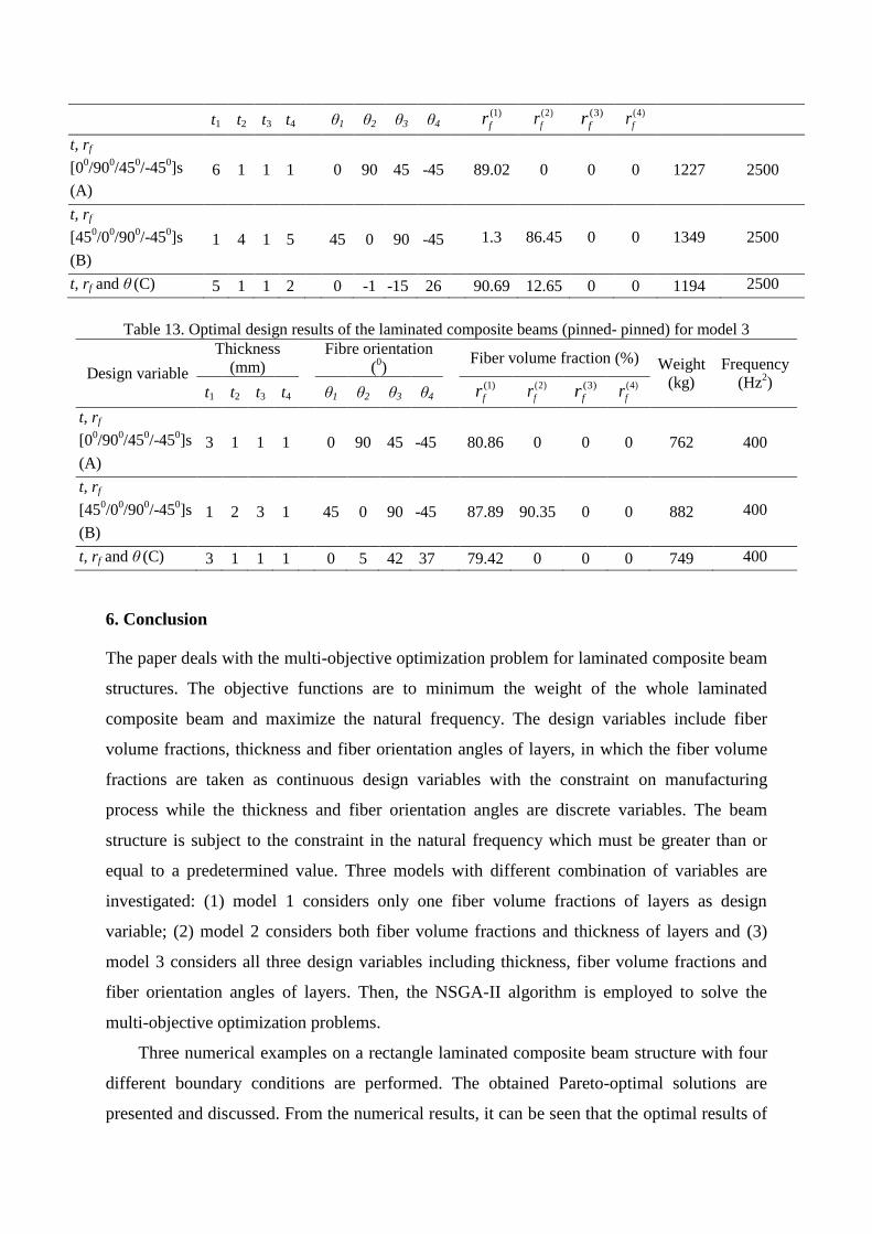
The obtained Pareto-optimal solutions of beams for various boundary conditions are
shown in Figure 11, Figure 12, Figure 13 and Figure 14. Similarly, for the purpose of
comparison, the corresponding Pareto-optimal solutions in model 2 are also shown in these
figures. It can be seen that the fiber orientation also affects the optimal design results. In all
cases of boundary conditions, the results of model 3 corresponding three design variables are
better than the solutions of model 2 with fixed fiber orientations.
Tables from Table 10 to Table 13 list the values of specific design points which have the
smallest frequency on Pareto-optimal solutions of Figures from Figure 11 to Figure 14. As
can be seen from these tables that model 3 yields different optimal solutions with those of
model 2 and it always gives the smallest weight corresponding with the same frequency
(1000 Hz). This reveals that fiber orientations angles have a useful effect on the Pareto-
optimal solutions.
Figure 11. Pareto-optimal solutions of fixed–fixed beam for model 3 and model 2.
1500 2000 2500 30001
1.5
2
2.5
3
3.5
4x 10
4
Fre
quen
cy
Weight
= [0/90/45/-45] and variables: rf , t
= [45/0/90/-45] and variables: rf , t
Variables: rf , t ,
C (1636; 10000)
B (1778; 10000)
A (1645; 10000)
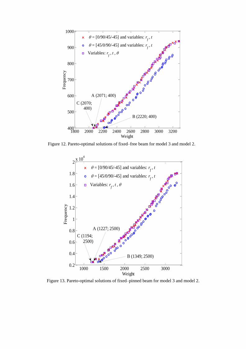
Figure 12. Pareto-optimal solutions of fixed–free beam for model 3 and model 2.
Figure 13. Pareto-optimal solutions of fixed–pinned beam for model 3 and model 2.
1800 2000 2200 2400 2600 2800 3000 3200400
500
600
700
800
900
1000
Fre
qu
en
cy
Weight
= [0/90/45/-45] and variables: rf , t
= [45/0/90/-45] and variables: rf , t
Variables: rf , t ,
C (2070; 400)
A (2071; 400)
B (2220; 400)
1000 1500 2000 2500 30000.2
0.4
0.6
0.8
1
1.2
1.4
1.6
1.8
2x 10
4
Fre
qu
en
cy
Weight
= [0/90/45/-45] and variables: rf , t
= [45/0/90/-45] and variables: rf , t
Variables: rf , t ,
A (1227; 2500)
C (1194; 2500)
B (1349; 2500)

Figure 14. Pareto-optimal solutions of pinned- pinned beam for model 3 and model 2.
Table 10. Optimal design results of the laminated composite beams (fixed–fixed) for model 3
Design variable
Thickness
(mm)
Fibre orientation
(0)
Fiber volume fraction
(%) Weight
(kg)
Frequency
(Hz2)
t1 t2 t3 t4 θ1 θ2 θ3 θ4 (1)
fr (2)
fr (3)
fr (4)
fr
t, rf
[00/90
0/45
0/-45
0]s
(A)
6 5 1 1 0 90 45 -45 85.39 0 0 0 1645 10000
t, rf
[450/0
0/90
0/-45
0]s
(B)
1 6 3 4 45 0 90 -45 18.65 90.69 0 0 1778 10000
t, rf and θ (C) 5 2 2 4 0 -2 -60 -44 90.69 19.75 0 0 1636 10000
Table 11. Optimal design results of the laminated composite beams (fixed–free) for model 3
Design variable
Thickness
(mm)
Fibre orientation
(0)
Fiber volume fraction (%) Weight
(kg)
Frequency
(Hz2)
t1 t2 t3 t4 θ1 θ2 θ3 θ4 (1)
fr (2)
fr (3)
fr (4)
fr
t, rf
[00/90
0/45
0/-45
0]s
(A)
8 1 6 1 0 90 45 -45 90.69 0 0 0 2071 400
t, rf
[450/0
0/90
0/-45
0]s
(B)
1 8 7 1 45 0 90 -45 84.85 90.69 0 0 2220 400
t, rf and θ (C) 8 1 1 6 0 32 -6 -35 90.51 0 0 0 2070 400
Table 12. Optimal design results of the laminated composite beams (fixed–pinned) for model 3
Design variable Thickness
(mm)
Fibre orientation
(0)
Fiber volume fraction (%) Weight
(kg)
Frequency
(Hz2)
0 500 1000 1500 2000 2500 3000 35000
1000
2000
3000
4000
5000
6000
7000
8000
Fre
qu
en
cy
Weight
= [0/90/45/-45] and variables: rf , t
= [45/0/90/-45] and variables: rf , t
Variables: rf , t ,
A (762; 400)
B (882; 400)
C (749; 400)
t1 t2 t3 t4 θ1 θ2 θ3 θ4 (1)
fr (2)
fr (3)
fr (4)
fr
t, rf
[00/90
0/45
0/-45
0]s
(A)
6 1 1 1 0 90 45 -45 89.02 0 0 0 1227 2500
t, rf
[450/0
0/90
0/-45
0]s
(B)
1 4 1 5 45 0 90 -45 1.3 86.45 0 0 1349 2500
t, rf and θ (C) 5 1 1 2 0 -1 -15 26 90.69 12.65 0 0 1194 2500
Table 13. Optimal design results of the laminated composite beams (pinned- pinned) for model 3
Design variable
Thickness
(mm)
Fibre orientation
(0)
Fiber volume fraction (%) Weight
(kg)
Frequency
(Hz2)
t1 t2 t3 t4 θ1 θ2 θ3 θ4 (1)
fr (2)
fr (3)
fr (4)
fr
t, rf
[00/90
0/45
0/-45
0]s
(A)
3 1 1 1 0 90 45 -45 80.86 0 0 0 762 400
t, rf
[450/0
0/90
0/-45
0]s
(B)
1 2 3 1 45 0 90 -45 87.89 90.35 0 0 882 400
t, rf and θ (C) 3 1 1 1 0 5 42 37 79.42 0 0 0 749 400
6. Conclusion
The paper deals with the multi-objective optimization problem for laminated composite beam
structures. The objective functions are to minimum the weight of the whole laminated
composite beam and maximize the natural frequency. The design variables include fiber
volume fractions, thickness and fiber orientation angles of layers, in which the fiber volume
fractions are taken as continuous design variables with the constraint on manufacturing
process while the thickness and fiber orientation angles are discrete variables. The beam
structure is subject to the constraint in the natural frequency which must be greater than or
equal to a predetermined value. Three models with different combination of variables are
investigated: (1) model 1 considers only one fiber volume fractions of layers as design
variable; (2) model 2 considers both fiber volume fractions and thickness of layers and (3)
model 3 considers all three design variables including thickness, fiber volume fractions and
fiber orientation angles of layers. Then, the NSGA-II algorithm is employed to solve the
multi-objective optimization problems.
Three numerical examples on a rectangle laminated composite beam structure with four
different boundary conditions are performed. The obtained Pareto-optimal solutions are
presented and discussed. From the numerical results, it can be seen that the optimal results of

model 2 and model 3 outperform those of model 1. This is because of the presence of the
design variable "thickness of the layers" in the models 2 and 3. In addition, the numerical
results also show the useful effect of the third design variable "fiber orientation angles of
layers" in the model 3 compared to the model 2. The results show that model 3 yields
improved optimal solutions compared to those of model 2.
Acknowledgements
This research is funded by Vietnam National Foundation for Science and Technology
Development (NAFOSTED) under grant number 107.99-2014.11.
References
[1] Ghashochi Bargh H, Sadr MH. Stacking sequence optimization of composite plates for
maximum fundamental frequency using particle swarm optimization algorithm.
Meccanica 2012;47:719–30. doi:10.1007/s11012-011-9482-5.
[2] Narita Y. Layerwise optimization for the maximum fundamental frequency of
laminated composite plates. J Sound Vib 2003;263:1005–16.
doi:http://dx.doi.org/10.1016/S0022-460X(03)00270-0.
[3] Apalak ZG, Apalak MK, Ekici R, Yildirim M. Layer optimization for maximum
fundamental frequency of rigid point-supported laminated composite plates. Polym
Compos 2011;32:1988–2000. doi:10.1002/pc.21230.
[4] Apalak MK, Karaboga D, Akay B. The Artificial Bee Colony algorithm in layer
optimization for the maximum fundamental frequency of symmetrical laminated
composite plates. Eng Optim 2014;46:420–37. doi:10.1080/0305215X.2013.776551.
[5] Sadr MH, Ghashochi Bargh H. Optimization of laminated composite plates for
maximum fundamental frequency using Elitist-Genetic algorithm and finite strip
method. J Glob Optim 2012;54:707–28. doi:10.1007/s10898-011-9787-x.
[6] Topal U. Frequency optimization of laminated composite plates with different
intermediate line supports. Sci Eng Compos Mater 2012;19:295. doi:10.1515/secm-
2012-0004.
[7] Hwang S-F, Hsu Y-C, Chen Y. A genetic algorithm for the optimization of fiber
angles in composite laminates. J Mech Sci Technol 2014;28:3163–9.
doi:10.1007/s12206-014-0725-y.
[8] Aymerich F, Serra M. Optimization of laminate stacking sequence for maximum
buckling load using the ant colony optimization (ACO) metaheuristic. Compos Part A
Appl Sci Manuf 2008;39:262–72. doi:10.1016/j.compositesa.2007.10.011.
[9] Jing Z, Fan X, Sun Q. Stacking sequence optimization of composite laminates for
maximum buckling load using permutation search algorithm. Compos Struct
2015;121:225–36. doi:http://dx.doi.org/10.1016/j.compstruct.2014.10.031.
[10] Ho-Huu V, Do-Thi TD, Dang-Trung H, Vo-Duy T, Nguyen-Thoi T. Optimization of
laminated composite plates for maximizing buckling load using improved differential
evolution and smoothed finite element method. Compos Struct 2016;146:132–47.
doi:10.1016/j.compstruct.2016.03.016.
[11] Hajmohammad MH, Salari M, Hashemi S a., Esfe MH. Optimization of stacking
sequence of composite laminates for optimizing buckling load by neural network and
genetic algorithm. Indian J Sci Technol 2013;6:5070–7.

doi:10.17485/IJST/2013/V6I8/36346.
[12] Adali S, Richter A, Verijenko VE, Summers EB. Optimal design of hybrid laminates with discrete ply angles for maximum buckling load and minimum cost. Compos Struct 1995;32:409–15. doi:10.1016/0263-8223(95)00067-4.
[13] Narita Y, Turvey GJ. Maximizing the buckling loads of symmetrically laminated composite rectangular plates using a layerwise optimization approach. Proc Inst Mech Eng Part C J Mech Eng Sci 2004;218:681–91. doi:10.1243/0954406041319554.
[14] Le-Anh L, Nguyen-Thoi T, Ho-Huu V, Dang-Trung H, Bui-Xuan T. Static and frequency optimization of folded laminated composite plates using an adjusted Differential Evolution algorithm and a smoothed triangular plate element. Compos Struct 2015;127:382–94. doi:10.1016/j.compstruct.2015.02.069.
[15] Ghasemi H, Kerfriden P, Bordas SPA, Muthu J, Zi G, Rabczuk T. Interfacial shear stress optimization in sandwich beams with polymeric core using non-uniform distribution of reinforcing ingredients. Compos Struct 2015;120:221–30.
doi:http://dx.doi.org/10.1016/j.compstruct.2014.10.005.
[16] Ghasemi H, Brighenti R, Zhuang X, Muthu J, Rabczuk T. Optimal fiber content and distribution in fiber-reinforced solids using a reliability and NURBS based sequential optimization approach. Struct Multidiscip Optim 2015;51:99–112.
doi:10.1007/s00158-014-1114-y.
[17] Ghasemi H, Brighenti R, Zhuang X, Muthu J, Rabczuk T. Optimization of fiber distribution in fiber reinforced composite by using NURBS functions. Comput Mater Sci 2014;83:463–73. doi:http://dx.doi.org/10.1016/j.commatsci.2013.11.032.
[18] Cho H-K. Design optimization of laminated composite plates with static and dynamic considerations in hygrothermal environments. Int J Precis Eng Manuf 2013;14:1387–
94. doi:10.1007/s12541-013-0187-7.
[19] Liu Q. Exact sensitivity analysis of stresses and lightweight design of Timoshenko composite beams. Compos Struct 2016;143:272–86.
doi:http://dx.doi.org/10.1016/j.compstruct.2016.02.028.
[20] Fan H-T, Wang H, Chen X-H. An optimization method for composite structures with ply-drops. Compos Struct 2016;136:650–61.
doi:http://dx.doi.org/10.1016/j.compstruct.2015.11.003.
[21] Ghasemi H, Park HS, Rabczuk T. A level-set based IGA formulation for topology optimization of flexoelectric materials. Comput Methods Appl Mech Eng
2017;313:239–58. doi:http://dx.doi.org/10.1016/j.cma.2016.09.029.
[22] Nanthakumar SS, Valizadeh N, Park HS, Rabczuk T. Surface effects on shape and topology optimization of nanostructures. Comput Mech 2015;56:97–112.
doi:10.1007/s00466-015-1159-9.
[23] Liu Q. Analytical sensitivity analysis of eigenvalues and lightweight design of composite laminated beams. Compos Struct 2015;134:918–26.
doi:10.1016/j.compstruct.2015.09.002.
[24] Liu Q, Paavola J. Lightweight design of composite laminated structures with frequency constraint. Compos Struct 2015. doi:10.1016/j.compstruct.2015.08.116.
[25] Vo-Duy T, Ho-Huu V, Do-Thi TD, Dang-Trung H, Nguyen-Thoi T. A global numerical approach for lightweight design optimization of laminated composite plates subjected to frequency constraints. Compos Struct 2017;159:646–55.
doi:10.1016/j.compstruct.2016.09.059.
[26] Pelletier JL, Vel SS. Multi-objective optimization of fiber reinforced composite laminates for strength, stiffness and minimal mass. Comput Struct 2006;84:2065–80. doi:http://dx.doi.org/10.1016/j.compstruc.2006.06.001.
[27] Lee DS, Morillo C, Bugeda G, Oller S, Onate E. Multilayered composite structure

design optimisation using distributed/parallel multi-objective evolutionary algorithms.
Compos Struct 2012;94:1087–96.
doi:http://dx.doi.org/10.1016/j.compstruct.2011.10.009.
[28] Vosoughi AR, Nikoo MR. Maximum fundamental frequency and thermal buckling temperature of laminated composite plates by a new hybrid multi-objective optimization technique. Thin-Walled Struct 2015;95:408–15.
doi:http://dx.doi.org/10.1016/j.tws.2015.07.014.
[29] Honda S, Igarashi T, Narita Y. Multi-objective optimization of curvilinear fiber shapes for laminated composite plates by using NSGA-II. Compos Part B Eng 2013;45:1071–
8. doi:http://dx.doi.org/10.1016/j.compositesb.2012.07.056.
[30] Deb K, Pratap A, Agarwal S, Meyarivan T. A fast and elitist multiobjective genetic algorithm: NSGA-II. IEEE Trans Evol Comput 2002;6:182–97.
doi:10.1109/4235.996017.
[31] Robert M. Jones. Mechanics Of Composite Materials. 2 edition. CRC Press; 1998.
[32] Altenbach H, Altenbach J, Kissing W. Mechanics of Composite Structural Elements. 1st ed. Berlin, Heidelberg: Springer Berlin Heidelberg; 2004.
doi:10.1007/978-3-662-08589-9.
[33] Marler RT, Arora JS. Survey of multi-objective optimization methods for engineering. Struct Multidiscip Optim 2004;26:369–95. doi:10.1007/s00158-003-0368-6.
[34] Zitzler E, Laumanns M, Thiele L. SPEA2: Improving the strength Pareto evolutionary algorithm. Eurogen, vol. 3242, 2001, p. 95–100.
[35] Zhang Q, Li H. MOEA/D: A Multiobjective Evolutionary Algorithm Based on Decomposition. IEEE Trans Evol Comput 2007;11:712–31.
doi:10.1109/TEVC.2007.892759.
[36] Srinivas N, Deb K. Muiltiobjective Optimization Using Nondominated Sorting in Genetic Algorithms. Evol Comput 1994;2:221–48. doi:10.1162/evco.1994.2.3.221.
[37] Liu GR, Chen SC. Flaw detection in sandwich plates based on time-harmonic response using genetic algorithm. Comput Methods Appl Mech Eng 2001;190:5505–14.
doi:http://dx.doi.org/10.1016/S0045-7825(01)00173-6.
[38] Zheng H, Cai C, Pau GSH, Liu GR. Minimizing vibration response of cylindrical shells through layout optimization of passive constrained layer damping treatments. J Sound Vib 2005;279:739–56. doi:http://dx.doi.org/10.1016/j.jsv.2003.11.020.
[39] Liu GR, Ma HJ, Wang YC. Material characterization of composite laminates using dynamic response and real parameter-coded microgenetic algorithm. Eng Comput 2005;20:295–308. doi:10.1007/s00366-004-0298-y.
[40] Xu YG, Liu GR, Wu ZP. Damage Detection for Composite Plates Using Lamb Waves and Projection Genetic Algorithm. AIAA J 2002;40:1860–6. doi:10.2514/2.1865.
[41] Goldberg DE. Genetic Algorithms in Search, Optimization, and Machine Learning. Reading, MA: Addison-Wesley; 1989.
[42] Dhanalakshmi S, Kannan S, Mahadevan K, Baskar S. Application of modified NSGA-
II algorithm to Combined Economic and Emission Dispatch problem. Int J Electr Power Energy Syst 2011;33:992–1002.
doi:http://dx.doi.org/10.1016/j.ijepes.2011.01.014.
[43] Kannan S, Baskar S, McCalley JD, Murugan P. Application of NSGA-II Algorithm to Generation Expansion Planning. IEEE Trans Power Syst 2009;24:454–61.
doi:10.1109/TPWRS.2008.2004737.
[44] Martínez-Vargas A, Domínguez-Guerrero J, Andrade ÁG, Sepúlveda R, Montiel-Ross
O. Application of NSGA-II algorithm to the spectrum assignment problem in spectrum sharing networks. Appl Soft Comput 2016;39:188–98.
doi:http://dx.doi.org/10.1016/j.asoc.2015.11.010.

[45] Soyel H, Tekguc U, Demirel H. Application of NSGA-II to feature selection for facial
expression recognition. Comput Electr Eng 2011;37:1232–40.
doi:http://dx.doi.org/10.1016/j.compeleceng.2011.01.010.
[46] Yu X, Liong S-Y, Atiquzzaman M. Alternative Decision Making in Water Distribution
Network with NSGA-II 2006. doi:10.1061/(ASCE)0733-9496(2006)132:2(122).